design of box girders
DESCRIPTION
CIVILTRANSCRIPT

Engineering Structures 40 (2012) 299–316
Contents lists available at SciVerse ScienceDirect
Engineering Structures
journal homepage: www.elsevier .com/ locate /engstruct
Identification of local stress parameters influencing the optimum designof box girders
Mirko Djelosevic a,⇑, Vladeta Gajic b, Dragan Petrovic a, Milan Bizic a
a Faculty of Mechanical Engineering Kraljevo, University of Kragujevac, Dositejeva 19, 36000 Kraljevo, Serbiab Faculty of Technical Sciences Novi Sad, University of Novi Sad, Dositeja Obradovica 6, 21000 Novi Sad, Serbia
a r t i c l e i n f o a b s t r a c t
Article history:Received 15 July 2011Revised 29 December 2011Accepted 5 February 2012Available online 30 March 2012
Keywords:Influential zoneGirder segmentLocal stressDeformationOptimum design
0141-0296/$ - see front matter � 2012 Elsevier Ltd. Ahttp://dx.doi.org/10.1016/j.engstruct.2012.02.040
⇑ Corresponding author. Tel.: +381 36 383 269; faxE-mail addresses: [email protected]
(V. Gajic), [email protected] (D. Petrovic), bizicURL: http://www.mfkv.kg.ac.rs (M. Djelosevic).
Research into the effect of local stress on the carrying capacity and optimum design of box girders wasperformed in this paper. A mathematical model of the girder was created for the purpose of definingthe stress–strain state of local character. Mathematical dependence which defines the length of the influ-ential zone in box girders was established. The segment length relevant for the analysis of local stress isfunctionally dependent on geometrical parameters of the girder cross section, area of action and size ofload. The methodology carried out in this paper showed that the identification of local stress can be per-formed only on a segment of the girder. The procedure of calculation and experimental determination ofthe local stress state in carrying structures was thus considerably simplified, without reducing accuracy.The influential parameters were identified and the guidelines for optimum design of quadrilateral shapeof the girder cross section were given from the aspect of local stress. The comparative analysis was usedto establish, under the same conditions of global carrying capacity, a more favourable stress state in trap-ezoidal shape in comparison with the traditional rectangular cross section of the girder. Application of theresults of this paper is a contribution to the process of optimal design of supporting structures, especiallythose that are used for construction of transport equipment and rack structures in storage systems, wherethe effect of reducing the weight affects on the efficiency of transport in supply chains.
� 2012 Elsevier Ltd. All rights reserved.
1. Introduction
Modern development of structural elements of carryingstructures based on the application of sophisticated techniqueand experimental testing, with adequate support of manufacturingtechnology, emphasizes the importance of box girders. The keyactivity in design of structures, either box or lattice girders, is theoptimization of shape of the cross section. Therefore, it is necessaryto mathematically formulate the problem of optimization so thatinfluential geometrical parameters of the cross section couldprovide the minimum mass function.
Paper [1] considered the general approach to the cross sectionoptimization for equilateral polygons, from triangular to circularones. The optimization of box sections was extended to nonequi-lateral profiles in papers [2,3], where the pentagonal shape appliedin the telescopic boom of the autocrane was considered. In thesame paper, the researchers state that polygonal shapes providemore rational use of inserted material and that they are particu-larly important for reducing the effect of local stress.
ll rights reserved.
: +381 36 383 377.(M. Djelosevic), [email protected]@mfkv.kg.ac.rs (M. Bizic).
The research in papers [4,5] performed the optimization ofdimensions and shapes of the cross section of lattice structures,where the subject of analysis covered triangular, rectangular andtrapezoidal shapes.
Papers [6,7] treat the optimization of shapes of the cross sectionof the rotating structural element subjected to load along the lon-gitudinal axis, where inertial forces are also taken into account.
The previously cited papers show that the methodology of crosssection optimization depends on the type of structure as well as onits functional characteristics.
Papers [1–5] focus on the cross section analysis based on globalcarrying capacity, i.e. the mass function which is the subject ofanalysis contains only stress components due to global stress,while the phenomenon of local stress is marginalized. From the as-pect of global carrying capacity, the optimization result gives sucha shape of cross section that provides maximum carrying capacityfor a certain type of stress with the minimum mass of the struc-tural element. The optimization procedure based on the principleof global carrying capacity was adequately performed only in caseswhen local stress had a negligible influence in relation to the over-all stress state. Such a case is dominant in carrying structures oflattice type, which was analyzed in [4,5]. The lattice girder ele-ments are exclusively linear elements, and the potential points oflocal stress occurrence are zones of mutual connection of elements,

300 M. Djelosevic et al. / Engineering Structures 40 (2012) 299–316
which can be avoided by a suitable design solution [8]. The struc-tures made of box girders and designed according to the criterionof global carrying capacity are subjected to local stress in experi-mental testing or in the exploitation process. It results in consider-ably larger deformations, i.e. stresses higher than the design ones.Under such conditions, the stress state is is characterized by a sig-nificant rise in stress in the zone of direct load [2,3], which fre-quently leads to damage and even to the destruction of thematerial. It indicates the additional stress component. That iswhy local stress analysis is important.
The focal point of research in this paper is definition of thelength of the zone of influence due to local stress so that localstress–strain state analysis could be carried out on the relevantsegment of the box girder. The segment length corresponds tothe length of the influential zone of local stress, and the cross sec-tion is identical to the shape of the box girder considered. This is ofexclusively practical importance for experimental analysis in labo-ratory conditions where, in order to measure local stresses, it is en-ough to have a girder segment whose length is considerablysmaller than the length of the box girder. Mathematical interpreta-tion of deformation and stress values from the aspect of local stressgives guidelines for the optimum design of box girders.
Fig. 1. Model for global deformation analysis.
2. Research into thin-walled welded girders
Numerous studies of girders made of plate elements haverecently been carried out and they have mostly been based onexperimental testing and the FEM analysis. Generally, all researchcan be divided into two basic groups:
1. Research into steel girders in the domain of plasticity.2. Research into steel girders in the elastic range behavior.
The phenomenon of plasticity and resistance of girders to buck-ling is systematically described in [9,10], where the problems ofelastic stability and critical load are treated. Researchers [11–14]consider the problem of boundary carrying capacity of the thin-walled welded I-girder for the case of centric and eccentric actionof moving load. The correlation between those two cases of load isestablished, and experimental data are used for improving themathematical model which describes the mechanism of plasticbehavior of the material. The influence of longitudinal stiffeningin complex girders of open type is considered in [15], where atheoretical model for determination of boundary moving load isproposed. Research [16,17] analyzes the boundary durability ofthe longitudinally stiffened I-girder, where favourable shapes ofstiffeners are considered. Nonlinear finite elements are applied in[17–19] for the analysis of material behavior in the zone of plastic-ity, where the obtained results are compared with the theoreticalones. In addition, FEM is very important for defining measuringpoints before carrying out experiments. A wide application ofbox girders and open girders, especially in construction of bridgestructures, is the subject of analysis in [20], where the insertionof web [21] has a significant effect on the carrying capacity andoptimization of the girder.
The application of box girders, i.e. closed thin-walled weldedstructures is accompanied by the problem of stability loss, whichdraws special attention. The phenomenon of local instability, i.e.buckling on a separated element or plate was analyzed in [22],by the numerical procedure and FEM, where the obtained resultsare in accordance with the existing models of stress distribution.In [23], the problem of box telescopic boom of the autocrane wasanalyzed with the application of ANSYS, where modes of bucklingwere presented. These examples show a great influence of localstress due to an interactive contact of boom segments. The analysis
of elastic buckling of girder plates is linear and it is important fordefinition of maximum loads that will not cause plastic deforma-tions and thus reduce or completely endanger the functionalityof the structure [24–28].
The application of composite materials [29,30] is of great signif-icance. Hollow box girders are subject to local buckling of plates.The use of filling (e.g. concrete) prevents displacements towardthe interior, while buckling toward the outside is enabled. Theapplication of composites allows the action of a greater criticalforce that can be borne by the girder without a failure.
The idea of the paper is to numerically establish the behavior ofthe girder – with the box girder as an example – by means of amathematical model and to check its validity by FEM, showingthe influence of geometrical values and loads on the carryingcapacity in the domain of elasticity.
3. Analysis of the problem
The subject of research in this paper covers:
1. Analysis of deflection of global stress and the stress–strain stateof the girder from the aspect of local stress.
2. Identification of the influential zone due to local stress.3. Determination of stress and strain values on a girder segment.4. Definition of the local stress state parameters which influence
the optimum design of the girder cross section shape.
In order to realize the mentioned research, it is necessary to car-ry out certain analyses of model adequacy from the aspect ofdetermination of displacement and stress state of the girder.Classification into models of local and global carrying capacitywas performed for the purpose of a simpler analysis of the valuesinfluencing the carrying capacity of the girder. In that sense, thegirder in (Figs. 1–3) will be considered. The physical model of thegirder from the aspect of global carrying capacity (Fig. 1) repre-sents a line girder. The deflection and the normal stress of thegirder are defined through the following familiar expressions:
f ðzÞ ¼ ql4
24EIzl
� �2
ul
� �� lþ u
2l
� �4
þ l� u2l
� �4" #
� 2ul
� � zl
� �3( )
ð1Þ
fmax �Ql3
48EI¼ ðquvÞl3
48EI; for u� l ð2Þ

Fig. 2. Model for local deformation analysis.
Fig. 3. Box girder under uniform continuous load.
Fig. 4. Box girder plate directly subjected to the action of uniform continuous load.
M. Djelosevic et al. / Engineering Structures 40 (2012) 299–316 301
rx ¼MI� ymax ð3Þ
The physical model of the girder from the aspect of local carryingcapacity (Fig. 2) is based on the principle of separation of cross sec-tion elements (plates). The essential difference between these twomodels that the line girder model does not take into account defor-mation of the plates which constitute the girder. This explains theexistence of an additional stress component, which makes anabrupt jump in the zone of load action [2,3], which is characteristicof plate elements. Under the action of external load there is aninteraction between global and local stresses [31]. It creates a com-plex stress–strain picture of the girder, which is unfavourable forthe analysis of influential parameters of carrying capacity. By pre-venting global displacement of the girder, it is possible to separatetheir mutual influence and perform an independent analysis of localbehavior. It can be illustrated by considering a part of the flangeplate around the zone of load action (Fig. 4). Under the action ofglobal stress, the plate moves vertically by the value of globaldeflection. It is equivalent to the existence of elastic supports withthe rigidity kg along the edges of the plate. Mathematical identifica-tion of the plate establishes that the values and distribution ofstress do not have significant deviations compared to the freely sup-ported plate with rigid supports. It confirms the fact that plate dis-placement due to global load does not have any influence on thelocal stress state, and the resulting deflection of the plate is equalto the sum of local and global deflections.
4. Mathematical model of local stress
The mathematical model for definition of the local stress–strainstate is based on the following assumptions:
1. Each plate of the girder is considered a freely supported plate2. Displacements due to elastic deformations of the plate supports
in relation to the plate deflection due to external load areneglected
3. The influence of transverse forces in relation to the action ofexternal load and internal reactive moments on plate deforma-tion is neglected
4. The influence of action of forces in the plane of the plate in rela-tion to the other loads which cause normal stresses is eliminated.
According to these assumptions, a physical model suitable formathematical description of the stress–strain state of local charac-ter is developed (Fig. 5). From the aspect of adequacy of the math-ematical model, justification of the introduced assumptions isbased on the following analysis:
The vertical plates (webs) of the girder represent elastic sup-ports for the flange plates. In most design solutions (which is thecase in this example), these girder elements have sufficient rigiditywhich does not contribute to significant changes in the stress stateof the flange plates. A similar analysis is carried out on the verticalplates of the girder, where the influences of flange plates in thetransverse direction are manifested as supports. Thus, the girderelements (plates) can be modelled as plates that are freely sup-ported on rigid supports, which justifies the first two assumptions.The third assumption is based on the fact that transverse forcescause shear stresses whose size is small in relation to normal stres-ses. The fourth assumption is that the values of normal stresses dueto the action of planar forces are, in transversely loaded girders,negligible in relation to the identical stresses due to external loadand reactive elastic bending moment.
The deflection of plate ‘‘2’’ (Fig. 4) due to the uniform continu-ous load q(x,y), according to [32], is:
w2ðqÞ¼16 �q0
p6D2�P1
m¼1
P1n¼1
sinmpna �sinnpg
b2�sinmpu
2a �sinnpv2b2
mn � m2
a2 þ n2
b22
� �2 �sinmpx
a�sin
npyb2
ð4Þ
The inclination of plate ‘‘2’’ due to the load q(x,y) is given by theexpression:
@w2ðqÞ@y2
� �¼ 16 � q0
p5D22b�P1
m¼1
P1n¼1
sin mpna � sin npg
b2� sin mpu
2a � sin npv2b2
m � m2
a2 þ n2
b22
� �2
� sinmpx
a� cos
npyb2
ð5Þ
The deflection of freely supported plate ‘‘i’’ due to the action of mo-ments ‘‘Mi’’ and ‘‘Mi+1’’, according to [32], is:

Fig. 5. Physical model of the box girder (uniform continuous load).
302 M. Djelosevic et al. / Engineering Structures 40 (2012) 299–316
wiðMi;Miþ1Þ ¼a2
i
4p2Di�P1
m¼1
sin mpxai
m2
�Ki;mþKðiþ1Þ;m
cosh ai;m� ai;mtghai;m cosh mpy
ai� mpy
aisinh mpy
ai
� �þ
þ Kðiþ1Þ;m�Ki;m
sinh ai;m� ai;mctghai;m sinh mpy
ai� mpy
aicosh mpy
ai
� �264
375
ð6Þ
The corresponding inclinations of plate ‘‘i’’ are determined from theexpressions:
@wiðMi;Miþ1Þ@yi
� �y2¼�
b22
¼ ai
4pDi�P1
m¼1
sin mpxai
m
�ðKi;m þ Kðiþ1Þ;mÞ
ai;m
cosh2ai;mþ tghai;m
� �þ
þðKi;m � Kðiþ1Þ;mÞ ctghai;m �ai;m
sinh2ai;m
� �26664
37775
ð7Þ
@wiðMi;Miþ1Þ@yi
� �y2¼�
b22
¼ � ai
4pDi�P1
m¼1
sin mpxai
m
�ðKi;m þ Kðiþ1Þ;mÞ
ai;m
cosh2ai;mþ tghai;m
� �þ
þðKðiþ1Þ;m � Ki;mÞ ctghai;m � ai;m
sinh2ai;m
� �26664
37775
ð8Þ
The moments Mi and Mi+1 are determined according to the follow-ing series:
Mi ¼P1
m¼1Ki;m � sin
mpxa
; Miþ1 ¼P1
m¼1Kðiþ1Þ;m � sin
mpxa
ð9Þ
Ki,m and K(i+1),m are unknown coefficients as a function of ‘‘m’’.Unknown coefficients Ki,m (i = 1,2,3,4) are determined from sys-
tem of Eqs. (14)–(17).To ensure continuity of girder in lateral direction the following
conditions must be fulfilled:
Support No. 1:
@w4ðM4;M1Þ@y4
� �y4¼
b42
¼ @w1ðM1;M2Þ@y1
� �y1¼�
b12
ð10Þ
Support No. 2:
@w2ðqÞ@y2
� �y2¼�
b22
þ @w2ðM2;M3Þ@y2
� �y2¼�
b22
¼ @w1ðM1;M2Þ@y2
� �y1¼
b12
ð11ÞSupport No. 3:
@w2ðqÞ@y2
� �y2¼
b22
þ @w2ðM2;M3Þ@y2
� �y2¼
b22
¼ @w3ðM3;M4Þ@y3
� �y3¼�
b32
ð12Þ
Support No. 4:
@w3ðM3;M4Þ@y3
� �y3¼
b32
¼ @w4ðM4;M1Þ@y4
� �y4¼�
b42
ð13Þ
Eqs. (10)–(13) are equivalent with (14)–(17).
Km;1 �1
D1ðBm;1þCm;1Þþ
1D4ðBm;2þCm;2Þ
� �þKm;2 �
1D1ðBm;1�Cm;1Þ
� �
þKm;3 �0þKm;4 �1
D4ðBm;4�Cm;4Þ
� �¼0 ð14Þ
Km;1 �1
D1ðBm;1�Cm;1Þ
� �þKm;2 �
1D1ðBm;1þCm;1Þþ
1D2ðBm;2þCm;2Þ
� �
þKm;3 �1
D2ðBm;2�Cm;2Þ
� �þKm;4 �0¼
4paP1
m¼1
msinmpx
a
@w2
@y
� �����y2¼0
ð15Þ
Km;1 �0þKm;2 �1
D2ðBm;2�Cm;2Þ
� �þKm;3 �
1D2ðBm;2þCm;2Þþ
1D3ðBm;3þCm;3Þ
� �
þKm;4 �1
D3ðBm;3þCm;3Þ
� �¼�4p
aP1
m¼1
msinmpx
a
@w2
@y
� �����y2¼b2
ð16Þ

M. Djelosevic et al. / Engineering Structures 40 (2012) 299–316 303
Km;1 �1
D4ðBm;4 � Cm;4Þ
� �þ Km;2 � 0þ Km;3 �
1D3ðBm;3 � Cm;3Þ
� �
þ Km;4 �1
D3ðBm;3 þ Cm;3Þ þ
1D4ðBm;4 þ Cm;4Þ
� �¼ 0 ð17Þ
The coefficients Bi,m and Ci,m are given through the followingexpressions:
Fig. 7. Diagram of the compara
Fig. 6. Diagram of the resultin
Bi;m ¼ �ai;m
cosh2ai;m
þ tghai;m
!ð18Þ
Ci;m ¼ai;m
sinh2ai;m
� ctghai;m
!ð19Þ
tive stress ru of the girder.
g deflection of the girder.

304 M. Djelosevic et al. / Engineering Structures 40 (2012) 299–316
The coefficient ai,m has the form:
ai;m ¼mpbi
2a
� �ð20Þ
Fig. 8. Diagram of the local
Fig. 9. Diagram of the local compa
5. Analysis of global and local stresses by means of FEM
The finite element method (FEM) is used for verification of theresults obtained by the analytical procedure in Chapter 4. A proce-dure of separation between global and local stresses by means ofFEM will be presented here by applying ANSYS 12 software
deflection of the girder.
rative stress rl,u of the girder.

M. Djelosevic et al. / Engineering Structures 40 (2012) 299–316 305
package. For that purpose, the resulting deflection of the girder willfirstly be considered (Fig. 6). Elimination of global deformation ofthe girder results in local deflection of the girder (Fig. 8). Distribu-tion of global deflection which is analytically determined through(1), results from establishing the difference between total and localdeflections for the top flange plate of the girder subjected to directload. Triangular finite elements of the shell with the size of 10 mmare applied for generation of the FEM model. Girder dimensions,size of loads and conditions of support at the ends are identicalas in the physical model of the analytical method. It is interestingthat the maximum Von-Mises stresses are identical on real girder(Fig. 7) and also on girder where the global movement is prevented(Fig. 9). This leads to the conclusion that in the considered case aglobal strain has a negligible influence in compared to the localstress state.
Fig. 12. Function of deflection distribution in plate ‘‘3’’ of the girder (transversedirection).
5.1. Comparative analysis of deflections of the girder plates
Using the results obtained by the analytical procedure and FEM,a comparative analysis of deflections of the girder plates for twomutually perpendicular directions is carried out. The aim of thecomparative analysis is to confirm the correspondence betweenthe values and distribution of functions of deflections obtainedtheoretically and by means of FEM (see Figs. 10–17).
The analysis of functions of deflection distribution for the struc-tural elements (plates) of the girder established that local stress
Fig. 10. Function of deflection distribution in plate ‘‘1’’ of the girder (transversedirection).
Fig. 11. Function of deflection distribution in plate ‘‘2’’ of the girder (transversedirection).
has effect only in a certain zone of load action. The diagram inFig. 18 can illustrate it. With the increase in the width of the girder(B), other parameters being the same, the plate deflection in-creases, while the zone of influence (L) is approximately constant,for larger values of B, while for lower values of the deviation ismuch more pronounced. Similarly, the same conclusion is also per-formed for other plates of girders (plates 1, 3 and 4).
Fig. 13. Function of deflection distribution in plate ‘‘4’’ of the girder (transversedirection).
Fig. 14. Function of deflection distribution in plate ‘‘1’’ of the girder (longitudinaldirection).

Fig. 16. Function of deflection distribution in plate ‘‘3’’ of the girder (longitudinaldirection).
Fig. 18. Change of the deflection (w2) depending on the width of the girder (B).Fig. 15. Function of deflection distribution in plate ‘‘2’’ of the girder (longitudinaldirection).
Table 1Input data of the program for determination of the length of the influential zone (L).
Plate 1 2 3 4
Thickness d (mm) 5.2 6.4 5.2 6.4Length a (mm) 4000 4000 4000 4000Width b (mm) 300 200 300 200Superficial load q (kN cm�2) 0 �0.300 0 0
Measures of the area of load u (mm) 0 100 0 0v (mm) 0 50 0 0
Position of the load centre n (mm) 0 2000 0 0g1 (mm) 0 100 0 0g2 (mm) 0 0 0 0
306 M. Djelosevic et al. / Engineering Structures 40 (2012) 299–316
The model of local stress is applied for definition of the length ofthe influential zone (L) and the following expression is used:
w2ðx; yÞ ¼16 � q0
p6D2�P1
m¼1
P1n¼1
sin mpna � sin npg
b2� sin mpu
2a � sin npv2b2
mn � m2
a2 þ n2
b22
� �2
� sinmpx
a� sin
npyb2þ a2
4p2D2�P1
m¼1
sin mpxa
m2
�Km;2þKm;3cosh a2;m
� a2;mtgha2;m cosh mpya �
mpya sinh mpy
a
þ
þ Km;3�Km;2sinh a2;m
� a2;mctlgha2;m sinh mpya �
mpya cos h mpy
a
24
35
ð21Þ
Fig. 17. Function of deflection distribution in plate ‘‘4’’ of the girder (longitudinaldirection).
The length of the influential zone of the local stress state is deter-mined according to (17), so that the following condition is fulfilled:
Deflection on the edge of the plate must be less than or equal to3% of the maximum deflection, i.e.
w2 x; y ¼ b2
2
� �6 0;03 �w2;max ð22Þ
The only unknown value in the inequality (18) is x, i.e. L.At base (17) and (18) is developed software for determination of
the influential zone of local stress (see Table 1).
6. Stress–strain analysis of the girder segment
Chapter 5 identifies the influential zone of local stress (L) forthe considered cross section and size of load. It is, before all, ofpractical importance in calculation of structures by means ofFEM, especially in experimental testing. Besides, a modern ap-proach to calculation of the stress state of the box girder is pre-sented. The classical procedure of stress calculation in linearstructures in the domain of global stress does not provide validresults. Deviations are particularly remarkable in box girders,but also in other thin-walled structural elements, in which thelocal stress state has a dominant effect. This chapter also showsthat the girder segment with the length L is quite sufficient forthe stress analysis of the girder for all methods of calculation(theoretical, FEM and experimental).
Calculation conditions of the FEM model with respect to load,geometry and constraints are identical to those for the theoreticalmodel. Triangular finite elements of the shell with the size of10 mm were applied for generation of the FEM model. The valuesof deflection read from the FEM model are presented in compara-tive diagrams (Figs. 26–33), and it can be stated that there is highcorrespondence of results with regard to the values and trends ofdistribution.

Fig. 19. Total deflection of the girder segment of rectangular cross section.
Fig. 20. Equivalent stress of the girder segment of rectangular cross section.
M. Djelosevic et al. / Engineering Structures 40 (2012) 299–316 307
According to Figs. 8 and 9 and Figs. 19 and 20 it can be concludedthat the distribution and the maximum values of the deflection andequivalent stress are identical, and this conclusion confirm thevalidity of determining the length of the girder segment.
7. Experimental analysis
The experimental analysis was based on the settings of the pre-vious sections. Its purpose was to verify the FEM model and
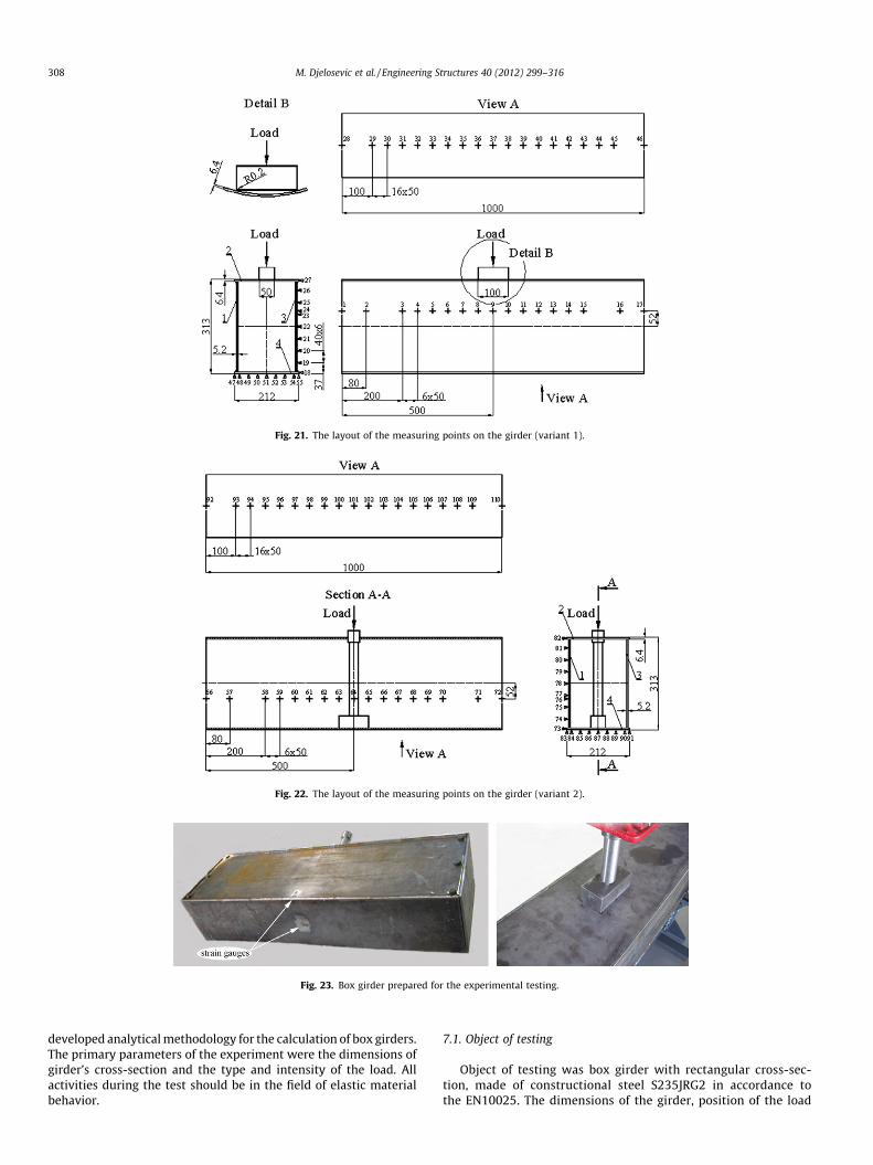
Fig. 21. The layout of the measuring points on the girder (variant 1).
Fig. 22. The layout of the measuring points on the girder (variant 2).
Fig. 23. Box girder prepared for the experimental testing.
308 M. Djelosevic et al. / Engineering Structures 40 (2012) 299–316
developed analytical methodology for the calculation of box girders.The primary parameters of the experiment were the dimensions ofgirder’s cross-section and the type and intensity of the load. Allactivities during the test should be in the field of elastic materialbehavior.
7.1. Object of testing
Object of testing was box girder with rectangular cross-sec-tion, made of constructional steel S235JRG2 in accordance tothe EN10025. The dimensions of the girder, position of the load
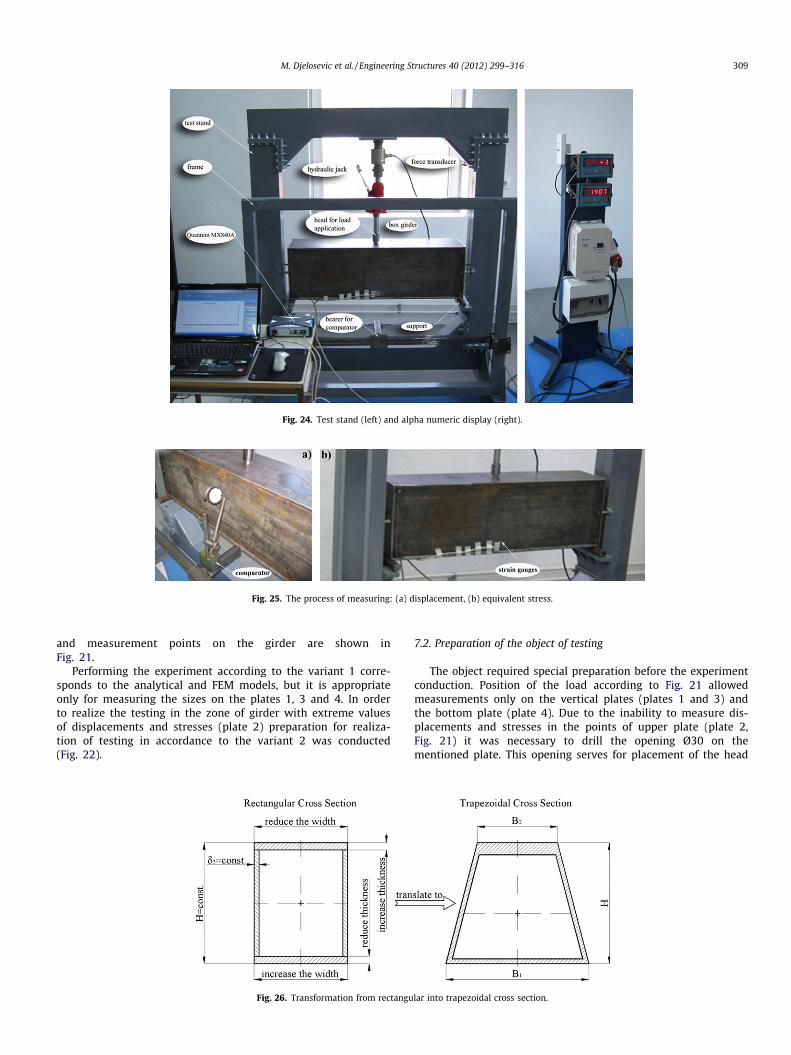
Fig. 24. Test stand (left) and alpha numeric display (right).
Fig. 25. The process of measuring: (a) displacement, (b) equivalent stress.
M. Djelosevic et al. / Engineering Structures 40 (2012) 299–316 309
and measurement points on the girder are shown inFig. 21.
Performing the experiment according to the variant 1 corre-sponds to the analytical and FEM models, but it is appropriateonly for measuring the sizes on the plates 1, 3 and 4. In orderto realize the testing in the zone of girder with extreme valuesof displacements and stresses (plate 2) preparation for realiza-tion of testing in accordance to the variant 2 was conducted(Fig. 22).
Fig. 26. Transformation from rectangu
7.2. Preparation of the object of testing
The object required special preparation before the experimentconduction. Position of the load according to Fig. 21 allowedmeasurements only on the vertical plates (plates 1 and 3) andthe bottom plate (plate 4). Due to the inability to measure dis-placements and stresses in the points of upper plate (plate 2,Fig. 21) it was necessary to drill the opening Ø30 on thementioned plate. This opening serves for placement of the head
lar into trapezoidal cross section.

Fig. 27. Total displacement of the girder segment with the trapezoidal cross section (variant 1).
310 M. Djelosevic et al. / Engineering Structures 40 (2012) 299–316
for load application (Fig. 22). In this way the roles of the plates 2and 4 were replaced, while the displacements and stresses of theplates have the same intensity and opposite sign compared tothe case from Fig. 21. The influence of the hole does not have
Fig. 28. Comparative stress of the girder with
significant effect on the measurement, which is consistent with[33] (see Fig. 23).
The sides of the girder are closed with the detachable plateswhich allows placement of the head for load application. The
the trapezoidal cross section (variant 1).

Fig. 29. Total deflection of the girder segment with the trapezoidal cross section (variant 2).
M. Djelosevic et al. / Engineering Structures 40 (2012) 299–316 311
detachable plates are pressed in the girder which allows the freelysupporting of plates on their ends.
7.3. Preparation and organization of testing
The testing is realized on the multipurpose test stand with thecarrying capacity 110 kN. The girder is placed on the roller sup-
Fig. 30. Comparative stress of the girder with
ports of the test stand, and then alignment and insurance ofunforeseen moving is performed. Thus supporting provides thecondition for freely supported girder. On the pedestal of the teststand is mounted a frame with the carrier of comparators whichpurpose is measurement of displacements of the plates. Settingof force is provided using manual hydraulic jack whose carryingcapacity is 50 kN. Registration of force is provided using the force
the trapezoidal cross section (variant 2).
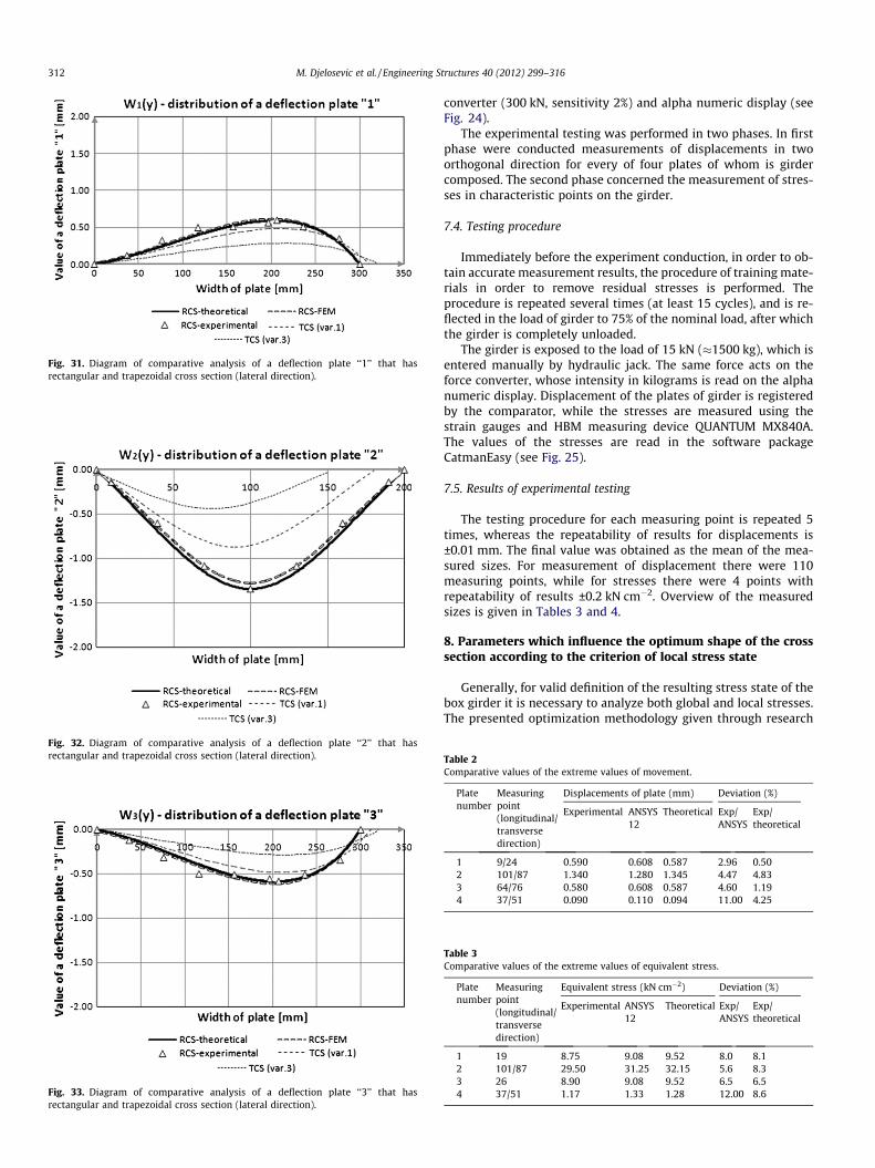
Fig. 31. Diagram of comparative analysis of a deflection plate ‘‘1’’ that hasrectangular and trapezoidal cross section (lateral direction).
Fig. 32. Diagram of comparative analysis of a deflection plate ‘‘2’’ that hasrectangular and trapezoidal cross section (lateral direction).
Fig. 33. Diagram of comparative analysis of a deflection plate ‘‘3’’ that hasrectangular and trapezoidal cross section (lateral direction).
312 M. Djelosevic et al. / Engineering Structures 40 (2012) 299–316
converter (300 kN, sensitivity 2%) and alpha numeric display (seeFig. 24).
The experimental testing was performed in two phases. In firstphase were conducted measurements of displacements in twoorthogonal direction for every of four plates of whom is girdercomposed. The second phase concerned the measurement of stres-ses in characteristic points on the girder.
7.4. Testing procedure
Immediately before the experiment conduction, in order to ob-tain accurate measurement results, the procedure of training mate-rials in order to remove residual stresses is performed. Theprocedure is repeated several times (at least 15 cycles), and is re-flected in the load of girder to 75% of the nominal load, after whichthe girder is completely unloaded.
The girder is exposed to the load of 15 kN (�1500 kg), which isentered manually by hydraulic jack. The same force acts on theforce converter, whose intensity in kilograms is read on the alphanumeric display. Displacement of the plates of girder is registeredby the comparator, while the stresses are measured using thestrain gauges and HBM measuring device QUANTUM MX840A.The values of the stresses are read in the software packageCatmanEasy (see Fig. 25).
7.5. Results of experimental testing
The testing procedure for each measuring point is repeated 5times, whereas the repeatability of results for displacements is±0.01 mm. The final value was obtained as the mean of the mea-sured sizes. For measurement of displacement there were 110measuring points, while for stresses there were 4 points withrepeatability of results ±0.2 kN cm�2. Overview of the measuredsizes is given in Tables 3 and 4.
8. Parameters which influence the optimum shape of the crosssection according to the criterion of local stress state
Generally, for valid definition of the resulting stress state of thebox girder it is necessary to analyze both global and local stresses.The presented optimization methodology given through research
Table 3Comparative values of the extreme values of equivalent stress.
Platenumber
Measuringpoint(longitudinal/transversedirection)
Equivalent stress (kN cm�2) Deviation (%)
Experimental ANSYS12
Theoretical Exp/ANSYS
Exp/theoretical
1 19 8.75 9.08 9.52 8.0 8.12 101/87 29.50 31.25 32.15 5.6 8.33 26 8.90 9.08 9.52 6.5 6.54 37/51 1.17 1.33 1.28 12.00 8.6
Table 2Comparative values of the extreme values of movement.
Platenumber
Measuringpoint(longitudinal/transversedirection)
Displacements of plate (mm) Deviation (%)
Experimental ANSYS12
Theoretical Exp/ANSYS
Exp/theoretical
1 9/24 0.590 0.608 0.587 2.96 0.502 101/87 1.340 1.280 1.345 4.47 4.833 64/76 0.580 0.608 0.587 4.60 1.194 37/51 0.090 0.110 0.094 11.00 4.25

Fig. 36. Diagram of comparative analysis of a deflection plate ‘‘2’’ that hasrectangular and trapezoidal cross section (longitudinal direction).
Table 4Comparative table of rectangular and trapezoidal cross sections.
Denotation of value Shape of cross section
Rectangular Trapezoidal
Var. 1 Var. 2 Var. 3
d1 (mm) 5.2 5.2 5.2 5.2d2 (mm) 6.4 7.0 7.5 8.0d3 (mm) 5.2 5.2 5.2 5.2d4 (mm) 6.4 5.0 5.5 4.0B1 (mm) 200 180 170 150B2 (mm) 200 250 230 300H (mm) 313 313 313 313w1 (mm) 0.610 0.485 0.378 0.287w2 (mm) 1.279 0.868 0.653 0.441w3 (mm) 0.610 0.485 0.378 0.287w4 (mm) 0.067 0.105 0.085 0.078ru (kN cm�2) 31.25 25.87 21.74 18.07
M. Djelosevic et al. / Engineering Structures 40 (2012) 299–316 313
[1–4] represents the first phase in the process of optimum designwhere dimensions of the cross section of the box girder are prelim-inarily defined. The second phase of optimum design covers thelocal stress analysis based on the mathematical model formulatedin Chapter 4, the use of which complements the procedure ofoptimum design of the girder. Hence, it is possible to identify
Fig. 34. Diagram of comparative analysis of a deflection plate ‘‘4’’ that hasrectangular and trapezoidal cross section (lateral direction).
Fig. 35. Diagram of comparative analysis of a deflection plate ‘‘1’’ that hasrectangular and trapezoidal cross section (longitudinal direction).
Fig. 37. Diagram of comparative analysis of a deflection plate ‘‘3’’ that hasrectangular and trapezoidal cross section (longitudinal direction).
Fig. 38. Diagram of comparative analysis of a deflection plate ‘‘4’’ that hasrectangular and trapezoidal cross section (longitudinal direction).

Fig. 39. Distribution of normal stress due to global stress.
Fig. 40. Diagram of stresses and deformation of the top flange plate.
314 M. Djelosevic et al. / Engineering Structures 40 (2012) 299–316
geometrical parameters of the cross section which have dominantinfluence on the local stress state, under the same conditions ofglobal carrying capacity of the girder. Thus, the subject of analysisis traditional rectangular and trapezoidal shapes as the mostgeneral quadrilateral profiles of girders. Table 2 presents the com-parative analysis of geometrical characteristics and stress–strainvalues of the trapezoidal cross section according to the adoptedrectangular profile of the girder. The influential parameters of thetrapezoidal cross section are determined according to the conditionof constancy of global carrying capacity, i.e. the ratio between thevalue of moment of resistance of the area (Wx) and the cross sectionarea (A) of the girder must be constant (Wx/A = const.). Since theconsidered shapes are not optimized according to global carryingcapacity, it is necessary, while comparing profiles, to keep the sameheight of the girder (H) (see Figs. 34–41).
Values for TCS (var.2) are not shown in the diagrams, and they areplaced between the lines denoted by (TCS var.1) and TCS (var.3).
The equivalent stress in the case of global and local strain is:
re ¼ffiffiffiffiffiffiffiffiffiffiffiffiffiffiffiffiffiffiffiffiffiffiffiffiffiffiffiffiffiffiffiffiffiffiffiffiffiffiffiffiffiffiffiffiffiffiffiffiffiffiffiffiffiffiffiffiffiffiffiffiffiffiffiffiffiffiffiffiffiffiffiffiffiffiffiffiffiffiffiffiffiffiffiffiffiffiffiffiffiffiffiffiðrx;g þ rx;lÞ2 þ r2
y;l � ðrx;g þ rx;lÞry;l þ 3s2xy;l
q¼ 31:79 kN cm�2
ð23Þ
The corresponding component stresses are:
rx;global ¼�M
I� zmax ¼
�Q � l4I� zmax ¼
�15 � 4004 � 9747:13
� 15:65
¼ �3:01 kN cm�2 ð24Þ
rx;local ¼6 �Mx
ðd2Þ2¼ 6 � 1:61
0:642 ¼ 23:58 kN cm�2 ð25Þ
ry;local ¼6 �My
ðd2Þ2¼ 6 � 2:50
0:642 ¼ 36:62 kN cm�2 ð26Þ
sxy;local ¼6 �Mxy
ðd2Þ2
!x¼500y¼100
¼ 0:28 kN cm�2 ð27Þ
The equivalent stress in the case when we have only local strain is:
re ¼ffiffiffiffiffiffiffiffiffiffiffiffiffiffiffiffiffiffiffiffiffiffiffiffiffiffiffiffiffiffiffiffiffiffiffiffiffiffiffiffiffiffiffiffiffiffiffiffiffiffiffiffiffiffiffiffir2
x;l þ r2y;l � rx;lry;l þ 3s2
xy;l
q¼ 32:15 kN cm�2 ð28Þ
The values given by (19) and (24) are very close, thus confirmingthe attitude that in the considered case for calculation is sufficientto analyze only the local strain.
The corresponding component deformations are:

Fig. 41. Distribution of normal stresses due to local stress.
M. Djelosevic et al. / Engineering Structures 40 (2012) 299–316 315
ex;local ¼1Eðrx;local � mry;localÞ ¼ 0:00059 mm mm�1 ð29Þ
ey;local ¼1Eðry;local � mrx;localÞ ¼ 0:00140 mm mm�1 ð30Þ
cxy ¼1Gsxy ¼ 0:000035 mm mm�1 ð31Þ
9. Conclusions
The research carried out and presented in this paper is the basisfor presenting the methodology of stress–strain identification oflocal character in box girders with rectangular cross section.According to the developed physical model for local deformationanalysis, its mathematical formulation is performed thus enablingdefinition of the local stress state by the analytical procedure. Ver-ification of the calculated values as well as of the applied method-ology is carried out by means of FEM, using ANSYS 12 softwarepackage. The comparative analysis of deflections of the plates ofthe girder with rectangular cross section establishes high corre-spondence of results, both with regard to the distribution trendand with regard to the values. Maximum deviations do not exceed5%, which classifies the analytical method as a reliable tool notonly in the analysis of the local stress state but also from the aspectof definition of the geometrical parameters influencing the in-crease in carrying capacity of the girder. The analyses performedshow that the trapezoidal cross section, for the same global carry-ing capacity (A/W = const.) and the same slenderness of verticalplates (k = const.), as well as at the constant height of the girder(H = const.), has a considerably more favourable stress state thanthe rectangular shape. It is established that the width and thick-ness of the top flange plate dominantly influence the value of localstresses and deformations, which is not the case with the bottomflange plate of the girder. In the paper presented, certain weak-nesses in the calculation of structures which is based only on theaspect of global stress are also mentioned. It is stated that themodel of local stability (Chapter 4) is sufficient for the analysis ofthe stress–strain state, without any pretensions to the analysis ofglobal stress by the traditional procedure.
Generally, the identification presented shows that the applica-tion of polygonal shapes considerably contributes to the reductionof local influence by eliminating the abrupt jump in the criticalzone, which is important for further development in this field.
A further aspect of the application of this analysis is reflected inthe rationalization of weight of carrying elements of the transportequipment, applied especially to serve in distribution supplychains.
The purpose of this research is to create preconditions forexperimental testing and further investigations into the design ofbox-type carrying structures.
Acknowledgements
This paper is made as a result of research on project of techno-logical development TR36030, financially supported by the Minis-try of Science and Technological Development of Serbia.
References
[1] Banichuk NV, Ragnedda F, Serra M. Optimum shape of bar cross-sections.Struct Multidisc Optim 2002;23:222–32.
[2] Gašic M, Savkovic M, Bulatovic R, Petrovic R. Optimization of a pentagonalcross section of the truck crane boom using Lagranges multipliers anddifferential evolution algorithm. Meccanica 2010. http://dx.doi.org/10.1007/s11012-010-9343-7.
[3] Savkovic M, Gašic M, Ostric D. Optimization of the auto-crane telescopic boompentagon cross-section geometry. The third international conference HM-99,Kraljevo; 1999.
[4] Mijailovic R, Kastratovic G. Cross-section optimization of tower crane latticeboom. Meccanica 2009;44:599–611.
[5] Šelmic R, Cvetkovic P, Mijailovic R, Kastratovic G. Optimum dimensions oftriangular cross-section in lattice structures. Meccanica 2006;41:391–406.
[6] Jelicic Z, Atanackovic T. On a optimization problem for elastic rods. StructMultidisc Optim 2006;32:59–64.
[7] Atanackovic T. On the optimal shape of a compressed rotating rod. Meccanica2004;39:147–57.
[8] Battista R, Pfeil M, Batista E. Strengthening a reticulated spherical domeagainst local instabilities. J Construct Steel Res 2001;57:15–28.
[9] Johansson B, Lagerqvist O. Resistance of plate edges to concentrated forces. JConstruct Steel Res 1995;32:69–105.
[10] Lagerqvist O, Johansson B. Resistance of I girders to concentrated loads. JConstruct Steel Res 1996;39(2):87–119.
[11] Lucic D. Experimental research on I-girders subjected to eccentric patchloading. J Construct Steel Res 2003;59:1147–57.
[12] Lucic D, Šcepanovic B. Experimental investigation on locally pressed I-beamssubjected to eccentric patch loading. J Construct Steel Res 2004;60:525–34.
[13] Gil-Martín LM, Šcepanovic B, Hernández-Montes E, Ashheim MA, Lucic D.Eccentrically patch-loaded steel I-girders: the influence of patch load lengthon the ultimate strength. J Construct Steel Res 2010;66:716–22.
[14] Šcepanovic B, Gil-Martín LM, Hernández-Montes E, Ashheim MA, Lucic D.Ultimate strength of I-girders under eccentric patch loading: derivation of anew strength reduction coefficient. Eng Struct 2009;31:1403–13.
[15] Graciano C, Edlund B. Failure mechanism of slender girder webs with alongitudinal stiffener under patch loading. J Construct Steel Res2003;59:27–45.
[16] Graciano C, Johansson B. Resistance of longitudinally stiffened I-girderssubjected to concentrated loads. J Construct Steel Res 2003;59:561–89.
[17] Graciano C, Casanova E. Ultimate strength of longitudinally stiffened I girderwebs subjected to combined patch loading and bending. J Construct Steel Res2005;47:93–111.
[18] Graciano CA, Edlund B. Nonlinear FE analysis of longitudinally stiffened girderwebs under patch loading. J Construct Steel Res 2002;58:1231–45.
[19] Cevik A. A new formulation for longitudinally stiffened webs subjected topatch loading. J Construct Steel Res 2007;63:1328–40.
[20] Günther HP, Kuhlmann U. Numerical studies on web breathing of unstiffenedand stiffened plate girders. J Construct Steel Res 2004;60:549–59.
[21] Xie M, Chapman JC. Design of web stiffeners: axial forces. J Construct Steel Res2003;59:1035–56.
[22] Ikhenazen G, Saidani M, Chelghoum A. Finite element analysis of linear platesbuckling under in-plane patch loading. J Construct Steel Res 2010;66:1112–7.
[23] Rust W, Schweizerhof K. Finite element limit load analysis of thin-walledstructures by ANSYS (implicit), LS-DYNA (explicit) and in combination. Thin-Wall Struct 2003;41:227–44.
[24] Maiorana E, Pellegrino C, Modena C. Linear buckling analysis of unstiffenedplates subjected to both patch load and bending moment. Eng Struct2008;30:3731–8.
[25] Smith ST, Bradford MA, Oehlers DJ. Elastic buckling of unilaterally constrainedrectangular plates in pure shear. Eng Struct 1999;21:443–53.
[26] Ren T, Tong GS. Elastic buckling of web plates in I-girders under patch andwheel loading. Eng Struct 2005;27:1528–36.
[27] Niezgodzinski T, Kubiak T. The problem stability of web sheets in box-girdersof overhead cranes. Thin-Wall Struct 2005;43:1913–25.
[28] Liu Y, Gannon L. Finite element study of steel beams reinforced while underload. Eng Struct 2009;31:2630–42.

316 M. Djelosevic et al. / Engineering Structures 40 (2012) 299–316
[29] Uy B. Local and post-local buckling of concrete filled steel welded boxcolumns. J Construct Steel Res 1998;47:47–72.
[30] Liang QQ, Uy B, Liew JYR. Local buckling of steel plates in concrete-filled thin-walled steel tubular beam-columns. J Construct Steel Res 2007;63:396–405.
[31] Degée H, Detzel A, Kuhlmann U. Interaction of global and local buckling inwelded RHS compression members. J Construct Steel Res 2008;64:755–65.
[32] Timoshenko S, Woinowsky-Krieger S. Theory of plates and shells. NewYork: McGraw-Hill Book Company; 1959.
[33] Timoshenko S, Goodier JN. Theory of elasticity. New York: McGraw-Hill BookCompany; 1951.