design of concrete structures general rules and rules for
TRANSCRIPT
ICS 91.080.40
Reference number
DRS 142: 2021
© RSB 2021
RWANDA STANDARD
DRS
142
Second edition
2021-mm-dd
Design of concrete structures — General rules and rules for buildings — Code of practice

DRS 142: 2021
©RSB 2021 - All rights reserved ii
In order to match with technological development and to keep continuous progress in industries, standards are subject to periodic review. Users shall ascertain that they are in possession of the latest edition
© RSB 2021
All rights reserved. Unless otherwise specified, no part of this publication may be reproduced or utilized in any form or by any means, electronic or mechanical, including photocopying and microfilm, without prior written permission from RSB.
Requests for permission to reproduce this document should be addressed to:
Rwanda Standards Board
P.O Box 7099 Kigali-Rwanda
KK 15 Rd, 49
Tel. +250 788303492
Toll Free: 3250
E-mail: [email protected]
Website: www.rsb.gov.rw
ePortal: www.portal.rsb.gov.rw
DRS 142: 2021
iii ©RSB 2021- All rights reserved
Contents Page
1 Scope ...................................................................................................................................................... 1
2 Normative references ............................................................................................................................ 1
3 Terms and definitions ........................................................................................................................... 2
4 Symbols .................................................................................................................................................. 5
5 Basis of design .................................................................................................................................... 10 5.1 Requirements ....................................................................................................................................... 10 5.2 Principles of Limit state design ......................................................................................................... 15 5.3 Requirements for Ultimate Limit States (ULS) ................................................................................. 18 5.4 Requirements for Serviceability Limit States (SLS) ........................................................................ 21 5.5 Basic variables .................................................................................................................................... 25 5.6 Pre-stressed members and structures.............................................................................................. 27 5.7 Verification by the partial factor method .......................................................................................... 35 5.8 Design assisted by testing ................................................................................................................. 37 5.9 Supplementary requirements for foundations ................................................................................. 37 5.10 Requirements for fastenings .............................................................................................................. 38
6 Materials ............................................................................................................................................... 38 6.1 Concrete ............................................................................................................................................... 38 6.2 Reinforcing steel ................................................................................................................................. 50 6.3 Prestressing steel ................................................................................................................................ 53
7 Durability and cover to reinforcement .............................................................................................. 56 7.1 General ................................................................................................................................................. 56 7.2 Environmental conditions .................................................................................................................. 57 7.3 Requirements for durability ............................................................................................................... 59 7.4 Methods of verification ....................................................................................................................... 60
8 Structural analysis .............................................................................................................................. 63 8.1 General ................................................................................................................................................. 63 8.2 Idealization of the structure ............................................................................................................... 64 8.3 Linear elastic analysis with limited redistribution ........................................................................... 68 8.4 Plastic analysis .................................................................................................................................... 69 8.5 Non-linear analysis .............................................................................................................................. 71 8.6 Analysis of second order effects with axial load ............................................................................. 72
9 Ultimate Limit States (ULS) ................................................................................................................ 82 9.1 Bending with or without axial force ................................................................................................... 82 9.2 Shear ..................................................................................................................................................... 82 9.3 Torsion ................................................................................................................................................. 90 9.4 Punching .............................................................................................................................................. 91 9.5 Anchorages and laps ........................................................................................................................ 103 9.5.2 Anchorage of longitudinal reinforcement ........................................................................................... 104 9.6 Fatigue ................................................................................................................................................ 105
10 Detailing of reinforced concrete members ..................................................................................... 106 10.1 General ............................................................................................................................................... 106 10.2 Bar spacing ........................................................................................................................................ 108 10.3 Permissible mandrel diameters for bent bars ................................................................................ 109 10.4 Analysis of structures and structural frames ................................................................................. 109 10.5 Beams ................................................................................................................................................. 112

DRS 142: 2021
©RSB 2021 - All rights reserved iv
10.6 Solid slabs ......................................................................................................................................... 136 10.7 Flat slabs ........................................................................................................................................... 151 10.8 Columns ............................................................................................................................................. 163 10.9 Walls ................................................................................................................................................... 167 10.10 Staircases .......................................................................................................................................... 171 10.11 Foundations ...................................................................................................................................... 172 10.12 Considerations affecting design details ........................................................................................ 175 − 179
11 Design and detailing of Precast, composite and plain concrete constructions ........................ 182 11.1 General ............................................................................................................................................... 182 11.2 Precast concrete construction ........................................................................................................ 184 11.3 Structural connections between units ........................................................................................... 187 11.4 Composite concrete construction .................................................................................................. 191 11.5 Plain concrete walls ......................................................................................................................... 192
12 Fire resistance ................................................................................................................................... 197 12.1 General ............................................................................................................................................... 197 12.2 Beams ................................................................................................................................................ 199 12.3 Floors ................................................................................................................................................. 199 12.4 Additional protection to floors ........................................................................................................ 200 12.5 Columns ............................................................................................................................................. 200 12.6 Walls ................................................................................................................................................... 200
Annex A .......................................................................................................................................................... 201
(normative) ..................................................................................................................................................... 201 Properties of reinforcement suitable for use with this code of practice ................................................. 201 A.1 General ............................................................................................................................................... 201 A.2 Strength ............................................................................................................................................. 202

DRS 142: 2021
v ©RSB 2021- All rights reserved
Foreword
Rwanda Standards are prepared by Technical Committees and approved by Rwanda Standards Board (RSB) Board of Directors in accordance with the procedures of RSB, in compliance with Annex 3 of the WTO/TBT agreement on the preparation, adoption and application of standards.
The main task of technical committees is to prepare national standards. Final Draft Rwanda Standards adopted by Technical committees are ratified by members of RSB Board of Directors for publication and gazettment as Rwanda Standards.
DRS 142 was prepared by Technical Committee RSB/TC 009 on Building materials and civil engineering.
In the preparation of this standard, reference was made to the following standards:
1) BS EN 1992-1-1: 2004 Eurocode 2: Design of concrete structures — Part 1-1: General rules and rules for buildings
2) SANS 10100-1: 2000, The structural use of concrete — Part 1: Design
The assistance derived from the above source is hereby acknowledged with thanks.
This second edition cancels and replaces the first edition (RS 142: 2012), of which has been technically revised.
Committee membership
The following organizations were represented on the Technical Committee on Building materials and civil engineering (RSB/TC 009) in the preparation of this standard.
City of Kigali
Green Effect Engineering
Independent Experts
IPRC-Kigali
NPD
REAL Contractors Ltd
Rwanda Housing Authority (RHA)
Rwanda Transport Development Agency (RTDA)

DRS 142: 2021
©RSB 2021 - All rights reserved vi
Standard for Sustainability (SfS)
TEMACO Builders
University of Rwanda – College of Science and Technology (UR-CST)
Rwanda Standards Board (RSB) – Secretariat

DRS 142: 2021
vii ©RSB 2021- All rights reserved
Introduction
This standard is intended for clients, designers, contractors and regulatory authorities. it serves as a reference documents for the following purposes:
as a means to prove compliance of building and civil engineering works with the existing Rwanda urban planning and building codes;
as a basis for specifying contracts for construction works and related engineering services; and
as a framework for drawing up harmonized technical specifications for construction products
This code of practice also provides common structural design rules for everyday use for the design of whole structures and component products of both a traditional and an innovative nature. Unusual forms of construction or design conditions are not specifically covered and additional expert consideration will be required by the designer in such cases.

DRS 142: 2021
1 ©RSB 2021- All rights reserved
Design of concrete structures — General rules and rules for buildings —
Code of practice
1 Scope
This Draft Rwanda standard gives a general basis for the design of structures in plain, reinforced, precast and pre-stressed concrete made with normal and light weight aggregates together with specific rules for buildings. It complies with the principles and requirements for the safety and serviceability of structures.
This Draft Rwanda standard is only concerned with the requirements for resistance, serviceability, durability and fire resistance of concrete structures. Other requirements including thermal or sound insulation, are not considered.
2 Normative references
The following documents are referred to in the text in such a way that some or all of their content constitutes requirements of this document. For dated references, only the edition cited applies. For undated references, the latest edition of the referenced document (including any amendments) applies.
RS ISO 1920-3, Testing of concrete — Part 3: Making and curing test specimens
RS ISO 15630-1, Steel for the reinforcement and prestressing of concrete — Test methods — Part 1: Reinforcing bars, wire rod and wire
RS ISO 6934 -1, Steel for the prestressing of concrete — Part I: General requirements
RS ISO 6934-4, Steel for the prestressing of concrete — Part 4: Strand
RS ISO 6934-5 Steel for the prestressing of concrete — Part 5: Hot-rolled steel bars with or without subsequent processing
RS ISO 22965-1, Concrete — Part 1: Method of specifying and guidance for the specifier
RS ISO 22965-2, Concrete — Part 2: Specification for constituent materials, production of concrete and compliance of concrete
ISO 17660-1, Welding — Welding of reinforcing steel — Part 1: Load-bearing welded joints
ISO 17660-2, Welding — Welding of reinforcing steel — Part 2: Non load-bearing welded joints
RS 112, Basis of structural design
RS 103, Geotechnical design — General rules

©RSB 2021 - All rights reserved 2
RS 106, Loading for building — Code of practice for dead and imposed loads
3 Terms and definitions
For the purpose of this standard, the terms and definitions given in RS 106 and the following apply.
3.1
precast structures
structures characterized by structural elements manufactured elsewhere than in the final position in the structure. In the structure, elements are connected to ensure the required structural integrity
3.2
plain or lightly reinforced concrete members
structural concrete members having no reinforcement (plain concrete)
3.3
prestress
process of prestressing that consists in applying forces to the concrete structure by stressing tendons relative to the concrete member and is used to name all the permanent effects of the prestressing process, which comprise internal forces in the sections and deformations of the structure
3.4
wall
vertical load-bearing member whose length exceeds four times its thickness
3.5
braced wall
wall where the reactions to lateral forces are provided by lateral support (at right angles to the plane of that wall, lateral stability to the structure as a whole is provided by walls or other suitable bracing design to resist all lateral forces)
3.6
unbraced wall
wall providing its own lateral stability

DRS 142: 2021
3 ©RSB 2021- All rights reserved
3.7
short wall
wall may be considered short where the ratio of its effective height to its thickness (le/h) does not exceed 15
(braced) or 10 (unbraced)
3.8
slender wall
wall other than a short wall
3.9
effective height of reinforced wall
for a reinforced wall that is constructed monolithically with the adjacent construction, the effective height( le) should be assessed as though the wall were a column being bent at right angles to the plane of the wall
3.10
Ultimate limit states
those concerning safety, and they correspond to the maximum load-carrying capacity of a structure. An ultimate limit state is reached when the structure is not strong enough to withstand the design loads, i.e. when the resistance of a critical section (or sections) to compression, tension, shear or torsion is insufficient. This will result in loss of equilibrium of the whole or of a part of the structure regarded as a rigid body, with the following symptoms being likely to occur:
a) the rupture of one or more critical sections (due to overloading, fatigue, fire or deformation);
b) overturning or buckling caused by elastic or plastic instability, sway, wind flutter or ponding;
c) very large deformation, e.g. transformation of the structure into a mechanism.
3.11
biaxial bending
simultaneous bending about two principal axes
3.12
braced members or systems
structural members or subsystems, which in analysis and design are assumed not to contribute to the overall horizontal stability of a structure

©RSB 2021 - All rights reserved 4
3.13
bracing members or systems
structural members or subsystems, which in analysis and design are assumed to contribute to the overall horizontal stability of a structure
3.14
buckling
failure due to instability of a member or structure under perfectly axial compression and without transverse load
NOTE “Pure buckling” as defined above is not a relevant limit state in real structures, due to imperfections and
transverse loads, but a nominal buckling load can be used as a parameter in some methods for second order analysis.
3.15
buckling load
load at which buckling occurs; for isolated elastic members it is synonymous with the Euler load
3.16
effective length
length used to account for the shape of the deflection curve; it can also be defined as buckling length, i.e. the length of a pin-ended column with constant normal force, having the same cross section and buckling load as the actual member
3.17
First order effects
action effects calculated without consideration of the effect of structural deformations, but including geometric imperfections
3.18
isolated member
members that are isolated, or members in a structure that for design purposes may be treated as being isolated; examples of isolated members with different boundary conditions are shown in Figure 14.
3.19
nominal second order moment
second order moment used in certain design methods, giving a total moment compatible with the ultimate cross section resistance .
DRS 142: 2021
5 ©RSB 2021- All rights reserved
3.20
second order effects
additional action effects caused by structural deformations
4 Symbols
A Accidental action
A Cross sectional area
Ac Cross sectional area of concrete
Ap Area of a prestressing tendon or tendons
As Cross sectional area of reinforcement
As,min minimum cross sectional area of reinforcement
Asw Cross sectional area of shear reinforcement
D Diameter of mandrel
Es Design value of modulus of elasticity of reinforcing steel
F Action
Fd Design value of an action
Fk Characteristic value of an action
Gk Characteristic permanent action
Ι Second moment of area of concrete section
L Length
M Bending moment
MEd Design value of the applied internal bending moment
N Axial force
NEd Design value of the applied axial force (tension or compression)
P Prestressing force
P0 Initial force at the active end of the tendon immediately after stressing
Qk Characteristic variable action
R Resistance

©RSB 2021 - All rights reserved 6
S Internal forces and moments
S First moment of area
SLS Serviceability limit state
T Torsional moment
TEd Design value of the applied torsional moment
ULS Ultimate limit state
V Shear force
VEd Design value of the applied shear force
a Distance
b Overall width of a cross-section, or actual flange width in a T or L beam
bw Width of the web on T, I or L beams
d Diameter ; Depth
d Effective depth of a cross-section
dg Largest nominal maximum aggregate size
e Eccentricity
fc Compressive strength of concrete
fcd Design value of concrete compressive strength
fck Characteristic compressive cylinder strength of concrete at 28 days
fcm Mean value of concrete cylinder compressive strength
fctk Characteristic axial tensile strength of concrete
fctm Mean value of axial tensile strength of concrete
fp Tensile strength of prestressing steel
fpk Characteristic tensile strength of prestressing steel
ft Tensile strength of reinforcement
ftk Characteristic tensile strength of reinforcement
fy Yield strength of reinforcement
fyd Design yield strength of reinforcement
fyk Characteristic yield strength of reinforcement
DRS 142: 2021
7 ©RSB 2021- All rights reserved
fywd Design yield of shear reinforcement
h Height
h Overall depth of a cross-section
i Radius of gyration
k Coefficient ; Factor
l (or l or L) Length; Span
m Mass
r Radius
1/r Curvature at a particular section
t Thickness
t Time being considered
t0 The age of concrete at the time of loading
u Perimeter of concrete cross-section, having area Ac
u,v,w Components of the displacement of a point
x Neutral axis depth
x,y,z Coordinates
z Lever arm of internal forces
α Angle ; ratio
β Angle ; ratio; coefficient
γ Partial factor
γA Partial factor for accidental actions A
γC Partial factor for concrete
γF Partial factor for actions, F
γF,fat Partial factor for fatigue actions
γC,fat Partial factor for fatigue of concrete
γG Partial factor for permanent actions, G
γM Partial factor for a material property, taking account of uncertainties in the material
property itself, in geometric deviation and in the design model used
©RSB 2021 - All rights reserved 8
γP Partial factor for actions associated with prestressing, P
γQ Partial factor for variable actions, Q
γS Partial factor for reinforcing or prestressing steel
γS,fat Partial factor for reinforcing or prestressing steel under fatigue loading
γf Partial factor for actions without taking account of model uncertainties
γg Partial factor for permanent actions without taking account of model uncertainties
γm Partial factors for a material property, taking account only of uncertainties in the material property
εc Compressive strain in the concrete
εc1 Compressive strain in the concrete at the peak stress fc
εcu Ultimate compressive strain in the concrete
εu Strain of reinforcement or prestressing steel at maximum load
εuk Characteristic strain of reinforcement or prestressing steel at maximum load
λ Slenderness ratio
ν shear stress
ξ Ratio of bond strength of prestressing and reinforcing steel
ρ Oven-dry density of concrete in kg/m3
ρ1000 Value of relaxation loss (in %), at 1000 hours after tensioning and at a mean
temperature of 20°C
ρl Reinforcement ratio for longitudinal reinforcement
ρw Reinforcement ratio for shear reinforcement
σc Compressive stress in the concrete
σcp Compressive stress in the concrete from axial load or prestressing
σcu Compressive stress in the concrete at the ultimate compressive strain εcu
τ Torsional shear stress
ϕ Diameter of a reinforcing bar or of a prestressing duct
As area of tension reinforcement
A area of compression reinforcement
b width or effective width of beam or flange in compression zone

DRS 142: 2021
9 ©RSB 2021- All rights reserved
bw average web width of flanged beam
d effective depth of tension reinforcement
d́ / depth to compression reinforcement
fcu characteristic strength of concrete
fy characteristic strength of reinforcement,
fyc = fy/(γm + fy/2000)
hf thickness of beam flange
M design ultimate moment
X depth to neutral axis
Z lever arm
βb (moment at beam after redistribution) (moment at beam before redistribution) from the respective maximum moments diagrams
βf factor given in table 16.
l1 panel length, measured from centres of columns, in direction of span under consideration
l2 panel width, measured from centres of columns at right angles to direction of span under consideration lm average of l1 and l2
hc diameter of column or of column head (see figure 46) (which shall be taken as the diameter of a circle of the same area as the cross-section of the head (see 11.7.1.3))
n total ultimate load per unit area of panel (1.4gk + 1.6qk)
Ac total area of concrete
Acc area of concrete in compression
As minimum recommended area of reinforcement
Asc area of steel in compression
Ast area of transverse steel in a flange
b width of section
bw width or effective width of the rib (for a box, T-section or I-section, bw is taken as the average width of the concrete below the flange)
fy characteristic strength of reinforcement
h overall depth of the cross-section of a reinforced element
hf depth of flange

©RSB 2021 - All rights reserved 10
l span of beam
5 Basis of design
5.1 Requirements
5.1.1 Basic requirements
5.1.1.1 The design of concrete structures shall be in accordance with the general rules given in RS 112.
5.1.1.2 The supplementary provisions for concrete structures given in this section shall also be applied.
5.1.1.3 The basic requirements provided in this clause are deemed to be satisfied for concrete structures when the following are applied together:
a) limit state design in conjunction with the partial factor method in accordance with RS 112,
b) actions in accordance with RS 114-1,
c) combination of actions in accordance with RS 112 and
d) resistances, durability and serviceability in accordance with this Standard.
5.1.1.4 A structure shall be designed and executed in such a way that it will, during its intended life, with appropriate degrees of reliability and in an economical way:
a) sustain all actions and influences likely to occur during execution and use, and
b) meet the specified serviceability requirements for a structure or a structural element.
5.1.1.5 A structure shall be designed to have adequate:
a) structural resistance,
b) serviceability, and
c) durability.
5.1.1.6 In the case of fire, the structural resistance shall be adequate for the required period of time.
5.1.1.7 A structure shall be designed and executed in such a way that it will not be damaged by events such as:
a) explosion,

DRS 142: 2021
11 ©RSB 2021- All rights reserved
b) impact, and
c) the consequences of human errors,
to an extent disproportionate to the original cause.
NOTE 1 The events to be taken into account are those agreed for an individual project with the client and the relevant
authority.
5.1.1.8 Potential damage shall be avoided or limited by appropriate choice of one or more of the following:
a) avoiding, eliminating or reducing the hazards to which the structure can be subjected;
b) selecting a structural form which has low sensitivity to the hazards considered;
c) selecting a structural form and design that can survive adequately the accidental removal of an individual member or a limited part of the structure, or the occurrence of acceptable localized damage;
d) avoiding as far as possible structural systems that can collapse without warning;
e) tying the structural member together.
5.1.1.9 The basic requirements should be met:
a) by the choice of suitable materials,
b) by appropriate design and detailing, and
c) by specifying control procedures for design, production, execution, and use relevant to the particular project.
5.1.1.10 The provisions of this clause should be interpreted on the basis that due skill and care appropriate to the circumstances is exercised in the design, based on such knowledge and good practice as is generally available at the time that the design of the structure is carried out.
5.1.2 Reliability management
5.1.2.1 The reliability required for structures within the scope of RS 142 shall be achieved:
a) by design in accordance with relevant Rwanda standards
b) by appropriate execution and quality management measures

©RSB 2021 - All rights reserved 12
5.1.2.2 Different levels of reliability may be adopted inter alia:
a) for structural resistance;
b) for serviceability.
5.1.2.3 The choice of the levels of reliability for a particular structure should take account of the relevant factors, including:
a) the possible cause and l or mode of attaining a limit state;
b) the possible consequences of failure in terms of risk to life, injury, potential economic losses;
c) public aversion to failure;
d) the expense and procedures necessary to reduce the risk of failure.
5.1.2.4 The levels of reliability that apply to a particular structure may be specified in one or both of the following ways:
a) by the classification of the structure as a whole;
b) by the classification of its components.
5.1.2.5 The levels of reliability relating to structural resistance and serviceability can be achieved by suitable combinations of:
a) preventative and protective measures (e.g. implementation of safety barriers, active and passive protective measures against fire, protection against risks of corrosion such as painting or cathodic protection);
b) measures relating to design calculations:
(i) representative values of actions;
(ii) the choice of partial factors;
c) measures relating to quality management;
d) measures aimed to reduce errors in design and execution of the structure, and gross human errors;
e) other measures relating to the following other design matters:
(i) the basic requirements;
(ii) the degree of robustness (structural integrity);

DRS 142: 2021
13 ©RSB 2021- All rights reserved
(iii) durability, including the choice of the design working life;
(iv) the extent and quality of preliminary investigations of soils and possible environmental influences;
(v) the accuracy of the mechanical modes used;
(vi) the detailing;
f) efficient execution
g) adequate inspection and maintenance according to procedures specified in the project documentation.
5.1.2.6 The measures to prevent potential causes of failure and /or reduce their consequences may, in appropriate circumstances, be interchanged to a limited extent provided that the required reliability levels are maintained.
5.1.3 Design working life
The design working life should be specified.
NOTE Indicative categories are given in Table 1. The values given in Table 1 may also be used for determining time-
dependent performance calculations). See also Annex A. not be considered as temporary.
Table 1 - Indicative design working life
Design working life category
Indicative design working life (years)
Examples
1 10 Temporary structures(1)
2 10 to 25 Replaceable structural parts, e.g. gantry girders bearings
3 15 to 30 Agricultural and similar structures
4 50 Building structures and other common structures
5 100 Monumental building structures, bridges, and other civil engineering structures
(1) Structures or parts of structures that can be dismantled with a view to being re-used should not be considered temporary.
5.1.4 Durability
5.1.4.1 The structure shall be designed such that deterioration over its design working life does not impair the performance of the structure below that intended, having due regard to its environment and the anticipated level of maintenance.

©RSB 2021 - All rights reserved 14
5.1.4.2 In order to achieve an adequately durable structure, the following should be taken into account:
a) the intended or foreseeable use of the structure;
b) the required design criteria;
c) the expected environmental conditions;
d) the composition, properties and performance of the materials and products;
e) the properties of the soil;
f) the choice of the structural system;
g) the shape of members and the structural detailing;
h) the quality of workmanship, and the level of control;
i) the particular protective measures;
j) the intended n1aintenance during the design working life.
5.1.4.3 The environmental conditions shall be identified at the design stage so that their significance can be assessed in relation to durability and adequate provisions can be made for protection of the materials used in the structure.
5.1.4.4 The degree of any deterioration may be estimated on the basis of calculations, experimental investigation, experience from earlier constructions, or a combination of these considerations.
5.1.5 Quality management
In order to provide a structure that corresponds to the requirements and to the assumptions made in the design, appropriate quality management measures should be in place. These measures comprise:
a) definition of the reliability requirements,
b) organizational measures and
c) controls at the stages of design, execution, use and maintenance.
Note: RS ISO 90001: is an acceptable basis for quality management measures, where relevant.

DRS 142: 2021
15 ©RSB 2021- All rights reserved
5.2 Principles of Limit state design
5.2.1 General Requirements
5.2.1.1 All relevant limit states should be considered in the initial stages of the design so as to ensure an adequate degree of safety and serviceability. The general rule, however, will be to design on the basis of the expected critical limit state and then to check that the remaining limit states will not be reached.
5.2.1.2 A distinction shall be made between ultimate limit states and serviceability limit states.
NOTE In some cases, additional verifications may be needed, for example to ensure traffic safety.
5.2.1.3 Verification of one of the two categories of limit states may be omitted provided that sufficient information is available to prove that it is satisfied by the other.
5.2.1.4 Limit states shall be related to design situations, see 5.2.2
5.2.1.5 Design situations should be classified as persistent, transient or accidental, see 5.3.
5.2.1.6 Verification of limit states that are concerned with time dependent effects (e.g. fatigue) should be related to the design working life of the construction.
NOTE Most time dependent effects are cumulative.
5.2.2 Basis of limit states design
It is assumed that for reinforced concrete structures, the critical limit state will be the ultimate limit state. The design methods therefore take into account the partial safety factors appropriate to the ultimate limit state, and are followed by recommendations to ensure that the serviceability limit states of deflection, cracking or vibration are not reached. The serviceability limit states of deflection and cracking will not normally be reached if the recommendations given for span/effective depth ratios and reinforcement spacings are followed. The engineer may alternatively calculate deflections and crack width to prove compliance with this standard.
5.2.2.1 Stability
Structures should be so designed that adequate means exist to transmit the design ultimate self-weight load, wind load and imposed loads safely from the highest supported level to the foundations. The layout of the structure and the interaction between the structural elements should be such as to ensure a stable design. The engineer responsible for the overall stability of the structure should ensure the compatibility of the design and details of parts and components, even where all or part of the design and details thereof were undertaken by someone else.
5.2.2.2 Robustness
5.2.1.2.1 Structures should be so designed that they are not unreasonably susceptible to the effects of accidents. In particular, situations should be avoided where damage to a small area of a structure or failure of a single element could lead to the collapse of major sections of the structure. In general, if any failure were to

©RSB 2021 - All rights reserved 16
occur, it should be in the beams and not in the columns. Unreasonable susceptibility to the effects of accidents may generally be prevented if the factors given below are taken into consideration.
5.2.1.2.2 Structures should be capable of safely resisting the design ultimate horizontal load applied at each floor or roof level simultaneously. Structures should have effective horizontal ties:
a) around the periphery,
b) internally, and
c) to columns and walls.
5.2.1.2.3 The layout of storied buildings should be checked to identify any key elements whose failure would cause the collapse of more than a limited portion close to these key elements. Where such elements are identified and the layout cannot be revised to avoid them, the design should take their importance into account. The likely consequences of a failure of a key element should be considered when appropriate design loads are chosen. In all cases, an element and its connections should be capable of withstanding a design ultimate load of 34 kN/m2 (to which no partial safety factor should be applied) from any direction. The area to which this load is applied will be the projected area of the element (i.e. the area of the face presented to the load). A horizontal element, or part of a horizontal element that provides lateral supports vital to the stability of a vertical key element, should also be considered a key element.
5.2.1.2.4 Storied buildings should be so detailed that any vertical load-bearing element other than a key element can be removed without causing the collapse of more than a limited portion close to that element. This is generally achieved by providing vertical ties. There may, however, be cases where it is inappropriate or impossible to provide effective vertical ties in all or even in some of the vertical load-bearing elements.
5.2.1.2.5 When this occurs, the removal of each such load-bearing element should be considered, in turn, and the elements normally supported by such load-bearing element should be designed to "bridge" the gap, possibly with the use of catenary action or non-linear deflection effects, and allowing for considerable deflection.
5.2.2.3 Special hazards
5.2.2.3.1 In designing a structure to support loads occurring in the course of normal function, ensure that there is a reasonable probability that the structure will not collapse disastrously as a result of misuse or accident.
5.2.2.3.2 Consider whether, due to the nature of a particular occupancy or use of a structure (e.g. flour mill, chemical plant, etc.). It will be necessary in the design concept or during a design reappraisal to consider the effect of a particular hazard, to ensure that, in the event of an accident, there is a reasonable probability that the structure will withstand the accident. even if damage does occur. In such cases, partial safety factors may be required.
5.2.2.3.3 No structure can be expected to withstand the excessive loads or forces that could arise owing to an extreme cause (such as an explosion), but the structure should not be damaged to an extent that is disproportionate to the original cause.
NOTE In all the above cases; the principles for limit state design are given in RS 112.

DRS 142: 2021
17 ©RSB 2021- All rights reserved
5.2.2.4 Specific requirements for Limit state design
5.2.1.4.1 Design for limit states shall be based on the use of structural and load models for relevant limit states.
5.2.1.4.2 It shall be verified that no limit state is exceeded when relevant design values for actions,
a) material properties, or
b) product properties, and
c) geometrical data
are used in these models.
5.2.1.4.3 The verifications shall be carried out for all relevant design situations and load cases.
5.2.1.4.4 The requirements of 5.2.1.4.1 should be achieved by the partial factor method, described in 5.7.
5.2.1.4.5 As an alternative, a design directly based on probabilistic methods may be used.
NOTE The relevant authority can give specific conditions for use.
5.2.1.4.6 The selected design situations shall be considered and critical load cases identified.
5.2.1.4.7 For a particular verification load cases should be selected, identifying compatible load arrangements, sets of deformations and imperfections that should be considered simultaneously with fixed variable actions and permanent actions.
5.2.2.5 Design situations
5.2.1.5.1 The relevant design situations shall be selected taking into account the circumstances under which the structure is required to fulfil its function.
5.2.1.5.2 Design situations shall be classified as follows:
a) persistent design situations, which refer to the conditions of normal use;
b) transient design situations, which refer to temporary conditions applicable to the structure, e.g. during execution or repair;
c) accidental design situations, which refer to exceptional conditions applicable to the structure or to its exposure, e.g. to fire, explosion, impact or the consequences of localized failure;
d) seismic design situations, which refer to conditions applicable to the structure when subjected to seismic events.

©RSB 2021 - All rights reserved 18
5.2.1.5.3 The selected design situations shall be sufficiently severe and varied so as to encompass all conditions that can reasonably be foreseen to occur during the execution and use of the structure.
5.3 Requirements for Ultimate Limit States (ULS)
5.3.1 General
5.3.1.1 The limit states that concern:
a) the safety of people, and/or
b) the safety of the structure
shall be classified as ultimate limit states.
5.3.1.2 In some circumstances, the limit states that concern the protection of the contents should be classified as ultimate limit states.
NOTE The circumstances are those agreed for a particular project with the client and the relevant authority.
5.3.1.3 States prior to structural collapse, which, for simplicity, are considered in place of the collapse itself, may be treated as ultimate limit states.
5.3.1.4 The following ultimate limit states shall be verified where they are relevant:
a) loss of equilibrium of the structure or any part of it, considered as a rigid body;
b) failure by excessive deformation, transformation of the structure or any part of it into a mechanism, rupture, loss of stability of the structure or any part of it, including supports and foundations;
c) failure caused by fatigue or other time-dependent effects.
5.3.2 Fire resistance
Consider the following three conditions for structural elements that may be subjected to fire:
a) retention of structural strength;
b) resistance to penetration of flames; and
c) resistance to heat transmission.

DRS 142: 2021
19 ©RSB 2021- All rights reserved
5.3.3 Loads and strength of materials
5.3.3.1 Loads
5.3.3.1.1 Nominal load
The following nominal loads should be used in the design of a structure:
a) nominal self-weight load Gn (i.e the weight of the structure complete with finishes, fixtures and partitions);
b) nominal imposed load Qn;
c) nominal wind load Wn; and
d) earth and water pressure.
5.3.3.1.2 Partial safety factors for load γf
The design load for a given type of limit state and loading is obtained from:
a) Gn.γf = design self-weight load,
b) Qn.γf = design imposed load,
c) Wn.γf = design wind load,
Where Vf is the appropriate partial safety factor for load, which is introduced to take account of possible unusual increases in load beyond those considered in the derivation of the nominal loads,
a) inaccurate assessment of the effects of loading,
b) unforeseen stress redistribution within the structure,
c) the variations in dimensional accuracy achieved in construction,
d) the importance of the limit state that is being considered.
5.3.3.1.3 Load during construction
The loading conditions during erection and construction should be considered in design and should be such that the structure's subsequent compliance with the limit state requirements is not impaired.

©RSB 2021 - All rights reserved 20
5.3.3.2 Strength of materials
5.3.3.2.1 Characteristic strength of materials
Unless otherwise stated, the characteristic strength of materials means:
a) the cube strength of concrete fcu,;
b) the yield or proof stress of reinforcement fy, ;
c) the ultimate strength of a prestressing tendon fpu below which not more than 5 % of the test results fall.
5.3.3.2.2 Partial safety factors for strength of materials γm
For the analysis of sections, the design strength for a given material and limit state is derived from the characteristic strength divided by γm, where γm is the appropriate partial safety factor for material strength given in 10.7 and 10.8. Factor γm takes account of:
a) differences between actual and laboratory values of strength;
b) local weakness;
c) inaccuracies in the assessment of the resistance of sections; and
d) the importance of the limit state that is being considered.
5.3.3.3 Values for the ultimate limit state (loads and materials)
5.3.3.3.1 Design loads
5.3.3.3.1.1 The design load effect may be adjusted, at the discretion of the designer, by multiplying the design load by an importance factor γc to allow for the consequences of failure. In the case of critical structural elements for structures in which large crowds gather and where there would be very serious consequences in the event of a failure, a value of γc in the range 1,1 to 1,2 should be used. For structures with a very low degree of hazard to life and with less serious consequences of failure, a value of γc of 0,9 would be appropriate.
5.3.3.3.1.2 In assessing the effect of loads on the whole structure or on any part of the structure, so arrange the loads as to cause the most severe stresses. It will only be necessary to use the factor 0.9 if the self-weight load is an essential factor in the stability, e.g. for cantilevers or for wind forces. If a critical stability condition results in the case of self-weight and wind loads combined and when (on selected parts of the structure) the self-weight load is increased, adopt the higher figure for the self-weight load, i.e. 1.4 Gk. Generally, in the case of self-weight, imposed and wind loads combined, assume that no variations in γf factors need be considered.
5.3.3.3.1.3 Since the design of the whole or of any part of a structure may be controlled by any of the load combinations, consider each in design, and adopt the most severe.
DRS 142: 2021
21 ©RSB 2021- All rights reserved
5.3.3.3.1.4 If the probable effect of excessive loads caused by misuse or accident has to be considered in the design, take the γf factor for the overload as 1.05, and consider this only in conjunction with the sustained loads at the ULS. When considering the continued stability of the structure after it has sustained localized damage, consider only the sustained portion of the loads at the ULS.
NOTE In general, the effect of creep, shrinkage and temperature will be of secondary importance for the ULS, and no
specific calculations will be necessary.
5.4 Requirements for Serviceability Limit States (SLS)
5.4.1 General requirements
5.4.1.1 This section covers the common serviceability limit states. Serviceability limit states are those that restrict stresses:
a) deformation (deflection, rotation);
b) local damage (cracking, splitting, spalling);
c) displacement (slip of connections);
d) vibration; and
e) corrosion.
5.4.1.2 The above effects are likely to impair the normal use, occupancy, appearance or durability of the structure or of its structural or non-structural elements, or they might affect the operation of equipment. Effects such as temperature, creep, shrinkage, sway, settlement, and cyclic loading should be considered, when relevant. The design strength of materials and the design loads appropriate for serviceability limit states should be used.
5.4.1.3 The limit states that concern the functioning of the structure or structural members under normal use;
a) the comfort of people;
b) the appearance of the construction works,
shall be classified as serviceability limit states.
NOTE 1 In the context of serviceability, the tenn "appearance" is concerned with such criteria as high deflection and
extensive cracking, rather than aesthetics.
NOTE 2 Usually the serviceability requirements are agreed for each individual project.
5.4.1.4 A distinction shall be made between reversible and irreversible serviceability limit states.

©RSB 2021 - All rights reserved 22
5.4.1.5 The verification of serviceability limit states should be based on criteria concerning the following aspects:
a) deformations that affect the appearance,
(i) the comfort of users, or
(ii) the functioning of the structure (including the functioning of machines or services),
or that cause damage to finishes or non-structural members;
b) vibrations
(i) that cause discomfort to people, or
(ii) that limit the functional effectiveness of the structure;
c) drainage that is likely to adversely affect
(i) the appearance,
(ii) the durability, or
(iii) the functioning of the structure.
NOTE Additional provisions related to serviceability criteria are given in the relevant standards
5.4.2 Deflection
5.4.2.1 The deflection of the structure or of any part thereof should not exceed the permissible value. Permissible values of deflection should comply with the requirements of the particular structure, taking the efficient functioning of the structure, possible damage to adjacent structures or aesthetic considerations into account. As a guide, the limits given below can be regarded as reasonable.
5.4.2.2 The final deflection (including the effects of temperature, creep and shrinkage), measured below the as-cast level of the support of floors, roofs and all other horizontal members, should not exceed span/250.
5.4.2.3 Partitions and finishes will be affected only by that part of the deflection (including the effects of temperature, creep and shrinkage) that takes place after the construction of the partitions or the application of the finishes. Information is lacking, but it is suggested that such deflection in the case of flexible partitions (e.g. dry-wall) be limited to the lesser of span/350 or 20 mm. In the case of rigid brick walls or other brittle partitions, this deflection should be limited to the lesser of span/500 or 10 mm. Investigation is required in more complicated cases.
5.4.2.4 If finishes are to be applied to prestressed concrete elements, the total upward deflection of the elements should not exceed span/300, unless uniformity of camber between adjacent elements can be ensured.

DRS 142: 2021
23 ©RSB 2021- All rights reserved
5.4.2.5 Consider the effects of lateral deflections, particularly for tall slender structures. The acceleration associated with the deflections may be more critical than the deflection itself.
5.4.2.6 In any calculation of deflections, take the design strength of materials and the design loads as appropriate for a serviceability limit state.
5.4.3 Crack control
5.4.3.1 Cracking shall be limited to an extent that will not impair the proper functioning or durability of the structure or cause its appearance to be unacceptable.
5.4.3.2 Cracking is normal in reinforced concrete structures subject to bending, shear, torsion or tension resulting from either direct loading or restraint or imposed deformations.
5.4.3.3 Cracks may be permitted to form without any attempt to control their width, provided they do not impair the functioning of the structure.
5.4.3.4 A limiting value, wmax, for the calculated crack width, wk, taking into account the proposed function and nature of the structure and the costs of limiting cracking, should be established.
5.4.3.5 The permissible width of cracks should be determined taking into account the requirements (e.g. tightness, aesthetic appearance, etc.) of the particular structure.
5.4.4 Reinforced concrete
An assessment of the likely behaviour of a reinforced concrete structure enables identification of the sections where the effect of cracking should be considered. In general, the surface width of cracks should not exceed 0.3 mm. Where elements are exposed to particularly aggressive environments, the surface width of cracks at points nearest the main reinforcement should not, in general, exceed 0,004 times the nominal cover to the main reinforcement. In a reinforced concrete structure under the effects of load and environment, the actual widths of cracks will vary considerably; the prediction of an absolute maximum width is therefore not possible, since the possibility of some cracks being even wider should be accepted unless special precautions are taken.
5.4.5 Prestressed concrete
5.4.5.1 In the assessment of the likely behaviour of a prestressed concrete structure, the flexural tensile stress for structures of different classes should be limited as follows:
a) class 1: no tensile stresses;
b) class 2: tensile stresses, but no visible cracking; and
c) class 3: tensile stresses, but surface width of cracks do not exceed 0,1 mm for elements exposed to particularly aggressive environment and do not exceed 0,2 mm for all other elements.

©RSB 2021 - All rights reserved 24
5.4.5.2 In either tall or long buildings, the effects of temperature, creep and shrinkage could, unless otherwise catered for, require the provision of movement joints both within the structure and between the structure and the cladding.
5.4.5.3 In any calculations of crack widths ,take the design strength of the materials and the design loads as appropriate for a serviceability limit state.
5.4.5.4 Sufficient non-prestressed reinforcement should be provided to control cracking adequately.
5.4.6 Vibration
Where a structure is likely to be subjected to vibration from causes such as wind forces or machinery, take measures to prevent discomfort or alarm, damage to the structure, or interference with its proper function
NOTE In certain circumstances, it could be necessary to isolate the source of vibration or, alternatively, to isolate a part or the whole of the structure. Special consideration could be necessary for flexible elements of structure
5.4.7 Values for serviceability limit states (loads and materials)
5.4.7.1 Design loads
5.4.7.1.1 General
5.4.1.1.1.1 When assessing the deflection of a structure or of any part thereof, so arrange the imposed load as to cause the largest deflection. The design loads given above apply when the immediate deflections of a structure are being estimated, but in most cases it is also necessary to estimate the additional time-dependent deflections due to creep, shrinkage and temperature.
5.4.1.1.1.2 The deflection due to creep depends on the self-weight load and those imposed loads of long duration. Where the full imposed load is unlikely to be permanent, calculate the deflection due to creep on the assumption that only the self-weight load and that part of the imposed load likely to be permanent are effective. This deflection could be upward. Consider the effects of temperature, including temperature gradients within the elements, when these effects exceed those known from experience to be inconsequential.
5.4.1.1.1.3 When an imposed load is predominantly cyclic in character, should give special attention to the assessment of the deflections.
5.4.1.1.1.4 When assessing crack widths or other forms of local damage in a structure subjected to temperature, creep or shrinkage effects exceeding those known from experience to be inconsequential, shall consider the resulting internal forces and their effect on the structure as a whole.
5.4.8 Materials
When assessing the deflections of a structure or of any part thereof, take the appropriate values of γm as 1.0 for both concrete and steel. Thus, take the properties of the materials relevant to deflection assessment, i.e. moduli of elasticity, creep, shrinkage, etc., as those associated with the characteristic strength of the materials . When assessing the cracking strength of prestressed concrete elements by tensile stress criteria, γm should be taken as 1.3 for concrete in tension due to flexure and 1.0 for steel.

DRS 142: 2021
25 ©RSB 2021- All rights reserved
5.5 Basic variables
5.5.1 Actions and environmental influences
5.5.1.1 General
Actions to be used in design may be obtained from the relevant clauses of RS 112.
Note 1: Actions specific to this Standard are given in the relevant sections.
Note 2: When differential movements are taken into account, appropriate estimate values of predicted movements may be
used.
Note 3: Other actions, when relevant, may be defined in the design specification for a particular project.
5.5.1.2 Thermal effects
5.5.1.2.1 Thermal effects should be taken into account when checking serviceability limit states.
5.5.1.2.2 Thermal effects should be considered for ultimate limit states only where they are significant (e.g. fatigue conditions, in the verification of stability where second order effects are of importance, etc). In other cases they need not be considered, provided that the ductility and rotation capacity of the elements are sufficient.
5.5.1.2.3 Where thermal effects are taken into account they should be considered as variable actions and applied with a partial factor and ψ factor.
NOTE The values of ψ factor are given in RS 112.
5.5.1.3 Differential settlements/movements
5.5.1.3.1 Differential settlements/movements of the structure due to soil subsidence should be classified as a permanent action, Gset which is introduced as such in combinations of actions. In general, Gset is represented by a set of values corresponding to differences (compared to a reference level) of settlements/movements between individual foundations or part of foundations, dset,i (i denotes the number of the individual foundation or part of foundation).
NOTE Where differential settlements are taken into account, appropriate estimate values of predicted settlements
may be used.
5.5.1.3.2 The effects of differential settlements should generally be taken into account for the verification for serviceability limit states.
5.5.1.3.3 For ultimate limit states they should be considered only where they are significant (e.g. fatigue conditions, in the verification of stability where second order effects are of importance, etc). In other cases, for ultimate limit states they need not be considered, provided that the ductility and rotation capacity of the elements are sufficient.

©RSB 2021 - All rights reserved 26
5.5.1.3.4 Where differential settlements are taken into account a partial safety factor for settlement effects should be applied.
5.5.2 Material and product properties
5.5.2.1 Properties of materials (including soil and rock) or products should be represented by characteristic values.
5.5.2.2 When a limit state verification is sensitive to the variability of a material property, upper and lower characteristic values of the material property should be taken into account.
5.5.2.3 Where a low value of material or product property is unfavourable, the characteristic value should be defined as the 5 % fractile value.
5.5.2.4 Where a high value of material or product property is unfavourable, the characteristic value should be defined as the 95 % fractile value.
5.5.2.5 Material property values shall be determined from standardised tests performed under specified conditions. A conversion factor shall be applied where it is necessary to convert the test results into values which can be assumed to represent the behaviour of the material or product in the structure or the ground.
5.5.2.6 Where insufficient statistical data are available to establish the characteristic values of a material or product property, nominal values may be taken as the characteristic values, or design values of the property may be established directly. Where upper or lower design values of a material or product property are established directly (e.g. friction factors, damping ratios), they should be selected so that more adverse values would affect the probability of occurrence of the limit state under consideration to an extent similar to other design values.
5.5.2.7 Where an upper estimate of strength is required (e.g. for capacity design measures and for the tensile strength of concrete for the calculation of the effects of indirect actions) a characteristic upper value of the strength should be taken into account.
5.5.2.8 The reductions of the material strength or product resistance to be considered resulting from the effects of repeated actions can lead to a reduction of the resistance over time due to fatigue.
5.5.2.9 The structural stiffness parameters (e.g. moduli of elasticity, creep coefficients) and thermal expansion coefficients should be represented by a mean value. Different values should be used to take into account the duration of the load.
NOTE In some cases, a lower or higher value than the mean for the modulus of elasticity may have to be taken into account (e.g. in case of instability).
5.5.2.10 Where a partial factor for materials or products is needed, a conservative value shall be used, unless suitable statistical information exists to assess the reliability of the value chosen.
NOTE: Suitable account may be taken where appropriate of the unfamiliarity of the application or materials/ products
used.
DRS 142: 2021
27 ©RSB 2021- All rights reserved
5.6 Pre-stressed members and structures
5.6.1 General
5.6.1.1 The prestress considered in this Standard is that applied to the concrete by stressed tendons.
5.6.1.2 The effects of prestressing may be considered as an action or a resistance caused by prestrain and precurvature. The bearing capacity should be calculated accordingly.
5.6.1.3 In general, prestress is introduced in the action combinations as part of the loading cases and its effects should be included in the applied internal moment and axial force.
5.6.1.4 Following the assumptions of 5.6.1.3 above, the contribution of the prestressing tendons to the resistance of the section should be limited to their additional strength beyond prestressing. This may be calculated assuming that the effects of prestressing displace the origin of the stress/strain relationship of the tendons.
5.6.1.5 Brittle failure of the member caused by failure of prestressing tendons shall be avoided.
5.6.1.6 Brittle failure should be avoided by one or more of the following methods:
a) Method A: Provide minimum reinforcement in accordance with 10.5.2.
b) Method B: Provide pretensioned bonded tendons.
c) Method C: Provide easy access to prestressed concrete members in order to check and control the condition of tendons by non-destructive methods or by monitoring.
d) Method D: Provide satisfactory evidence concerning the reliability of the tendons.
e) Method E: Ensure that if failure were to occur due to either an increase of load or a reduction of prestress under the frequent combination of actions, cracking would occur before the ultimate capacity would be exceeded, taking account of moment redistribution due to cracking effects.
Note: Selection of methods to be used may be determined by the national building regulator.
5.6.2 Pre-stressing force during tensioning
5.6.2.1 Maximum stressing force
5.6.2.1.1 The force applied to a tendon, Pmax (i.e. the force at the active end during tensioning) shall not exceed the following value:
Pmax = Ap . σp,max
where:
©RSB 2021 - All rights reserved 28
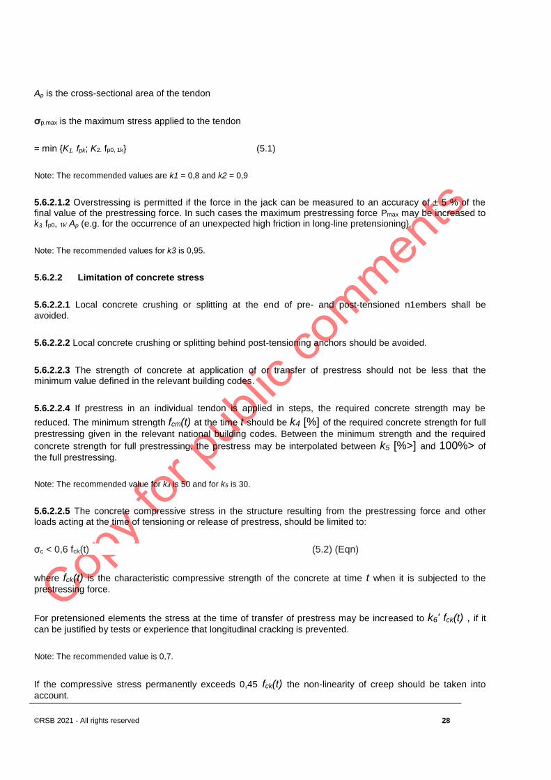
Ap is the cross-sectional area of the tendon
σp,max is the maximum stress applied to the tendon
= min {K1. fpk; K2. fp0, 1k} (5.1)
Note: The recommended values are k1 = 0,8 and k2 = 0,9
5.6.2.1.2 Overstressing is permitted if the force in the jack can be measured to an accuracy of ± 5 % of the final value of the prestressing force. In such cases the maximum prestressing force Pmax may be increased to k3·fp0, 1k’ Ap (e.g. for the occurrence of an unexpected high friction in long-line pretensioning).
Note: The recommended values for k3 is 0,95.
5.6.2.2 Limitation of concrete stress
5.6.2.2.1 Local concrete crushing or splitting at the end of pre- and post-tensioned n1embers shall be avoided.
5.6.2.2.2 Local concrete crushing or splitting behind post-tensioning anchors should be avoided.
5.6.2.2.3 The strength of concrete at application of or transfer of prestress should not be less that the minimum value defined in the relevant building codes.
5.6.2.2.4 If prestress in an individual tendon is applied in steps, the required concrete strength may be
reduced. The minimum strength fcm(t) at the time t should be k4 [%] of the required concrete strength for full
prestressing given in the relevant national building codes. Between the minimum strength and the required
concrete strength for full prestressing, the prestress may be interpolated between k5 [%>] and 100%> of
the full prestressing.
Note: The recommended value for k4 is 50 and for k5 is 30.
5.6.2.2.5 The concrete compressive stress in the structure resulting from the prestressing force and other loads acting at the time of tensioning or release of prestress, should be limited to:
σc < 0,6 fck(t) (5.2) (Eqn)
where fck(t) is the characteristic compressive strength of the concrete at time t when it is subjected to the
prestressing force.
For pretensioned elements the stress at the time of transfer of prestress may be increased to k6' fck(t) , if it can be justified by tests or experience that longitudinal cracking is prevented.
Note: The recommended value is 0,7.
If the compressive stress permanently exceeds 0,45 fck(t) the non-linearity of creep should be taken into
account.

DRS 142: 2021
29 ©RSB 2021- All rights reserved
5.6.2.3 Measurements
In post-tensioning the prestressing force and the related elongation of the tendon shall be checked by measurements and the actual losses due to friction shall be controlled.
5.6.3 Prestress force
5.6.3.1 At a given time t and distance x (or arc length) from the active end of the tendon the mean prestress
force Pm,t(x) is equal to the maximum force Pmax imposed at the active end, minus the immediate losses and the time dependent losses (see below). Absolute values are considered for all the losses.
5.6.3.2 The value of the initial prestress force Pmo(x) (at time t = t0) applied to the concrete immediately after
tensioning and anchoring (post-tensioning) or after transfer of prestressing (pre-tensioning) is obtained by subtracting from the force at tensioning Pmax the immediate losses ΔPi(x) and should not exceed the following value:
Pmo(x) = Ap.
Pm0(x) = Ap . σp,m0(x) (5.3)
where:
σpmo(x) is the stress in the tendon immediately after tensioning or transfer
= min { K7 ' fpk; kgfpo,1k}
Note: The recommended value for k7 is 0,75 and for k8 is 0,85
5.6.3.3 When determining the immediate losses ΔPi(x) the following immediate influences should be considered for pre-tensioning and post-tensioning where relevant (see 5.6.4 and 5.6.5)
a) losses due to elastic deformation of concrete ΔPel
b) losses due to short term relaxation ΔPr
c) losses due to friction ΔPµ(x)
d) losses due to anchorage slip ΔPsi
5.6.3.4 The mean value of the prestress force Pm,t(x) at the time t > t0 should be determined with respect to
the prestressing method. In addition to the immediate losses given in 5.6.3.3 the time dependent losses of prestress ΔPc+s+r(x) (see 5.6.5.4) as a result of creep and shrinkage of the concrete and the long term
relaxation of the prestressing steel should be considered and Pm,t(x)= Pmo(x) - ΔPc+s+r(x).
5.6.4 Immediate losses of prestress for pre-tensioning
5.6.4.1 The following losses occurring during pre-tensioning should be considered:
©RSB 2021 - All rights reserved 30
(i) during the stressing process: loss due to friction at the bends (in the case of curved wires or strands) and losses due to wedge draw-in of the anchorage devices.
(ii) before the transfer of prestress to concrete: loss due to relaxation of the pretensioning tendons during the period which elapses between the tensioning of the tendons and prestressing of the concrete.
Note: In case of heat curing, losses due to shrinkage and relaxation are modified and should be assessed accordingly; direct thermal effect should also be considered.
(iii) at the transfer of prestress to concrete: loss due to elastic deformation of concrete as the result of the action of pre-tensioned tendons when they are released from the anchorages.
5.6.5 Immediate losses of prestress for post-tensioning
5.6.5.1 Losses due to the instantaneous deformation of concrete
5.6.5.1.1 Account should be taken of the loss in tendon force corresponding to the deformation of concrete, taking account the order in which the tendons are stressed.
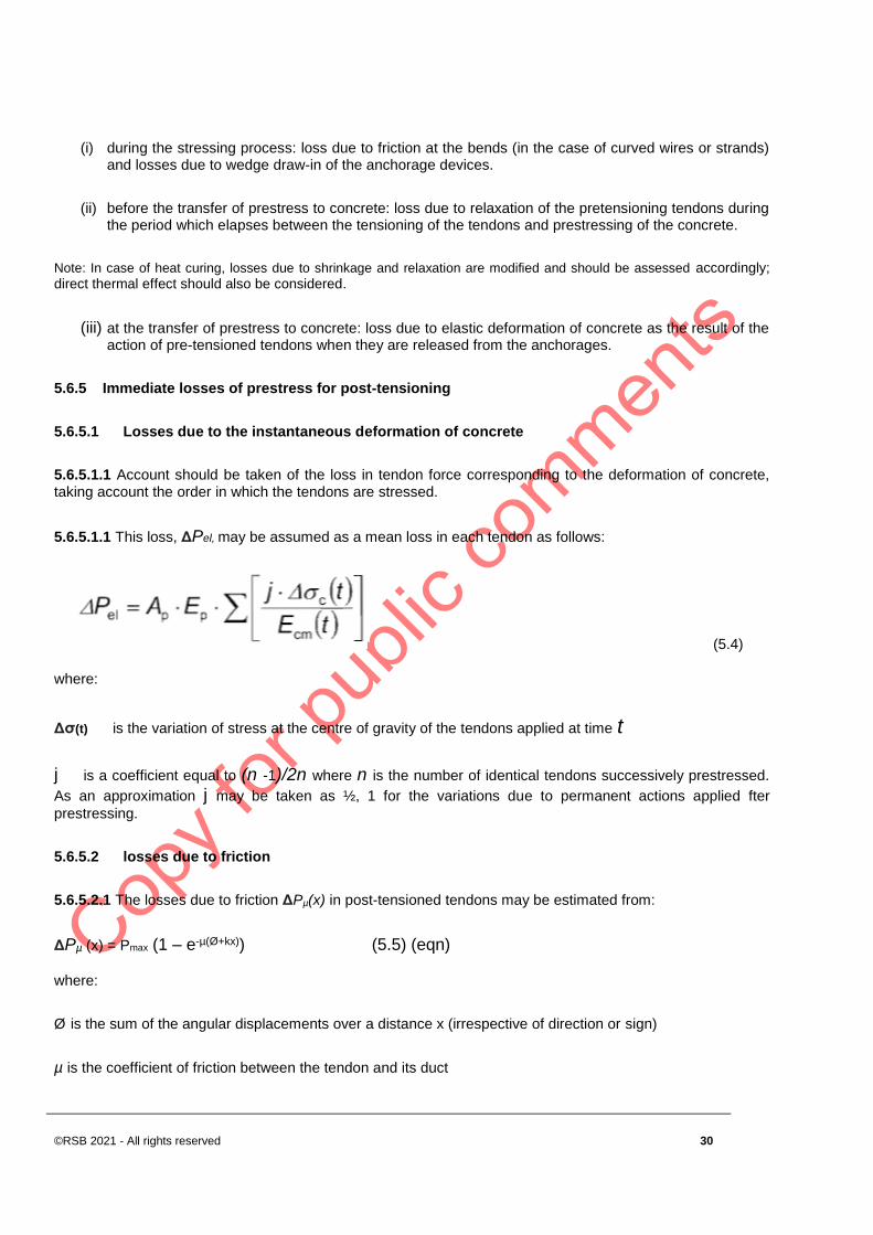
5.6.5.1.1 This loss, ΔPel, may be assumed as a mean loss in each tendon as follows:
(5.4)
where:
Δσ(t) is the variation of stress at the centre of gravity of the tendons applied at time t
j is a coefficient equal to (n -1)/2n where n is the number of identical tendons successively prestressed.
As an approximation j may be taken as ½, 1 for the variations due to permanent actions applied fter
prestressing.
5.6.5.2 losses due to friction
5.6.5.2.1 The losses due to friction ΔPµ(x) in post-tensioned tendons may be estimated from:
ΔPµ (x) = Pmax (1 – e-µ(Ø+kx)) (5.5) (eqn)
where:
Ø is the sum of the angular displacements over a distance x (irrespective of direction or sign)
µ is the coefficient of friction between the tendon and its duct
DRS 142: 2021
31 ©RSB 2021- All rights reserved
k is an unintentional angular displacement for internal tendons (per unit length)
x is the distance along the tendon from the point where the prestressing force is equal to Pmax (the force at the active end during tensioning)
The values f-L and k are given in the relevant building codes. The value f-L depends on the surface
characteristics of the tendons and the duct, on the presence of rust, on the elongation of the tendon and on the tendon profile.
The value k for unintentional angular displacement depends on the quality of workmanship, on the distance
between tendon supports, on the type of duct or sheath employed, and on the degree of vibration used in placing the concrete.
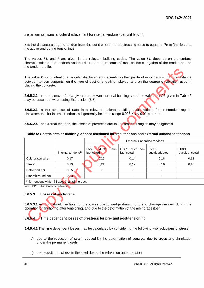
5.6.5.2.2 In the absence of data given in a relevant national building code, the values for /-L given in Table 5
may be assumed, when using Expression (5.5).
5.6.5.2.3 In the absence of data in a relevant national building code, values for unintended regular displacements for internal tendons will generally be in the range 0,005 < k < 0,01 per metre.
5.6.5.2.4 For external tendons, the losses of prestress due to unintentional angles may be ignored.
Table 5: Coefficients of friction p of post-tensioned internal tendons and external unbonded tendons
internal tendons1)
External unbonded tendons
Steel duct/ non
lubricated
HDPE duct/ non
lubricated
Steel
duct/lubricated
HDPE
duct/lubricated
Cold drawn wire 0,17 0,25 0,14 0,18 0,12
Strand 0,19 0,24 0,12 0,16 0,10
Deformed bar 0,65 - - - -
Smooth round bar 0,33 - - - -
1) for tendons which fill about half of the duct
Note: HDPE – High density polyethylene
5.6.5.3 Losses at anchorage
5.6.5.3.1 Account should be taken of the losses due to wedge draw-in of the anchorage devices, during the operation of anchoring after tensioning, and due to the deformation of the anchorage itself.
5.6.5.4 Time dependent losses of prestress for pre- and post-tensioning
5.6.5.4.1 The time dependent losses may be calculated by considering the following two reductions of stress:
a) due to the reduction of strain, caused by the deformation of concrete due to creep and shrinkage, under the permanent loads:
b) the reduction of stress in the steel due to the relaxation under tension.
©RSB 2021 - All rights reserved 32
Note: The relaxation of steel depends on the concrete deformation due to creep and shrinkage. This interaction can
generally and approximately be taken into account by a reduction factor 0,8.
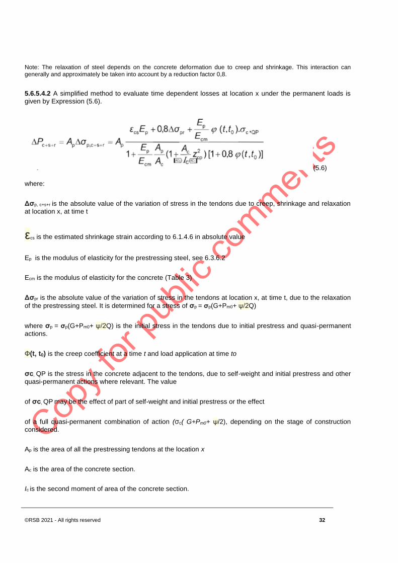
5.6.5.4.2 A simplified method to evaluate time dependent losses at location x under the permanent loads is given by Expression (5.6).
(5.6)
where:
Δσp, c+s+r is the absolute value of the variation of stress in the tendons due to creep, shrinkage and relaxation
at location x, at time t
εcs is the estimated shrinkage strain according to 6.1.4.6 in absolute value
Ep is the modulus of elasticity for the prestressing steel, see 6.3.6.2
Ecm is the modulus of elasticity for the concrete (Table 3)
Δσpr is the absolute value of the variation of stress in the tendons at location x, at time t, due to the relaxation
of the prestressing steel. It is determined for a stress of σp = σp(G+Pm0+ ψ/2Q)
where σp = σp(G+Pm0+ ψ/2Q) is the initial stress in the tendons due to initial prestress and quasi-permanent
actions.
Φ(t, t0) is the creep coefficient at a time t and load application at time to
σc, QP is the stress in the concrete adjacent to the tendons, due to self-weight and initial prestress and other
quasi-permanent actions where relevant. The value
of σc, QP may be the effect of part of self-weight and initial prestress or the effect
of a full quasi-permanent combination of action (σc( G+Pm0+ ψ/2), depending on the stage of construction
considered.
Ap is the area of all the prestressing tendons at the location x
Ac is the area of the concrete section.
Ic is the second moment of area of the concrete section.

DRS 142: 2021
33 ©RSB 2021- All rights reserved
Zcp is the distance between the centre of gravity of the concrete section and the tendons
5.6.5.4.3 Compressive stresses and the corresponding strains given in Expression (5.6) should be used with a positive sign.
5.6.5.4.4 Expression (5.6) applies for bonded tendons when local values of stresses are used and for unbonded tendons when mean values of stresses are used. The mean values should be calculated between straight sections limited by the idealised deviation points for external tendons or along the entire length in case of internal tendons.
5.6.6 Consideration of prestress in analysis
5.6.6.1 Second order moments can arise from pre-stressing with external tendons.
5.6.6.2 Moments from secondary effects of pre-stressing arise only in statically indeterminate structures.
5.6.6.3 For linear analysis both the primary and secondary effects of prestressing should be applied before any redistribution of forces and moments is considered (see 8.3).
5.6.6.4 In plastic and non-linear analysis the secondary effect of prestress may be treated as additional plastic rotations which should then be included in the check of rotation capacity.
5.6.6.5 Rigid bond between steel and concrete may be assumed after grouting of post-tensioned tendons. However before grouting the tendons should be considered as unbonded.
5.6.6.6 External tendons may be assumed to be straight between deviators.
5.6.7 Effects of prestressing at ultimate limit state
5.6.7.1 In general the design value of the prestressing force may be determined by
Pd,t(x) = (Ꝩp,Pm,t(x) (see 5.6.3.5 for the definition of Pm,t(x)) and 5.7.2.2 for Ꝩp.
5.6.7.2 For prestressed members with permanently unbonded tendons, it is generally necessary to take the deformation of the whole member into account when calculating the increase of the stress in the prestressing steel. If no detailed calculation is made, it may be assumed that the increase of the stress from the effective prestress to the stress in the ultimate limit state is
Δσp, ULS.
Note: The value of The recommended value for Δσp, ULS is 100 MPa.
5.6.7.3 If the stress increase is calculated using the deformation state of the whole member the mean values of the material properties should be used. The design value of the stress increase
Δσpd = Δσp . ꝨΔP should be determined by applying partial safety factors ꝨΔP, sup and ꝨΔP, inf. respectively.

©RSB 2021 - All rights reserved 34
Note: The recommended values for ꝨΔP, sup and ꝨΔP, inf. are 1,2 and 0,8 respectively. If linear analysis with uncracked sections is applied, a lower limit of deformations may be assumed and the recommended value for both ꝨΔP, sup and ꝨΔP,
inf. is 1,0.
5.6.8 Effects of prestressing at serviceability limit state and limit state of fatigue
5.6.8.1 For serviceability and fatigue calculations allowance shall be made for possible variations in prestress. Two characteristic values of the pre-stressing force at the serviceability limit state are estimated from:
Pk,sup = rsup Pm,t (x)
Pk,inf = rinf Pm,t(x)
where:
Pk,sup is the upper characteristic value
Pk,inf is the lower characteristic value
5.6.9 Shrinkage and creep
5.6.9.1 Shrinkage and creep are time-dependent properties of concrete. Their effects should generally be taken into account for the verification of serviceability limit states.
5.6.9.2 The effects of shrinkage and creep should be considered at ultimate limit states only where their effects are significant, for example in the verification of ultimate limit states of stability where second order effects are of importance. In other cases, these effects need not be considered for ultimate limit states, provided that ductility and rotation capacity of the elements are sufficient.
5.6.9.3 When creep is taken into account; its design effects should be evaluated under the quasi permanent combination of actions irrespective of the design situation considered i.e. persistent, transient or accidental.
NOTE In most cases; the effects of creep may be evaluated under permanent loads and the mean value of prestress
5.6.10 Deformations of concrete
5.6.10.1 The consequences of deformation due to temperature, creep and shrinkage shall be considered in design.
5.6.10.2 The influence of these effects is normally accommodated by complying with the application rules of this Standard. Consideration should also be given to:
a) minimising deformation and cracking due to early-age movement, creep and shrinkage through the composition of the concrete mix;
b) minimising restraints to deformation by the provision of bearings or joints;
c) if restraints are present, ensuring that their influence is taken into account in design

DRS 142: 2021
35 ©RSB 2021- All rights reserved
5.6.11 Geometric data
5.6.11.1 General
5.6.11.1.1 Geometric data shall be represented by their characteristic values, or (e.g. the case of imperfections) directly by their design values. 5.6.11.1.2 The dimensions specified in the design may be taken as characteristic values.
5.6.11.1.3 Where their statistical distribution is sufficiently known, values of geometrical quantities that correspond to a prescribed fractile of the statistical distribution may be used.
5.6.11.1.4 Tolerances for connected parts that are made from different materials shall be mutually compatible.
5.6.11.2 Supplementary requirements for cast in place piles
5.6.11.2.1 Uncertainties related to the cross-section of cast in place piles and concreting procedures shall be allowed for in design.
5.6.11.2.2 In the absence of other provisions the diameter used in design calculations, of cast in place piles without permanent casing should be taken as:
- if dnom < 400 mm d = dnom - 20 mm
- if 400 S;; dnom S; 1000 mm d = 0,95.dnom
- if dnom > 1000 mm d = dnom - 50 mm
Where dnom is the nominal diameter of the pile.
5.7 Verification by the partial factor method
5.7.1 General
The rules for the partial factor method are given in RS 112..
5.7.2 Design values
5.7.2.1 Partial factor for shrinkage action
Where consideration of shrinkage actions is required for ultimate limit state a partial factor, γSH, should be used. The recommended value for γSH is 1.0.

©RSB 2021 - All rights reserved 36
5.7.2.2 Partial factors for prestress
5.7.2.2.1 Prestress in most situations is intended to be favourable and for the ultimate limit state verification the value of γP,fav should be used. The design value of prestress may be based on the mean value of the
prestressing force (see RS 112). The recommended value for P,fav is 1.0. This value can also be used for fatigue verification.
5.7.2.2.2 In the verification of the limit state for stability with external prestress, where an increase of the value
of prestress can be unfavourable, P,unfav should be used. The recommended value for global analysis is 1.3.
5.7.2.2.3 In the verification of local effects ;P,unfav should also be used. The recommended value of P,unfav is 1.2.
5.7.2.3 Partial factor for fatigue loads
The partial factor for fatigue loads is F,fat . The recommended value of F,fat is 1.0.
5.7.2.4 Partial factors for materials
5.7.2.4.1 Partial factors for materials for ultimate limit states, C and S should be used. The recommended values for ‘persistent and transient’ and ‘accidental, design situations are given in Table 2.
5.7.2.4.2 For fatigue verification the partial factors for persistent design situations given in Table 2 are
recommended for the values of C,fat and S,fat.
5.7.2.4.3 When assessing the strength of a structure or of any part thereof, take the appropriate values of γm as follows:
a) reinforcement: γm = 1.15;
b) concrete in flexure or axial load: γm = 1.50;
c) shear strength without shear reinforcement and shear taken by concrete in combination with shear reinforcement: γm = 1.40;
d) bond strength: γm = 1.40;
e) others (e.g. bearing stresses): γm > 1.50.
NOTE When considering the effects of excessive loads or localized damage, take values of γm as 1.3 for concrete and 1.0
for steel.
Table 2 — Partial factors for materials for ultimate limit states
Design situations C for concrete S for reinforcing steel S for prestressing steel
Persistent and transient 1.5 1.15 1.15
Accidental 1.2 1.0 1.0
DRS 142: 2021
37 ©RSB 2021- All rights reserved
5.7.2.4.4 The values for partial factors for materials for serviceability limit state verification should be taken as those given in the particular clauses of this standard. The recommended value for situations not covered by particular clauses of this standard is 1.0.
5.7.2.4.5 Lower values of C and S may be used if justified by measures reducing the uncertainty in the calculated resistance.
5.7.2.5 Partial factors for materials for foundations
5.7.2.5.1 Design values of strength properties of the ground should be calculated in accordance with RS 112
5.7.2.5.2 The partial factor for concrete γC given in 5.7.2.4.1 should be multiplied by a factor, kf, for calculation of design resistance of cast in place piles without permanent casing. The recommended value of kf is 1.1.
5.7.3 Combinations of actions
5.7.3.1 The general formats for combinations of actions for the ultimate and serviceability limit states are given in RS 112.
5.7.3.2 For each permanent action either the lower or the upper design value (whichever gives the more unfavourable effect) should be applied throughout the structure (e.g. self-weight in a structure).
5.7.4 Verification of static equilibrium - EQU
The reliability format for the verification of static equilibrium also applies to design situations of EQU, such as holding down devices or the verification of the uplift of bearings for continuous beams.
5.8 Design assisted by testing
5.8.1 The design of structures or structural elements may be assisted by testing.
NOTE Information is given RS 112.
5.9 Supplementary requirements for foundations
5.9.1 Where ground-structure interaction has significant influence on the action effects in the structure, the properties of the soil and the effects of the interaction shall be taken into account in accordance with RS 113.
5.9.2 Where significant differential settlements are likely, their influence on the action effects in the structure should be checked.
5.9.3 Concrete foundations should be sized in accordance with RS 113.

©RSB 2021 - All rights reserved 38
5.9.4 Where relevant, the design should include the effects of phenomena such as subsidence, heave, freezing, thawing, erosion, etc.
5.10 Requirements for fastenings
The local and structural effects of fasteners should be considered. The requirements for the design of
fastenings for use in concrete should include the following types of fasteners:
a) headed anchors,
b) expansion anchors,
c) undercut anchors,
d) concrete screws,
e) bonded anchors,
f) bonded expansion anchors and
g) bonded undercut anchors.
NOTE Design of Fastenings for use in concrete includes the local transmission of loads into the structure.
6 Materials
6.1 Concrete
6.1.1 General
The following clauses give principles and rules for normal and high strength concrete.
6.1.2 Strength
6.1.2.1 The compressive strength of concrete is denoted by concrete strength classes which relate to the characteristic (5 %) cylinder strength fck or the cube strength fck,cube, in accordance with RS ISO 22965-1 & 2..
6.1.2.2 The strength classes in this code are based on the characteristic cylinder strength fck determined at 28 days with a maximum value of Cmax. The recommended value of Cmax is C90/105.
6.1.2.3 The characteristic strengths for fck and the corresponding mechanical characteristics necessary for design, are given in Table 2.
6.1.2.4 In certain situations (e.g. prestressing) it may be appropriate to assess the compressive strength for concrete before or after 28 days depending on the conditions under which test specimens were stored. If the
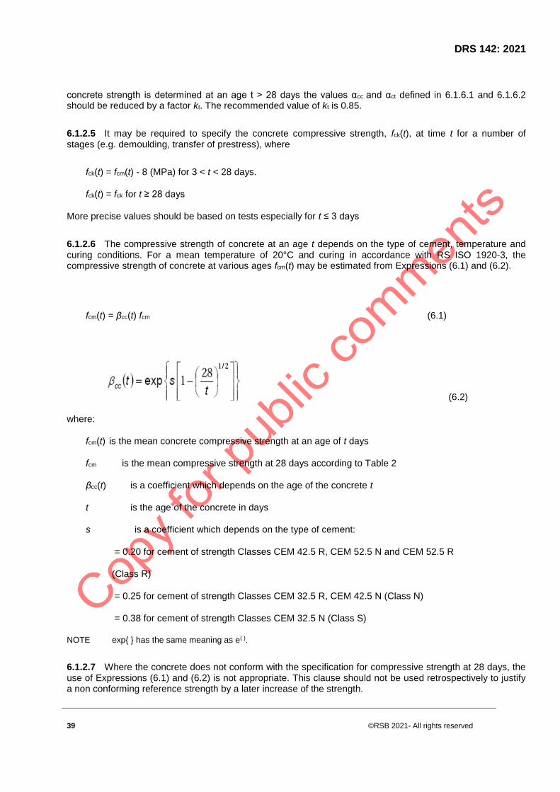
DRS 142: 2021
39 ©RSB 2021- All rights reserved
concrete strength is determined at an age t > 28 days the values αcc and αct defined in 6.1.6.1 and 6.1.6.2 should be reduced by a factor kt. The recommended value of kt is 0.85.
6.1.2.5 It may be required to specify the concrete compressive strength, fck(t), at time t for a number of stages (e.g. demoulding, transfer of prestress), where
fck(t) = fcm(t) - 8 (MPa) for 3 < t < 28 days.
fck(t) = fck for t ≥ 28 days
More precise values should be based on tests especially for t ≤ 3 days
6.1.2.6 The compressive strength of concrete at an age t depends on the type of cement, temperature and curing conditions. For a mean temperature of 20°C and curing in accordance with RS ISO 1920-3, the compressive strength of concrete at various ages fcm(t) may be estimated from Expressions (6.1) and (6.2).
fcm(t) = βcc(t) fcm (6.1)
(6.2)
where:
fcm(t) is the mean concrete compressive strength at an age of t days
fcm is the mean compressive strength at 28 days according to Table 2
βcc(t) is a coefficient which depends on the age of the concrete t
t is the age of the concrete in days
s is a coefficient which depends on the type of cement:
= 0.20 for cement of strength Classes CEM 42.5 R, CEM 52.5 N and CEM 52.5 R
(Class R)
= 0.25 for cement of strength Classes CEM 32.5 R, CEM 42.5 N (Class N)
= 0.38 for cement of strength Classes CEM 32.5 N (Class S)
NOTE exp{ } has the same meaning as e( ).
6.1.2.7 Where the concrete does not conform with the specification for compressive strength at 28 days, the use of Expressions (6.1) and (6.2) is not appropriate. This clause should not be used retrospectively to justify a non conforming reference strength by a later increase of the strength.

©RSB 2021 - All rights reserved 40
6.1.2.8 The tensile strength refers to the highest stress reached under concentric tensile loading. For the flexural tensile strength reference should be made to 6.1.8 (1).
6.1.2.9 Where the tensile strength is determined as the splitting tensile strength, fct,sp, an approximate value of the axial tensile strength, fct, may be taken as:
fct = 0,9fct,sp (6.3)
6.1.2.10 The development of tensile strength with time is strongly influenced by curing and drying conditions as well as by the dimensions of the structural members. As a first approximation it may be assumed that the tensile strength fctm(t) is equal to:
fctm(t)=(βcc(t))α.fctm (6.4)
where
βcc(t) follows from Expression (6.2) and
α = 1 for t < 28
α = 2/3 for t ≥ 28. The values for fctm are given in Table 2.
NOTE Where the development of the tensile strength with time is important; it is recommended that tests are carried
out taking into account the exposure conditions and the dimensions of the structural member.
6.1.3 Elastic deformation
6.1.3.1 The elastic deformations of concrete largely depend on its composition (especially the aggregates). The values given in this Standard should be regarded as indicative for general applications. However, they should be specifically assessed if the structure is likely to be sensitive to deviations from these general values.
6.1.3.2 The modulus of elasticity of a concrete is controlled by the moduli of elasticity of its components. Approximate values for the modulus of elasticity Ecm, secant value between σc = 0 and 0.4fcm, for concretes with quartzite aggregates, are given in Table 2. For sandstone aggregates the value should be reduced by 30 %. For basalt aggregates the value should be increased by 20 %.
Table 2 — Strength and deformation characteristics for concrete
Strength classes for concrete Analytical relation
/ Explanation
fck (MPa) 12 16 20 25 30 35 40 45 50 55 60 70 80 90
fck,cube
(MPa)
15 20 25 30 37 45 50 55 60 67 75 85 95 105 2.8
fcm (MPa) 20 24 28 33 38 43 48 53 58 63 68 78 88 98 fcm = fck+8 (MPa)
fctm (MPa) 1.6 1.9 2.2 2.6 2.9 3.2 3.5 3.8 4.1 4.2 4.4 4.6 4.8 5.0 fctm=0.30×fck(2/3)
≤C50/60
fctm=2.12·In(1+(fcm/10)
) > C50/60
fctk,0,05
(MPa)
1.1 1.3 1.5 1.8 2.0 2.2 2.5 2.7 2.9 3.0 3.1 3.2 3.4 3.5 fctk;0,05 = 0,7×fctm
5% fractile

DRS 142: 2021
41 ©RSB 2021- All rights reserved
fctk,,095
(MPa)
2.0 2.5 2.9 3.3 3.8 4.2 4.6 4.9 5.3 5.5 5.7 6.0 6.3 6.6 fctk;0.95 = 1,3×fctm
95 % fractile
Ecm (GPa) 27 29 30 31 33 34 35 36 37 38 39 41 42 44 Ecm = 22[(fcm)/10]0.3
(fcm in MPa)
c1 (0/00) 1.8 1.9 2.0 2.1 2.2 2.25 2.3 2.4 2.45 2.5 2.6 2.7 2.8 2.8 see Figure 3.2
εc1 (0/00) = 0.7 fcm0.31
cu1(0/00) 3.5 2.2 3.0 2.8 2.8 2.8 see Figure 2
for fck ≥ 50 Mpa
εc1(0/00)=2.8+27[(98-
fcm)/100]4
cu2 (0/00) 2.0 2.2 2.3 2.4 2.5 2.6 see Figure 3
for fck ≥ 50 Mpa
εc2(0/00)=2.0+0.085(fc
k-50)0.53
cu2 (0/00) 3.5 3.1 2.9 2.7 2.6 2.6 see Figure 3
for fck ≥ 50 Mpa
cu2(0/00)=2.6+35[(90-
fck)/100]4
N 2.0 1.75 1.6 1.45 1.4 1.4 for fck≥ 50 Mpa
n=1.4+23.4[(90-
fck)/100]4
cu3 (0/00) 1.75 1.8 1.9 2.0 2.2 2.3 see Figure 4
for fck≥ 50 Mpa
εc3(0/00)=1.75+0.55[(fc
k-50)/40]
cu3 (0/00) 3.5 3.1 2.9 2.7 2.6 2.6 see Figure 4
for fck ≥ 50 Mpa
εcu3(0/00)=2.6+35[(90-
fck)/100]4
6.1.3.3 Variation of the modulus of elasticity with time can be estimated by:
Ecm(t) = (fcm(t) / fcm)0.3 Ecm (6.5)
Where
Ecm(t) and fcm(t) are the values at an age of t days and
Ecm and fcm are the values determined at an age of 28 days.
The relation between fcm(t) and fcm follows from Expression (6.1).
6.1.3.4 Poisson’s ratio may be taken equal to 0.2 for uncracked concrete and 0 for cracked concrete.
6.1.3.5 Unless more accurate information is available, the linear coefficient of thermal expansion may be taken equal to 10 .10-6 K -1.

©RSB 2021 - All rights reserved 42
6.1.4 Creep and shrinkage
6.1.4.1 Creep and shrinkage of the concrete depend on the ambient humidity, the dimensions of the element and the composition of the concrete. Creep is also influenced by the maturity of the concrete when the load is first applied and depends on the duration and magnitude of the loading.
6.1.4.2 The creep coefficient, εcc (t,t0) is related to Ec, the tangent modulus, which may be taken as 1.05 Ecm.
Where great accuracy is not required, the value found from Figure 1 may be considered as the creep coefficient, provided that the concrete is not subjected to a compressive stress greater than 0.45 fck (t0 ) at an age t0, the age of concrete at the time of loading.
6.1.4.3 The creep deformation of concrete εcc(∞,t0) at time t = ∞ for a constant compressive stress σc applied at the concrete age t0, is given by:
εcc (∞,t0) = φ (∞,t0). (σc /Ec) (6.6)
6.1.4.4 When the compressive stress of concrete at an age t0 exceeds the value 0.45 fck(t0) then creep non-linearity should be considered. Such a high stress can occur as a result of pretensioning, e.g. in precast concrete members at tendon level. In such cases the non-linear notional creep coefficient should be obtained as follows:
φnl= φ(∞, t0) exp (1.5 (kσ – 0,45)) (6.7)
where:
φnl is the non-linear notional creep coefficient, which replaces φ (∞, t0)
kσ is the stress-strength ratio σc/f (t0), where σc is the compressive stress and
f 0 (t ) is the characteristic concrete compressive strength at the time of loading
a) inside conditions - RH = 50%

DRS 142: 2021
43 ©RSB 2021- All rights reserved
NOTE
a) intersection point between lines 4 and 5 can also be above point 1
b) for t0 > 100 it is sufficiently accurate to assume t0 = 100 (and use the tangent line)
b) outside conditions - RH = 80%
Figure 1 — Method for determining the creep coefficient φ(∞, t0) for concrete under normal environmental conditions
6.1.4.5 The values given in Figure 1 are valid for ambient temperatures between -40 °C and +40 °C and a mean relative humidity between RH = 40% and RH = 100%. The following symbols are used:
φ (∞, t0) is the final creep coefficient
t0 is the age of the concrete at time of loading in days
h0is the notional size = 2Ac /u, where Ac is the concrete cross-sectional area and u is the perimeter of that part which is exposed to drying
S is Class S, according to 6.1.2.6
N is Class N, according to 6.1.2.6
R is Class R, according to 6.1.2.6
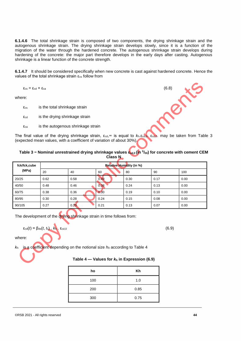
©RSB 2021 - All rights reserved 44
6.1.4.6 The total shrinkage strain is composed of two components, the drying shrinkage strain and the autogenous shrinkage strain. The drying shrinkage strain develops slowly, since it is a function of the migration of the water through the hardened concrete. The autogenous shrinkage strain develops during hardening of the concrete: the major part therefore develops in the early days after casting. Autogenous shrinkage is a linear function of the concrete strength.
6.1.4.7 It should be considered specifically when new concrete is cast against hardened concrete. Hence the values of the total shrinkage strain εcs follow from
εcs = εcd + εca (6.8)
where:
εcs is the total shrinkage strain
εcd is the drying shrinkage strain
εca is the autogenous shrinkage strain
The final value of the drying shrinkage strain, εcd,∞ is equal to kh.εcd,0. εcd,0. may be taken from Table 3 (expected mean values, with a coefficient of variation of about 30%).
Table 3 − Nominal unrestrained drying shrinkage values εcd,0 (in 0/00) for concrete with cement CEM Class N
fck/fck,cube
(MPa)
Relative Humidity (in %)
20 40 60 80 90 100
20/25 0.62 0.58 0.49 0.30 0.17 0.00
40/50 0.48 0.46 0.38 0.24 0.13 0.00
60/75 0.38 0.36 0.30 0.19 0.10 0.00
80/95 0.30 0.28 0.24 0.15 0.08 0.00
90/105 0.27 0.25 0.21 0.13 0.07 0.00
The development of the drying shrinkage strain in time follows from:
εcd(t) = βds(t, ts) . kh . εcd,0 (6.9)
where:
kh is a coefficient depending on the notional size h0 according to Table 4
Table 4 — Values for kh in Expression (6.9)
ho Kh
100 1.0
200 0.85
300 0.75
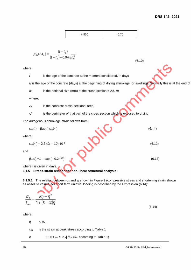
DRS 142: 2021
45 ©RSB 2021- All rights reserved
≥ 500 0.70
(6.10)
where:
t is the age of the concrete at the moment considered, in days
ts is the age of the concrete (days) at the beginning of drying shrinkage (or swelling). Normally this is at the end of curing.
h0 is the notional size (mm) of the cross-section = 2Ac /u
where:
Ac is the concrete cross-sectional area
U is the perimeter of that part of the cross section which is exposed to drying
The autogenous shrinkage strain follows from:
εca (t) = βas(t) εca(∞) (6.11)
where:
εca(∞) = 2,5 (fck – 10) 10-6 (6.12)
and
βas(t) =1 – exp (– 0,2t 0,5) (6.13)
where t is given in days.
6.1.5 Stress-strain relation for non-linear structural analysis
6.1.5.1 The relation between σc and εc shown in Figure 2 (compressive stress and shortening strain shown as absolute values) for short term uniaxial loading is described by the Expression (6.14):
(6.14)
where:
η εc /εc1
εc1 is the strain at peak stress according to Table 1
k 1.05 Ecm × |εc1| /fcm (fcm according to Table 1)
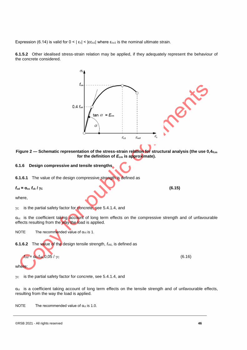
©RSB 2021 - All rights reserved 46
Expression (6.14) is valid for 0 < | εc| < |εcu1| where εcu1 is the nominal ultimate strain.
6.1.5.2 Other idealised stress-strain relation may be applied, if they adequately represent the behaviour of the concrete considered.
Figure 2 — Schematic representation of the stress-strain relation for structural analysis (the use 0,4fcm for the definition of Ecm is approximate).
6.1.6 Design compressive and tensile strengths
6.1.6.1 The value of the design compressive strength is defined as
fcd = αcc fck / C (6.15)
where,
C is the partial safety factor for concrete, see 5.4.1.4, and
αcc is the coefficient taking account of long term effects on the compressive strength and of unfavourable effects resulting from the way the load is applied.
NOTE The recommended value of αcc is 1.
6.1.6.2 The value of the design tensile strength, fctd, is defined as
fctd = αct fctk,0,05 / C (6.16)
where:
C is the partial safety factor for concrete, see 5.4.1.4, and
αct is a coefficient taking account of long term effects on the tensile strength and of unfavourable effects, resulting from the way the load is applied.
NOTE The recommended value of αct is 1.0.

DRS 142: 2021
47 ©RSB 2021- All rights reserved
6.1.7 Stress-strain relations for the design of cross-sections
6.1.7.1 For the design of cross-sections, the following stress-strain relationship may be used, see Figure 3 (compressive strain shown positive):
for 0 c c2 ( 6.17)
(6.18)
Where,
n is the exponent according to Table 2
εc2 is the strain at reaching the maximum strength according to Table 2.
εcu2 is the ultimate strain according to Table 2.
Figure 3 — Parabola-rectangle diagram for concrete under compression
6.1.7.2 Other simplified stress-strain relationships may be used if equivalent to or more conservative than the one defined in 6.1.7.1, for instance bi-linear according to Figure 4 (compressive stress and shortening strain shown as absolute values) with values of εc3 and εcu3 according to Table 2.
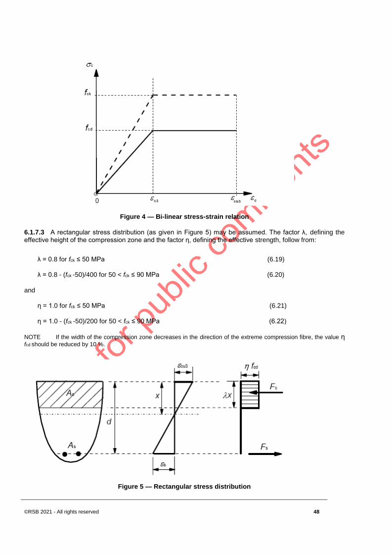
©RSB 2021 - All rights reserved 48
Figure 4 — Bi-linear stress-strain relation
6.1.7.3 A rectangular stress distribution (as given in Figure 5) may be assumed. The factor λ, defining the effective height of the compression zone and the factor η, defining the effective strength, follow from:
λ = 0.8 for fck ≤ 50 MPa (6.19)
λ = 0.8 - (fck -50)/400 for 50 < fck ≤ 90 MPa (6.20)
and
η = 1.0 for fck ≤ 50 MPa (6.21)
η = 1.0 - (fck -50)/200 for 50 < fck ≤ 90 MPa (6.22)
NOTE If the width of the compression zone decreases in the direction of the extreme compression fibre, the value η fcd should be reduced by 10 %.
Figure 5 — Rectangular stress distribution

DRS 142: 2021
49 ©RSB 2021- All rights reserved
6.1.8 Flexural tensile strength
The mean flexural tensile strength of reinforced concrete members depends on the mean axial tensile strength and the depth of the cross-section. The following relationship may be used:
fctm,fl = max {(1,6 - h/1000)fctm; fctm } (6.23)
where:
h is the total member depth in mm
fctm is the mean axial tensile strength following from Table 2.
The relation given in Expression (6.23) also applies for the characteristic tensile strength values.
6.1.9 Confined concrete
6.1.9.1 Confinement of concrete results in a modification of the effective stress-strain relationship: higher strength and higher critical strains are achieved. The other basic material characteristics may be considered as unaffected for design.
6.1.9.2 In the absence of more precise data, the stress-strain relation shown in Figure 6 (compressive strain shown positive) may be used, with increased characteristic strength and strains according to:
fck,c = fck (1,000 + 5,0 σ2/fck) for σ2 ≤ 0,05fck (6.24)
fck,c = fck (1,125 + 2,50 σ2/fck) for σ2 > 0,05fck (6.25)
εc2,c = εc2 (fck,c/fck)2 (6.26)
εcu2,c = εcu2 + 0,2 σ2/fck (6.27)
where,
σ2 (= σ3) is the effective lateral compressive stress at the ULS due to confinement and εc2 and εcu2 follow from Table 2. Confinement can be generated by adequately closed links or cross-ties, which reach the plastic
condition due to lateral extension of the concrete.
Figure 6 −Stress-strain relationship for confined concrete

©RSB 2021 - All rights reserved 50
6.2 Reinforcing steel
6.2.1 General
6.2.1.1 The following clauses give principles and rules for reinforcement which is in the form of bars, de-coiled rods, welded fabric and lattice girders. They do not apply to specially coated bars.
6.2.1.2 The requirements for the properties of the reinforcement are for the material as placed in the hardened concrete. If site operations can affect the properties of the reinforcement, then those properties shall be verified after such operations.
6.2.2 Properties
6.2.2.1 The behaviour of reinforcing steel is specified by the following properties:
a) yield strength (fyk or f0,2k)
b) maximum actual yield strength (fy,max)
c) tensile strength (ft)
d) ductility (εuk and ft/fyk)
e) bendability
f) bond characteristics
g) section sizes and tolerances
h) fatigue strength
i) weldability
j) shear and weld strength for welded fabric and lattice girders
6.2.2.2 This standard applies to ribbed and weldable reinforcement, including fabric. The permitted welding methods are given in Table 5.
NOTE The properties of reinforcement required for use with this standard are given in Annex A.
6.2.2.3 The application rules for design and detailing in this standard are valid for a specified yield strength range, fyk = 400 to 600 MPa.
6.2.2.4 The surface characteristics of ribbed bars shall be such to ensure adequate bond with the concrete.
6.2.2.5 Adequate bond may be assumed by compliance with the specification of projected rib area, fR.

DRS 142: 2021
51 ©RSB 2021- All rights reserved
NOTE Minimum values of the relative rib area, fR, are given in the Annex A.
6.2.2.6 The reinforcement shall have adequate bendability to allow the use of the minimum mandrel diameters and to allow rebending to be carried out.
NOTE For bend and rebend requirements see Annex A.
6.2.3 Strength
6.2.3.1 The yield strength fk (or the 0.2% proof stress, f0,2k) and the tensile strength ftk are defined respectively as the characteristic value of the yield load, and the characteristic maximum load in direct axial tension, each divided by the nominal cross sectional area.
6.2.4 Ductility characteristics
The reinforcement shall have adequate ductility as defined by the ratio of tensile strength to the yield stress, (ft/fy)k and the elongation at maximum force, εuk .
NOTE Values of k= (ft/fy)k and εuk for Class A, B and C are given in Annex A.
a) Hot rolled steel b) Cold worked steel
Figure 7 — Stress-strain diagrams of typical reinforcing steel (absolute values are shown for tensile stress and strain)
6.2.5 Welding
6.2.5.1 Welding processes for reinforcing bars shall be in accordance with Table 5.
Table 5 — Permitted welding processes and examples of application
Loading case Welding method Bars in tension1 Bars in compression1

©RSB 2021 - All rights reserved 52
Predominantly
static
flash-welding butt joint
manual metal arc welding
and metal arc welding with
filling electrode
butt joint with ≥ 20 mm, splice, lap, cruciform
joints3, joint with other steel members
metal arc active welding 2
splice, lap, cruciform 3 joints & joint with other
steel members
- butt joint with ≥ 20 mm
friction welding butt joint, joint with other steels
resistance spot welding lap joint 4
cruciform joint 2, 4
Not predominantly
static
flash-welding butt joint
manual metal arc welding - butt joint with ≥ 14 mm
metal arc active welding2 - butt joint with ≥ 14 mm
resistance spot welding lap joint 4
cruciform joint 2, 4
1 Only bars with approximately the same nominal diameter may be welded together.
2 Permitted ratio of mixed diameter bars ≥ 0.57
3 For bearing joints ≤ 16 mm
4 For bearing joints ≤ 28 mm
6.2.5.2 All welding of reinforcing bars shall be carried out in accordance with RS ISO 17660.
6.2.5.3 The strength of the welded joints along the anchorage length of welded fabric shall be sufficient to resist the design forces.
6.2.5.4 The strength of the welded joints of welded fabric may be assumed to be adequate if each welded joint can withstand a shearing force not less than 25 % of a force equivalent to the specified characteristic yield stress times the nominal cross sectional area. This force should be based on the area of the thicker wire if the two are different.
6.2.6 Fatigue
Where fatigue strength is required it shall be verified in accordance with RS ISO 17660.
NOTE Information is given in Annex A.
6.2.7 Design assumptions
6.2.7.1 Design should be based on the nominal cross-section area of the reinforcement and the design values derived from the characteristic values given in 6.2.2.
6.2.7.2 For normal design, the recommended value of a strain limit (εud) is 0 9εuk and that of a maximum stress (K= (ft/fy)k ) is given in Annex A.

DRS 142: 2021
53 ©RSB 2021- All rights reserved
6.2.7.3 The mean value of density may be assumed to be 7850 kg/m3
6.2.7.4 The design value of the modulus of elasticity, Es may be assumed to be 200 GPa.
6.3 Prestressing steel
6.3.1 General
6.3.1.1 This clause applies to wires, bars and strands used as prestressing tendons in concrete structures.
6.3.1.2 Prestressing tendons shall have an acceptably low level of susceptibility to stress corrosion.
6.3.1.3 For steels complying with this standard, tensile strength, 0.1% proof stress, and elongation at maximum load are specified in terms of characteristic values; these values are designated respectively fpk, fp0,1k and εuk.
6.3.1.4 Each product shall be clearly identifiable with respect to the classification system in 6.3.2
6.3.1.5 The prestressing tendons shall be classified for relaxation purposes according to 6.3.2
6.3.1.6 Each consignment shall be accompanied by a certificate containing all the information necessary for its identification with regard to (i) - (iv) in 6.3.2.2 and additional information where necessary.
6.3.1.7 There shall be no welds in wires and bars. Individual wires of strands may contain staggered welds made only before cold drawing.
6.3.2 Properties
6.3.2.1 The properties of prestressing steel are given in RS ISO 6934-1
6.3.2.2 The prestressing tendons (wires, strands and bars) shall be classified according to:
a) Strength, denoting the value of the 0.1% proof stress (fp0.1k) and the value of the ratio of tensile strength to proof strength (fpk /fp0.1k) and elongation at maximum load (εuk)
b) Class, indicating the relaxation behaviour
c) Size
d) Surface characteristics.
6.3.2.3 The actual mass of the prestressing tendons shall not differ from the nominal mass by more than the limits specified in RS ISO 6934-4
6.3.2.4 In this standard, three classes of relaxation are defined:
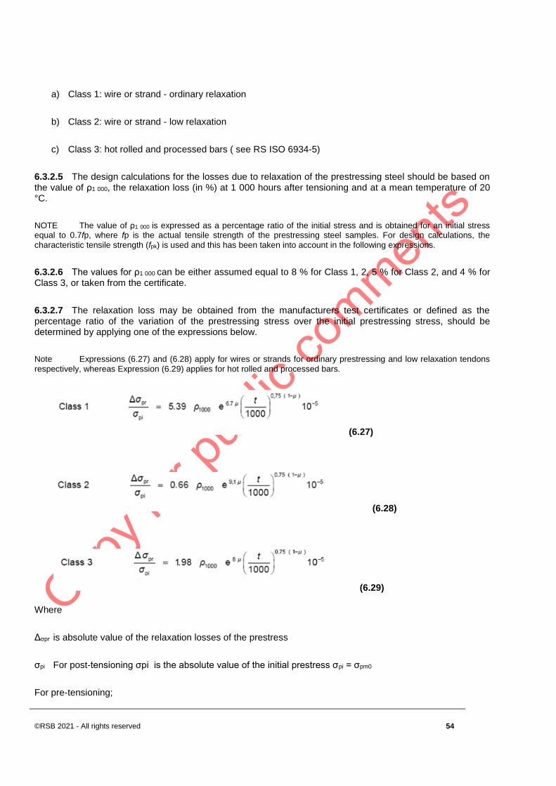
©RSB 2021 - All rights reserved 54
a) Class 1: wire or strand - ordinary relaxation
b) Class 2: wire or strand - low relaxation
c) Class 3: hot rolled and processed bars ( see RS ISO 6934-5)
6.3.2.5 The design calculations for the losses due to relaxation of the prestressing steel should be based on the value of ρ1 000, the relaxation loss (in %) at 1 000 hours after tensioning and at a mean temperature of 20 °C.
NOTE The value of ρ1 000 is expressed as a percentage ratio of the initial stress and is obtained for an initial stress equal to 0.7fp, where fp is the actual tensile strength of the prestressing steel samples. For design calculations, the
characteristic tensile strength (fpk) is used and this has been taken into account in the following expressions.
6.3.2.6 The values for ρ1 000 can be either assumed equal to 8 % for Class 1, 2, 5 % for Class 2, and 4 % for
Class 3, or taken from the certificate.
6.3.2.7 The relaxation loss may be obtained from the manufacturers test certificates or defined as the percentage ratio of the variation of the prestressing stress over the initial prestressing stress, should be determined by applying one of the expressions below.
Note Expressions (6.27) and (6.28) apply for wires or strands for ordinary prestressing and low relaxation tendons
respectively, whereas Expression (6.29) applies for hot rolled and processed bars.
(6.27)
(6.28)
(6.29)
Where
Δσpr is absolute value of the relaxation losses of the prestress
σpi For post-tensioning σpi is the absolute value of the initial prestress σpi = σpm0
For pre-tensioning;

DRS 142: 2021
55 ©RSB 2021- All rights reserved
σpi is the maximum tensile stress applied to the tendon minus the immediate losses occurred during the stressing process
t is the time after tensioning (in hours)
μ σpi /fpk, where fpk is the characteristic value of the tensile strength of the prestressing steel
ρ1 000 is the value of relaxation loss (in %), at 1 000 hours after tensioning and at a mean temperature of 20
°C.
6.3.2.8 The long term (final) values of the relaxation losses may be estimated for a time t equal to 500 000 hours (i.e. around 57 years).
6.3.2.9 Relaxation losses are very sensitive to the temperature of the steel. Where heat treatment 50 °C the relaxation losses should be verified.
6.3.3 Strength
6.3.3.1 The 0.1% proof stress (fp0.1k ) and the specified value of the tensile strength (fpk) are defined as the characteristic value of the 0.1% proof load and the characteristic maximum load in axial tension respectively, divided by the nominal cross sectional area as shown in Figure 8.
Figure 8 — Stress-strain diagram for typical prestressing steel (absolute values are shown for tensile stress and strain)
6.3.4 Ductility characteristics
6.3.4.1 The prestressing tendons shall have adequate ductility, as specified in RS ISO 6934-4.
6.3.4.2 Adequate ductility in elongation may be assumed if the prestressing tendons obtain the specified value of the elongation at maximum load given in RS ISO 6934-4

©RSB 2021 - All rights reserved 56
6.3.4.3 Adequate ductility in bending may be assumed if the prestressing tendons satisfy the requirements for bendability of RS ISO 15630-3.
6.3.4.4 Stress-strain diagrams for the prestressing tendons, based on production data, shall be prepared and made available by the producer as an annex to the certificate accompanying the consignment (see 6.3.1 9).
6.3.4.5 Adequate ductility in tension may be assumed for the prestressing tendons if fpk /fp0,1k ≥ k.
NOTE The recommended value of k is 1,1.
6.3.5 Fatigue
6.3.5.1 Prestressing tendons shall have adequate fatigue strength as per the requirements of Annex A of RS ISO 6934-1)
6.3.5.2 The fatigue stress range for prestressing tendons shall be in accordance with RS ISO 6934-1
6.3.6 Design assumptions
6.3.6.1 Structural analysis is performed on the basis of the nominal cross-section area of the prestressing steel and the characteristic values fp0.1k, fpk and εuk.
6.3.6.2 The design value for the modulus of elasticity, Ep may be assumed equal to 205 GPa for wires and bars. The actual value can range from 195 GPa to 210 GPa, depending on the manufacturing process. Certificates accompanying the consignment should give the appropriate value.
6.3.6.3 The design value for the modulus of elasticity, Ep may be assumed equal to 195 GPa for strand. The actual value can range from 185 GPa to 205 GPa, depending on the manufacturing process. Certificates accompanying the consignment should give the appropriate value.
6.3.6.4 The mean density of prestressing tendons for the purposes of design may normally be taken as 7850 kg/m3
6.3.6.5 The values given above may be assumed to be valid within a temperature range between -40 °C and +100 °C for the prestressing steel in the finished structure.
6.3.6.6.6 The design value for the steel stress, fpd, is taken as fp0.1k/γS .
NOTE The recommended value of εud is 0.9εuk. If more accurate values are not known the recommended values are εud = 0.02 and fp0.1k /fpk = 0.9.
7 Durability and cover to reinforcement
7.1 General
7.1.1 A durable structure shall meet the requirements of serviceability, strength and stability throughout its design working life, without significant loss of utility or excessive unforeseen maintenance.

DRS 142: 2021
57 ©RSB 2021- All rights reserved
7.1.2 The required protection of the structure shall be established by considering its intended use, design working life, maintenance programme and actions.
7.1.3 The possible significance of direct and indirect actions, environmental conditions and consequential effects shall be considered.
7.1.4 Corrosion protection of steel reinforcement depends on density, quality and thickness of concrete cover and cracking . The cover density and quality is achieved by controlling the maximum water/cement ratio and minimum cement content (see RS EAS 417-1) and may be related to a minimum strength class of concrete.
7.1.5 Where metal fastenings are inspectable and replaceable, they may be used with protective coatings in exposed situations. Otherwise, they should be of corrosion resistant material.
7.1.6 Further requirements to those given in this clause should be considered for special situations (e.g. for structures of temporary or monumental nature, structures subjected to extreme or unusual actions etc.).
7.2 Environmental conditions
7.2.1 Exposure conditions are chemical and physical conditions to which the structure is exposed in addition to the mechanical actions.
7.2.2 Environmental conditions are classified according to Table 6, based on RS ISO 22965-1.
7.2.3 In addition to the conditions in Table 6, particular forms of aggressive or indirect action should be considered including chemical attack arising from:
a) the use of the building or the structure (storage of liquids, etc)
b) solutions of acids or sulfate salts (RS ISO 22965, ISO 9690)
c) chlorides contained in the concrete (RS ISO 22965-1)
d) alkali-aggregate reactions (RS ISO 22965) physical attack,
e) arising from e.g.
f) temperature change
g) abrasion
h) water penetration (RS ISO 22965).

©RSB 2021 - All rights reserved 58
Table 6 — Exposure classes related to environmental conditions in accordance With RS ISO 22965
Class designation Description of the environment Informative examples where
exposure classes may occur
1 no risk of corrosion or attack
XO For concrete without reinforcement or embedded metal: all exposures
except where there is freeze/thaw, abrasion or chemical attack. For
concrete with reinforcement or
embedded metal: very dry
Concrete inside buildings with very
low air humidity
2 Corrosion induced by carbonation
XC1 Dry or permanently wet Concrete inside buildings with low air
humidity
Concrete permanently submerged in
water
XC2 Wet, rarely dry Concrete surfaces subject to long-
term watercontact
Many foundations
XC3 Moderate humidity Concrete inside buildings with
moderate or high air
humidity
External concrete sheltered from rain
XC4 Cyclic wet and dry Concrete surfaces subject to water
contact, not
within exposure class XC2
3 Corrosion induced by chlorides
XD1 Moderate humidity Concrete surfaces exposed to
airborne chlorides
XD2 Wet, rarely dry Swimming pools
Concrete components exposed to
industrial waters
containing chlorides
XD3 Cyclic wet and dry Parts of bridges exposed to spray
containing chlorides
Pavements
Car park slabs
4 Freeze/Thaw Attack
XF1 Moderate water saturation, without
de-icing
agent
Vertical concrete surfaces exposed
to rain and freezing
XF2 Moderate water saturation, with de-
icing agent
Vertical concrete surfaces of road structures exposed to freezing and
airborne de-icing agents
XF3 High water saturation, without de-
icing agents
Horizontal concrete surfaces
exposed to rain and freezing
XF4 High water saturation with de-icing
agents or
sea water
Road and bridge decks exposed to
de-icing agents
Concrete surfaces exposed to direct

DRS 142: 2021
59 ©RSB 2021- All rights reserved
spray containing de-icing agents and
freezing
splash zone of marine structures
exposed to freezing
5 Chemical attack
XA1 Slightly aggressive chemical
environment
according to RS ISO 22965, Table
A1
Natural soils and ground water
XA2 Moderately aggressive chemical
environment
according to RS ISO 22965, Table
A1
Natural soils and ground water
XA3 Highly aggressive chemical
environment
according to RS ISO 22965, Table
A1
Natural soils and ground water
7.2.4 The composition of the concrete affects both the protection of the reinforcement and the resistance of the concrete to attack. This may lead to the choice of higher strength classes than required for the structural design. In such cases the value of fctm should be associated with the higher strength in the calculation of minimum reinforcement and crack width control.
7.3 Requirements for durability
7.3.1 In order to achieve the required design working life of the structure, adequate measures shall be taken to protect each structural element against the relevant environmental actions.
7.3.2 The requirements for durability shall be included when considering the following:
a) Structural conception,
b) Material selection,
c) Construction details,
d) Execution,
e) Quality Control,
f) Inspection,
g) Verifications,
h) Special measures (e.g. use of stainless steel, coatings, cathodic protection).

©RSB 2021 - All rights reserved 60
7.4 Methods of verification
7.4.1 Concrete cover
7.4.1.1 General
7.4.1.1.1 The concrete cover is the distance between the surface of the reinforcement closest to the nearest concrete surface (including links and stirrups and surface reinforcement where relevant) and the nearest concrete surface.
7.4.1.1.2 The nominal cover shall be specified on the drawings. It is defined as a minimum cover, cmin , plus an
allowance in design for deviation, Δcdev:
cnom = cmin + Δcdev (7.1)
7.4.1.2 Minimum cover, cmin
7.4.1.2.1 Minimum concrete cover, cmin, shall be provided in order to ensure:
a) the safe transmission of bond forces
b) the protection of the steel against corrosion (durability)
c) an adequate fire resistance
7.4.1.2.2 The greater value for cmin satisfying the requirements for both bond and environmental conditions shall be used.
cmin = max {cmin,b; cmin,dur + Δcdur,γ - Δcdur,st - Δcdur,add; 10 mm} (7.2)
where:
cmin,b is the minimum cover due to bond requirement,
cmin,dur is the minimum cover due to environmental conditions,
Δcdur,γ is the additive safety element,
Δcdur,st is the reduction of minimum cover for use of stainless steel,
Δcdur,add is the reduction of minimum cover for use of additional protection,
7.4.1.2.3 In order to transmit bond forces safely and to ensure adequate compaction of the concrete, the minimum cover should not be less than cmin,b given in Table 7.

DRS 142: 2021
61 ©RSB 2021- All rights reserved
Table 7 — Minimum cover, cmin,b, requirements with regard to bond
Bond Requirement
Arrangement of bars Minimum cover cmin,b*
Separated Diameter of bar
Bundled Equivalent diameter (ϕn)
* If the nominal maximum aggregate size is greater than 32 mm, cmin,b should be increased by 5 mm.
NOTE The values of cmin,b for post-tensioned circular and rectangular ducts for bonded tendons, and the
recommended values for pre-tensioned tendon are:
1.5 x diameter of strand or plain wire
2.5 x diameter of indented wire.
The recommended values for post-tensioned ducts are: circular ducts: diameter rectangular ducts: greater of the smaller
dimension or half the greater dimension
There is no requirement for more than 80 mm for either circular or rectangular ducts.
7.4.1.2.4 The minimum cover values for reinforcement and pre-stressing tendons in normal weight concrete taking account of the exposure classes and the structural classes is given by cmin,dur.
Table 8 — Recommended structural classification
Structural Class
Criterion Exposure class according to table 6
XO XC1 XC2/XC3 XC4 XD1 XD2/XS1 XD3/XS2/XS3
Design Working Life of
100 years increase
class by 2
increase
class by 2
increase
class by 2
increase
class by 2
increase
class by 2
increase
class by 2
increase
class by 2
Strength Class 1) 2) ≥ C30/37
reduce
class by 1
≥ C30/37
reduce
class by 1
≥ C35/45
reduce
class by 1
≥ C40/50
reduce
class by 1
≥ C40/50
reduce
class by 1
≥ C40/50
reduce
class by 1
≥ C45/55
reduce class
by 2
Member with slab
geometry
(position of
reinforcement
not affected by
construction
process)
reduce
class by 1
reduce
class by 1
reduce
class by 1
reduce
class by 1
reduce
class by 1
reduce
class by 1
reduce class
by
1
Special quality
control of the concrete
production ensured
reduce
class by 1
reduce
class by 1
reduce
class by 1
reduce
class by 1
reduce
class by 1
reduce
class by 1
reduce
class by 1
1 The strength class and w/c ratio are considered to be related values. A special composition (type of cement, w/c value, fine fillers) with the
intent to produce low permeability may be considered.
2 The limit may be reduced by one strength class if air entrainment of more than 4% is applied.

©RSB 2021 - All rights reserved 62
Table 9 — Values of minimum cover, cmin,dur, requirements with regard to durability for reinforcement steel
Environmental Requirement for cmin, dur (mm)
Structural
steel Exposure Class according to Table 6
X0 XC1 XC2/XC3 XC4 XD1/XS1 XD2/XS2 XD3/XS3
S1 10 10 10 15
20 25 30
S2 10 10 15 20 25 30 35
S3 10 10 20 25 30 35 40
S4 10 15 25 30 35 40 45
S5 15 20 30 35 40 45 50
S6 20 25 35 40 45 50 55
Table 10 — Values of minimum cover, cmin,dur, requirements with regard to durability for pre-stressing steel
Environmental requirement for cmin, dur (mm)
Structural
steel Exposure Class according to Table 6
X0 XC1 XC2/XC3 XC4 XD1/XS1 XD2/XS2 XD3/XS3
S1 10 15 20 25
30 25 30
S2 10 15 25 30 35 40 45
S3 10 20 30 35 40 45 50
S4 10 25 35 40 45 50 55
S5 15 30 40 45 50 55 60
S6 20 35 45 50 55 60 65
7.4.1.2.5 The concrete cover should be increased by the additive safety element Δcdur,γ .
NOTE The recommended value of Δcdur,γ is 0 mm.
7.4.1.2.6 Where stainless steel is used or where other special measures have been taken, the minimum cover
may be reduced by Δcdur,st. For such situations the effects on all relevant material properties should be
considered, including bond.
NOTE The recommended value of Δcdur,st without further specification, is 0 mm.
7.4.1.2.7 For concrete with additional protection (e.g. coating) the minimum cover may be reduced by
Δcdur,add.
DRS 142: 2021
63 ©RSB 2021- All rights reserved
NOTE The recommended value of Δcdur,add, without further specification, is 0 mm.
7.4.1.2.8 Where in-situ concrete is placed against other concrete elements (precast or in-situ) the minimum concrete cover of the reinforcement to the interface may be reduced to a value corresponding to the requirement for bond (see (3) above) provided that:
a) the strength class of concrete is at least C25/30,
b) the exposure time of the concrete surface to an outdoor environment is short (< 28 days),
c) the interface has been roughened.
7.4.1.2.9 For uneven surfaces (e.g. exposed aggregate) the minimum cover should be increased by at least 5mm. The cover should be increased so that the nominal cover is taken from the highest point of the uneven surface. Also include minimum cover requirements of 40mm if casting against prepared ground/blinding and 75mm when casting directly against unprepared soil.
7.4.1.2.10 Where freeze/thaw or chemical attack on concrete (Classes XF and XA) is expected special attention should be given to the concrete composition (see RS ISO 22965-1). Cover in accordance with 7.4 will normally be sufficient for such situations.
7.4.1.2.11 For concrete abrasion special attention should be given on the aggregate according to ISO 19595 .
8 Structural analysis
8.1 General
8.1.1 General requirements
8.1.1.1 The purpose of structural analysis is to establish the distribution of either internal forces (moments, torsions, shear and axial loads) or stresses, strains and displacements, over the whole or part of a structure.
NOTE In most normal cases analysis will be used to establish the distribution of internal forces and moments, and the complete verification or demonstration of resistance of cross sections is based on these action effects; however, for
certain particular elements, the methods of analysis used (e.g. finite element analysis) give stresses, strains and displacements rather than internal forces and moments. Special methods are required to use these results to obtain
appropriate verification.
8.1.1.2 Local analyses may be necessary where the assumption of linear strain distribution is not valid:
a) in the vicinity of supports
b) local to concentrated loads
c) in beam-column intersections

©RSB 2021 - All rights reserved 64
d) in anchorage zones
e) at changes in cross section.
8.1.1.3 The effect of the geometry and properties of the structure on its behaviour at each stage of construction shall be considered in the design.
8.1.1.4 In buildings, the effects of shear and axial forces on the deformations of linear elements and slabs may be ignored where these are likely to be less than 10% of those.
8.1.2 Special requirements for foundations
8.1.2.1 Where ground-structure interaction has significant influence on the action effects in the structure, the properties of the soil and the effects of the interaction shall be taken into account in accordance with RS 113.
8.1.2.2 For the design of spread foundations, appropriately simplified models for the description of the soil-structure interaction may be used.
NOTE For simple pad footings and pile caps the effects of soil-structure interaction may usually be ignored.
8.1.2.3 Interaction between the piles, the pile cap and the supporting soil.
8.1.2.4 Where the piles are located in several rows, the action on each pile should be evaluated by considering the interaction between the piles.
8.1.2.5 This interaction may be ignored when the clear distance between the piles is greater than two times the pile diameter.
8.2 Idealization of the structure
8.2.1 Structural models for overall analysis
8.2.1.1 The elements of a structure are classified, by consideration of their nature and function, as beams, columns, slabs, walls, plates, arches, shells etc. Rules are provided for the analysis of the commoner of these elements and of structures consisting of combinations of these elements.
8.2.1.2 For buildings; the following provisions (8.2.1.3 to 8.2.1.7) are applicable:
8.2.1.3 A beam is a member for which the span is not less than 3 times the overall section depth. Otherwise it should be considered as a deep beam.
8.2.1.4 A slab is a member for which the minimum panel dimension is not less than 5 times the overall slab thickness.
8.2.1.5 A slab subjected to dominantly uniformly distributed loads may be considered to be one-way spanning if either:
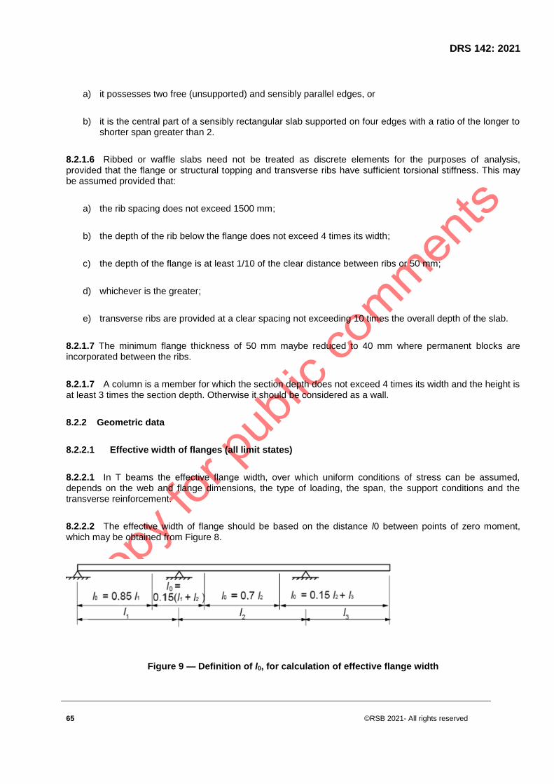
DRS 142: 2021
65 ©RSB 2021- All rights reserved
a) it possesses two free (unsupported) and sensibly parallel edges, or
b) it is the central part of a sensibly rectangular slab supported on four edges with a ratio of the longer to shorter span greater than 2.
8.2.1.6 Ribbed or waffle slabs need not be treated as discrete elements for the purposes of analysis, provided that the flange or structural topping and transverse ribs have sufficient torsional stiffness. This may be assumed provided that:
a) the rib spacing does not exceed 1500 mm;
b) the depth of the rib below the flange does not exceed 4 times its width;
c) the depth of the flange is at least 1/10 of the clear distance between ribs or 50 mm;
d) whichever is the greater;
e) transverse ribs are provided at a clear spacing not exceeding 10 times the overall depth of the slab.
8.2.1.7 The minimum flange thickness of 50 mm maybe reduced to 40 mm where permanent blocks are incorporated between the ribs.
8.2.1.7 A column is a member for which the section depth does not exceed 4 times its width and the height is at least 3 times the section depth. Otherwise it should be considered as a wall.
8.2.2 Geometric data
8.2.2.1 Effective width of flanges (all limit states)
8.2.2.1 In T beams the effective flange width, over which uniform conditions of stress can be assumed, depends on the web and flange dimensions, the type of loading, the span, the support conditions and the transverse reinforcement.
8.2.2.2 The effective width of flange should be based on the distance l0 between points of zero moment, which may be obtained from Figure 8.
Figure 9 — Definition of l0, for calculation of effective flange width

©RSB 2021 - All rights reserved 66
NOTE The length of the cantilever, l3, should be less than half the adjacent span and the ratio of adjacent spans
should lie between 2/3 and 1.5.
8.2.2.3 The effective flange width beff for a T beam or L beam may be derived as:
beff =Σbeff,i +bw ≤ b (8.1)
where
beff,i =0.2bi +0.1l0 ≤ 0.2l0 (8.1a)
and
beff,i ≤ bi (8.1b)
Note for the notations refer to the Figures 9 and 10
Figure 10 — Effective flange width parameters
8.2.2.4 For structural analysis, where a great accuracy is not required, a constant width may be assumed
over the whole span. The value applicable to the span section should be adopted.
8.2.2.2 Effective span of beams and slabs in buildings
NOTE The following provisions are provided mainly for member analysis. For frame analysis some of these
simplifications may be used where appropriate.
8.2.2.2.1 The effective span, leff, of a member should be calculated as follows:
leff = ln + a1 + a2 (8.2)
where:
ln is the clear distance between the faces of the supports;

DRS 142: 2021
67 ©RSB 2021- All rights reserved
values for a1 and a2 , at each end of the span, may be determined from the appropriate ai values in Figure 11 where t is the width of the supporting element as shown.
(a) Non-continuous members (b) Continuous members
(c) Supports considered fully restrained (d) Bearing provided
(e) Cantilever
Figure 11 — Effective span (leff ) for different support conditions
8.2.2.2.2 Continuous slabs and beams may generally be analysed on the assumption that the supports provide no rotational restraint.
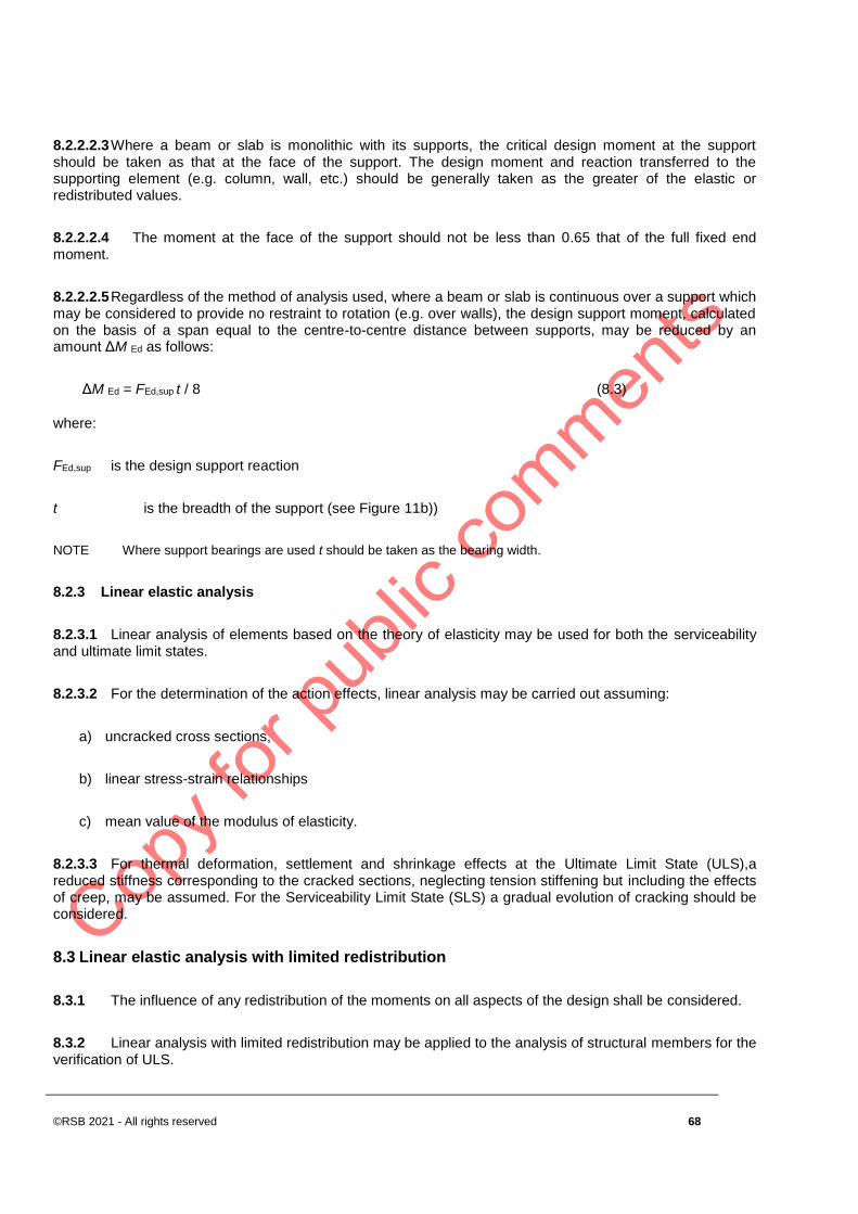
©RSB 2021 - All rights reserved 68
8.2.2.2.3 Where a beam or slab is monolithic with its supports, the critical design moment at the support should be taken as that at the face of the support. The design moment and reaction transferred to the supporting element (e.g. column, wall, etc.) should be generally taken as the greater of the elastic or redistributed values.
8.2.2.2.4 The moment at the face of the support should not be less than 0.65 that of the full fixed end moment.
8.2.2.2.5 Regardless of the method of analysis used, where a beam or slab is continuous over a support which may be considered to provide no restraint to rotation (e.g. over walls), the design support moment, calculated on the basis of a span equal to the centre-to-centre distance between supports, may be reduced by an amount ΔM Ed as follows:
ΔM Ed = FEd,sup t / 8 (8.3)
where:
FEd,sup is the design support reaction
t is the breadth of the support (see Figure 11b))
NOTE Where support bearings are used t should be taken as the bearing width.
8.2.3 Linear elastic analysis
8.2.3.1 Linear analysis of elements based on the theory of elasticity may be used for both the serviceability and ultimate limit states.
8.2.3.2 For the determination of the action effects, linear analysis may be carried out assuming:
a) uncracked cross sections,
b) linear stress-strain relationships
c) mean value of the modulus of elasticity.
8.2.3.3 For thermal deformation, settlement and shrinkage effects at the Ultimate Limit State (ULS),a reduced stiffness corresponding to the cracked sections, neglecting tension stiffening but including the effects of creep, may be assumed. For the Serviceability Limit State (SLS) a gradual evolution of cracking should be considered.
8.3 Linear elastic analysis with limited redistribution
8.3.1 The influence of any redistribution of the moments on all aspects of the design shall be considered.
8.3.2 Linear analysis with limited redistribution may be applied to the analysis of structural members for the verification of ULS.

DRS 142: 2021
69 ©RSB 2021- All rights reserved
8.3.3 The moments at ULS calculated using a linear elastic analysis may be redistributed, provided that the resulting distribution of moments remains in equilibrium with the applied loads.
8.3.4 In continuous beams or slabs which:
a) are predominantly subject to flexure and
b) have the ratio of the lengths of adjacent spans in the range of 0,5 to 2, redistribution of bending moments may be carried out without explicit check on the rotation capacity, provided that:
δ ≥ k1 + k2xu /d for fck ≤ 50 MPa (8.10a)
δ ≥ k3 + k4xu /d for fck > 50 MPa (8.10b)
≥ k5 where Class B and Class C reinforcement is used (see Annex A)
≥ k6 where Class A reinforcement is used (see Annex A)
Where:
ᵟ is the ratio of the redistributed moment to the elastic bending moment
Xu is the depth of the neutral axis at the ultimate limit state after redistribution
D is the effective depth of the section
NOTE The recommended value for k1 is 0.44, for k2 is 1.25(0.6+0.0014/εcu2), for k3 = 0.54, for k4 =
1.25(0.6+0.0014/εcu2), for k5 = 0.7 and k6 = 0.8. εcu2 is the ultimate strain according to Table 2.
8.3.5 Redistribution should not be carried out in circumstances where the rotation capacity cannot be defined with confidence (e.g. in the corners of prestressed frames).
8.3.6 For the design of columns the elastic moments from frame action should be used without any redistribution.
8.4 Plastic analysis
8.4.1 General
8.4.1.1 Methods based on plastic analysis shall only be used for the check at ULS.
8.4.1.2 The ductility of the critical sections shall be sufficient for the envisaged mechanism to be formed.
8.4.1.3 The plastic analysis should be based either on the lower bound (static) method or on the upper bound (kinematic) method.

©RSB 2021 - All rights reserved 70
8.4.1.4 The effects of previous applications of loading may generally be ignored, and a monotonic increase of the intensity of actions may be assumed.
8.4.2 Plastic analysis for beams, frames and slabs
8.4.2.1 Plastic analysis without any direct check of rotation capacity may be used for the ultimate limit state if the conditions of 8.4.1.2 are met.
8.4.2.2 The required ductility may be deemed to be satisfied without explicit verification if all the following are fulfilled:
a) the area of tensile reinforcement is limited such that, at any section
xu/d ≤ 0.25 for concrete strength classes ≤ C50/60
xu/d ≤ 0.15 for concrete strength classes ≥ C55/67
b) reinforcing steel is either Class B or C
c) the ratio of the moments at intermediate supports to the moments in the span should be between 0.5 and 2.
8.4.2.3 Columns should be checked for the maximum plastic moments which can be transmitted by connecting members. For connections to flat slabs this moment should be included in the punching shear calculation.
8.4.2.4 When plastic analysis of slabs is carried out account should be taken of any non-uniform reinforcement, corner tie down forces, and torsion at free edges.
8.4.2.5 Plastic methods may be extended to non-solid slabs (ribbed, hollow, waffle slabs) if their response is similar to that of a solid slab, particularly with regard to the torsional effects.
Figure 12 — Plastic rotation θs of reinforced concrete sections for continuous beams and continuous one way spanning slabs.
8.4.2.6 In region of yield hinges, x /d should not exceed the value 0.45 for concrete strength classes less than or equal to C50/60, and 0.35 for concrete strength classes greater than or equal to C55/67.
8.4.2.7 The rotation θ s should be determined on the basis of the design values for actions and materials and on the basis of mean values for prestressing at the relevant time.

DRS 142: 2021
71 ©RSB 2021- All rights reserved
8.4.2.8 In the simplified procedure, the allowable plastic rotation may be determined by multiplying the basic value of allowable rotation, θpl,d, by a correction factor kλ that depends on the shear slenderness.
NOTE The recommended values of θ pl,d for steel Classes B and C (the use of Class A steel is not recommended for
plastic analysis) and concrete strength classes less than or equal to C50/60 and C90/105 are given in Figure 13.
8.4.2.9 The values for concrete strength classes C 55/67 to C 90/105 may be interpolated accordingly. The values apply for a shear slenderness λ = 3.0. For different values of shear slenderness θ pl,d should be multiplied by kλ:
k λ = (8.11)
Where λ is the ratio of the distance between point of zero and maximum moment after redistribution and effective depth, d.
As a simplification λ may be calculated for the concordant design values of the bending moment and shear :
λ = MSd / (VSd ⋅ d) (8.12)
Figure 13 — Basic value of allowable rotation, θ pl,d, of reinforced concrete sections for Class B and C reinforcement. The values apply for a shear slenderness λ = 3.0
8.5 Non-linear analysis
8.5.1 Non-linear methods of analysis may be used for both ULS and SLS, provided that equilibrium and compatibility are satisfied and an adequate non-linear behaviour for materials is assumed. The analysis may be first or second order.
8.5.2 At the ultimate limit state, the ability of local critical sections to withstand any inelastic deformations implied by the analysis should be checked, taking appropriate account of uncertainties.

©RSB 2021 - All rights reserved 72
8.5.3 For structures predominantly subjected to static loads, the effects of previous applications of loading may generally be ignored, and a monotonic increase of the intensity of the actions may be assumed.
8.5.4 The use of material characteristics which represent the stiffness in a realistic way but take account of the uncertainties of failure shall be used when using non-linear analysis. Only those design formats which are valid within the relevant fields of application shall be used.
8.5.5 For slender structures, in which second order effects cannot be ignored, the design method given in 5.8.6 may be used.
8.6 Analysis of second order effects with axial load
8.6.1 General
8.6.1.1 This clause deals with members and structures in which the structural behaviour is significantly influenced by second order effects (e.g. columns, walls, piles, arches and shells).
NOTE Global second order effects are likely to occur in structures with a flexible bracing system.
8.6.1.2 Where second order effects are taken into account, equilibrium and resistance shall be verified in the deformed state. Deformations shall be calculated taking into account the relevant effects of cracking, non-linear material properties and creep.
NOTE In an analysis assuming linear material properties, this can be taken into account by means of reduced
stiffness values, see 8.6.8.
8.6.1.3 Where relevant, analysis shall include the effect of flexibility of adjacent members and foundations (soil-structure interaction).
8.6.1.4 The structural behaviour shall be considered in the direction in which deformations can occur, and biaxial bending shall be taken into account when necessary.
8.6.1.5 Uncertainties in geometry and position of axial loads shall be taken into account as additional first order effects based on geometric imperfections.
8.6.1.6 Second order effects may be ignored if they are less than 10 % of the corresponding first order effects. Simplified criteria are given for isolated members in 8.6.2.1and for structures in 8.6.2.3.
8.6.2 Simplified criteria for second order effects
8.6.2.1 Slenderness criterion for isolated members
8.6.2.1.1 As an alternative to 8.6.1, second order effects may be ignored if the slenderness λ is below a certain value λlim.
NOTE The recommended value of λlim follows from:

DRS 142: 2021
73 ©RSB 2021- All rights reserved
λlim = 20⋅A⋅B⋅C/ (8.13)
where:
A is 1 / (1+0.2φef) (if φef is not known, A = 0.7 may be used)
B is 1+ 2ω (if ω is not known, B = 1.1 may be used)
C is 1.7 - rm (if rm is not known, C = 0.7 may be used)
φef is effective creep ratio;ω Asfyd / (Acfcd); mechanical reinforcement ratio;
As is the total area of longitudinal reinforcement
n NEd / (Acfcd); relative normal force
rm M01/M02; moment ratio
M01, M02 are the first order end moments,
If the end moments M01 and M02 give tension on the same side, rm should be taken positive (i.e. C ≤ 1.7), otherwise
negative (i.e. C > 1.7).
In the following cases, rm should be taken as 1.0 (i.e. C = 0.7):
a) for braced members in which the first order moments arise only from or predominantly due to imperfections or
transverse loading;
b) for unbraced members in general.
8.6.2.1.2 In cases with biaxial bending, the slenderness criterion may be checked separately for each direction. Depending on the outcome of this check, second order effects (a) may be ignored in both directions, (b) should be taken into account in one direction, or (c) should be taken into account in both directions.
8.6.3 Slenderness and effective length of isolated members
8.6.3.1 The slenderness ratio is defined as follows:
λ = l0 / i (8.14)
where:
l0 is the effective length

©RSB 2021 - All rights reserved 74
I is the radius of gyration of the uncracked concrete section
8.6.3.2 For a general definition of the effective length, see examples of effective length for isolated members with constant cross section are given in Figure 14.
a) l0 = l b) l0 = 2l c) l0 = 0,7l d) l0 = l / 2 e) l0 = l f) l /2 <l0< l g) l0 > 2l
Figure 14 — Examples of different buckling modes and corresponding effective lengths for isolated members
8.6.3.3 For compression members in regular frames, the slenderness criterion should be checked with an effective length l0 determined in the following way:
(8.15)
Unbraced members (see Figure 5.7 (g)):
(8.16)
where:
k1, k2 are the relative flexibilities of rotational restraints at ends 1 and 2 respectively:
k = (θ / M)⋅ (EΙ / l)
θ is the rotation of restraining members for bending moment M; see also Figure 14 (f) and (g)
EΙ is the bending stiffness of compression member,

DRS 142: 2021
75 ©RSB 2021- All rights reserved
L is the clear height of compression member between end restraints
NOTE k = 0 is the theoretical limit for rigid rotational restraint, and k = ∞ represents the limit for no restraint at all.
Since fully rigid restraint is rare in practice, a minimum value of 0,1 is recommended for k1 and k2.
8.6.3.4 If an adjacent compression member (column) in a node is likely to contribute to the rotation at buckling, then (EΙ / l ) in the definition of k should be replaced by [(EΙ / l )a+(EΙ / l )b], a and b representing the compression member (column) above and below the node.
8.6.3.5 In the definition of effective lengths, the stiffness of restraining members should include the effect of cracking, unless they can be shown to be uncracked in ULS.
8.6.3.6 For other cases than those in (2) and (3), e.g. members with varying normal force and/or cross section, the criterion in 8.6.2.1 should be checked with an effective length based on the buckling load (calculated e.g. by a numerical method):
(8.17)
where:
EI is a representative bending stiffness
NB is buckling load expressed in terms of this EI
(in Expression (8.14), i should also correspond to this EI)
8.6.4 Global second order effects in buildings
8.6.4.1 As an alternative to 5.8.2 (6), global second order effects in buildings may be ignored if
( 8.18)
where:
FV,Ed is the total vertical load (on braced and bracing members)
ns is the number of storeys
L is the total height of building above level of moment restraint
Ecd is the design value of the modulus of elasticity of concrete,
Ic is the second moment of area (uncracked concrete section) of bracing member(s)
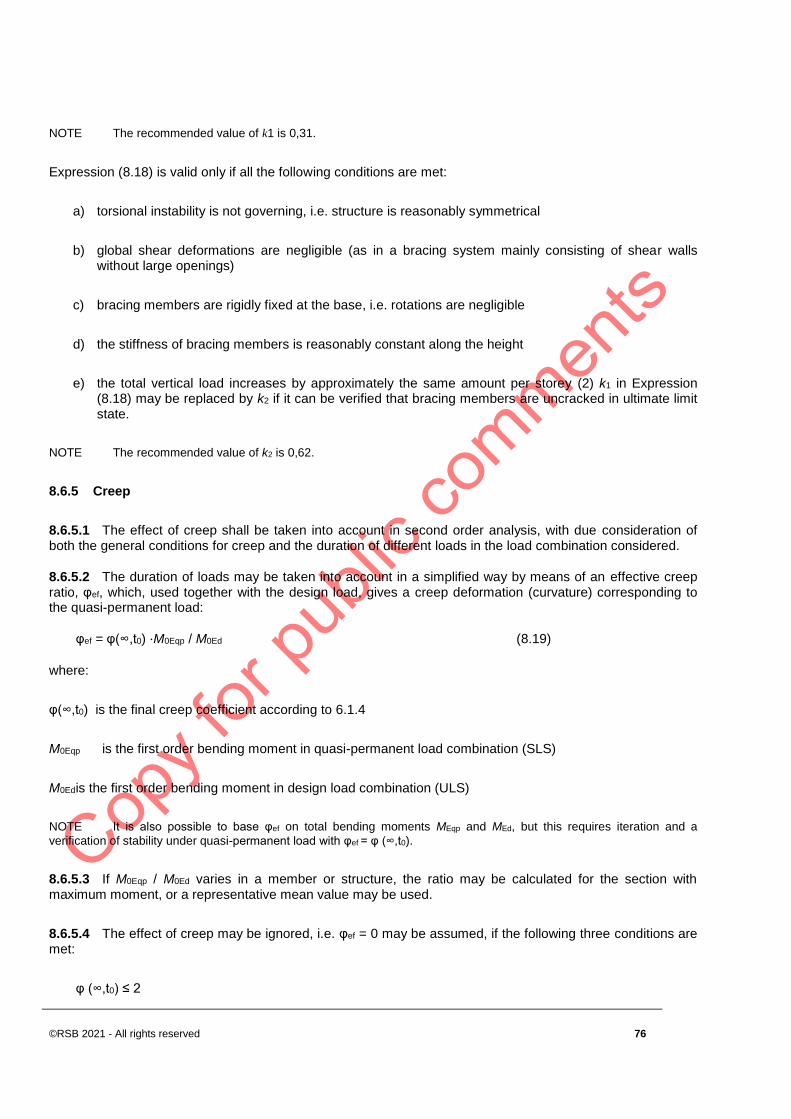
©RSB 2021 - All rights reserved 76
NOTE The recommended value of k1 is 0,31.
Expression (8.18) is valid only if all the following conditions are met:
a) torsional instability is not governing, i.e. structure is reasonably symmetrical
b) global shear deformations are negligible (as in a bracing system mainly consisting of shear walls without large openings)
c) bracing members are rigidly fixed at the base, i.e. rotations are negligible
d) the stiffness of bracing members is reasonably constant along the height
e) the total vertical load increases by approximately the same amount per storey (2) k1 in Expression (8.18) may be replaced by k2 if it can be verified that bracing members are uncracked in ultimate limit state.
NOTE The recommended value of k2 is 0,62.
8.6.5 Creep
8.6.5.1 The effect of creep shall be taken into account in second order analysis, with due consideration of both the general conditions for creep and the duration of different loads in the load combination considered.
8.6.5.2 The duration of loads may be taken into account in a simplified way by means of an effective creep ratio, φef, which, used together with the design load, gives a creep deformation (curvature) corresponding to the quasi-permanent load:
φef = φ(∞,t0) ⋅M0Eqp / M0Ed (8.19)
where:
φ(∞,t0) is the final creep coefficient according to 6.1.4
M0Eqp is the first order bending moment in quasi-permanent load combination (SLS)
M0Ed is the first order bending moment in design load combination (ULS)
NOTE It is also possible to base φef on total bending moments MEqp and MEd, but this requires iteration and a
verification of stability under quasi-permanent load with φef = φ (∞,t0).
8.6.5.3 If M0Eqp / M0Ed varies in a member or structure, the ratio may be calculated for the section with maximum moment, or a representative mean value may be used.
8.6.5.4 The effect of creep may be ignored, i.e. φef = 0 may be assumed, if the following three conditions are met:
φ (∞,t0) ≤ 2

DRS 142: 2021
77 ©RSB 2021- All rights reserved
λ ≤ 75
M0Ed/NEd ≥ h
Here M0Ed is the first order moment and h is the cross section depth in the corresponding direction.
NOTE If the conditions for neglecting second order effects according to 8.7.1.6 or 8.7.2.3 are only just achieved, it
may be too unconservative to neglect both second order effects and creep, unless the mechanical reinforcement ratio (ω,
see 8.6.2.1) is at least 0,25.
8.6.6 Methods of analysis
8.6.6.1 The methods of analysis include a general method, based on non-linear second order analysis, see 8.6.7 and the following two simplified methods:
a) Method based on nominal stiffness, see 8.6.8
b) Method based on nominal curvature, see 8.6.7
NOTE Nominal second order moments provided by the simplified methods (a) and (b) are sometimes greater than
those corresponding to instability. This is to ensure that the total moment is compatible with the cross section resistance.
8.6.6.2 Method (a) may be used for both isolated members and whole structures, if nominal stiffness values are estimated appropriately; see 8.6.8.
8.6.6.3 Method (b) is mainly suitable for isolated members; see 5.8.8. However, with realistic assumptions concerning the distribution of curvature, the method in 8.6.7 can also be used for structures.
8.6.7 General method
8.6.7.1 The general method is based on non-linear analysis, including geometric non-linearity i.e. second order effects. The general rules for non-linear analysis given in 8.5 apply.
8.6.7.2 Stress-strain curves for concrete and steel suitable for overall analysis shall be used. The effect of creep shall be taken into account.
8.6.7.3 With stress-strain diagrams based on design values, a design value of the ultimate load is obtained directly from the analysis. In Expression (6.14), and in the k value, fcm is then substituted by the design compressive strength fcd and Ecm is substituted by
Ecd = Ecm / CE (8.20)
NOTE The value recommended value of γCE is 1,2.
8.6.7.4 In the absence of more refined models, creep may be taken into account by multiplying all strain values in the concrete stress-strain diagram according to 8.6.7.3 with a factor (1 + φef), where φef is the effective creep ratio according to 8.6.5.
8.6.7.5 The favourable effect of tension stiffening may be taken into account.

©RSB 2021 - All rights reserved 78
NOTE This effect is favourable, and may always be ignored, for simplicity.
8.6.7.6 Normally, conditions of equilibrium and strain compatibility are satisfied in a number of cross sections. A simplified alternative is to consider only the critical cross section(s), and to assume a relevant variation of the curvature in between, e.g. similar to the first order moment or simplified in another appropriate way.
8.6.8 Method based on nominal stiffness
8.6.8.1 General
8.6.8.2 In a second order analysis based on stiffness, nominal values of the flexural stiffness should be used, taking into account the effects of cracking, material non-linearity and creep on the overall behaviour. This also applies to adjacent members involved in the analysis, e.g. beams, slabs or foundations. Where relevant, soil-structure interaction should be taken into account.
8.6.8.3 The resulting design moment is used for the design of cross sections with respect to bending moment and axial force according to 9.1, as compared with 8.6.6.1.
8.6.8.2 Nominal stiffness
8.6.8.2.1 The following model may be used to estimate the nominal stiffness of slender compression members with arbitrary cross section:
EI = KcEcdIc + KsEsIs (8.21)
where:
Ecd is the design value of the modulus of elasticity of concrete, see 8.6.7.3
Ic is the moment of inertia of concrete cross section
Es is the design value of the modulus of elasticity of reinforcement, 8.6.7.3
Is is the second moment of area of reinforcement, about the centre of area of the concrete
Kc is a factor for effects of cracking, creep etc, see 8.6.8.2.2 or 8.6.8.2.3
Ks is a factor for contribution of reinforcement, see 8.6.8.2.2 or 8.6.8.2.3
8.6.8.2.2 The following factors may be used in Expression (8.21), provided ρ ≥ 0,002: Ks = 1
Kc = k1k2 / (1 + φef) (8.22)
where:
ρ is the geometric reinforcement ratio, As/Ac

DRS 142: 2021
79 ©RSB 2021- All rights reserved
As is the total area of reinforcement
Ac is the area of concrete section
φef is the effective creep ratio, see 8.6.5
k1 is a factor which depends on concrete strength class, Expression (8.23)
k2 is a factor which depends on axial force and slenderness, Expression (8.24)
(8.23)
(8.24)
where:
n is the relative axial force, NEd / (Acfcd)
λ is the slenderness ratio, see 8.6.4
If the slenderness ratio λ is not defined, k2 may be taken as
k2 = n⋅0.30 ≤ 0.20 (8.25)
8.6.8.2.2 As a simplified alternative, provided ρ ≥ 0,01, the following factors may be used in Expression (8.21):
Ks = 0
Kc = 0.3 / (1 + 0.5φef) (8.26)
NOTE The simplified alternative may be suitable as a preliminary step, followed by a more accurate calculation
according to (8.6.7.2.2).
8.6.8.2.3 In statically indeterminate structures, unfavourable effects of cracking in adjacent members should be taken into account. Expressions (8.21-8.26) are not generally applicable to such members. However, as a simplification, fully cracked sections may be assumed. The stiffness should be based on an effective concrete modulus:
Ecd,eff = Ecd /(1+φef) (8.27)
where:
Ecd is the design value of the modulus of elasticity according to 8.6.7.3
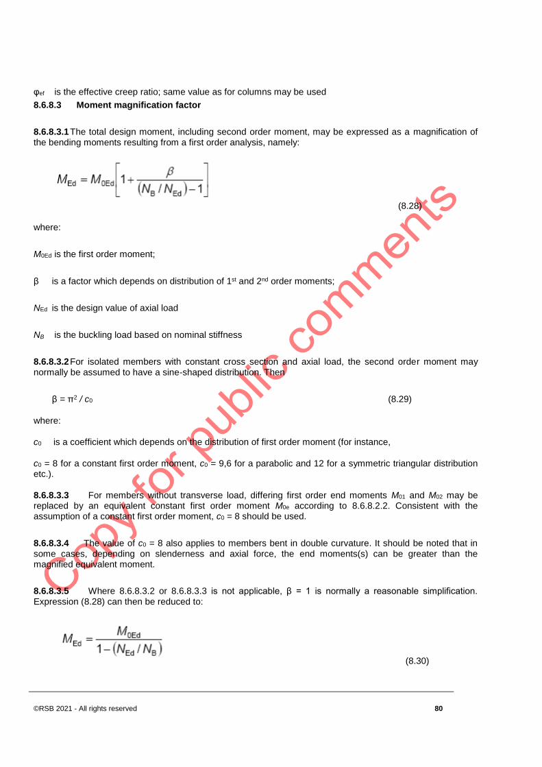
©RSB 2021 - All rights reserved 80
φef is the effective creep ratio; same value as for columns may be used
8.6.8.3 Moment magnification factor
8.6.8.3.1 The total design moment, including second order moment, may be expressed as a magnification of the bending moments resulting from a first order analysis, namely:
(8.28)
where:
M0Ed is the first order moment;
β is a factor which depends on distribution of 1st and 2nd order moments;
NEd is the design value of axial load
NB is the buckling load based on nominal stiffness
8.6.8.3.2 For isolated members with constant cross section and axial load, the second order moment may normally be assumed to have a sine-shaped distribution. Then
β = π2 / c0 (8.29)
where:
c0 is a coefficient which depends on the distribution of first order moment (for instance,
c0 = 8 for a constant first order moment, c0 = 9,6 for a parabolic and 12 for a symmetric triangular distribution etc.).
8.6.8.3.3 For members without transverse load, differing first order end moments M01 and M02 may be replaced by an equivalent constant first order moment M0e according to 8.6.8.2.2. Consistent with the assumption of a constant first order moment, c0 = 8 should be used.
8.6.8.3.4 The value of c0 = 8 also applies to members bent in double curvature. It should be noted that in some cases, depending on slenderness and axial force, the end moments(s) can be greater than the magnified equivalent moment.
8.6.8.3.5 Where 8.6.8.3.2 or 8.6.8.3.3 is not applicable, β = 1 is normally a reasonable simplification. Expression (8.28) can then be reduced to:
(8.30)

DRS 142: 2021
81 ©RSB 2021- All rights reserved
NOTE 8.6.8.3.4 is also applicable to the global analysis of certain types of structures, e.g. structures braced by shear
walls and similar, where the principal action effect is bending moment in bracing units.
8.6.9 Analysis for some particular structural members
8.6.9.1 Slabs supported on columns are defined as flat slabs.
8.6.9.2 Shear walls are plain or reinforced concrete walls that contribute to lateral stability of the structure.
8.6.10 Lateral instability of slender beams
8.6.10.1 Lateral instability of slender beams shall be taken into account where necessary, e.g. for precast beams during transport and erection, for beams without sufficient lateral bracing in the finished structure etc. Geometric imperfections shall be taken into account.
8.6.10.2 A lateral deflection of l/300 should be assumed as a geometric imperfection in the verification of
beams in unbraced conditions, with l= total length of beam. In finished structures, bracing from connected members may be taken into account
8.6.10.3 Second order effects in connection with lateral instability may be ignored if the following conditions are fulfilled:
persistent situations: and ()
transient situations: : and ()
where
is the distance between torsional restraints
h is the total depth of beam in central part of
b is the width of compression flange
8.6.10.4 Torsion associated with lateral instability should be taken into account in the design of supporting structures.
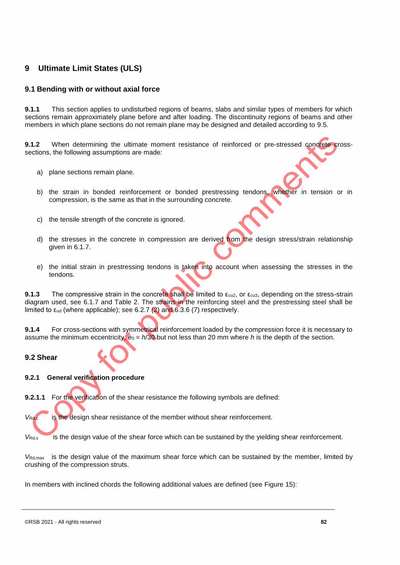
©RSB 2021 - All rights reserved 82
9 Ultimate Limit States (ULS)
9.1 Bending with or without axial force
9.1.1 This section applies to undisturbed regions of beams, slabs and similar types of members for which sections remain approximately plane before and after loading. The discontinuity regions of beams and other members in which plane sections do not remain plane may be designed and detailed according to 9.5.
9.1.2 When determining the ultimate moment resistance of reinforced or pre-stressed concrete cross-sections, the following assumptions are made:
a) plane sections remain plane.
b) the strain in bonded reinforcement or bonded prestressing tendons, whether in tension or in compression, is the same as that in the surrounding concrete.
c) the tensile strength of the concrete is ignored.
d) the stresses in the concrete in compression are derived from the design stress/strain relationship given in 6.1.7.
e) the initial strain in prestressing tendons is taken into account when assessing the stresses in the tendons.
9.1.3 The compressive strain in the concrete shall be limited to εcu2, or εcu3, depending on the stress-strain diagram used, see 6.1.7 and Table 2. The strains in the reinforcing steel and the prestressing steel shall be limited to εud (where applicable); see 6.2.7 (2) and 6.3.6 (7) respectively.
9.1.4 For cross-sections with symmetrical reinforcement loaded by the compression force it is necessary to assume the minimum eccentricity, e0 = h/30 but not less than 20 mm where h is the depth of the section.
9.2 Shear
9.2.1 General verification procedure
9.2.1.1 For the verification of the shear resistance the following symbols are defined:
VRd,c is the design shear resistance of the member without shear reinforcement.
VRd,s is the design value of the shear force which can be sustained by the yielding shear reinforcement.
VRd,max is the design value of the maximum shear force which can be sustained by the member, limited by crushing of the compression struts.
In members with inclined chords the following additional values are defined (see Figure 15):
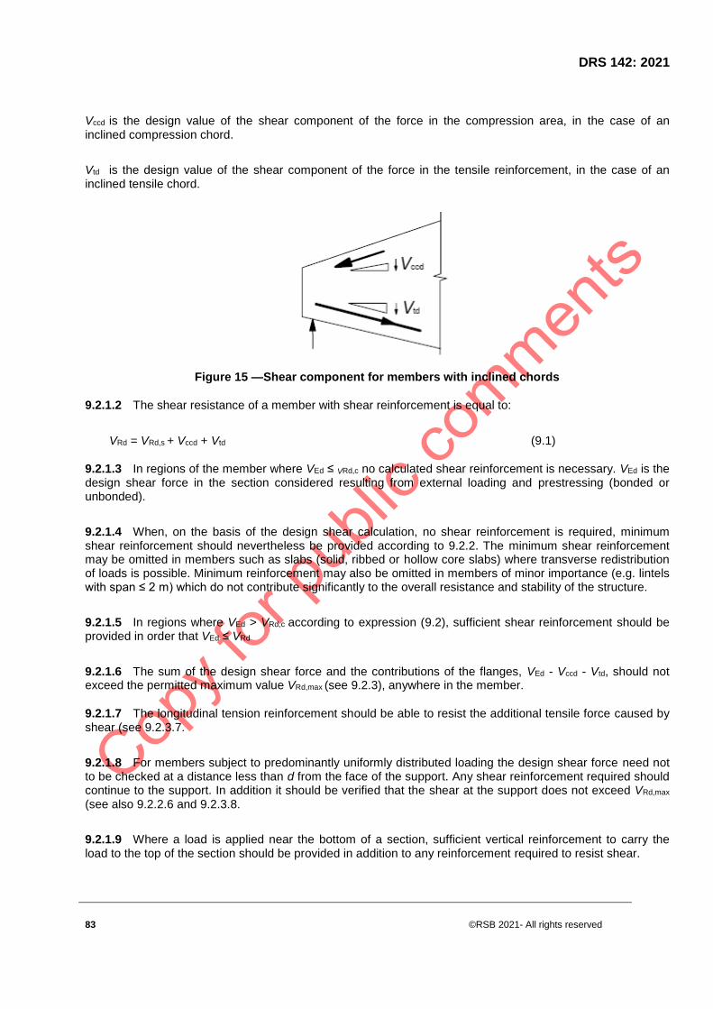
DRS 142: 2021
83 ©RSB 2021- All rights reserved
Vccd is the design value of the shear component of the force in the compression area, in the case of an inclined compression chord.
Vtd is the design value of the shear component of the force in the tensile reinforcement, in the case of an inclined tensile chord.
Figure 15 —Shear component for members with inclined chords
9.2.1.2 The shear resistance of a member with shear reinforcement is equal to:
VRd = VRd,s + Vccd + Vtd (9.1)
9.2.1.3 In regions of the member where VEd ≤ VRd,c no calculated shear reinforcement is necessary. VEd is the design shear force in the section considered resulting from external loading and prestressing (bonded or unbonded).
9.2.1.4 When, on the basis of the design shear calculation, no shear reinforcement is required, minimum shear reinforcement should nevertheless be provided according to 9.2.2. The minimum shear reinforcement may be omitted in members such as slabs (solid, ribbed or hollow core slabs) where transverse redistribution of loads is possible. Minimum reinforcement may also be omitted in members of minor importance (e.g. lintels with span ≤ 2 m) which do not contribute significantly to the overall resistance and stability of the structure.
9.2.1.5 In regions where VEd > VRd,c according to expression (9.2), sufficient shear reinforcement should be provided in order that VEd ≤ VRd
9.2.1.6 The sum of the design shear force and the contributions of the flanges, VEd - Vccd - Vtd, should not exceed the permitted maximum value VRd,max (see 9.2.3), anywhere in the member.
9.2.1.7 The longitudinal tension reinforcement should be able to resist the additional tensile force caused by shear (see 9.2.3.7.
9.2.1.8 For members subject to predominantly uniformly distributed loading the design shear force need not to be checked at a distance less than d from the face of the support. Any shear reinforcement required should continue to the support. In addition it should be verified that the shear at the support does not exceed VRd,max
(see also 9.2.2.6 and 9.2.3.8.
9.2.1.9 Where a load is applied near the bottom of a section, sufficient vertical reinforcement to carry the load to the top of the section should be provided in addition to any reinforcement required to resist shear.

©RSB 2021 - All rights reserved 84
9.2.2 Members not requiring design shear reinforcement
9.2.2.1 The design value for the shear resistance VRd,c is given by:
VRd,c = [CRd,ck(100 ρ l fck)1/3 + k1 σcp] bwd (9.2.a)
with a minimum of
VRd,c = (vmin + k1σcp) bwd (9.2.b)
where:
fck is in MPa
Asl is the area of the tensile reinforcement, which extends ≥ (lbd + d) beyond the section considered (see
Figure 15). (see Expression (9.1))
bw is the smallest width of the cross-section in the tensile area [mm]
σcp = NEd/Ac < 0.2 fcd [MPa]
NEd is the axial force in the cross-section due to loading or prestressing [in N] (NEd>0 for compression). The influence of imposed deformations on may be ignored.
AC is the area of concrete cross section [mm2]
VRd,c is [N]
NOTE The recommended value for CRd,c is 0.18/ γc, that for vmin is given by Expression (9.3) and that for k1 is 0.15.
vmin =0.035 k3/2 ⋅ fck1/2 (9.3)
Figure 16 — Definition of Asl in Expression (9.2)

DRS 142: 2021
85 ©RSB 2021- All rights reserved
9.2.2.2 The regions cracked in bending may be calculated using expression (9.2a). In regions uncracked in bending (where the flexural tensile stress is smaller than fctk,0.05/γc) the shear resistance should be limited by the tensile strength of the concrete. In these regions the shear resistance is given by:
(9.4)
where
Ι is the second moment of area
bw is the width of the cross-section at the centroidal axis, allowing for the presence of ducts in accordance with Expressions (9.16) and (9.17)
S is the first moment of area above and about the centroidal axis
αI = lx/lpt2 ≤ 1.0 for pretensioned tendons
= 1.0 for other types of prestressing
lx is the distance of section considered from the starting point of the transmission length
σcp is the concrete compressive stress at the centroidal axis due to axial loading and/or prestressing (σcp = NEd /Ac in MPa, NEd > 0 in compression)
9.2.2.3 For cross-sections where the width varies over the height, the maximum principal stress may occur on an axis other than the centroidal axis. In such a case the minimum value of the shear resistance should be found by calculating VRd,c at various axes in the cross-section.
9.2.2.4 The calculation of the shear resistance according to Expression (9.4) is not required for cross-sections that are nearer to the support than the point which is the intersection of the elastic centroidal axis and a line inclined from the inner edge of the support at an angle of 45o.

©RSB 2021 - All rights reserved 86
(a) Beam with direct support (b) Corbel
Figure 17 — Loads near supports
9.2.3 Members requiring design shear reinforcement
9.2.3.1 The design of members with shear reinforcement is based on a truss model (Figure 18). Limiting values for the angle θ of the inclined struts in the web are given in 9.2.3.2. In Figure 18 the following notations are shown:
Α is the angle between shear reinforcement and the beam axis perpendicular to the shear force (measured positive as shown in Figure 18)
θ is the angle between the concrete compression strut and the beam axis perpendicular to the shear force
Ftd is the design value of the tensile force in the longitudinal reinforcement
Fcd is the design value of the concrete compression force in the direction of the longitudinal member axis.
bw is the minimum width between tension and compression chords
z is the inner lever arm, for a member with constant depth, corresponding to the bending moment in the element under consideration. In the shear analysis of reinforced concrete without axial force, the approximate value z = 0.9d may normally be used.
9.2.3.2 In elements with inclined prestressing tendons, longitudinal reinforcement at the tensile chord θ should be provided to carry the longitudinal tensile force due to shear defined in (10) .‰
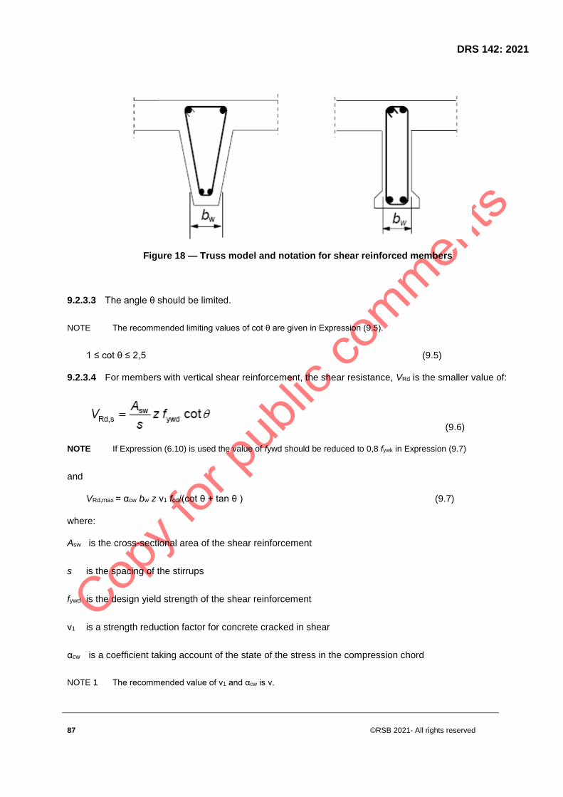
DRS 142: 2021
87 ©RSB 2021- All rights reserved
Figure 18 — Truss model and notation for shear reinforced members
9.2.3.3 The angle θ should be limited.
NOTE The recommended limiting values of cot θ are given in Expression (9.5).
1 ≤ cot θ ≤ 2,5 (9.5)
9.2.3.4 For members with vertical shear reinforcement, the shear resistance, VRd is the smaller value of:
(9.6)
NOTE If Expression (6.10) is used the value of fywd should be reduced to 0,8 fywk in Expression (9.7)
and
VRd,max = αcw bw z ν1 fcd/(cot θ + tan θ ) (9.7)
where:
Asw is the cross-sectional area of the shear reinforcement
s is the spacing of the stirrups
fywd is the design yield strength of the shear reinforcement
ν1 is a strength reduction factor for concrete cracked in shear
αcw is a coefficient taking account of the state of the stress in the compression chord
NOTE 1 The recommended value of ν1 and αcw is ν.

©RSB 2021 - All rights reserved 88
NOTE 2 If the design stress of the shear reinforcement is below 80 % of the characteristic yield stress fyk, ν1 may be
taken as:
ν1 = 0.6 for fck ≤ 60 MPa
ν1 = 0.9 – fck /200 > 0.5 for fck ≥ 60 MPa
NOTE The recommended value of αcw is as follows:
1 for non-prestressed structures
(1 + σcp/fcd) for 0 < σcp ≤ 0.25 fcd (9.8.a)
1.25 for 0.25 fcd < σcp ≤ 0.5 fcd ( 9.8.b)
2.5 (1 - σcp/fcd) for 0.5 fcd < σcp < 1.0 fcd (9.11)
where:
σ cp is the mean compressive stress, measured positive, in the concrete due to the design axial force. This should be obtained by averaging it over the concrete section taking account of the reinforcement. The value of σcp need not be calculated at a distance less than 0.5d cot θ from the edge of the support.
NOTE 3 The maximum effective cross-sectional area of the shear reinforcement, Asw,max, for cot θ =1 is given by:
(9.12)
9.2.3.5 For members with inclined shear reinforcement, the shear resistance is the smaller value of:
(9.13)
and
(9.14)
NOTE The maximum effective shear reinforcement, Asw,max for cot θ =1 follows from:
(9.15)
9.2.4 Shear between web and flanges
9.2.4.1 A minimum amount of longitudinal reinforcement should be provided, as specified in 9.3.1.
9.2.4.2 The longitudinal shear stress, vEd, at the junction between one side of a flange and the web is determined by the change of the normal (longitudinal) force in the part of the flange considered, according to:

DRS 142: 2021
89 ©RSB 2021- All rights reserved
vEd = ΔFd/(hf ⋅ Δx) (9.16)
where:
hf is the thickness of flange at the junctions
Δx is the length under consideration, see Figure 19
ΔFd is the change of the normal force in the flange over the length Δx.
− compressive struts −longitudinal bar anchored beyond this projected point
Figure 19 — Notations for the connection between flange and web
9.2.4.3 The maximum value that may be assumed for Δx is half the distance between the section where the moment is 0 and the section where the moment is maximum. Where point loads are applied the length Δx should not exceed the distance between point loads.
9.2.4.4 The transverse reinforcement per unit length Asf/sf may be determined as follows:
(9.17)
satisfied:
vEd ≤ ν fcd sin θf cos θf (9.18)
NOTE The recommended values of cot θf in the calculation are in the following range:

©RSB 2021 - All rights reserved 90
1.0 ≤ cot θ f ≤ 2.0 for compression flanges (45° ≥θf ≥ 26.5°)
1.0 ≤ cot θ f ≤ 1.25 for tension flanges (45° ≥ θf ≥ 38.6°)
9.2.4.5 In the case of combined shear between the flange and the web, and transverse bending, the area of steel should be the greater than that given by Expression (9.17) or half that given by Expression (9.17) plus that required for transverse bending.
9.2.4.6 If vEd is less than or equal to kfctd no extra reinforcement above that for flexure is required.
NOTE The recommended value of k is 0.4.
9.2.4.7 Longitudinal tension reinforcement in the flange should be anchored beyond the strut required to transmit the force back to the web at the section where this reinforcement is required (See Section (A - A) of Figure 19).
9.3 Torsion
9.3.1 General
9.3.1.1 Where the static equilibrium of a structure depends on the torsional resistance of elements of the structure, a full torsional design covering both ultimate and serviceability limit states shall be made.
9.3.1.2 Where, in statically indeterminate structures, torsion arises from consideration of compatibility only, and the structure is not dependent on the torsional resistance for its stability, then it will normally be unnecessary to consider torsion at the ultimate limit state. In such cases a minimum reinforcement in the form of stirrups and longitudinal bars should be provided in order to prevent excessive cracking.
9.3.1.3 The torsional resistance of a section may be calculated on the basis of a thin-walled closed section, in which equilibrium is satisfied by a closed shear flow. Solid sections may be modeled by equivalent thin-walled sections. Complex shapes, such as T-sections, may be divided into a series of sub-sections, each of which is modelled as an equivalent thin-walled section, and the total torsional resistance taken as the sum of the capacities of the individual elements.
9.3.1.4 The distribution of the acting torsional moments over the sub-sections should be in proportion to their uncracked torsional stiffnesses. For non-solid sections the equivalent wall thickness should not exceed the actual wall thickness.
9.3.1.5 Each sub-section may be designed separately.
9.3.2 Warping torsion
9.3.1.1 For closed thin-walled sections and solid sections, warping torsion may normally be ignored.
9.3.1.2 In open thin walled members it may be necessary to consider warping torsion. For very slender cross-sections the calculation should be carried out on the basis of a beam-grid model and for other cases on the basis of a truss model. In all cases the design should be carried out according to the design rules for bending and longitudinal normal force, and for shear.
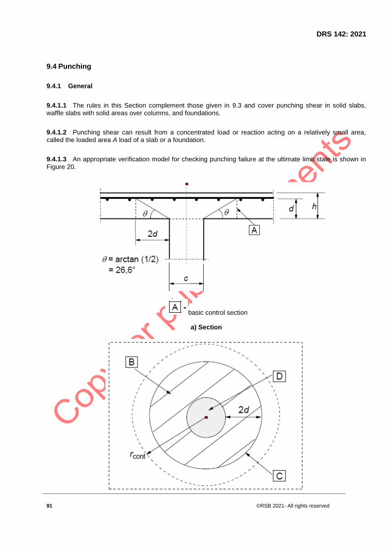
DRS 142: 2021
91 ©RSB 2021- All rights reserved
9.4 Punching
9.4.1 General
9.4.1.1 The rules in this Section complement those given in 9.3 and cover punching shear in solid slabs, waffle slabs with solid areas over columns, and foundations.
9.4.1.2 Punching shear can result from a concentrated load or reaction acting on a relatively small area, called the loaded area A load of a slab or a foundation.
9.4.1.3 An appropriate verification model for checking punching failure at the ultimate limit state is shown in Figure 20.
basic control section
a) Section

©RSB 2021 - All rights reserved 92
b) Plan
Figure 20− Verification model for punching shear at the ultimate limit state
rcont - further control perimeter
9.4.1.4 The shear resistance should be checked at the face of the column and at the basic control perimeter u1. If shear reinforcement is required a further perimeter uout,ef should be found where shear reinforcement is no longer required.
9.4.1.5 The rules given in 9.4 are principally formulated for the case of uniformly distributed loading. In special cases, such as footings, the load within the control perimeter adds to the resistance of the structural system, and may be subtracted when determining the design punching shear stress.
9.4.2 Load distribution and basic control perimeter
9.4.2.1 The basic control perimeter u1 may normally be taken to be at a distance 2,0d from the loaded area and should be constructed so as to minimise its length (see Figure 21). The effective depth of the slab is assumed constant and may normally be taken as:
( 9.19)
where dy and dz are the effective depths of the reinforcement in two orthogonal directions.
Figure 21 — Typical basic control perimeters around loaded areas
9.4.2.2 Control perimeters at a distance less than 2d should be considered where the concentrated force is opposed by a high pressure (e.g. soil pressure on a base), or by the effects of a load or reaction within a distance 2d of the periphery of area of application of the force.
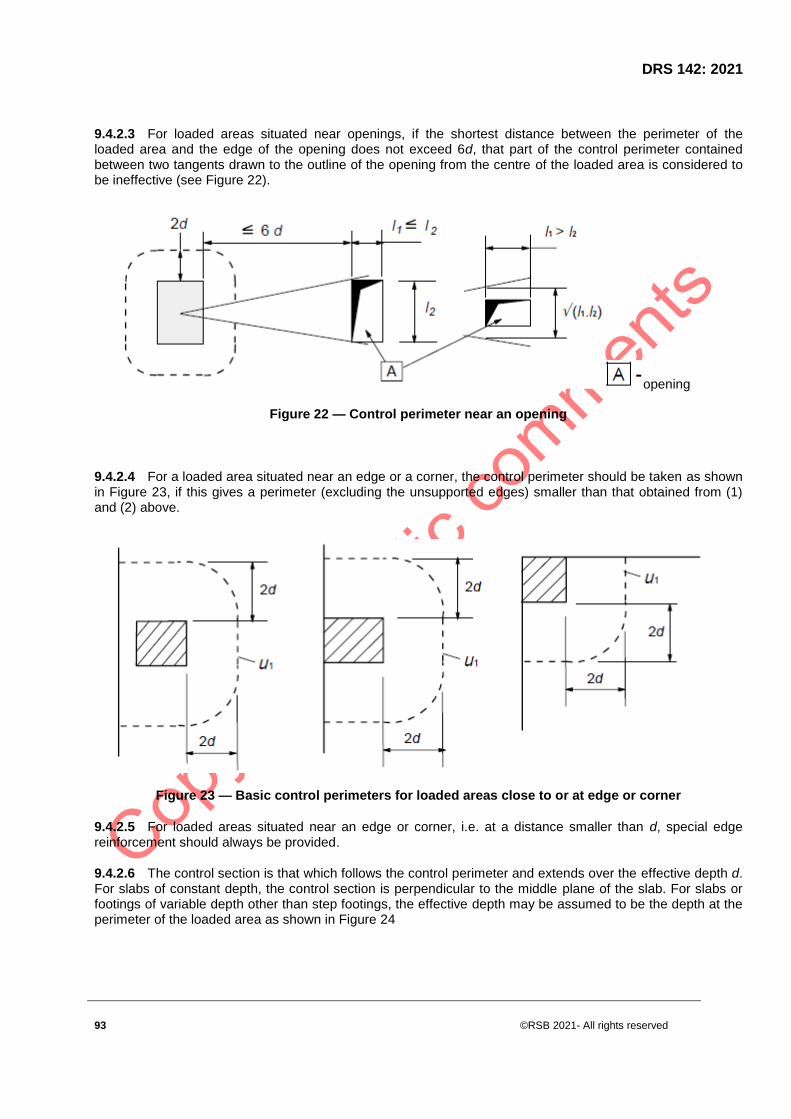
DRS 142: 2021
93 ©RSB 2021- All rights reserved
9.4.2.3 For loaded areas situated near openings, if the shortest distance between the perimeter of the loaded area and the edge of the opening does not exceed 6d, that part of the control perimeter contained between two tangents drawn to the outline of the opening from the centre of the loaded area is considered to be ineffective (see Figure 22).
opening
Figure 22 — Control perimeter near an opening
9.4.2.4 For a loaded area situated near an edge or a corner, the control perimeter should be taken as shown in Figure 23, if this gives a perimeter (excluding the unsupported edges) smaller than that obtained from (1) and (2) above.
Figure 23 — Basic control perimeters for loaded areas close to or at edge or corner
9.4.2.5 For loaded areas situated near an edge or corner, i.e. at a distance smaller than d, special edge reinforcement should always be provided.
9.4.2.6 The control section is that which follows the control perimeter and extends over the effective depth d. For slabs of constant depth, the control section is perpendicular to the middle plane of the slab. For slabs or footings of variable depth other than step footings, the effective depth may be assumed to be the depth at the perimeter of the loaded area as shown in Figure 24
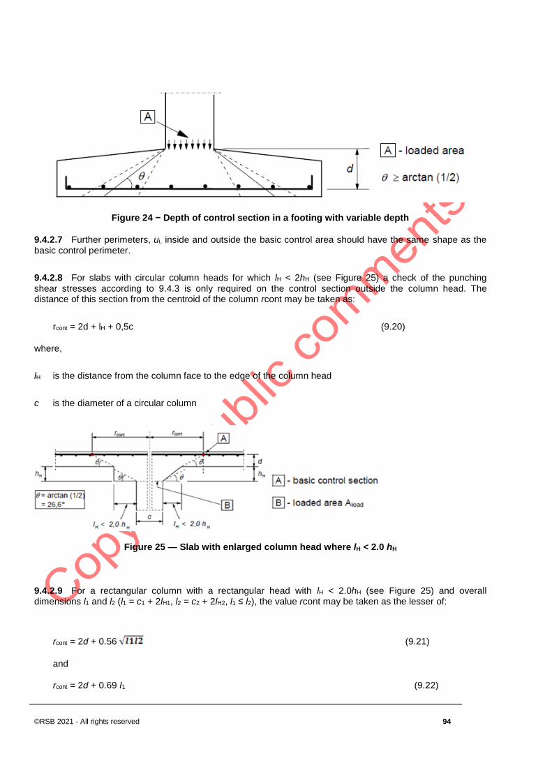
©RSB 2021 - All rights reserved 94
Figure 24 − Depth of control section in a footing with variable depth
9.4.2.7 Further perimeters, ui, inside and outside the basic control area should have the same shape as the basic control perimeter.
9.4.2.8 For slabs with circular column heads for which lH < 2hH (see Figure 25) a check of the punching shear stresses according to 9.4.3 is only required on the control section outside the column head. The distance of this section from the centroid of the column rcont may be taken as:
rcont = 2d + lH + 0,5c (9.20)
where,
lH is the distance from the column face to the edge of the column head
c is the diameter of a circular column
Figure 25 — Slab with enlarged column head where lH < 2.0 hH
9.4.2.9 For a rectangular column with a rectangular head with lH < 2.0hH (see Figure 25) and overall dimensions l1 and l2 (l1 = c1 + 2lH1, l2 = c2 + 2lH2, l1 ≤ l2), the value rcont may be taken as the lesser of:
rcont = 2d + 0.56 (9.21)
and
rcont = 2d + 0.69 I1 (9.22)

DRS 142: 2021
95 ©RSB 2021- All rights reserved
9.4.2.10 For slabs with enlarged column heads where lH > 2hH (see Figure 25) control sections both within the head and in the slab should be checked.
9.4.2.11 The provisions of 9.4.2 and 9.4.3 also apply for checks within the column head with d taken as dH according to Figure 25.
9.4.2.12 For circular columns the distances from the centroid of the column to the control sections in Figure 25 may be taken as:
rcont,ext = lH + 2d + 0,5c (9.23)
rcont,int = 2(d + hH) +0,5c (9.24)
9.4.3 Punching shear calculation
9.4.3.1 The design procedure for punching shear is based on checks at the face of the column and at the basic control perimeter u1.
If shear reinforcement is required a further perimeter uout,ef should be found where shear reinforcement is no longer required. The following design shear stresses (MPa) along the control sections are defined:
vRd,c is the design value of the punching shear resistance of a slab without punching shear reinforcement along the control section considered.
vRd,cs is the design value of the punching shear resistance of a slab with punching shear reinforcement along the control section considered.
vRd,max is the design value of the maximum punching shear resistance along the control section considered.
9.4.3.2 The following checks should be carried out:
a) At the column perimeter, or the perimeter of the loaded area, the maximum punching shear stress should not be exceeded:
vEd ≤ vRd,max
b) Punching shear reinforcement is not necessary if:
vEd ≤ vRd,c
c) Where vEd exceeds the value vRd,c for the control section considered, punching shear reinforcement should be provided according to 9.4.5.
9.4.3.3 Where the support reaction is eccentric with regard to the control perimeter, the maximum shear stress should be taken as:

©RSB 2021 - All rights reserved 96
(9.25)
where
d is the mean effective depth of the slab, which may be taken as (dy + dz)/2 where:
dy, dz is the effective depths in the y- and z- directions of the control section
ui is the length of the control perimeter being considered
β is given by:
(9.26)
where
u1 is the length of the basic control perimeter
k is a coefficient dependent on the ratio between the column dimensions c1 and c2: its value is a function of the proportions of the unbalanced moment transmitted by uneven shear and by bending and torsion (see Table 10).
W1 corresponds to a distribution of shear as illustrated in Figure 6.19 and is a function of the basic control perimeter u1:
(9.27)
dl is a length increment of the perimeter
e is the distance of dl from the axis about which the moment MEd acts
Table 11 — Values of k for rectangular loaded areas
C1/C2 ≤ 0.5 1.0 2.0 ≥ 3.0
K 0.45 0.60 0.70 0.80

DRS 142: 2021
97 ©RSB 2021- All rights reserved
Figure 26 — Shear distribution due to an unbalanced moment at a slab-internal column connection
9.4.3.4 For a rectangular column:
(9.28)
where:
c1 is the column dimension parallel to the eccentricity of the load
c2 is the column dimension perpendicular to the eccentricity of the load
For internal circular columns β follows from:
(9.29)
Where
D is the diameter of the circular column
e is the eccentricity of the applied load e = MEd / VEd
9.4.3.5 For an internal rectangular column where the loading is eccentric to both axes, the following approximate expression for β may be used:
(9.30)
where:

©RSB 2021 - All rights reserved 98
ey and ez are the eccentricities MEd/VEd along y and z axes respectively
by and bz is the dimensions of the control perimeter (see Figure 21).
NOTE ey results from a moment about the z axis and ez from a moment about the y axis.
9.4.3.6 For edge column connections, where the eccentricity perpendicular to the slab edge (resulting from a moment about an axis parallel to the slab edge) is toward the interior and there is no eccentricity parallel to the edge, the punching force may be considered to be uniformly distributed along the control perimeter u1* as shown in Figure 27(a).
a) edge column b) corner column
Figure 27 — Reduced basic control perimeter u1*
9.4.3.7 Where there are eccentricities in both orthogonal directions, β may be determined using the following expression:
(9.31)
where,
u1 is the basic control perimeter (see Figure 23)
u1* is the reduced basic control perimeter (see Figure 27(a))
epar is the eccentricity parallel to the slab edge resulting from a moment about an axis perpendicular to the slab edge.
k may be determined from Table 11 with the ratio c1/c2 replaced by c1/2c2

DRS 142: 2021
99 ©RSB 2021- All rights reserved
W 1 is calculated for the basic control perimeter u1 (see Figure 21).
For a rectangular column as shown in Figure 27(a):
(9.32)
9.4.3.8 If the eccentricity perpendicular to the slab edge is not toward the interior, Expression (9.26) applies. When calculating W1 the distance e should be measured from the centroid axis of the control perimeter.
9.4.3.9 For corner column connections, where the eccentricity is toward the interior of the slab, it is assumed that the punching force is uniformly distributed along the reduced control perimeter u1*, as defined in Figure 27(b). The β-value may then be considered as:
(9.33)
If the eccentricity is toward the exterior, Expression (9.21) applies.
9.4.3.10 For structures where the lateral stability does not depend on frame action between the slabs and the columns, and where the adjacent spans do not differ in length by more than 25%, approximate values for β may be used.
NOTE Recommended values of β are given in Figure 28.
Figure 28 — Recommended values for β

©RSB 2021 - All rights reserved 100
9.4.4 Punching shear resistance of slabs and column bases without shear reinforcement
9.4.4.1 The punching shear resistance of a slab should be assessed for the basic control section according to 9.34. The design punching shear resistance [MPa] may be calculated as follows:
(9.34)
where:
fck is in MPa
ρly, ρlz relate to the bonded tension steel in y- and z- directions respectively. The values
ρly and ρlz should be calculated as mean values taking into account a slab width equal to the column width plus 3d each side.
σcp = (σcy + σcz)/2
where
σcy, σcz are the normal concrete stresses in the critical section in y- and z directions (MPa, positive if compression):
NEdy, NEdz are the longitudinal forces across the full bay for internal columns and the longitudinal force across the control section for edge columns. The force may be from a load or prestressing action.
Ac is the area of concrete according to the definition of NEd
NOTE The recommended value for CRd,c is 0.18/ γc, for vmin is given by Expression (9.3) and that for k1 is 0.1.
9.4.4.2 The punching resistance of column bases should be verified at control perimeters within 2d from the periphery of the column.
9.4.4.2.1 For concentric loading the net applied force is
VEd,red = VEd – ΔVEd (9.35)

DRS 142: 2021
101 ©RSB 2021- All rights reserved
where
VEd is the applied shear force
ΔVEd is the net upward force within the control perimeter considered i.e. upward pressure from soil minus self weight of base.
vEd = VEd,red/ud
(9.36)
(9.37)
where
a is the distance from the periphery of the column to the control perimeter considered
CRd,c is defined in 9.4.4.1
Vmin is defined in 9.4.4.1
k is defined in 9.4.4.1
9.4.4.2.2 For eccentric loading
(9.38)
Where
k is defined in 9.4.3 (3) or 9.4.3 (4) as appropriate and W is similar to W1 but for perimeter u.
9.4.5 Punching shear resistance of slabs and column bases with shear reinforcement
9.4.5.1 Where shear reinforcement is required it should be calculated in accordance with Expression (9.39):
vRd,cs = 0.75 vRd,c + 1.5 (d/sr) Asw fywd,ef (1/(u1d)) sinα (9.39)
where
Asw is the area of one perimeter of shear reinforcement around the column [mm2]
sr is the radial spacing of perimeters of shear reinforcement [mm]

©RSB 2021 - All rights reserved 102
fywd,ef is the effective design strength of the punching shear reinforcement, according to fywd,ef = 250 + 0,25 d ≤ fywd [MPa]
d is the mean of the effective depths in the orthogonal directions [mm]
α is the angle between the shear reinforcement and the plane of the slab
If a single line of bent-down bars is provided, then the ratio d/sr in expression (9.34) may be given the value 0.67.
9.4.5.2 Detailing requirements for punching shear reinforcement are given in 9.4.3.
9.4.5.3 Adjacent to the column the punching shear resistance is limited to a maximum of:
(9.40)
where:
for an interior column, u0 = length of column periphery [mm]
for an edge column, u0 = c2 + 3d ≤ c2 + 2c1 [mm]
for a corner column, u0 = 3d ≤ c1 + c2 [mm]
c1, c2 are the column dimensions as shown in Figure 27
for β, see 9.4.3 (3), (4) and (5)
NOTE The recommended value of vRd,max is 0.5νfcd.
9.4.5.4 The control perimeter at which shear reinforcement is not required, uout (or uout,ef see Figure 6.22) should be calculated from expression (9.4.1):
uout,ef = βVEd / (vRd,c d) (9.41)
9.4.5.5 The outermost perimeter of shear reinforcement should be placed at a distance not greater than kd within uout (or uout,ef, see Figure 29).
where:
for an interior column ,u0 = length of column periphery [mm]

DRS 142: 2021
103 ©RSB 2021- All rights reserved
for an edge column, u0 = c2 + 3d ≤ c2 + 2c1 [mm]
for a corner column, u0 = 3d ≤ c1 + c2 [mm]
c1, c2 are the column dimensions as shown in Figure 27
ν, see Expression: v =0.6 ( fck in MPa)
β, see 6.4.3 (3), (4) and (5)
NOTE The recommended value is 0.5νfcd value of vRd,max.
9.4.5.6 The control perimeter at which shear reinforcement is not required, uout (or uout,ef see Figure 29) should be calculated from Expression (9.42):
uout,ef = βVEd / (vRd,c d) (9.42)
Figure 29 — Control perimeters at internal columns
NOTE The recommended value of k is 1.5.
9.5 Anchorages and laps
9.5.1 General
9.5.1.1 The design bond stress is limited to a value depending on the surface characteristics of the reinforcement, the tensile strength of the concrete and confinement of surrounding concrete. This depends on cover, transverse reinforcement and transverse pressure.
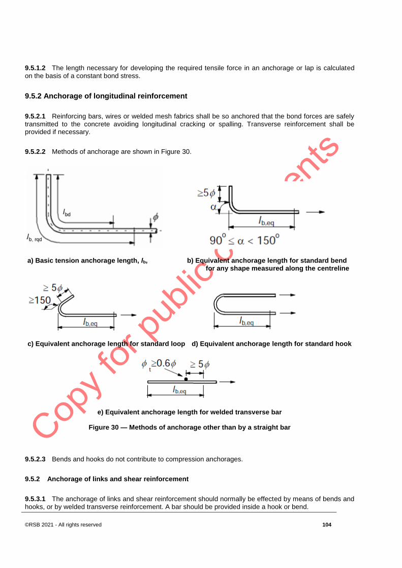
©RSB 2021 - All rights reserved 104
9.5.1.2 The length necessary for developing the required tensile force in an anchorage or lap is calculated on the basis of a constant bond stress.
9.5.2 Anchorage of longitudinal reinforcement
9.5.2.1 Reinforcing bars, wires or welded mesh fabrics shall be so anchored that the bond forces are safely transmitted to the concrete avoiding longitudinal cracking or spalling. Transverse reinforcement shall be provided if necessary.
9.5.2.2 Methods of anchorage are shown in Figure 30.
a) Basic tension anchorage length, lb, b) Equivalent anchorage length for standard bend for any shape measured along the centreline
c) Equivalent anchorage length for standard loop d) Equivalent anchorage length for standard hook
e) Equivalent anchorage length for welded transverse bar
Figure 30 — Methods of anchorage other than by a straight bar
9.5.2.3 Bends and hooks do not contribute to compression anchorages.
9.5.2 Anchorage of links and shear reinforcement
9.5.3.1 The anchorage of links and shear reinforcement should normally be effected by means of bends and hooks, or by welded transverse reinforcement. A bar should be provided inside a hook or bend.

DRS 142: 2021
105 ©RSB 2021- All rights reserved
9.5.3.1 The anchorage should comply with Figure 31. Welding should be carried out in accordance with ISO 17660.
NOTE For definition of the bend angles see Figure 30.
Figure 31 — Anchorage of links
NOTE For c) and d) the cover should not be less than either 3ϕ or 50 mm.
9.6 Fatigue
9.6.1 General
When the imposed load on a structure is predominantly cyclic in character, take the effects of fatigue into consideration in satisfying limit state requirements.
9.6.2 Verification conditions
9.6.2.1 The resistance of structures to fatigue shall be verified in special cases. This verification shall be performed separately for concrete and steel.
9.6.2.2 A fatigue verification should be carried out for structures and structural components which are subjected to regular load cycles (e.g. crane-rails, bridges exposed to high traffic loads).
9.6.3 Internal forces and stresses for fatigue verification
9.6.3.1 The stress calculation shall be based on the assumption of cracked cross sections neglecting the tensile strength of concrete but satisfying compatibility of strains.
9.6.3.2 The effect of different bond behaviour of prestressing and reinforcing steel shall be taken into account by increasing the stress range in the reinforcing steel calculated under the assumption of perfect bond by the factor, η, given by
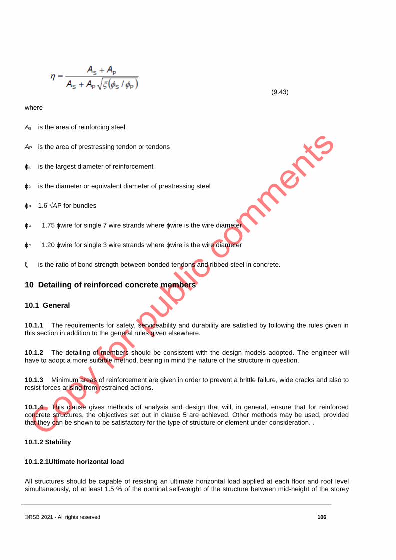
©RSB 2021 - All rights reserved 106
(9.43)
where
As is the area of reinforcing steel
AP is the area of prestressing tendon or tendons
ϕs is the largest diameter of reinforcement
ϕP is the diameter or equivalent diameter of prestressing steel
ϕP 1.6 √AP for bundles
ϕP 1.75 ϕwire for single 7 wire strands where ϕwire is the wire diameter
ϕP 1.20 ϕwire for single 3 wire strands where ϕwire is the wire diameter
ξ is the ratio of bond strength between bonded tendons and ribbed steel in concrete.
10 Detailing of reinforced concrete members
10.1 General
10.1.1 The requirements for safety, serviceability and durability are satisfied by following the rules given in this section in addition to the general rules given elsewhere.
10.1.2 The detailing of members should be consistent with the design models adopted. The engineer will have to adopt a more suitable method, bearing in mind the nature of the structure in question.
10.1.3 Minimum areas of reinforcement are given in order to prevent a brittle failure, wide cracks and also to resist forces arising from restrained actions.
10.1.4 This clause gives methods of analysis and design that will, in general, ensure that for reinforced concrete structures, the objectives set out in clause 5 are achieved. Other methods may be used, provided that they can be shown to be satisfactory for the type of structure or element under consideration. .
10.1.2 Stability
10.1.2.1Ultimate horizontal load
All structures should be capable of resisting an ultimate horizontal load applied at each floor and roof level simultaneously, of at least 1.5 % of the nominal self-weight of the structure between mid-height of the storey

DRS 142: 2021
107 ©RSB 2021- All rights reserved
below and either mid-height of the storey above or the roof surface. This force could be shared by the parts of the structure, depending on their stiffness and strength.
10.1.2.2 Safeguarding against vehicular impact
In order to obviate the possibility of vehicles running into and damaging or destroying vital load-bearing elements in the ground floor of a structure, the provision of elements such as bollards, walls and retaining earth banks should be considered.
10.1.2.3 Provision of ties
In structures where all load-bearing elements are of concrete, horizontal and vertical ties should be provided.
10.1.3 Durability and fire resistance
The durability and the fire resistance of reinforced concrete depend on the amount of concrete cover to reinforcement. Fire test results or other evidence may be used to ascertain the fire resistance of an element.
10.1.4 Loads
In this clause, the design load for the ultimate limit state is referred to as the ultimate load or the maximum design load, to avoid confusion with the service load, which is the design load for the serviceability limit states.
In design, use the values of the ultimate loads given in 10.7, and the values of the service loads given in 10.8.
10.1.5 Strength of materials
In this clause, the design strengths of materials for the ultimate limit state are expressed (in all the tables and equations) in terms of the characteristic strength of the material. Unless specifically stated otherwise, all equations and tables include allowances for γm, the partial safety factor for material strength.
10.1.5.1 Characteristic strength of concrete
The values of the 28 d characteristic strength of concrete, fcu, and the required strength of concrete at ages exceeding 28 d, for various grades of concrete, are given in Table 12.
Table 12 — Strength of concrete
Grade Characteristic
strength, fcu
MPa
Required strength at other ages
MPa
Age
Months
20 20.0 23 24 25
25 25.0 29 30 31
30 30.0 34 35 36
35 35.0 39 40 42

©RSB 2021 - All rights reserved 108
40 40.0 44 46 48
45 45.0 49 51 53
50 50.0 54 56 58
Design consideration should be based on the characteristic strength fcu, or, if relevant, on the appropriate strength given in table 12 for the age at loading.
For reinforced concrete, the lowest grade that should be used is 20 for concrete made with normal-weight aggregates and 15 for concrete made with lightweight aggregates.
10.1.5.2 Characteristic strength of reinforcement
Base the design on the appropriate characteristic strength of reinforcement given in table 13. (If necessary, a lower design stress may be used to help control deflection or cracking, and possibly a different grade of reinforcement may be used.)
Table 13 — Characteristic strength of reinforcement, fy
Designation of reinforcement Nominal size
mm
Characteristic strength fy
MPa
Hot rolled mild steel All sizes 250
Hot –rolled high-yield steel All sizes 450
Cold-work high-yield steel All sizes 450
Hard-drawn steel wire Up to and including 12 850
10.2 Bar spacing
10.2.1 The spacing of bars shall be such that the concrete can be placed and compacted satisfactorily for the development of adequate bond.
10.2.2 The clear distance (horizontal and vertical) between individual parallel bars or horizontal layers of parallel bars should be not less than the maximum of k1 bar diameter, (dg + k2 mm) or 20 mm where dg is the maximum size of aggregate.
NOTE The recommended values are of k1 and k2 are 1 mm and 5 mm respectively.
10.2.3 Where bars are positioned in separate horizontal layers, the bars in each layer should be located vertically above each other. There should be sufficient space between the resulting columns of bars to allow access for vibrators and good compaction of the concrete.
10.2.4 Lapped bars may be allowed to touch one another within the lap length.
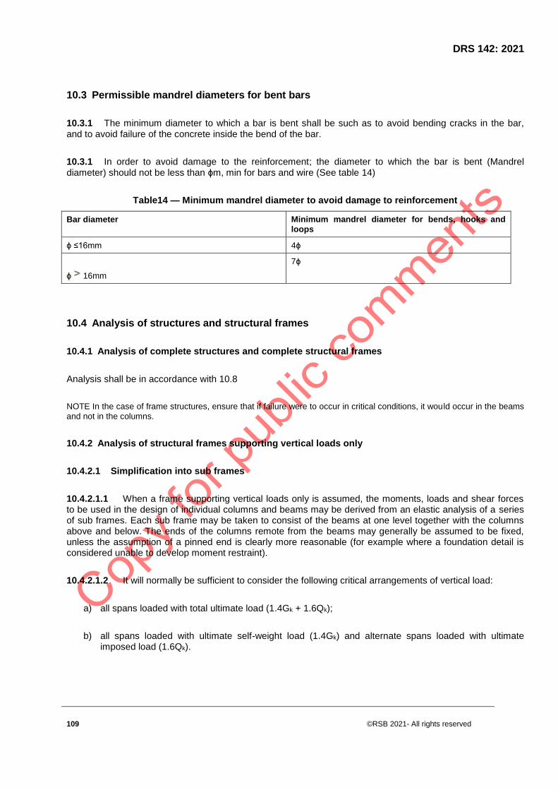
DRS 142: 2021
109 ©RSB 2021- All rights reserved
10.3 Permissible mandrel diameters for bent bars
10.3.1 The minimum diameter to which a bar is bent shall be such as to avoid bending cracks in the bar, and to avoid failure of the concrete inside the bend of the bar.
10.3.1 In order to avoid damage to the reinforcement; the diameter to which the bar is bent (Mandrel diameter) should not be less than ϕm, min for bars and wire (See table 14)
Table14 — Minimum mandrel diameter to avoid damage to reinforcement
Bar diameter Minimum mandrel diameter for bends, hooks and
loops
ϕ ≤16mm 4ϕ
ϕ 16mm
7ϕ
10.4 Analysis of structures and structural frames
10.4.1 Analysis of complete structures and complete structural frames
Analysis shall be in accordance with 10.8
NOTE In the case of frame structures, ensure that if failure were to occur in critical conditions, it would occur in the beams
and not in the columns.
10.4.2 Analysis of structural frames supporting vertical loads only
10.4.2.1 Simplification into sub frames
10.4.2.1.1 When a frame supporting vertical loads only is assumed, the moments, loads and shear forces to be used in the design of individual columns and beams may be derived from an elastic analysis of a series of sub frames. Each sub frame may be taken to consist of the beams at one level together with the columns above and below. The ends of the columns remote from the beams may generally be assumed to be fixed, unless the assumption of a pinned end is clearly more reasonable (for example where a foundation detail is considered unable to develop moment restraint).
10.4.2.1.2 It will normally be sufficient to consider the following critical arrangements of vertical load:
a) all spans loaded with total ultimate load (1.4Gk + 1.6Qk);
b) all spans loaded with ultimate self-weight load (1.4Gk) and alternate spans loaded with ultimate imposed load (1.6Qk).

©RSB 2021 - All rights reserved 110
10.4.2.2 Alternative simplification of sub frames (individual beams with associated columns)
10.4.2.2.1 The moments and forces in each individual beam may be found by considering a simplified sub frame consisting only of that beam, the columns attached to the ends of the beam and the beams on either side, if any. The column ends and the beam ends remote from the beam under consideration may generally be assumed to be fixed, unless the assumption of pinned ends is clearly more reasonable. The stiffness of the beams on either side of the beam under consideration should be taken as half their actual stiffness values if they are taken to be fixed at their outer ends.
10.4.2.2.2 The critical loading arrangements should be taken as follows:
a) all spans loaded with total ultimate load (1.4Gk + 1.6Qk);
b) all spans loaded with ultimate self-weight load (1.4Gk) and alternate spans loaded with ultimate imposed load (1.6Qk).
10.4.2.2.3 The moments in an individual column may also be found from this simplified sub frame, provided that the sub frame has at its central beam the longer of the two spans framing into the column under consideration.
10.4.2.3 "Continuous beam" simplification
As a more conservative alternative to the preceding sub frame arrangements, the moments and shear forces in the beams at one level may also be obtained by regarding the beams as a continuous beam over supports providing no restraint to rotation.
10.4.2.4 A symmetrically loaded columns where a beam has been analysed in accordance with 10.4.2.3
In these columns, the ultimate moments may be calculated by simple moment distribution procedures, on the assumption that the columns and beam ends remote from the junction under consideration are fixed and that the beams possess half their actual stiffness. The arrangement of the design ultimate imposed load should be such as to cause the maximum moment in the column.
10.4.2.5 Analysis of structural frames supporting vertical and lateral loads
10.4.2.5.1 When a frame provides lateral stability to the structure as a whole, it will be necessary to consider the effect of lateral loads. In addition, if the columns are slender, it may be necessary to consider additional moments (e.g. from eccentricity) that may be imposed on beams at beam column junctions.
10.4.2.5.2 In most cases, the design of individual beams and columns may be based either on the moments, loads and shears obtained by considering vertical loads only or on those obtained by considering both vertical and lateral loads.
10.4.2.5.3 An elastic analysis of a series of sub frames, each consisting of the beams at one level together with the columns above and below. The ends of the columns remote from the beams may generally be assumed to be fixed, unless the assumption of pinned ends is clearly more reasonable.
10.4.2.5.4 An Lateral loads should be ignored and all beams should be considered to be loaded as in 10.4.3.

DRS 142: 2021
111 ©RSB 2021- All rights reserved
10.4.2.5.5 An analysis of the complete frame, assuming points of contra flexure at the centres of all beams and columns, ignoring self-weight and imposed loads and considering only the design wind load on the structure. If more realistic, instead of assuming points of contra flexure at the centres of ground floor columns, the feet should be considered pinned.
10.4.3 Redistribution of moments
Redistribution of the moments obtained by elastic analysis or by the simplified methods given in 10.4.3. and 10.4.4 may be carried out, provided the following conditions are satisfied:
a) condition 1: equilibrium between internal and external forces is maintained under all appropriate combinations of ultimate load.
b) condition 2: where the design ultimate resistance moment of the cross-section subjected to the largest moment within each region of hogging or sagging is reduced, the neutral axis depth x should not exceed (βb-0.4)d
where
d is the effective depth; and
β is the moment at section after redistribution
b is the moment at section before redistribution < 1 from the respective maximum moments diagrams.
NOTE Unless the column axial load is small, condition 2 will generally rule out reduction in column moment.
c) condition 3: the ultimate resistance moment at any section of an element complies with the appropriate value obtained from the final envelope of redistributed elastic moments on the element, and the ultimate resistance moment at any section is at least 75 % or 80 %, as relevant, of the elastic moment at that particular section, obtained from elastic maximum moment diagrams covering all appropriate combinations of ultimate loads. The value of 75 % is applicable in the case of uniform elements (the cross-section considered does not change along the element). The value of 80 % is applicable in the case of non-uniform elements.
d) condition 4: in structures exceeding four storeys and in which the structural frame provides the lateral stability, the redistribution of moments is limited to 10 % and the value given in condition 3 reads 90 %.
e) condition 5: in the case of linear elastic analysis being used, the relative stiffness of the elements is not based on the transformed sections.
10.4.4 Column and beam construction
Any structural frame in a building provided with lateral stability by walls or bracing designed to resist all lateral forces may be considered to consist of continuous beams and columns.

©RSB 2021 - All rights reserved 112
10.5 Beams
10.5.1 General
10.5.1.1 Design limitation
Beams of normal proportions are the subject of this sub clause. In the case of beams of depth exceeding half of their clear span, specialist literature should be consulted.
10.5.1.2 Effective span of simply supported beams
The effective span of a simply supported beam is the smaller of:
a) the distance between the centres of bearings,
b) the clear distance between supports plus the effective depth.
10.5.1.3 Effective span of a continuous beam
The effective span of a continuous beam is the distance between the centres of supports. In the case of an embedded end, the centre of action of support should be taken to be half the effective depth from the face of the support.
10.5.1.4 Effective length of a cantilever
The effective length of a cantilever should be taken as its length to the face of the support plus half the effective depth. If a cantilever forms the end of a continuous beam, the effective span should be taken as its clear length plus the distance to the centre of the support.
10.5.1.5 Effective width of flanged beam
In the absence of a more accurate determination, ensure that the effective flange width
a) for a T-beam does not exceed the lesser of:
a. the web width plus L z /5 and
b. the actual width of the flange, and
b) for an L-beam does not exceed the lesser of:
1) the web width plus L z /10 and
2) the actual width of the flange,

DRS 142: 2021
113 ©RSB 2021- All rights reserved
where L z is the distance between points of zero moment (considering the bending moment envelope on spans). For a continuous beam, L z may be taken as 0,7 times the effective span.
10.5.1.6 Slenderness limits for beams
To ensure lateral stability, the clear distance between lateral restraints should not exceed the following:
a) for simply-supported and continuous beams, the lesser of 60bc and 250b2c /d; and
b) for cantilevers with lateral restraint provided only at the support, the lesser of 25bc and 100 b2c /d
where:
b is the width of the compression face of a beam midway between restraints, or width of the compression face of a cantilever; and
d is the effective depth.
For parapet beams, lateral restraint may be assumed to be provided by slabs attached to the tension zone, provided that the slab thickness is at least one-tenth of the effective depth of the parapet beam and the parapet beams themselves do not project above the slab by more than ten times their width.
For the relationship between slenderness limits for beams and the strength of concrete to be used, specialist literature should be consulted.
10.5.2 Longitudinal reinforcement of beams
10.5.2.1 Minimum and maximum reinforcement areas
10.5.2.1.1 The area of longitudinal tension reinforcement should not be taken as less than As,min
NOTE 1 See also 10.3 for area of longitudinal tension reinforcement to control cracking.
NOTE 2 The recommended value of As,min for beams is given in the following:
(11.1)
but not less than 0,0013btd
where:
bt denotes the mean width of the tension zone; for a T-beam with the flange in compression, only the width of the web is taken into account in calculating the value of bt.
fctm should be determined with respect to the relevant strength class according to Table 2.

©RSB 2021 - All rights reserved 114
Alternatively, for secondary elements, where some risk of brittle failure may be accepted, As,min may be taken as 1.2 times the area required in ULS verification.
10.5.2.1.2 Sections containing less reinforcement than As,min should be considered as unreinforced.
10.5.2.1.3 The cross-sectional area of tension or compression reinforcement should not exceed As,max
outside lap locations.
NOTE The recommended value value of As,max for beams is 0.04Ac.
10.5.2.1.4 For members prestressed with permanently unbonded tendons or with external prestressing cables, it should be verified that the ultimate bending capacity is larger than the flexural cracking moment. A capacity of 1.15 times the cracking moment is sufficient.
10.5.2.2 Other detailing arrangements
10.5.2.2.1 In monolithic construction, even when simple supports have been assumed in design, the section at supports should be designed for a bending moment arising from partial fixity of at least β1 of the maximum bending moment in the span.
NOTE 1 The recommended value of β1 for beams is 0.15.
NOTE 2 The minimum area of longitudinal reinforcement section defined in 10.5.2.1.1 applies.
10.5.2.2.2 At intermediate supports of continuous beams, the total area of tension reinforcement As of a flanged cross-section should be spread over the effective width of flange. Part of it may be concentrated over the web width (See figure 32).
Figure 32 — Placing of tension reinforcement in flanged cross-section.

DRS 142: 2021
115 ©RSB 2021- All rights reserved
10.5.2.2.3 Any compression longitudinal reinforcement (diameter ϕ) which is included in the resistance calculation should be held by transverse reinforcement with spacing not greater than 15ϕ.
10.5.2.3 Curtailment of longitudinal tension reinforcement
Sufficient reinforcement should be provided at all sections to resist the envelope of the acting tensile force, including the effect of inclined cracks in webs and flanges.
10.5.2.4 Anchorage of bottom reinforcement at an end supports
The area of bottom reinforcement provided at end supports with little or no end fixity assumed in design, should be at least β2 of the area of steel provided in the span.
NOTE The recommended value of β2 for beams is 0.25.
a) Direct support:
Beam supported wall or column
a) Indirect support:
Beam intersecting another supporting beam
Figure 33 −Anchorage of bottom reinforcement at end supports
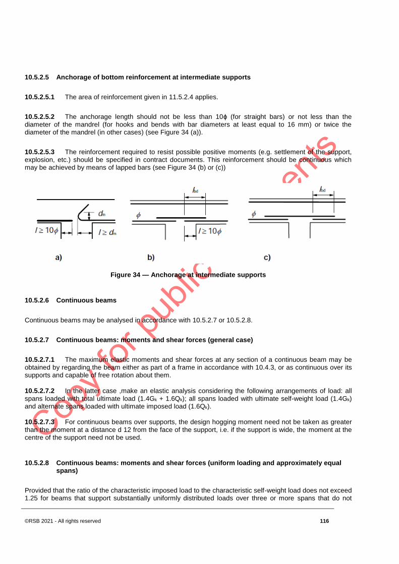
©RSB 2021 - All rights reserved 116
10.5.2.5 Anchorage of bottom reinforcement at intermediate supports
10.5.2.5.1 The area of reinforcement given in 11.5.2.4 applies.
10.5.2.5.2 The anchorage length should not be less than 10ϕ (for straight bars) or not less than the diameter of the mandrel (for hooks and bends with bar diameters at least equal to 16 mm) or twice the diameter of the mandrel (in other cases) (see Figure 34 (a)).
10.5.2.5.3 The reinforcement required to resist possible positive moments (e.g. settlement of the support, explosion, etc.) should be specified in contract documents. This reinforcement should be continuous which may be achieved by means of lapped bars (see Figure 34 (b) or (c))
Figure 34 — Anchorage at intermediate supports
10.5.2.6 Continuous beams
Continuous beams may be analysed in accordance with 10.5.2.7 or 10.5.2.8.
10.5.2.7 Continuous beams: moments and shear forces (general case)
10.5.2.7.1 The maximum elastic moments and shear forces at any section of a continuous beam may be obtained by regarding the beam either as part of a frame in accordance with 10.4.3, or as continuous over its supports and capable of free rotation about them.
10.5.2.7.2 In the latter case ,make an elastic analysis considering the following arrangements of load: all spans loaded with total ultimate load (1.4Gk + 1.6Qk); all spans loaded with ultimate self-weight load (1.4Gk) and alternate spans loaded with ultimate imposed load (1.6Qk).
10.5.2.7.3 For continuous beams over supports, the design hogging moment need not be taken as greater than the moment at a distance d 12 from the face of the support, i.e. if the support is wide, the moment at the centre of the support need not be used.
10.5.2.8 Continuous beams: moments and shear forces (uniform loading and approximately equal spans)
Provided that the ratio of the characteristic imposed load to the characteristic self-weight load does not exceed 1.25 for beams that support substantially uniformly distributed loads over three or more spans that do not

DRS 142: 2021
117 ©RSB 2021- All rights reserved
differ by more than 15 % from the longest span, the ultimate bending moments and shear forces used in design may be obtained from table 4.
10.5.2.9 Shear reinforcement
10.5.2.9.1 The shear reinforcement should form an angle α of between 45° and 90° to the longitudinal axis of the structural element.
10.5.2.9.2 The shear reinforcement may consist of a combination of:
a) links enclosing the longitudinal tension reinforcement and the compression zone (see Figure 35);
b) bent-up bars;
c) cages, ladders, etc. which are cast in without enclosing the longitudinal reinforcement but are properly anchored in the compression and tension zones.
Figure 35 — Examples of shear reinforcement
10.5.2.9.3 Links should be effectively anchored. A lap joint on the leg near the surface of the web is permitted provided that the link is not required to resist torsion.
10.5.2.9.4 At least β3 of the necessary shear reinforcement should be in the form of links.
NOTE The recommended value of β3 is 0.5.
10.5.2.9.5 The ratio of shear reinforcement is given by Expression (11.2):
ρw = Asw / (s . bw . sin α) (11.2)
where:
©RSB 2021 - All rights reserved 118
ρw is the shear reinforcement ratio
ρw should not be less than ρw,min
Asw is the area of shear reinforcement within length s
s is the spacing of the shear reinforcement measured along the longitudinal axis of the member
bw is the breadth of the web of the member
α is the angle between shear reinforcement and the longitudinal axis (see 10.5.2.9.1)
NOTE The recommended value of ρw,min is given Expression (11.3) .
(11.3)
where,
ρw is the shear reinforcement ratio
ρw should not be less than ρw,min
Asw is the area of shear reinforcement within length s
s is the spacing of the shear reinforcement measured along the longitudinal axis of the member
bw is the breadth of the web of the member
α is the angle between shear reinforcement and the longitudinal axis (see 10.5.2.9.1)
NOTE The recommended value of ρw,min is given in Expression (11.4).
(11.4)
10.5.3 Torsion reinforcement
10.5.3.1 The torsion links should be closed and be anchored by means of laps or hooked ends, see Figure 36, and should form an angle of 90° with the axis of the structural element.

DRS 142: 2021
119 ©RSB 2021- All rights reserved
a) recommended shapes b) not recommended shape
Figure 36 — Examples of shapes for torsion links
NOTE The second alternative for a2) (lower sketch) should have a full lap length along the top.
10.5.3.2 The provisions of 10.5.2.9 (5) is generally sufficient to provide the minimum torsion links required.
10.5.3.3 The longitudinal bars should be so arranged that there is at least one bar at each corner, the others being distributed uniformly around the inner periphery of the links, with a spacing not greater than 350 mm.
10.5.4 Surface reinforcement
It may be necessary to provide surface reinforcement either to control cracking or to ensure adequate resistance to spalling of the cover.
10.5.5 Indirect supports
10.5.5.1 Where a beam is supported by a beam instead of a wall or column, reinforcement should be provided and designed to resist the mutual reaction. This reinforcement is in addition to that required for other reasons. This rule also applies to a slab not supported at the top of a beam.
10.5.5.2 The supporting reinforcement between two beams should consist of links surrounding the principal reinforcement of the supporting member. Some of these links may be distributed outside the volume of the concrete, which is common to the two beams, (see Figure 37).

©RSB 2021 - All rights reserved 120
supporting beam with height h1
supported beam with height h2 (h1 ≥ h2)
Figure 37 — Placing of supporting reinforcement in the intersection zone of two beams (plan view)
Table 15 — Ultimate bending moments*) and shear forces
Position Moment shear
At outer support 0 0.45F
Near middle of end span
-
At first interior support
0.6F
At middle of interior support
-
At interior support
0.55F
*) Do not redistribute the moments obtained from the table.
NOTE F is the total ultimate load ( 1,4Gk+ 1,6 Qk) and l is the effective span
10.5.6 Moments of resistance at ultimate limit state for beams
10.5.6.1 Analysis of beams
10.5.6.1.1 When a cross-section of a beam is being analysed to determine its ultimate moment of resistance, the following assumptions should be made:
a. the strain distribution in the concrete in compression and the strains in the reinforcement, whether in tension or in compression, are derived from the assumption that plane sections remain plane;
b. the simplified stress diagram of concrete in compression is as shown in figure 38.
10.5.6.1.2 the strain at the outermost compression fibre is taken as 0.003 5; and
10.5.6.1.3 where beams are reinforced for tension only, the depth of the concrete in compression is limited to half the effective depth of the beam;
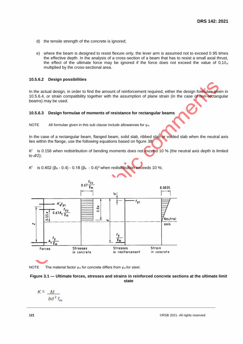
DRS 142: 2021
121 ©RSB 2021- All rights reserved
d) the tensile strength of the concrete is ignored;
e) where the beam is designed to resist flexure only, the lever arm is assumed not to exceed 0.95 times the effective depth. In the analysis of a cross-section of a beam that has to resist a small axial thrust, the effect of the ultimate force may be ignored if the force does not exceed the value of 0,1fcu multiplied by the cross-sectional area.
10.5.6.2 Design possibilities
In the actual design, in order to find the amount of reinforcement required, either the design formulae given in 10.5.6.4, or strain compatibility together with the assumption of plane strain (in the case of non-rectangular beams) may be used.
10.5.6.3 Design formulae of moments of resistance for rectangular beams
NOTE All formulae given in this sub clause include allowances for γm.
In the case of a rectangular beam, flanged beam, solid slab, ribbed slab or voided slab when the neutral axis lies within the flange, use the following equations based on figure 38:
K/ is 0.156 when redistribution of bending moments does not exceed 10 % (the neutral axis depth is limited to d/2);
K/ is 0.402 (βb - 0.4) - 0.18 (βb - 0.4)2 when redistribution exceeds 10 %;
NOTE The material factor γm for concrete differs from γm for steel.
Figure 3.1 — Ultimate forces, stresses and strains in reinforced concrete sections at the ultimate limit state

©RSB 2021 - All rights reserved 122
If K ≤ K /, only tension reinforcement is required and
x (d - z)/0,45
As M/0,87fyz;
If K > K , tension and compression reinforcement are required, and
x = (d - z)/0.45
In the case of a flanged beam where the neutral axis lies below the flange, the required steel area may be calculated from the following equation:
provided that the following requirements are met:
a) hf < 0,45d;
b) the design ultimate moment is less than βf fcu bd 2 (βf being as given in Table 5 below);
c) not more than 10 % of redistribution has been carried out (the neutral axis depth is limited to d/2).

DRS 142: 2021
123 ©RSB 2021- All rights reserved
Table 16 — Values of the factor βf
b/bw βf
d/hf
≤ 2 3 4 5 6 ∞
1 0.15 0.15 0.15 0.15 0.15 0.15
2 0.15 0.14 0.12 0.12 0.11 0.08
4 0.15 0.13 0.11 0.10 0.09 0.04
6 0.15 0.13 0.11 0.09 0.08 0.03
8 0.15 0.13 0.10 0.09 0.08 0.02
∞ 0.15 0.13 0.10 0.08 0.07 0
The ultimate design moment of resistance of a flanged beam where the neutral axis lies below the flange may be taken as the lesser of the values given by the following equations:
(11.5)
Where it is necessary for the moment of resistance to exceed the value given by equation (11.5).
10.5.7 Shear resistance of beams
All formulae given in this subclause include allowances for γm.
10.5.7.1 Shear stress and shear reinforcement in beams
10.5.7.1.1 The design shear stress v at any cross-section of a beam should in no case exceed a value of the lesser of 0.75√fcu or 4.75 MPa, regardless of any shear reinforcement provided.
Where:
V is the design shear force due to design maximum loads for ultimate limit state;
b is the width of section (for a flanged beam, should be taken as the rib width); and
d is the effective depth.
10.5.7.1.2 Where the shear stress exceeds vc as calculated from equation (11.6), provide shear reinforcement in the form of links or links combined with bent-up bars

©RSB 2021 - All rights reserved 124
10.5.7.1.3 Bent-up bars should not be spaced at more than 1,5 times the effective depth of the beam.
Calculate vc from:
( 11.6)
where:
γm is the partial safety factor for materials and fcu is the characteristic strength of concrete (but not exceeding 40 MPa),
should not be taken as greater than 3,
where:
As is the area of properly anchored tension reinforcement (in the case of prestressed concrete the stressed and unstressed reinforcement should be considered), and
bv is the width of section (for a flanged beam this should be taken as average width of the rib below the flange),
d is the effective depth.
10.5.7.1.4 Table 17 provides values of vc for 25 MPa concrete, for a typical range of steel contents and effective depths.
Table 17 − Maximum design shear stress, vc for grade 25 concrete
Maximum design shear stress of concrete, vc
MPa
Effective depth, d
mm
125 150 175 200 225 250 300 400 500 800
0.15 0.38 0.36 0.35 0.34 0.33 0.32 0.31 0.28 0.27 0.24
0.25 0.45 0.43 0.41 0.40 0.39 0.38 0.36 0.34 0.32 0.28
0.50 0.57 0.54 0.52 0.51 0.49 0.48 0.46 0.43 0.40 0.36
0.75 0.66 0.62 0.60 0.58 0.56 0.55 0.52 0.49 0.46 0.41
1.00 0.72 0.68 0.66 0.64 0.62 0.60 0.58 0.54 0.46 0.45
1.50 0.82 0.78 0.75 0.73 0.71 0.69 0.66 0.61 0.51 0.52
2.00 0.90 0.86 0.83 0.80 0.78 0.76 0.73 0.67 0.58 0.57

DRS 142: 2021
125 ©RSB 2021- All rights reserved
3.00 1.03 0.99 0.95 0.92 0.89 0.87 0.83 0.77 0.73 0.65
NOTE Allowance has been made in these figures for γm of 1.40
10.5.7.1.5 When links are used for shear reinforcement, ensure that the spacings of the legs (in the direction of the span and at right angles to it) do not exceed 0,75 d and that the following condition is satisfied:
fw is the characteristic strength of link reinforcement (but not exceeding 450 MPa);
Asv is the cross-sectional area of two legs of a link; and
Sv is the spacing of links along beam.
10.5.7.1.6 Up to 50 % of the shear reinforcement may be in the form of bent-up bars, which are assumed to form the tension members of one or more single systems of lattice girders in which the concrete forms the compression members. The maximum stress in any bar should be taken as 0.87f,.
10.5.7.1.7 The shear resistance in any vertical section is the sum of the vertical components of the tension and compression forces cut by the section.
10.5.7.1.8 The shear resistance of a single system of bent-up bars with the bars inclined at 45" or more, may be calculated from the following equation:
where,
Asb is the cross-sectional area of bent-up bars within the length of that part of a beam traversed by a shear failure plane;
fw, is the characteristic strength of bent-up bars (but not exceeding 450 MPa);
α,β are the angles as in figure 5; and
Sb is the spacing of bent-up bars (see figure 39).
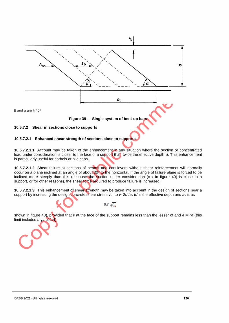
©RSB 2021 - All rights reserved 126
β and α are ≥ 45o
Figure 39 — Single system of bent-up bars
10.5.7.2 Shear in sections close to supports
10.5.7.2.1 Enhanced shear strength of sections close to supports
10.5.7.2.1.1 Account may be taken of the enhancement in any situation where the section or concentrated load under consideration is closer to the face of a support than twice the effective depth d. This enhancement is particularly useful for corbels or pile caps.
10.5.7.2.1.2 Shear failure at sections of beams and cantilevers without shear reinforcement will normally occur on a plane inclined at an angle of about 300 to the horizontal. If the angle of failure plane is forced to be inclined more steeply than this (because the section under consideration (x-x in figure 40) is close to a support, or for other reasons), the shear force required to produce failure is increased.
10.5.7.2.1.3 This enhancement of shear strength may be taken into account in the design of sections near a support by increasing the design concrete shear stress vc, to vc 2d /av (d is the effective depth and av is as
shown in figure 40), provided that v at the face of the support remains less than the lesser of and 4 MPa (this limit includes a γm of 1.4).

DRS 142: 2021
127 ©RSB 2021- All rights reserved
Figure 40 — Shear failure near supports
10.5.7.2.2 Shear reinforcement for section close to supports
If shear reinforcement is required, the total area of this is given by
where
av and dare as in 10.5.7.2.1;
bv is the width of section (for a flanged beam, this should be taken as average width of the rib below the flange);
v is the design shear stress at a cross-section;
vc is the design shear stress of concrete (see 10.5.7.1); and
fw is the characteristic strength of the link reinforcement (but not exceeding 450 MPa).
This reinforcement should be provided within the middle three-quarters of a,. Where a, is less than d, horizontal shear reinforcement will be more effective than will vertical, and both should be used.

©RSB 2021 - All rights reserved 128
10.5.7.2.3 Enhanced shear strength near supports
10.5.7.2.3.1 The procedures given in 10.5.7.2.1 and 10.5.7.2.2 may be used for all beams. However, for beams carrying a generally uniform load or where the principal load is located further than 2d from the face of support, the shear stress may be calculated at a section a distance from the face of the support.
10.5.7.2.3.2 The value of v, is calculated in accordance with 10.5.7.1, and the appropriate shear reinforcement assessed. If this amount of shear reinforcement is provided at sections closer to the support, no further check for shear at such sections is required.
10.5.7.3 Bottom loaded beams
Where load is applied through the side face below the neutral axis of a beam or the bottom of a beam, sufficient vertical reinforcement to carry the load up to the top face of the beam should be provided in addition to any reinforcement required to resist shear.
10.5.7.4 Shear and axial load
The design shear stress v/c that can be supported by a section v subjected to shear and to axial compression
without shear reinforcement can be calculated from the equation 11.7(a). Both adverse and beneficial load combinations should be considered
(11.7 (a))
where
N is the design axial force;
V is the design shear force due to ultimate loads;
H is the overall depth;
Ac is the gross area of concrete section. (N/Ac is intended to be the average stress in the concrete, acting at the centroid of the section); and
M is the design ultimate moment at the section under consideration.
The value of Vh/M should be taken as not greater than 1.
Where it is considered necessary to avoid shear cracking prior to the ultimate limit state, the shear stress should be limited to the value given by equation 11.7(b):
(11.7 (b)).

DRS 142: 2021
129 ©RSB 2021- All rights reserved
10.5.7.5 Torsional shear stress vt
10.5.7.5.1 Rectangular sections
The torsional shear stress vt at any section should be calculated assuming a plastic stress distribution and may be calculated from the following equation:
where:
T is the torsional moment due to design loads for the ultimate limit state;
Hmin is the smaller dimension of rectangular section; and
Hmax is the larger dimension of rectangular section.
10.5.7.5.2 T-, L- or I-sections
T-, L- or I-sections may be treated by dividing them into their component rectangles; these are chosen in such a way as to maximize h3
min x hmax, which will generally be achieved if the widest rectangle is made as long as possible.
Then 10.5.7.5.1 should be followed, bearing in mind that each of these component rectangles is subjected to a torsional moment as follows:
10.5.7.5.3 Reinforcement for torsion
10.5.7.5.3.1 Where the torsion shear stress vt exceeds the value vt,min in table 17, reinforcement should be provided.
10.5.7.5.3.2 In no case may the sum of the shear stresses resulting from shear force and torsion (v + vt) exceed the value vtu in table 17 nor, in the case of small sections (y1 < 550 mm), shall the torsion shear stress
vt exceed vtu y1/550, where y1 is the larger centre-to-centre dimension of a link.

©RSB 2021 - All rights reserved 130
Table 17 — Minimum and ultimate torsional shear stress in megapascals
Concrete grade Minimum torsional shear stress,
vtmin
Ultimate torsional shear stress, vtu
20* 0.27 3.18
25 0.30 3.56
30 0.33 4.00
≥40 0.36 4.50<vtu<4.75
*) Grade not recommended
NOTES
Allowance has been made in these figures for a γm of 1.40
Values of vtu are derived from the equation
vtu = but not exceeding 4.75 MPa.
Recommendations for reinforcement for combinations of shear and torsion are given in table 18.
Table 18 — Reinforcement for shear and torsion
vt ≤ vtmin
vt > vtmin
v≤ vc+0.4 Minimum shear reinforcement; no
torsion reinforcement
Designed torsion reinforcement but
not less than the minimum shear
reinforcement
v>vc+0.4 Designed shear reinforcement; no
torsion reinforcement
Designed shear and torsion
reinforcement
10.5.7.5.4 Area of torsional reinforcement
Torsional reinforcement should consist of rectangular closed links together with longitudinal reinforcement. This reinforcement is additional to any requirements for shear and bending and should be such that
where
Asv is the area of two legs of closed links at a section (in a section reinforced with multiple links, the area of the legs lying closest to the outside of the section should be used);
As is the area of longitudinal reinforcement;

DRS 142: 2021
131 ©RSB 2021- All rights reserved
Fyv is the characteristic strength of links (but not exceeding 450 MPa);
fy is the characteristic strength of longitudinal reinforcement (but not exceeding 450 MPa);
sv is the spacing of links;
x1 is the smaller centre-to-centre dimension of rectangular link; and
y1 is the larger centre-to-centre dimension of rectangular link.
10.5.7.5.5 Spacing and type of links
The spacing of the links sv should not exceed the least of x1, y1/2 and 200 mm.
10.5.7.5.6 Arrangement of longitudinal torsional reinforcement
Longitudinal torsional reinforcement should be distributed evenly round the inside perimeter of the links. The clear distance between these bars should not exceed 300 mm, and at least four bars, one in each corner of the links, should be used. Additional longitudinal reinforcement required at the level of the tension or compression reinforcement may be provided by using larger bars than those required for bending only. The torsional reinforcement should extend for a distance at least equal to the largest dimension of the section beyond where it theoretically ceases to be required.
10.5.7.5.7 Arrangement of links in T-, L- or I-sections
In the component rectangles, the reinforcement cages should be so detailed that they interlock and tie the component rectangles of the section together. Where the torsional shear stress in a minor component rectangle is less than vt,min, no torsional reinforcement need be provided in that rectangle.
10.5.8 Deflection of beams
10.5.8.1 General
10.5.8.1.1 Deflection may be calculated and compared with the serviceability requirements given ,but in all normal cases, the deflection of a beam will not be excessive if the ratio of its span to its effective depth does not exceed the appropriate ratio.
10.5.8.1.2 The deflection of the structure or of any part thereof should not exceed the permissible value. Permissible values of deflection should comply with the requirements of the particular structure, taking the efficient functioning of the structure, possible damage to adjacent structures or aesthetic considerations into account.
10.5.8.1.3 As a guide, the limits given below can be regarded as reasonable:
The final deflection (including the effects of temperature, creep and shrinkage), measured below the as-cast level of the support of floors, roofs and all other horizontal members, should not exceed span/250.
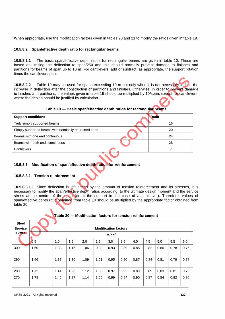
©RSB 2021 - All rights reserved 132
When appropriate, use the modification factors given in tables 20 and 21 to modify the ratios given in table 19.
10.5.8.2 Span/effective depth ratio for rectangular beams
10.5.8.2.1 The basic span/effective depth ratios for rectangular beams are given in table 10. These are based on limiting the deflection to span/250 and this should normally prevent damage to finishes and partitions for beams of span up to 10 m .For cantilevers, add or subtract, as appropriate, the support rotation times the cantilever span.
10.5.8.2.2 Table 19 may be used for spans exceeding 10 m but only when it is not necessary to limit the increase in deflection after the construction of partitions and finishes. Otherwise, in order to prevent damage to finishes and partitions, the values given in table 19 should be multiplied by 10/span, except for cantilevers, where the design should be justified by calculation.
Table 19 — Basic span/effective depth ratios for rectangular beams
Support conditions Ratio
Truly simply supported beams 16
Simply supported beams with nominally restrained ends 20
Beams with one end continuous 24
Beams with both ends continuous 28
Cantilevers 7
10.5.8.3 Modification of span/effective depth ratios for reinforcement
10.5.8.3.1 Tension reinforcement
10.5.8.3.1.1 Since deflection is influenced by the amount of tension reinforcement and its stresses, it is necessary to modify the span/effective depth ratios according to the ultimate design moment and the service stress at the centre of the span (or at the support in the case of a cantilever). Therefore, values of span/effective depth ratio obtained from table 19 should be multiplied by the appropriate factor obtained from table 20.
Table 20 — Modification factors for tension reinforcement
Steel
Service
stress
Modification factors
M/bd2
0.5 1.0 1.5 2.0 2.5 3.0 3.5 4.0 4.5 5.0 5.5 6.0
300 1.60 1.33 1.16 1.06 0.98
0.93
0.89
0.85
0.82
0.80
0.78
0.76
290 1.66 1.37 1.20 1.09 1.01
0.95
0.90
0,87
0.84
0.81
0.79
0.78
280 1.72 1.41 1.23 1.12 1.03 0.97 0.92 0.89 0.85 0,83 0.81 0.79
270 1.78 1.46 1.27 1.14 1.06
0.99
0.94
0.90
0.87
0.84
0.82
0.80

DRS 142: 2021
133 ©RSB 2021- All rights reserved
260 1.84 1.50 1.30 1.17 1.08
1.01
0.96
0.92
0.88
0.86
0.83
0,81
250 1.90 1.55 1.34 1.20 1.11 1.04 0.98 0.94 0.90 0.87 0.85 0.82
240 1.96 1.59 1.37 1.23 1.13
1.06
1.00
0.95
0.92
0.88
0.86
0.84
230 2.00 1.63 1.41 1.26 1.16
1.08
1.02
0.97
0.93
0.90
0.87
0.85
220 2.00 1.68 1.44 1.29 1.18 1.10 1.04 0.99 0.95 0.91 0.88 0.86
210 2.00 1.72 1.48 1.32 1.20
1.12
1.06
1.00
0.96
0.93
0.90
0.87
200 2.00 1.76 1.51 1.35 1.23
1.14
1.07
1.02
0.98
0.94
0.91
0.88
190 2.00 1.81 1.55 1.37 1.25 1.16 1.09 1.04 0.99 0.96 0.92 0.90
180 2.00 1.85 1.58 1.40 1.28
1.18
1.11
1.06
1.01
0.97
0.94
0.91
170 2.00 1.90 1.62 1.143 1.30
1.21
1.13
1.07
1.02
0.98
0.95
0.92
160 2.00 1.94 1.65 1.46 1.33 1.23 1.15 1.09 1.04 1.00 0.96 0.93
150 2.00 1.198 1.169 1.49 1.35
1.25
1.17
1.11
1.05
1.01
0.98
0.94
140 2.00 2.00 1.72 1.52 1.38
1.27
1.19
1.12
1.07
1.03
0.99
0.96
130 2.00 2.00 1.75 1.55 1.40
1.29
1.21
1.14
1.09
1.04
1.00
0.97
120 2.00 2.00 1.79 1.59 1.43 1.31 1.23 1.16 1.10 1.05 1.01 0.98
NOTES
1 The values in the table are based on the formula:
where;
M is the design ultimate moment at the centre of the span or, for cantilevers, at the support;
b is the width of section;
d is the effective depth of section; and
fs is the design estimate service stress in tension reinforcement.
2 For flanged beams, see 11.5.6.5
3 Span considered is smaller span for 2-way slabs, larger for flat slabs.
4 For flat plates (no drops), multiply factor by 0,9.
10.5.8.3.1.2 The design service stress in the tension reinforcement in a beam may be estimated from the following equation:
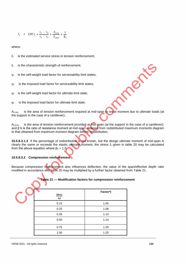
©RSB 2021 - All rights reserved 134
where:
fs is the estimated service stress in tension reinforcement;
fy is the characteristic strength of reinforcement;
γ1 is the self-weight load factor for serviceability limit states;
γ2 is the imposed load factor for serviceability limit states;
γ3 is the self-weight load factor for ultimate limit state;
γ4 is the imposed load factor for ultimate limit state;
As,req is the area of tension reinforcement required at mid-span to resist moment due to ultimate loads (at the support in the case of a cantilever);
As,prov is the area of tension reinforcement provided at mid-span (at the support in the case of a cantilever); and β b is the ratio of resistance moment at mid-span obtained from redistributed maximum moments diagram to that obtained from maximum moment diagram before redistribution.
10.5.8.3.1.3 If the percentage of redistribution is not known, but the design ultimate moment of mid-span is clearly the same or exceeds the elastic ultimate moment, the stress fs given in table 20 may be calculated from the above equation where βb = 1.0.
10.5.8.3.2 Compression reinforcement
Because compression reinforcement also influences deflection, the value of the span/effective depth ratio modified in accordance with table 20 may be multiplied by a further factor obtained from Table 21.
Table 21 — Modification factors for compression reinforcement
Factor*)
0.15 1.05
0.25 1.08
0.35 1.10
0.50 1.14
0.75 1.20
1.00 1.25
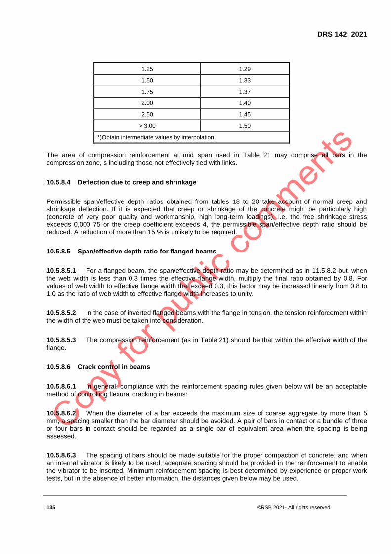
DRS 142: 2021
135 ©RSB 2021- All rights reserved
1.25 1.29
1.50 1.33
1.75 1.37
2.00 1.40
2.50 1.45
> 3.00 1.50
*)Obtain intermediate values by interpolation.
The area of compression reinforcement at mid span used in Table 21 may comprise all bars in the compression zone, s including those not effectively tied with links.
10.5.8.4 Deflection due to creep and shrinkage
Permissible span/effective depth ratios obtained from tables 18 to 20 take account of normal creep and shrinkage deflection. If it is expected that creep or shrinkage of the concrete might be particularly high (concrete of very poor quality and workmanship, high long-term loadings), i.e. the free shrinkage stress exceeds 0,000 75 or the creep coefficient exceeds 4, the permissible span/effective depth ratio should be reduced. A reduction of more than 15 % is unlikely to be required.
10.5.8.5 Span/effective depth ratio for flanged beams
10.5.8.5.1 For a flanged beam, the span/effective depth ratio may be determined as in 11.5.8.2 but, when the web width is less than 0.3 times the effective flange width, multiply the final ratio obtained by 0.8. For values of web width to effective flange width that exceed 0.3, this factor may be increased linearly from 0.8 to 1.0 as the ratio of web width to effective flange width increases to unity.
10.5.8.5.2 In the case of inverted flanged beams with the flange in tension, the tension reinforcement within the width of the web must be taken into consideration.
10.5.8.5.3 The compression reinforcement (as in Table 21) should be that within the effective width of the flange.
10.5.8.6 Crack control in beams
10.5.8.6.1 In general, compliance with the reinforcement spacing rules given below will be an acceptable method of controlling flexural cracking in beams:
10.5.8.6.2 When the diameter of a bar exceeds the maximum size of coarse aggregate by more than 5 mm, a spacing smaller than the bar diameter should be avoided. A pair of bars in contact or a bundle of three or four bars in contact should be regarded as a single bar of equivalent area when the spacing is being assessed.
10.5.8.6.3 The spacing of bars should be made suitable for the proper compaction of concrete, and when an internal vibrator is likely to be used, adequate spacing should be provided in the reinforcement to enable the vibrator to be inserted. Minimum reinforcement spacing is best determined by experience or proper work tests, but in the absence of better information, the distances given below may be used.

©RSB 2021 - All rights reserved 136
10.5.8.6.4 In certain cases, particularly where groups of bars are used, advantage may be gained from calculating crack widths and comparing them with the recommended values given in limit state design.( See relevant clause).
10.6 Solid slabs
10.6.1 Design of solid slabs
This clause applies to one-way and two-way solid slabs for which b and leff are not less than 5h. In general, the recommendations given in 11.6.2 and the relevant clause of crack control for beams will apply and taken into account also to solid slabs
10.6.2 Moments and forces in solid slabs
10.6.2.1 General
In solid slabs, the moments and shear forces resulting from both distributed and concentrated loads may be found as for beams.
10.6.2.2 Resistance moments of solid slabs
The ultimate moment of resistance of a cross-section in a solid slab may be determined by using the methods given in 11.5.6 for beams.
10.6.2.3 Simplification of load arrangements
10.6.2.3.1 A continuous slab will be able to withstand the most unfavourable arrangements of design loads if it is designed to resist the moments and forces arising from the single-load case of maximum design load on all spans. The following conditions are to be met:
a) in a one-way spanning slab, the area of each bay exceeds 30 m2.
NOTE In this context, a bay is a strip across the full width of a structure and supported on two sides (see figure 41).
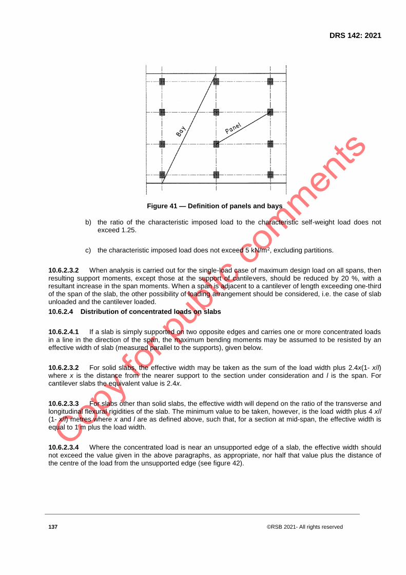
DRS 142: 2021
137 ©RSB 2021- All rights reserved
Figure 41 — Definition of panels and bays
b) the ratio of the characteristic imposed load to the characteristic self-weight load does not exceed 1.25.
c) the characteristic imposed load does not exceed 5 kN/m2, excluding partitions.
10.6.2.3.2 When analysis is carried out for the single-load case of maximum design load on all spans, then resulting support moments, except those at the support of cantilevers, should be reduced by 20 %, with a resultant increase in the span moments. When a span is adjacent to a cantilever of length exceeding one-third of the span of the slab, the other possibility of loading arrangement should be considered, i.e. the case of slab unloaded and the cantilever loaded.
10.6.2.4 Distribution of concentrated loads on slabs
10.6.2.4.1 If a slab is simply supported on two opposite edges and carries one or more concentrated loads in a line in the direction of the span, the maximum bending moments may be assumed to be resisted by an effective width of slab (measured parallel to the supports), given below.
10.6.2.3.2 For solid slabs, the effective width may be taken as the sum of the load width plus 2.4x(1- x/l) where x is the distance from the nearer support to the section under consideration and l is the span. For cantilever slabs the equivalent value is 2.4x.
10.6.2.3.3 For slabs other than solid slabs, the effective width will depend on the ratio of the transverse and longitudinal flexural rigidities of the slab. The minimum value to be taken, however, is the load width plus 4 x/l (1- x/l) metres where x and l are as defined above, such that, for a section at mid-span, the effective width is equal to 1 m plus the load width.
10.6.2.3.4 Where the concentrated load is near an unsupported edge of a slab, the effective width should not exceed the value given in the above paragraphs, as appropriate, nor half that value plus the distance of the centre of the load from the unsupported edge (see figure 42).

©RSB 2021 - All rights reserved 138
Figure 42 — Effective width of solid slab carrying a concentrated load near an unsupported edge
10.6.3 One-way spanning slabs of approximately equal span
10.6.3.1 Where the length of the longer side of a slab exceeds three times the length of the shorter side, so design the slab as to span one way only.
10.6.3.2 When the conditions of simplification of load arrangements (see 11.6.2.3) are met, the moments and shears in continuous one-way spanning slabs may be calculated using the coefficients given in Table 13.
Table 22 — Ultimate bending moments and shear forces in one-way spanning slabs
Position of slab connection Moment Shear
At outer support 0 0.4F
Near middle of end span 0.086Fl -
At first interior support -0.086Fl 0.6F
At middle of interior span 0.063Fl -
At interior supports -0. 063Fl 0.5F
NOTE F is the total ultimate load (1.4Gk+1.6Qk)
L is the effective span
10.6.4 Solid slabs spanning in two directions at right angles (uniformly distributed loads)
In addition to other methods, the methods given 11.6.4.1 to 11.6.4.3 may be used for the design of slabs spanning in two directions at right angles and supporting uniformly distributed loads.

DRS 142: 2021
139 ©RSB 2021- All rights reserved
10.6.4.1 Simply supported slabs
10.6.4.1.1 When simply supported rectangular slabs do not have adequate provision to resist torsion at the corners and to prevent the corners from lifting, the maximum moments per unit width are given by the following equations:
where:
Msx, Msy are the maximum bending moments at mid-span on strips of unit width spanning lx and ly respectively;
n is the total ultimate load per unit area (1,4 gk + 1,6 qk);
lx is the length of shorter side;
ly is the length of larger side; and
αsx, αsy are the bending moment coefficients given in table 23.
10.6.4.1.2 Extend to the supports at least 50 % of the tension reinforcement provided at mid-span. Extend the remaining part of the reinforcement to within 0,1lx or 0,1ly of the support, as appropriate.
Table 22 — Bending moment coefficients for slabs spanning in two directions at right angles, simply supported on four sides
αsx αsy
1.0 0.045 0.045
1.1 0.061 0.038
1.2 0.071 0.031
1.3 0.080 0.027
1.4 0.087 0.023
1.5 0.092 0.020
1.6 0.097 0.017
1.7 0.100 0.015
1.8 0.102 0.016
1.9 0.103 0.016
2.0 0.104 0.016
2.5 0.108 0.016

©RSB 2021 - All rights reserved 140
3.0 0.111 0.017
10.6.4.2 Restrained slabs
Both in continuous and in discontinuous slabs where the corners are prevented from lifting and provision for torsion is made, the maximum moments per unit width are given by the following equations:
(10.8)
(10.9)
where
Msx, Msy are the maximum bending moments at mid-span on strips of unit width spanning lx and Ly respectively;
n is the total ultimate load per unit area (1.4gk+ 1.6 qk);
lx is the length of shorter side;
ly is the length of larger side; and
βsx, βsy are the bending moment coefficients given in Table 23.
Table 23 — Bending moment coefficients for rectangular panels supported on four sides with provision for torsional reinforcement at the corners
Ca
se
Type of panel and moments
considered Short span coefficients βsx Long
span coeffic
ients,
βsy
Values of ly/lx
1.0 1.1 1.2 1.3 1.4 1.5 1.75 2.0
1 Interior panels
Negative moment at continuous
edge
0.031
0.037
0.042
0.046
0.050
0.053
0.059
0.063
.032
Positive moment at mid- span 0.024 0.028 0.032 0.036 0.039 0.041 0.045 0.049 0.024
2 One short edge discontinuous
Negative moment at continuous
edge
0.039
0.044
0.048
0.052
0.055
0.058
0.063
0.067
0.037
Positive moment at mid-span 0.029 0.033 0.036 0.039 0.041 0.043 0.047 0.050 0.028
3 One long edge discontinuous
Negative moment at continuous.
0.039
0.049
0.056
0.062
0.068
0.073
0.082
0.089
0.037
Positive moment at mid-span 0.030 0.036 0.042 0.047 0.051 0.055 0.062 0.067 0.028
4 Two adjacent edges 0.047 0.056 0.063 0.069 0.074 0.078 0.087 0.092 0.045

DRS 142: 2021
141 ©RSB 2021- All rights reserved
discontinuous
Negative moment at continuous
edge
Positive moment at mid-span 0.036 0.042 0.047 0.051 0.055 0.059 0.065 0.070 0.034
5 Two short edges discontinuous
Negative moment at continuous
edge
0.046
0.050
0.054
0.057
0.060
0.062
.067
0.070
-
Positive moment at mid-span 0.034 0.038 0.040 0.043 0.045 0.045 0.047 0.053 0.034
6 Two long edges discontinuous
Negative moment at continuous
edge
-
-
-
-
-
-
-
-
0.045
Positive moment at mid-span 0.034 0.046 0.056 0.065 0.072 0.078 0.091 0.100 0.034
7 Three edges discontinuous (one
long edge continuous)
Negative moment at continuous
edge
0.057
0.065
0.071
0.076
0.080
0.084
0.092
0.098
-
Positive moment at mid-span 0.043 0.048 0.053 0.057 0.060 0.063 0.069 0.074 0.044
8 Three edges discontinuous (one
short edge continuous)
Negative moment at continuous
edge
-
-
-
-
-
-
-
-
0.058
Positive moment at mid-span 0.042 .,054 0.063 0.071 0.078 0.084 0.096 0.105 0.044
9 Four edges discontinuous
Positive moment at mid-span
0.055 0.065 0.074 0.081 0.087 0.092 0.103 0.111 0.056
10.6.4.2.1 In the case of continuous slabs
The nominal self-weight and imposed loads on adjacent slabs should be approximately the same as those on the slab under consideration, and the spans of all adjacent slabs should be approximately the same in each of the two directions of the lines of the supports.
10.6.4.2.2 In the case of continuous and discontinuous slabs
Regard slabs as divided in each direction into middle strips and edge strips as shown in Figure 43, the middle strip being three-quarters of the width and each edge strip one-eighth of the width.
The maximum moments calculated as in 10.6.4.2 apply to the middle strips only and no redistribution is permitted.

©RSB 2021 - All rights reserved 142
a) For span lx b) For span ly
Figure 43 — Division of slab into middle and edge strips
a. tension reinforcement at mid-span: extend at least 50 % of the tension reinforcement provided at mid-span in the middle strip in the lower part of the slab to within 0,15l of the continuous edge axis, and to within 50 mm of the discontinuous edge axis; extend the remaining part of the reinforcement to within 0.25l of a continuous edge axis, and to within 0.15l of the discontinuous edge axis;
b. tension reinforcement over the continuous edges: extend at least 50 % of the tension reinforcement provided in the upper part of a middle strip to a distance 0.3l from the face of the support; extend the remaining part of the reinforcement to a distance of 0.15l from the face of the support;
c. tension reinforcement over the discontinuous edge: at a discontinuous edge, negative moments may arise, depending on the degree of fixity of the edge of the slab; in general, tension reinforcement equal to 50 % of that provided at mid-span extending 0.1l into the span (from the face of the support) will be sufficient;
d. tension reinforcement in an edge strip, parallel to the edge: the reinforcement need not exceed the minimum given in the rules for torsional reinforcement given in (e), (f) and (g) below;
e. torsional reinforcement at any corner where the slab is simply supported on both edges meeting at that corner: the reinforcement should comprise top and bottom reinforcement, each with layers of bars placed parallel to the sides of the slab and extending from the external faces of the edges a minimum distance of one-fifth of the shorter span; the area of reinforcement in each of these four layers should be three-quarters of the area required for the maximum mid-span moment in the slab;
f. torsional reinforcement at any corner contained by edges over only one of which the slab is continuous: reinforcement equal to half of that described in (e) above should be provided;
g. torsional reinforcement need not be provided at any corner contained by edges over both of which the slab is continuous: where ly /lx exceeds 3, so design slabs as to span one way only.

DRS 142: 2021
143 ©RSB 2021- All rights reserved
10.6.4.2.3 In the case of a restrained slab with unequal conditions at adjacent panels
10.6.4.2.3.1 If the support moments for adjacent panels (calculated using Table 23) differ significantly, they may be adjusted as follows
a) calculate the sum of the moments at mid-span and supports (ignoring signs);
b) treat the values from table 15 as fixed end moments;
c) distribute these fixed end moments across the supports according to the relative stiffness of adjacent spans, giving new support moments;
d) adjust the mid-span moment; this should be such that when it is added to the support moments as in (c) above (ignoring signs), the total should equal that obtained in (a) above;
10.6.4.2.3.2 If, for a given panel, the resulting support moments now significantly exceed the values given by equations (10.8) and (10.9).
The procedure is as follows:
1) the span moment is taken as parabolic between supports; its maximum value is as found in (d) above;
2) the points of contra flexure of the new support moments (as in (c) above) and the span moment (as in (1) above) are determined;
3) at each end, half the support tension steel is extended to at least an effective depth or 12 bar diameters beyond the nearest point of contra flexure; and
4) at each end, the full area of the support tension steel is extended to half the distance obtained in (3) above.
10.6.4.3 Loads on supporting beams
The design loads on beams supporting solid slabs spanning in two directions at right angles and supporting uniformly distributed loads may be assumed to be in accordance with Figure 10. If the edges of two slabs having the same support meet at a corner, the dividing angle is 45°. If a fully restrained edge meets a freely supported edge, the dividing angle on the restrained side is 60°. With partial restraint, the angles may be assumed to lie between 45° and 60° (see figure 44(b)).

©RSB 2021 - All rights reserved 144
(a) ( b)
Figure 44 — Apportionment of load for determining the bearing reactions
10.6.5 Shear resistance of solid slabs
10.6.5.1 Shear stresses in solid slabs
10.6.5.1.1 The design shear stress v at any cross-section in a solid slab should be compared with the
allowable shear stress vc and in no case should it exceed the lesser of or 4.75MPa,whatever
reinforcement is provided.
Calculate v from (10.10)
where
v is the design shear stress;
V is the shear force due to design maximum loads;
B is the width of slab under consideration (usually 1 000 mm); and
d is the effective depth; and the allowable stress vc is the maximum design shear stress in concrete without shear reinforcement.
10.6.5.1.2 When the design shear stress v is less than the allowable shear stress vc, no shear reinforcement is needed.
10.6.5.1.3 When v exceeds vc, shear reinforcement should be provided in accordance with the appropriate rules for beams.

DRS 142: 2021
145 ©RSB 2021- All rights reserved
10.6.5.1.4 It may be assumed that every 10 mm reduction in the slab thickness reduces the links' efficiency by 10 %. The enhancement in design shear strength close to supports may also be applied to solid slabs.
10.6.5.2 Shear stresses in solid slabs under concentrated load
10.6.5.2.1 The following terms specific to perimeters are used in this sub clause:
a) perimeter: a boundary of the smallest rectangle (or square) that can be drawn around a loaded area and that nowhere comes closer to the edges of the loaded area than some specified distance lp (a multiple of 0.75d) (see figure 45).
b) failure zone: an area of slab bounded by perimeters 1.5d apart ;
c) effective length of a perimeter: the length of the perimeter reduced, where appropriate, for the effects of openings or external edges;
d) effective depth d: the average effective depth for all effective reinforcement passing through a perimeter; and
e) effective steel area: the total area of all tension reinforcement that passes through a zone and that extends at least one effective depth (see above) or 12 times the bar size beyond the zone on either side.
NOTE The reinforcement percentage used to calculate the design ultimate shear stress vc is given by:
where:
u is the outer perimeter of zone concerned; and
d is the effective depth (as defined above).
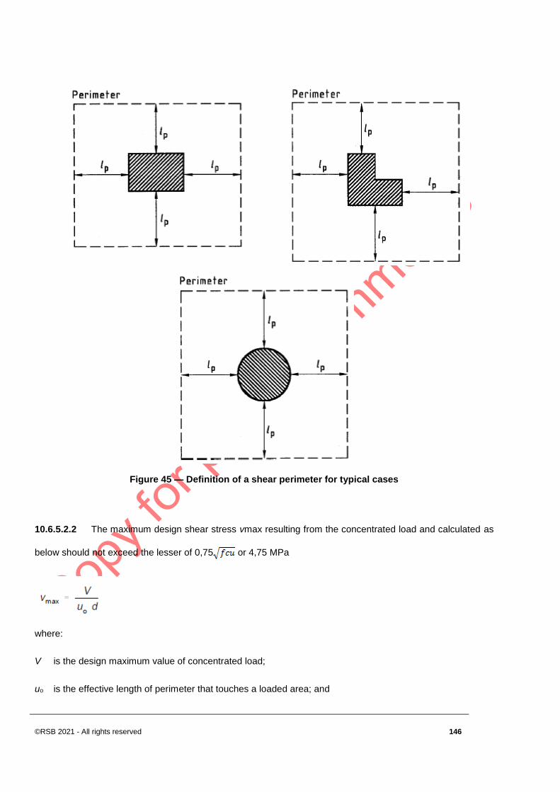
©RSB 2021 - All rights reserved 146
Figure 45 — Definition of a shear perimeter for typical cases
10.6.5.2.2 The maximum design shear stress vmax resulting from the concentrated load and calculated as
below should not exceed the lesser of 0,75 or 4,75 MPa
where:
V is the design maximum value of concentrated load;
uo is the effective length of perimeter that touches a loaded area; and

DRS 142: 2021
147 ©RSB 2021- All rights reserved
d is the effective depth of slab.
10.6.5.2.3 The shear capacity of punching shear zones is checked first on a perimeter 1.5 d from the face of the loaded area. If the calculated shear stress does not exceed vc, then no further checks are needed.
10.6.5.2.4 The spacing of perimeters of reinforcement should not exceed 0.75d and the spacing of the shear reinforcement around any perimeter should not exceed 1.5d. The shear reinforcement should be anchored round at least one layer of tension reinforcement. The shear stress should then be checked on successive perimeters at 0.75d intervals until a perimeter is reached which does not require shear reinforcement.
10.6.5.2.5 The nominal design shear stress v, appropriate to a particular perimeter, is calculated from:
where
V, d are as in equation (20); and
u is the effective length of the outer perimeter of the zone.
No shear reinforcement is required when the stress v is less than vc.
10.6.5.2.6 In the case of zone 1, As in each direction should include all the tension reinforcement within a strip of width bv equal to the width of the loaded area plus three times the effective depth of slab on either side of the loaded area.
10.6.6 Deflection of solid slabs
10.6.6.1 Deflections may be calculated and compared with the serviceability provisions, but in all normal cases, it will be sufficient to restrict the span/effective depth ratio. The appropriate ratio for a solid slab may be obtained from table 19, modified by tables 20 and 21. The reinforcement at the middle of the span in the width of the slab under consideration should be considered to influence deflection.
10.6.6.2 In the case of a two-way spanning slab, the ratio should be based on the shorter span and its amount of reinforcement in that direction.
10.6.7 Crack control in solid slabs
In general, compliance with the reinforcement spacing rules given relevant clause will be an acceptable method of controlling flexural cracking in slabs but, in certain cases, advantage may be gained from calculating crack widths and comparing them with the recommended values given in limit state design.

©RSB 2021 - All rights reserved 148
10.6.8 Ribbed slabs (with solid or hollow blocks or with voids)
10.6.8.1 General
10.6.8.1.1 Construction
This sub clause refers to in-situ slabs constructed in one of the following ways:
a) where topping is considered to contribute to structural strength:
i. as a series of concrete ribs cast in situ between blocks that remain part of the completed structure; the tops of the ribs are connected by a topping of concrete of the same strength as that used in the ribs;
ii. as a series of concrete ribs with topping cast on forms that may be removed after the concrete has set;
iii. with a continuous top and bottom face but containing voids of rectangular, oval or other shape.
b) where topping is not considered to contribute to structural strength: as a series of concrete ribs cast in-situ between blocks that remain part of the completed structure; the tops of the ribs may be connected by a topping of concrete but not necessarily of the same strength as that used in the ribs.
10.6.8.1.2 Thickness of topping
When a topping is used to contribute to the structural strength, ensure that its thickness, after any necessary allowance has been made for wear, is at least
a) 30 mm for slabs that have permanent blocks and have a clear distance of not more than 500 mm between the ribs;
b) 25 mm for slabs as in (a) above but with each row of blocks jointed in mortar having a cement-sand mixture not weaker than 1:3, or having a cube strength of 11 MPa;
c) the greater of 40 mm or one-tenth of the clear distance between the ribs, for all other slabs containing permanent blocks;
d) the greater of 50 mm or one-tenth of the clear distance between the ribs, for all other slabs without permanent blocks.
10.6.8.2 Size, spacing and position of ribs
10.6.8.2.1 The minimum width of ribs, whether they are rectangular or tapered, should be at least 65 mm and their depth, excluding any topping, should not exceed four times their width.
10.6.8.2.2 In-situ ribs should be spaced at centres not exceeding 1.5 m and the edge rib that bears along its length on a beam or wall shall be at least as wide as the bearing, i.e. the block or void shall not be on the bearing.

DRS 142: 2021
149 ©RSB 2021- All rights reserved
10.6.8.3 Hollow blocks and formers
10.6.8.3.1 Blocks and formers may be of any suitable material but, when required to contribute to the structural strength of a slab, they should be made of:
a) concrete or burnt clay and have a crushing strength of at least 14 MPa measured on the net section when axially loaded in the direction of compressive stress in the slab, or
b) fired briquettes, clay or shale.
10.6.8.3.2 When a slab is constructed in accordance with 10.6.8.1.2 (a) but the topping is not used to contribute to structural strength, the blocks should comply with 10.6.8.1.4 (a) or (b). In addition, the thickness of the block material above its void shall be the greater of at least 20 mm or one-tenth of the clear distance between the ribs. The overall thickness of the block and topping (if any) should be not less than one-fifth of the clear distance between the ribs.
10.6.8.3.1 Analysis of structure
The moments and forces due to ultimate loads on continuous slabs may be obtained by any of the methods given in 10.6.2 for solid slabs. Alternatively, the slabs may be designed as a series of simply supported spans, provided that they will not be exposed to weather or corrosive conditions. Wide cracks may develop at the supports and the engineer shall satisfy himself that these will not impair finishes or lead to corrosion of the reinforcement. Rules for the arrangement of reinforcement are given in the clause of arrangement of reinforcement.
10.6.8.3.2 Moments of resistance
The methods given in 4.3.3 for determining the ultimate moment of resistance of beams may be used. When sections are being analysed, the stresses in burnt clay blocks in the compression zone may be taken as 0.25 times the strength as determined in 11.6.8.1.4(a). However, when evidence is available to show that not more than 5 % of the blocks have a strength below a specified crushing strength, the stress may be taken as 0.3 times that strength.
10.6.8.3.3 Shear
10.8.8.3.3.1 In one-way or two-way spanning slabs, the design shear stress v should be calculated from the following equation:
where
V is the design shear force due to design ultimate loads on a width of slab equal to the centre-to-centre distance between ribs;
bv is the average width of rib; and

©RSB 2021 - All rights reserved 150
d is the effective depth.
10.8.8.3.3.2 In the determination of bv, the following shear contribution cases should be taken into consideration:
a) shear contribution by hollow blocks: bv may be increased by the wall thickness of the block, on one side of the rib;
b) shear contribution by solid blocks: when blocks comply with 10.6.8.1.4, bv may be increased by one-half of the rib depth, on each side of the rib;
c) shear contribution by joints between narrow precast units: bv may be increased by the width of the mortar or concrete joint.
10.8.8.3.3.3 When v is less than vc, where vc is obtained from 10.6.8.1.4, no shear reinforcement need be provided.
10.8.8.3.3.4 Where a critical perimeter cuts any ribs, they should each be designed to resist an equal proportion of the applied effective design force. Shear links in the ribs should continue for a distance of at least d into the solid area.
10.6.8.3.4 Deflection
The provisions given in 10.6.6 in respect of solid slabs may be applied to the ribs of ribbed slabs. The span/effective depth ratios given in 10.5.8.5 for a flanged beam are applicable, but when the final reduction factor for web width is calculated, the rib width for hollow block slabs may be assumed to include the walls of the blocks on both sides of the rib. For slabs with voids and slabs constructed of box-section or I-section units, calculate an effective rib width by assuming that all material below the upper flange of the unit is concentrated in a rectangular rib having the same cross-sectional are and depth.
10.6.8.3.5 Arrangement of reinforcement
10.6.8.3.5.1 The provisions given in the relevant clause in respect of maximum distance between bars apply to areas of solid concrete in this form of construction.
10.6.8.3.5.2 If a slab has been designed as simply supported but is continuous over supports, the reinforcement provided in the top of the slab should be at least one-quarter of that required in the middle of adjoining spans. This reinforcement shall extend by at least one-tenth of the clear span into adjoining spans.
10.6.8.3.5.3 A single layer of mesh should be provided in the topping of all ribbed and hollow block slabs. The mesh should have a cross-sectional area in each direction of at least 0.12 % of the topping. The spacing of wires should not exceed half the centre-to-centre distance between ribs.
10.6.9 Cover to reinforcement
The side cover to reinforcement in slabs that have permanent blocks shall be at least 10 mm. Similarly, for slabs that have slip tiles under the ribs at least 10 mm thick, the cover to the bars shall be at least 10 mm above the tiles. In all other cases, provide cover in accordance with the relevant clause of concrete cover to reinforcement.

DRS 142: 2021
151 ©RSB 2021- All rights reserved
10.7 Flat slabs
10.7.1 General
10.7.1.1 Construction
A flat slab is a reinforced concrete slab with or without drops and supported, generally without beams, by a rectangular arrangement of columns with or without flared column heads (see figure 46). A flat slab may be solid or may have recesses formed on the soffit such that the soffit comprises a series of ribs in two directions. A panel is the area within the lines joining the centres of the columns.
a) The arrangement of reinforcement in flat slab construction should reflect the behaviour under working conditions. In general this will result in a concentration of reinforcement over the columns.
b) At internal columns, unless rigorous serviceability calculations are carried out, top reinforcement of area 0.5 At should be placed in a width equal to the sum of 0.125 times the panel width on either side of the column. At represents the area of reinforcement required to resist the full negative moment from the sum of the two half panels each side of the column.
c) Bottom reinforcement (≥ 2 bars) in each orthogonal direction should be provided at internal columns and this reinforcement should pass through the column.
a) Column without column head and slab without drop

©RSB 2021 - All rights reserved 152
b) Column with column head and slab without drop
c) Column with column head and slab with drop
Figure 46 — Types of column heads
NOTE Any concrete in areas designated by arrows in a) and b) of the figure 46 is to be ignored in calculations.
10.7.1.2 Column heads
Ensure that where column heads are provided, the heads of interior columns and such portions of the heads of exterior columns as will lie within the structure, meet with the following conditions:
a) the angle of greatest slope of the head, for the purposes of analysis, does not exceed 45° from the vertical; and
b) the diameter of the column head hc is taken as its diameter measured at a distance of 40 mm below the soffit of the slab (or the soffit of the drop, where provided), as shown in figure 46, but does not exceed 0.25lm.
10.7.1.3 Division of panels
10.7.1.3.1 Flat slab panels should be assumed to be divided into column strips and middle strips (see Figure 47), as follows:
a) take the width of the column strip as one-half of the width of the panel, except that where drops are used, the width may be taken as the width of the drop; and
b) take the width of the middle strip as the difference between the width of the panel and that of the column strip.
10.7.1.3.2 Drops should be ignored if their smaller dimension is less than one-third of the shorter span of the surrounding panels. Smaller drops may still be taken into account in assessing the resistance to punching shear.
10.7.1.3.3 In the case of unalike panels: if there is a support common to two panels that are of such dimensions that the strips in one panel do not match those in the other, the division of the panels over the region of the common support should be taken as that calculated for the panel giving the wider column strip.

DRS 142: 2021
153 ©RSB 2021- All rights reserved
10.7.1.4 Thickness of panels
The thickness of the slab will generally be controlled by considerations of deflection (see 11.7.3). In no case, however, should the thickness of the slab be less than 125 mm.
The minimum thickness required when shear reinforcement is provided, is 150 mm.
L

©RSB 2021 - All rights reserved 154
b) Slab with drop
Figure 47 — Division of flat slab panels into columns and middle strips
NOTE Drops less than Lx/3 are to be ignored
10.7.1.5 Openings in panels
Openings, excluding those that comply with the conditions given in 10.7.1.6.1 to 10.7.1.6.3, shall be completely framed on all sides by beams that carry the loads to the columns, and an opening shall not encroach upon a column head.
10.7.1.5.1 Openings in the area common to two intersecting middle strips
The greatest dimension in a direction parallel to a centre-line of the panel should not exceed 0.4l, and the total positive and negative moments specified in 10.7.5.1 or 10.7.5.2 should be redistributed between the remaining principle design sections to meet the changed conditions.
10.7.1.5.2 Openings in the area common to two column strips
Aggregate length and aggregate width should not exceed one-tenth of the width of the column strip; the reduced sections should be capable of resisting the appropriate moments specified in 10.7.5.1 or 10.7.5.2, and the perimeter for calculating shear stress should be reduced as appropriate (see 10.6.5.2 ).
10.7.1.5.3 Openings in the area common to one column strip and one middle strip
Aggregate length and aggregate width should not exceed one-quarter of the width of the column strip, and the reduced sections should be capable of resisting the appropriate moments specified in 10.7.5.1 or 10.7.5.2.
10.7.2 Shear in flat slabs
10.7.2.1 General
Punching shear around the columns is the critical consideration for shear in flat slab structures. The design effective shear force should be found in the sub clauses given below and then the procedure given in 10.6.5.2 should be followed. For flat slabs between 150 mm and 200 mm thick, the allowable stress in the shear reinforcement should be reduced from the full value at 200 mm of thickness to zero at 150 mm of thickness, with intermediate values being interpolated linearly. Edges of the drop should be considered the consecutive perimeter on which the shear stress is to be checked (see figure 48).
If the ratio of spans exceeds 2, specialist literature should be consulted.
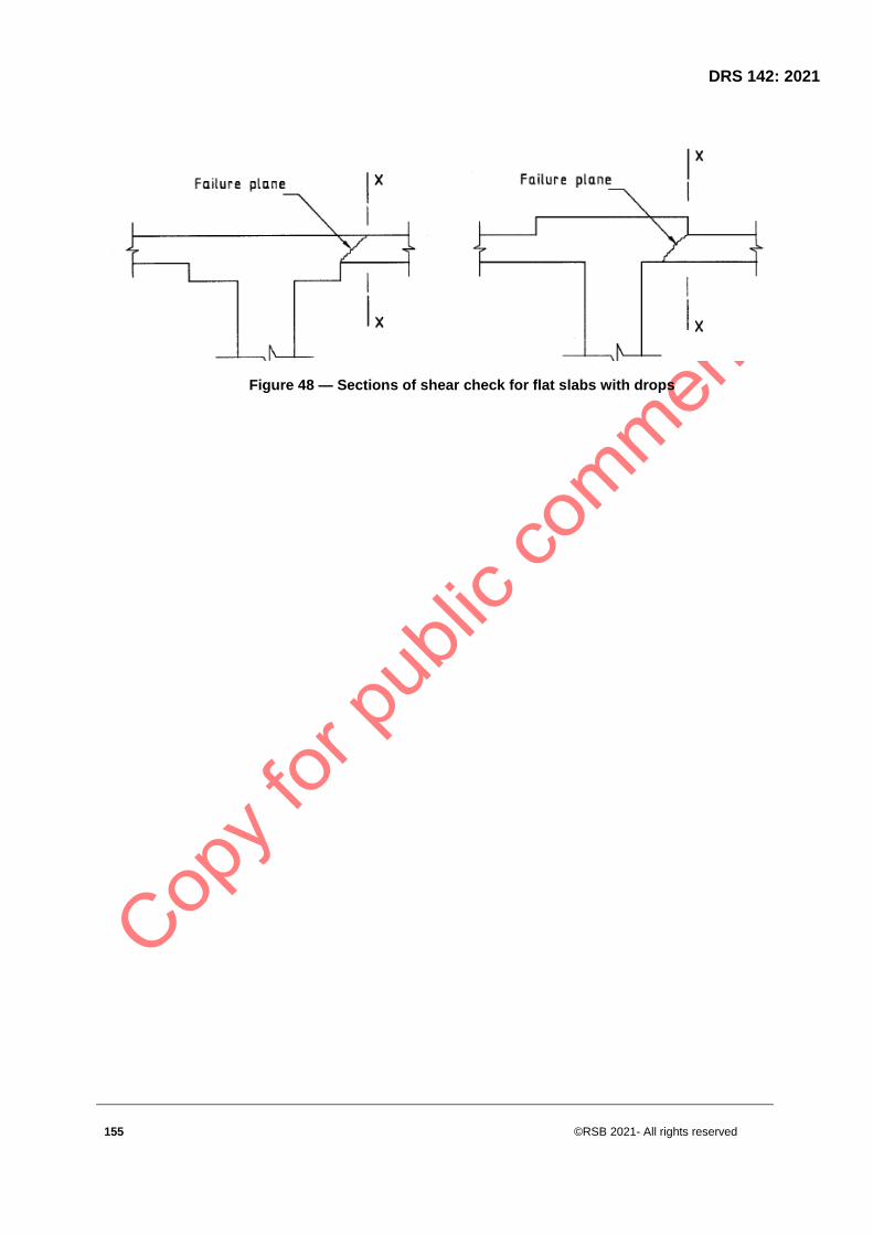
DRS 142: 2021
155 ©RSB 2021- All rights reserved
Figure 48 — Sections of shear check for flat slabs with drops

©RSB 2021 - All rights reserved 156
Figure 49 — Shear at slab internal column connection

DRS 142: 2021
157 ©RSB 2021- All rights reserved
10.7.2.2 Design effective shear force at slab/internal column connection
10.7.2.2. 1 In the case of structures in which stability is provided by shear walls or other bracing designed to resist lateral forces, and where the ratio between adjacent spans does not exceed 1.25, the design effective shear force at the perimeter may be calculated on the assumption that the maximum design load is applied to all panels adjacent to the column under consideration. It will be satisfactory then to take a value of:
Veff = 1.15Vt
where:
Veff is the design effective shear including allowance for moment transfer; and
Vt is the design shear transferred to column (see figure 49).
10.7.2.2. 2 In other cases, i.e. braced frames where the ratio between adjacent spans exceeds 1,25, or in the case of an unbraced frame, the shear force should be calculated as the greater of the following:
or (10.11)
Veff = 1,15Vt
where:
Veff is as in 10.7.2.2.1;
Vt is the design shear for a particular loading arrangement transferred to column (see Figure 49);
Mt is the sum of design moments in column above and below slab for a particular loading arrangement (see 10.7.5.1 and 10.7.5.2); and
x is the length of side of perimeter considered parallel to axis of bending.
10.7.2.2. 3 Equation (10.11) should be used independently for the moments and shear forces about both axes of the column and the design checked for the worst case.
NOTE Mt may be reduced by 30 % where the equivalent frame method has been used and analysis has been based
on pattern loads.
10.7.2.3 Design effective shear force at other slab column connections
10.7.2.3.1 At corner columns and at edge columns that are bent at right angles to the edge, the design effective shear force may be calculated from Veff = 1.25 Vt, where Vt is the design shear force transferred to the column (see Figure 49).
10.7.2.3.2 For edge columns that are bent in a direction parallel to the edge and where the structure has approximately equal spans, the shear force may be calculated from:

©RSB 2021 - All rights reserved 158
Veff = 1.40 Vt
where Veff and Vt are as in 11.7.2.2.
10.7.2.3.3 For other cases of edge columns that are bent in a direction parallel to the edge, the design effective shear should be calculated from the following:
where:
Veff, Vt, Mt and x are as in equation (10.11).
NOTE Mt may be reduced by 30 % where the equivalent frame method has been used and analysis has been based on pattern loads.
10.7.2.4 Maximum design shear stress at the column face
The maximum design shear stress at the column face should not exceed the lesser of 0.8 or 5.0 MPa,
when assessed by means of equation (10.8) or (10.9), as appropriate, on a perimeter equal to the perimeter of the column or column head (this includes an allowance for γm of 1.40).
10.7.2.5 Shear under concentrated loads
The provisions given in 10.6.5.1 for shear stresses in solid slabs under concentrated load should be followed.
10.7.3 Deflection of panels
For slabs with drops of total width in both directions equal to at least one-third of the respective spans, follow the provisions given in 10.6.6 in other cases, multiply the span/effective depth ratios obtained from 10.5.8.2 by 0.9.
10.7.4 Crack control in panels
In general, compliance with the reinforcement spacing rules given in the clause of spacing of reinforcement for slabs will be an acceptable method of controlling flexural cracking in panels but, in certain cases, advantage may be gained from calculating crack widths and comparing them with the required values.
10.7.5 Analysis and design of flat slab structures
10.7.5.1 Analysis of structure: continuous frame method
10.7.5.1.1 The structure may be analysed as given below.
a) the structure may be divided longitudinally and transversely into frames consisting of columns and strips of slab. The width of slab used to define the effective stiffness of the slab may, for vertical loads,

DRS 142: 2021
159 ©RSB 2021- All rights reserved
be taken as the distance between the centres of the panels, and for horizontal loads it will be half this value.
b) the torsional flexibility of the connection of the slab to the column may be taken into account.
c) when the relative stiffness of the slabs and columns is being calculated, the gross cross-section of the concrete alone should be considered. In the case of a recessed or coffered slab that is made solid in the region of the columns, the stiffening effect may be ignored, provided that the solid part of the slab does not extend more than 0.15l into the span, measured from the centre-line of the columns.
10.7.5.1.2 The following arrangement of loads should be considered:
a) all spans loaded with total ultimate load (1.4Gk+ 1,.6Qk);
b) all spans loaded with ultimate self-weight load (1.4Gk) and even spans loaded with ultimate imposed load (1.6Qk); and
c) all spans loaded with ultimate self-weight load (1.4Gk) and odd spans loaded with ultimate imposed load (1.6Qk).
10.7.5.1.3 The following limitation of negative design moments should be considered:
a) Negative moments exceeding those at a distance hc /2 from the centre-line of the column may be ignored, provided that the sum of the maximum positive design moment and the average of the negative design moments in any one span of the slab for the whole panel width is at least:
b) When the above condition is not satisfied, increase the negative moments by the difference between the two values under comparison.
10.7.5.2 Analysis of structure: simplified method
10.7.5.2.1 In addition to the methods given in 10.7.5.1, the simplified method of determining moments may be used for flat slab structures in which lateral stability does not depend on slab/column connections.
10.7.5.2.2 Table 24 may be used if the following conditions are met:
a) the design is based on a single-load case of all spans loaded with the maximum design ultimate load, i.e. the conditions as in the clause of simplification of load arrangement are satisfied;
b) there are at least three rows of panels of approximately equal span in the direction under consideration
c) the column stiffness EI/l of the columns is not less than the EI / l of the slab, or the detailing rules in 10.7.5.4 are followed; and

©RSB 2021 - All rights reserved 160
d) the hogging moments are reduced by 20 % and the sagging moments increased to maintain equilibrium.
Table 24 − Bending moments and shear force coefficients for flat slabs of three or more equal spans
Position Moment Shear Total column moment
Outer support
Column
-0.040Fl*
0.045F 0.04F
Wall
-0.020Fl 0.40F -
Near middle of end span 0.083Fl*) - -
At first interior support 0.063Fl 0.60F 0.022Fl
At middle of interior
supports
0.071Fl - -
At interior supports -0.055Fl 0.50F 0.022Fl
*)The design moments in the edge panel may have to be adjusted to comply with 11.7.5.3.2.
NOTES
1. F is the total design ultimate load on the strip of slab between
adjacent columns (i.e. 1.4Gk + 1.6Qk).
2. l is the effective span = l1 - 2hc /3.
3. The limitations of 11.7.5.1.3 need not be checked.
4. These moments should not be redistributed.
10.7.5.3 Design of flat slabs
10.7.5.3.1 Internal and edge slabs should be designed for the moments obtained as in 10.7.5.1 (with limitations of negative moments taken into account) or as in 10.7.5.2. The moments should be divided between the column strip and the middle strip in the proportions given in table 25.
Table 25 — Distribution of moments in panels of flat slabs designed as continuous frames
Moment Apportionment between column and middle strips expressed as a
percentage of the total negative or positive moment*)
Column strip Middle strip
Negative 75 25
Positive 55 45
*)Where the column strip is taken as equal to the width of the drop, and the middle strip is thereby increased in width to a value
exceeding half the width of the panel, increase the moments to be resisted by the middle strip in proportion to its increased width.
The moments to be resisted by the column strip may then be decreased by an amount such that there is no reduction in either the
total positive or the total negative moments resisted by the column strip and middle strip together.
10.7.5.3.2 Design moments transferable between a slab and the edge or corner columns will only be able to be transferred by a column strip considerably narrower than in the case of an internal column.
10.7.5.3.3 The breadth of this strip be for various typical cases is shown in figure 50. The value of be should never be taken as exceeding the column strip width appropriate for an internal panel. The maximum design moment Mt,max that can be transferred to a column by the appropriate strip may be calculated from the following equation:

DRS 142: 2021
161 ©RSB 2021- All rights reserved
Mt,max = 0.15 be d 2 fcu
where:
be is the breadth of strip;
d is the effective depth for the top reinforcement in the column strip; and
fcu is the characteristic strength of concrete.
10.7.5.3.4 The value of Mt,max should exceed half the design moment obtained from an equivalent frame analysis or it should exceed 70 % of the design moment if a grillage or finite element analysis has been used.
If the value of Mt,max is less than this, the structural arrangements should be changed.
10.7.5.3.5 Where analysis of the structure indicates a design column moment that exceeds Mt,max, the design edge moment in the slab should be reduced to a value not exceeding Mt,max and the positive design moments in the span should be adjusted accordingly. The normal limitations on redistributions and neutral axis depth may be ignored in this case. Moments in excess of Mt,max may only be transferred to a column if an edge beam or strip of slab along the free edge is so reinforced as to carry the extra moment into the column by torsion. In the absence of an edge beam, an appropriate breadth of slab may be assessed using the principles illustrated by figure 50. Alternatively, the method of taking the stiffness of edge columns into account may be used.

©RSB 2021 - All rights reserved 162
Figure 50 — Definition of breadth of effective moment transfer strip be for various typical cases
10.7.5.4 Arrangement of reinforcement
10.7.5.4.1 In general, two-thirds of the amount of reinforcement required to resist the negative design moment in the column strip should be placed in a width equal to half that of the column strip and central to the column.
DRS 142: 2021
163 ©RSB 2021- All rights reserved
10.7.5.4.2 Half the bottom reinforcement should be extended 20 diameters beyond the centre-line of supports.
10.7.5.4.3 When the simplified method given in 10.7.5.2 is used and the columns are relatively flexible (with the stiffness EI/l of smaller order than the stiffness EI/ l of the slab), at least 50 % of the top reinforcement shall extend a distance of 0.3l from the face of supports.
10.7.5.5 Panels with marginal beams or with walls
Where the slab is supported by a marginal beam of depth exceeding 1.5 times the thickness of the slab, or by a wall, ensure that
a) the total load to be carried by the beam or wall comprises the direct load on the beam or wall plus a uniformly distributed load equal to one-quarter of the total load on the panel; and
b) the moments on the half-column strip adjacent to the beam or wall are one-quarter of the moments given in 10.7.5.1 and 10.7.5.2.
10.8 Columns
10.8.1 General
This clause deals with columns for which the larger dimension h is not greater than 4 times the smaller dimension b.
10.8.2 Longitudinal reinforcement
11.8.2.1 Longitudinal bars should have a diameter of not less than ϕ min.
NOTE The recommended value of ϕ min is 12 mm.
10.8.2.2 The total amount of longitudinal reinforcement should not be less than As,min.
NOTE The recommended value of As,min value is given by Expression (10.12)
or 0.002 Ac whichever is the greater ( 10.12)
where:
fyd is the design yield strength of the reinforcement
NEd is the design axial compression force
©RSB 2021 - All rights reserved 164
10.8.2.3 The area of longitudinal reinforcement should not exceed As,max.
NOTE The recommended value of As,max. is 0,04 Ac outside lap locations unless it can be shown that the integrity of
concrete is not affected, and that the full strength is achieved at ULS. This limit should be increased to 0.08 Ac at laps.
10.8.2.4 For columns having a polygonal cross-section, at least one bar should be placed at each corner. The number of longitudinal bars in a circular column should not be less than four.
10.8.3 Transverse reinforcement
10.8.3.1 The diameter of the transverse reinforcement (links, loops or helical spiral reinforcement) should not be less than 6 mm or one quarter of the maximum diameter of the longitudinal bars, whichever is the greater. The diameter of the wires of welded mesh fabric for transverse reinforcement should not be less than 5 mm.
10.8.3.2 The transverse reinforcement should be anchored adequately.
10.8.4 Size and reinforcement of columns
10.8.4.1 The size of a column and the position of the reinforcement in it may be affected by the requirements for durability and fire resistance. Consider these, therefore, before commencing with the design.
10.8.4.2 If a column has a large enough section to withstand the design maximum loads without the addition of reinforcement, it may be designed in the same way as a plain concrete.
10.8.5 Braced and unbraced columns
A column may be considered braced in a given plane if lateral stability to the structure as a whole is provided by walls, bracing or buttressing designed to resist all lateral forces in that plane. It should otherwise be considered unbraced.
10.8.6 Short and slender columns
A column may be considered slender in a particular plane if its slenderness ratio in that plane ( lex/h or ley/b) exceeds 10 for unbraced columns and 17-7M1/M2 for braced columns. It should otherwise be considered short. It is therefore possible that a column may be slender in one plane and short in the other plane and it should be treated accordingly.
10.8.7 Slenderness limits for columns
Generally, the clear height lo should satisfy the following:
a) lo < 60b and b > 0.25h.
If, in any given plane, one end of an unbraced column is unrestrained (e.g. a cantilever column), its clear height lo should satisfy the following:
b) lo < 25b and b > 0.25h.
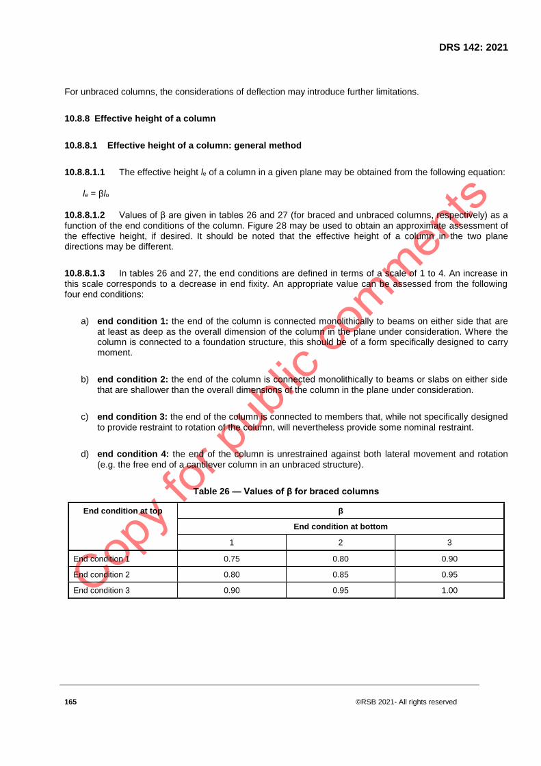
DRS 142: 2021
165 ©RSB 2021- All rights reserved
For unbraced columns, the considerations of deflection may introduce further limitations.
10.8.8 Effective height of a column
10.8.8.1 Effective height of a column: general method
10.8.8.1.1 The effective height le of a column in a given plane may be obtained from the following equation:
le = βlo
10.8.8.1.2 Values of β are given in tables 26 and 27 (for braced and unbraced columns, respectively) as a function of the end conditions of the column. Figure 28 may be used to obtain an approximate assessment of the effective height, if desired. It should be noted that the effective height of a column in the two plane directions may be different.
10.8.8.1.3 In tables 26 and 27, the end conditions are defined in terms of a scale of 1 to 4. An increase in this scale corresponds to a decrease in end fixity. An appropriate value can be assessed from the following four end conditions:
a) end condition 1: the end of the column is connected monolithically to beams on either side that are at least as deep as the overall dimension of the column in the plane under consideration. Where the column is connected to a foundation structure, this should be of a form specifically designed to carry moment.
b) end condition 2: the end of the column is connected monolithically to beams or slabs on either side that are shallower than the overall dimensions of the column in the plane under consideration.
c) end condition 3: the end of the column is connected to members that, while not specifically designed to provide restraint to rotation of the column, will nevertheless provide some nominal restraint.
d) end condition 4: the end of the column is unrestrained against both lateral movement and rotation (e.g. the free end of a cantilever column in an unbraced structure).
Table 26 — Values of β for braced columns
End condition at top β
End condition at bottom
1 2 3
End condition 1 0.75 0.80 0.90
End condition 2 0.80 0.85 0.95
End condition 3 0.90 0.95 1.00

©RSB 2021 - All rights reserved 166
Table 27 — values of β for unbraced columns
End condition at top β
End condition at bottom
1 2 3
End condition 1 1.2 1.3 1.6
End condition 1.3 1.5 1.8
End condition 3 1.6 1.8 -
End condition 2.2 - -
10.8.8.2 Effective height of a column: more rigorous method
10.8.8.2.1 For a framed structure, effective height may be obtained from the following equations:
a) for a braced column, the lesser of
le = lo [0.7 + 0.05 (αc1 + αc2)] < lo and
le = lo (0.85 + 0.05 αc,min) < lo
b) for an unbraced column, the lesser of
le = lo [1.0 + 0.15 (αc1 + αc2)] and
le = lo (2.0 + 0.3 αc,min)
where
lo is the clear height between end restraints;
αc1 is the ratio of sum of column stiffnesses to sum of beam stiffnesses at one end of column;
αc2 is the ratio of sum of column stiffnesses to sum of beam stiffnesses at other end of column; and αc,min is the lesser of αc1 and αc2.
10.8.8.2.2 The stiffness of a member should be obtained by dividing the second moment of area of its concrete section by its actual length, which is the distance centre-to-centre of restraints.
10.8.8.2.3 When αc is being calculated, only elements properly framed into the end of the column in the appropriate plane of bending should be considered. In cases of relative stiffness, the following simplifying assumptions may be made:
(i) flat slab construction: the stiffness of an equivalent beam that has the width and thickness of the slab forming the column strip should be assumed; (For edge columns, see 10.7.5.3.2.)

DRS 142: 2021
167 ©RSB 2021- All rights reserved
(ii) simply supported beams framing into a column: αc may be taken as 10;
(iii) connection between column and base design to resist nominal moment only: αc may be taken as 10;
(iv) connection between column and base design to resist column moment: αc may be taken as 1,0.
10.9 Walls
10.9.1 General
10.9.1.1 This clause refers to reinforced concrete walls with a length to thickness ratio of 4 or more and in which the reinforcement is taken into account in the strength analysis.
10.9.1.2 These elements of construction provide lateral stability to the structure as a whole and need not be designed to support the forces transmitted by lateral supports in addition to the other design loads and forces.
10.9.1.3 The overall stability of a multistorey building should not, in any direction, depend on unbraced walls alone.
10.9.2 Forces in lateral supports
10.9.2.1 A lateral support is an element (a prop, a buttress, a floor, cross-wall or other vertical or horizontal element) able to transmit lateral forces from a braced wall to the principal structural bracing or to the foundations.
10.9.2.2 The forces that lateral supports should be able to transmit are assumed to be equal in magnitude to the sum of the following:
a) the simple static reactions to the sum of the applied maximum design horizontal forces at the point of lateral support; and
b) 2.5 % of the total maximum design vertical load that the wall or column is designed to carry at the point of lateral support.
10.9.3 Resistance of lateral supports to rotation
Resistance of lateral supports to rotation should only be considered to exist in the following cases:
a) where both the lateral support and the braced wall are concrete walls that are adequately detailed to provide bending restraint; or
b) where precast or in-situ concrete floors (irrespective of the direction of span) have a bearing on at least two-thirds of the thickness of the wall, or where there is a connection that provides adequate bending restraint.

©RSB 2021 - All rights reserved 168
10.9.4 Vertical reinforcement
10.9.4.1 The area of the vertical reinforcement should lie between As,vmin and As,vmax.
NOTE 1 The recommended value of As,vmin is 0,002 Ac.
NOTE 2 The recommended value of As,vmax is 0,04 Ac outside lap locations unless it can be shown that the
concrete integrity is not affected and that the full strength is achieved at ULS. This limit may be doubled at laps.
10.9.4.2 Where the minimum area of reinforcement, As,vmin, controls in design, half of this area should be located at each face.
10.9.4.3 The distance between two adjacent vertical bars shall not exceed 3 times the wall thickness or 400 mm whichever is the l.
10.9.5 Horizontal reinforcement
10.9.5.1 Horizontal reinforcement running parallel to the faces of the wall (and to the free edges) should be provided at each surface. It should not be less than As,hmin.
NOTE The recommended of As,hmin is either 25 % of the vertical reinforcement or 0.001 Ac, whichever is greater.
10.9.5.2 The spacing between two adjacent horizontal bars should not be greater than 400 mm.
10.9.6 Transverse reinforcement
10.9.6.1 In any part of a wall where the total area of the vertical reinforcement in the two faces exceeds 0.02 Ac, transverse reinforcement in the form of links should be provided in accordance with the requirements for columns.
10.9.6.2 Where the main reinforcement is placed nearest to the wall faces, transverse reinforcement should also be provided in the form of links with at least of 4 per m2 of wall area.
NOTE Transverse reinforcement need not be provided where welded wire mesh and bars of diameter ϕ ≤ 16 mm are used with concrete cover larger than 2 ϕ ,
10.9.7 Forces and moments in reinforced concrete walls
10.9.7.1 Axial forces
The axial force in a reinforced wall may be calculated on the assumption that the beams and slabs that transmit force into the wall are simply supported.
10.9.7.2 Design transverse moments
10.9.7.2.1 Design transverse moments, where derived from beams or other constructions designed to frame monolithically at right angles into the wall, should be calculated using elastic analysis.

DRS 142: 2021
169 ©RSB 2021- All rights reserved
10.9.7.2.2 When a construction is designed to be simply supported by a wall, the eccentricity may be assessed as for plain walls and the resultant moment calculated. Except for short-braced walls that are loaded almost symmetrically, the moment per unit length in the direction at right angles to a wall should be taken as the greater of 0.05nw x h, or nw x 15 mm,
where:
nw is the axial load per unit length and h is the thickness of the wall.
10.9.7.2.3 In a slender wall, significant additional moments may be induced by lateral deflections of the wall under load. To make appropriate allowance for this, such a wall may be considered a slender column bent about the minor axis except that where a wall is reinforced with only one central layer of reinforcement, the additional moments should be doubled.
10.9.7.3 Design in-plane moments
Moments in the plane of a single wall, due to horizontal forces, can be calculated from statics. When a horizontal force is resisted by several walls, the proportion allocated to each wall should be proportional to its stiffness. When a shear connection is assumed between vertical edges of adjacent walls, an appropriate elastic analysis may be used, provided the shear connection is designed to withstand the design force.
10.9.8 Short reinforced walls
10.9.8.1 Short braced axially loaded reinforced walls
Short braced axially loaded reinforced walls that by the nature of the structure cannot be subjected to significant moments, may be designed in the presence of the nominal eccentricity moment by the following equation:
N < 0.40 fcuAc + 0.67Ascfy
NOTE This includes an allowance for γm.
where:
N is the total design axial load on the wall due to maximum design loads;
Fcu is the characteristic strength of concrete;
Ac is the net cross-sectional area of concrete in wall;
Asc is the area of vertical reinforcement; and
fy is the characteristic strength of compression reinforcement.
©RSB 2021 - All rights reserved 170
10.9.8.2 Walls subjected to transverse moments and to uniformly distributed axial forces
When the only eccentricity of force derives from the transverse moments, the design axial load may be assumed to be distributed uniformly along the length of the wall. The cross-section of the wall should be designed to resist the appropriate design ultimate axial load and transverse moment. The assumptions made in the analysis of beam sections apply.
10.9.8.3 Walls subjected to in-plane moments and to axial forces
The cross-section of the wall should be designed by application of the assumptions given in the clause of moments of resistance at ultimate limit state for beams.
10.9.8.4 Walls subjected to axial forces and to significant transverse and in-plane moments
10.9.8.4.1 The assessment of the effects should comprise three stages, as follows:
a) in-plane moments and axial forces: the distribution of force along the wall is calculated by elastic analysis, assuming no tension in the concrete;
b) transverse moments: the transverse moments are calculated.
10.9.8.4.2 At various points along the wall, effects (a) and (b) above are combined and checked, using the assumptions given in the clause of moments of resistance at ultimate limit state for beams.
10.9.9 Slender reinforced walls
10.9.9.1 Design procedure
10.9.9.1.1 The assessment of the effects should comprise three stages, as follows:
a) in-plane moments and axial forces: the distribution of force along the wall is calculated by elastic analysis, assuming no tension in the concrete ;
b) transverse moments: the transverse moments are calculated
10.9.9.1.2 At various points along the wall, effects (a) and (b) above are combined and checked, using the assumptions given in the clause of design of column section for ULS.
10.9.9.2 Limits of slenderness
The slenderness ratio is the ratio of the effective height of the wall le to its thickness h. The following limitations of the slenderness ratio shall be observed:
a) in the case of a braced wall reinforced as in the clause of area of reinforcement in elements, but less than 1 %, the ratio le/h shall not exceed 40;
b) in the case of a braced wall reinforced as in the clause of area of reinforcement in elements but exceeding 1 %, the ratio le/h shall not exceed 45;
DRS 142: 2021
171 ©RSB 2021- All rights reserved
c) in the case of an unbraced wall reinforced as in the clause of area of reinforcement in elements, the ratio le/h shall not exceed 30.
10.9.9.3 Deflection of reinforced walls
The deflection of a reinforced concrete wall will be within reasonable limits if the preceding provisions are followed and if, in the case of a cantilever shear wall, the total height of the wall does not exceed 12 times its length.
10.9.9.4 Crack control in reinforced walls
Cracks in a reinforced concrete wall will be within reasonable limits if the reinforcement is arranged in two layers and each layer complies with the bar spacing rules given in the appropriate clause.
10.10 Staircases
10.10.1 General
10.10.1.1 Distribution of loading
10.10.1.1.1 Assume the ultimate load to be uniformly distributed over the plan area of the staircase.
10.10.1.1.2 When, however, staircases surrounding open wells include two spans that intersect at right angles, the load on the areas common to both spans may be assumed to be divided equally between the two spans.
10.10.1.1.3 When staircases or landings that span in the direction of the flight are built at least 110 mm into walls along part or all of their length, a 150-mm strip adjacent to the wall may be deducted from the loaded area.
10.10.1.2 Effective width of staircases
10.10.1.2.1 Take the effective width of a staircase without stringer beams as the actual width of the staircase.
10.10.1.2.2 When a staircase is built into a wall along part or all of its span, include two-thirds of the embedded width up to a maximum of 80 mm, in the effective width.
10.10.1.3 Effective span of staircases
10.10.1.3.1 When a staircase without stringer beams is built monolithically at its ends into structural elements spanning at right angles to the span of the staircase, take the effective span as the sum of the clear horizontal distance between the supporting elements plus half the widths of the supporting elements, subject to maximum additions of 900 mm at both ends.
10.10.1.3.2 When a staircase without stringer beams is simply supported, take the effective span as the horizontal distance between the centre-lines of the supports.

©RSB 2021 - All rights reserved 172
10.10.1.3.3 For the purposes of this sub clause, a staircase may be taken to include a section of landing spanning in the same direction and continuous with the stair flight.
10.10.1.4 Depth of section
Take the depth of the section as the minimum thickness perpendicular to the soffit of the staircase.
10.10.2 Design of staircases
10.10.2.1 Loading
Staircases should be designed to support the ultimate design load in accordance with the load arrangements given in the appropriate clause.
10.10.2.2 Strength, deflection and crack control
The provisions given in the clause of beams and solid slabs and for beams and slabs may be used except for the span/effective depth ratio of a staircase without stringer beams, where 11.10.2.3 applies.
10.10.2.3 Permissible span/effective depth ratio for staircases without stringer beams
Provided the stair flight occupies at least 60 % of the span, the ratio calculated in accordance with the clause of Span/effective depth ratio for rectangular beams may be increased by 15 %.
10.11 Foundations
10.11.1 General
This sub clause covers the design of pad footings and pile caps.
10.11.2 Moments and forces in foundations
10.11.2.1 Except where the reactions to the applied design ultimate loads and moments are derived by more accurate methods, e.g. an elastic analysis of a pile group or the application of established principles of soil mechanics, make the following assumptions:
a) when the base is axially loaded, assume the reactions to ultimate design loads to be uniformly distributed per unit area or per pile;
b) when the base is eccentrically loaded, assume the reactions to vary linearly across the base or across the pile system.
10.11.2.2 The critical section for bending moment in the design of an isolated base may be taken at the face of the column or wall.

DRS 142: 2021
173 ©RSB 2021- All rights reserved
10.11.2.3 The design moment on a vertical section passing completely across a base should be taken as the moment due to reactions to all design ultimate loads on one side of this section. No redistribution of moments should be made.
10.11.2.4 When the flexural and shear strengths of sections are being calculated, account should be taken of pockets for precast members unless they are to be subsequently grouted with a cement mortar of compressive strength at least equal to that of the concrete in the base.
10.11.2.5 When the resistance to bending is being calculated, bases may be regarded as beams or solid slabs, as appropriate.
10.11.3 Design of pad footings
10.11.3.1 Design moments and forces
Shall refer to clause 11.11.2.
10.11.4 Distribution of reinforcement
10.11.4.1 The reinforcement considered in this sub clause is that at right angles to the concrete section. The reinforcement required in the shorter cross-section of a rectangular base should be placed evenly across the section. If any reinforcement is required in the longer section of a rectangular base in order to resist the bending moment, it should be distributed as follows:
a) the amount equal to As of reinforcement should be spread over a band centred on the column
or support and of width equal to the dimension of the short side of the base;
where,
As is the total area of reinforcement required and β1 is the ratio of the longer to the shorter side.
b) the remaining reinforcement should be spread evenly over the outer parts of the section.
10.11.4.2 Where there are two or more columns and lc is the greater of half the spacing between them or the distance to the edge of the pad, then the following should be considered:
10.11.4.3 When lc exceeds (3c/4 + 9d/4), where c is the column width and d is the effective depth of a pad footing, two-thirds of the required reinforcement should be concentrated within a zone from the centre-line of the column to a distance 1.5d from the face of the column; otherwise the reinforcement should be uniformly distributed over lc.
10.11.4.1 Shear
10.11.4.1.1 The design shear force is the algebraic sum of all the ultimate vertical loads and reactions acting on one side or outside the periphery of the critical section.
©RSB 2021 - All rights reserved 174
10.11.4.1.2 The shear strength of bases in the vicinity of concentrated loads or reactions is governed by the more severe of the following two conditions:
a) shear along a vertical section that extends across the full width of the base (for pad footings, this section may be considered at 1.5 times the effective depth from the face of the loaded area and the provisions given in the clause of shear stress and shear reinforcement in beams will apply); and
b) punching shear around the loaded area, where the provisions given in the clause of shear stresses in solid slabs under concentrated load will apply.
10.11.4.2 Bond and anchorage
The provisions given in relevant clause for bond, anchorage, bearing, laps, joints, and bends in bars apply to reinforcement in bases.
The critical sections for local bond stress are:
a) the critical sections described in the relevant clause of bond, anchorage, bearing, laps, joints, and bends in bars; and
b) sections at which the depth changes or any reinforcement ends.
10.11.4.3 Limit state of deflection
This limit state may be ignored for bases.
10.11.4.4 Crack control in bases
The provisions given in the relevant clause of maximum distances between bars in tension concerning the maximum distance between bars in tension apply to bases, but reinforcement need not be provided in the side of bases to control cracking.
10.11.5 Design of pile caps
10.11.5.1 General
10.11.5.1.1 Pile caps are designed either by the bending theory or by truss analogy; if the latter is used, the truss should be of triangulated form, with a node at the centre of the loaded area.
10.11.5.1.2 The lower nodes of the truss lie at the intersections of the centre-lines of the piles with the tensile reinforcement.
10.11.5.2 Shear forces
10.11.5.2.1 The design shear strength of a pile cap is normally determined by the shear along a vertical cross-section of the full width of the cap. Critical sections for the shear should be assumed to be located at 20 % of the diameter of the pile inside the face of the pile.

DRS 142: 2021
175 ©RSB 2021- All rights reserved
10.11.5.2.2 The whole of the force from the piles with centres lying outside this line should be considered to be applied outside this line.
10.11.5.3 Design shear resistance
10.11.5.3.1 The design shear resistance of pile caps may be determined in accordance with the clause of shear resistance of solid slabs, subject to the limitations given below.
10.11.5.3.2 Where the spacing of the piles is less than or equal to 3 pile diameters, the enhancement of the shear strength may be applied over the whole of the critical section.
10.11.5.3.3 Where the spacing is greater, the enhancement may only be applied to strips of width equal to 3 pile diameters, centred on each pile. Minimum stirrups are not required in pile caps where v < vc (enhanced if appropriate).
10.12 Considerations affecting design details
10.12.1 Constructional deviations
10.12.1.1 Sizes of elements
When deciding on the nominal overall size of a reinforced concrete element, take account of the principles of dimensional co-ordination. Bear in mind that absolute accuracy exists only in theory and that tolerable degrees of inaccuracy have to be accepted in practice. Specify as large a degree of tolerance as possible, without rendering the finished structure or any part thereof unacceptable for the purpose for which it is intended.
10.12.1.2 Dimensional tolerance
The partial safety factor for loads will, on a design based on nominal dimensions, provide for all normal tolerances. However, when large tolerances are being specified for small highly stressed elements, it may, in exceptional cases, be necessary to base the design on net dimensions after making allowance for the maximum specified tolerance.
10.12.1.3 Tolerance on position of reinforcement
10.12.1.3.1 In all normal cases, the design may be based on the assumption that the reinforcement is in its nominal position. However, when reinforcement is located in relation to more than one face of an element (e.g. a link in a beam in which the nominal cover for all sides is given), the actual concrete cover on one side may be greater and can be derived from consideration of certain other tolerances appropriate to:
a) dimensions and spacing of cover blocks, spacers or chairs or both (including the compressibility of these items and the surfaces they bear on);
b) stiffness, straightness, and accuracy of cutting, bending and fixing of bars or reinforcement cage;
c) accuracy of formwork in both dimension and plan (this includes permanent forms such as blinding or brickwork); and

©RSB 2021 - All rights reserved 176
d) the size of the structural part and the relative size of the bars or reinforcement cage.
10.12.1.3.2 In certain cases where bars or reinforcement cages are positioned accurately on one face of a structural element, this may lead to an accumulation of tolerances affecting the position of highly stressed reinforcement at the opposite face of the element. The consequent possible reduction in effective depth to this reinforcement may exceed the percentage allowed for in the normal value of the partial safety factor for loads. In the design of a particularly critical element, therefore, appropriate adjustment to the effective depth assumed may be necessary.
10.12.1.4 Construction and movement joints
10.12.1.4.1 Construction joints
10.12.1.4.1.1 The number of construction joints should be kept to the necessary minimum. Their exact location should be indicated on a drawing or agreed on with the contractor. Generally, construction joints should be at right angles to the direction of the element.
10.12.1.4.1.2 The concrete at the joint should be bonded with the concrete subsequently placed against it to such degree that the load-bearing capacity of the concrete in the area of the joint is not impaired. If it is necessary for a joint to transfer tensile or shear stresses, the surface of the first pour should be roughened to increase the bond strength and to provide aggregate interlock.
10.12.1.4.2 Movement joints
10.12.1.4.2.1 Movement joints are those specifically designed and provided to allow relative movement of adjacent parts of an element or structure to occur without impairment of the functional integrity of the element or structure. They may also act as connection joints between several parts of an element or structure, or they may be provided solely to permit translocation or rotation or both.
10.12.1.4.2.2 Careful consideration should be given to the location of movement joints and their position should be clearly indicated on the drawings, both for the individual elements and for the structure as a whole.
10.12.1.4.2.3 In general, movement joints in the structure should pass through the whole structure in one plane. If special preparation of the joint faces is required, this should be specified.
10.12.2 Concrete cover to reinforcement
10.12.2.1 Nominal cover is that dimension used in design and indicated on the drawings. Determine the concrete cover to reinforcement by consideration of fire resistance and durability under the envisaged conditions of exposure.
10.12.2.2 Cover is not required to the end of a straight bar in a floor or roof unit when the end of the unit is not exposed to the weather. However, the ends of simply supported beams not directly exposed to the weather may be liable to condensation with the consequent need to protect the reinforcement against corrosion. Regard the following as subject to moderate exposure: roofs, balconies, washed down floors, car parks, or any other construction that, although nominally protected from water, might become moist as a result of deterioration of finishes or for other reasons.
10.12.2.3 Always make the nominal cover at least equal to the diameter of the bar and, in the case of bundles of three or more bars, equal to the diameter of a single bar of equivalent area.

DRS 142: 2021
177 ©RSB 2021- All rights reserved
10.12.2.4 Concrete cover to all reinforcement, including links, should be at least equal to the maximum nominal size of the aggregate.
10.12.2.5 Where a surface treatment (such as bush hammering) cuts into the face of the concrete, add the expected depth of treatment to the nominal cover.
10.12.2.6 Where, owing to its particular situation, an element is required to resist the action of fire for a specified period, the nominal cover may need to be increased or, alternatively, the concrete cover to the main bars may need to be reinforced to prevent premature spalling.
10.12.2.7 Take special care in conditions of extreme exposure or where low density or porous aggregates are used. And take account of possible deviations in reinforcement fitting between two concrete faces
10.12.3 Reinforcement (general considerations)
10.12.3.1 Groups of bars
10.12.3.1.1 Bars may be arranged in pairs in contact or in groups of three-bar or four-bar bundles in contact. Each pair or bundle should be treated as a single bar of equivalent area.
10.12.3.1.2 Terminate bars in a bundle at different points spaced at least 40 times the bar size apart except for bundles that stop at a support. Laps may be made to one bar in a bundle at a time. Never, even at laps, should more than four bars be arranged in contact.
10.12.3.1.3 The designer should not use bundles in an element without links.
10.12.4 Minimum areas of reinforcement in elements
10.12.4.1 Minimum area of main reinforcement
10.12.4.1.1 The minimum percentages of main reinforcement appropriate for various conditions of loading and types of member are given in Table 28.
10.12.4.1.2 Should ensure that the minimum number of longitudinal bars provided in a column is four in rectangular columns and six in circular columns and that the diameter of the bars is at least 12 mm.
10.12.4.1.3 Should ensure that the total cross-sectional area of these bars will be at least 0.4 % of the cross-sectional area of the column.
10.12.4.1.4 A wall should not be regarded as a reinforced concrete wall unless the percentage of vertical reinforcement provided is at least 0.4 % of the gross cross-sectional area. This vertical reinforcement may be in one or two layers.
10.12.4.1.5 For purposes of fire resistance, a wall containing less than 1.0 % of vertical reinforcement is classed as a plain concrete wall.

©RSB 2021 - All rights reserved 178
10.12.4.2 Minimum area of secondary reinforcement
10.12.4.2.1 For a solid concrete suspended slab, the amount of reinforcement provided at right angles to the main reinforcement is given in table 28. The distance between bars of the secondary reinforcement shall not exceed five times the effective depth of the slab.
10.12.4.1.2 Where the main vertical reinforcement in a wall is used to resist compression or to provide horizontal reinforcement, the amount of reinforcement provided, expressed as a percentage of the gross cross-section, shall be at least 0.25 % in the case of high-yield steel or 0.3 % in the case of mild steel. The reinforcement shall be of diameter at least 6 mm or at least one-quarter of the diameter of the vertical bars. It may also be necessary to provide links in the thickness of the wall.
10.12.4.3 Minimum size of bars near side faces of beams of overall depth exceeding 750 mm
In order to control cracking, bars provided near side faces of beams should be of diameter at least, where sb is the bar spacing and b the width of the section at s the point considered (or 500 mm, bb/fy whichever is the smaller). The bars should be distributed at a spacing not exceeding 250 mm near the side faces of the beam and the distribution should be done over a distance of two-thirds of the overall depth of the beam, measured from its tension face.
10.12.4.4 Minimum area of links
10.12.4.4.1 In a beam or column, where part or all of the main reinforcement is required to resist compression, provide links or ties of diameter at least one-quarter of the diameter of the largest compression bar at a maximum spacing of twelve times the diameter of the smallest compression bar.
10.12.4.4.2 So arrange links that every corner bar and alternate bar or group in an outer layer of reinforcement is supported by a link passing round the bar and having an included angle of not more than 135o. Ensure that all other bars or groups within a compression zone are within 150 mm of a restrained bar.
10.12.4.4.3 In the case of circular columns, where the longitudinal reinforcement is located round the periphery of a circle, provide adequate lateral support by using a circular tie that passes round the bars or groups.
10.12.4.4.4 In a wall, where the percentage of vertical reinforcement used to resist compression exceeds 2 %, provide links of diameter at least 6 mm (or at least one-quarter of the diameter of the largest compression bar) throughout the thickness of the wall. Ensure that the spacing of these links does not exceed twice the wall thickness in either the horizontal or the vertical direction and, in the vertical direction, does not exceed 16 times the bar diameter.
10.12.4.4.5 The Designer should ensure that any vertical compression bar not enclosed by a link is within 200 mm of a restrained bar.
Table 28 — Minimum percentage of reinforcement
Situation Definition of percentage Minimum percentage
fy = 250 MPa fy = 450 MPa
Tension reinforcement
Sections subjected mainly
to tension
100 As/ Ac 0.8 0.45

DRS 142: 2021
179 ©RSB 2021- All rights reserved
Section subjected to
flexure
a)Flanged beams, web in
tension:
− bw / b < 0.4
bw ≥ 0.4
b)flanged beams, flange in tension over a continuous
support:
− T-beam
− L-beam
c)rectangular section(in solid slabs, this minimum
should be provided in both
directions)
100As/ bwh
100As/ bwh
100As/ bwh
100As/ bwh
100As/Ac
0.32
0.24
0.48
0.36
0.24
0.18
0.13
0.26
0.20
0.13
Compression
reinforcement
(Where such reinforcement is required for the ultimate
limit state)
General rule
Simplified rules for
particular cases:
Rectangular column or wall
Flanged beam:
− flange in compression
− web in compression
c) rectangular beam
100Asc/Acc
100Asc/Ac
100Asc/bht
100Asc/bwh
100Asc/Ac
0.4
0.4
0,4
0.2
0.2
0.4
0.4
0,4
0.2
0.2
Transverse reinforcement
in flanges of flanged
©RSB 2021 - All rights reserved 180
beams(provided over full effective flange width near
top surface to resist
horizontal shear)
100Ast/ht
0.15
0.15
10.12.4.4.6 In all beams except those of minor structural importance (e.g. lintels) or where the maximum shear stress, calculated in accordance with the clause of Shear resistance of beams, is less than half the recommended value, provide nominal links throughout the span such that for high-yield steel links,
For mild steel links,
where:
Asv is the cross-sectional area of the two legs of a link;
bt is the width of the beam at the level of the tension reinforcement; and
sv is the spacing of links.
10.12.4.4.7 The spacing of links shall not exceed 0.75 times the effective depth of the beam, and the lateral spacing of the individual legs of the links shall not exceed this value. Links shall enclose all tension reinforcement.
10.12.5 Maximum areas of reinforcement in element
10.12.5.1 Beams
Neither the area of tension reinforcement nor the area of compression reinforcement should exceed 4 % of the gross cross-sectional area of the concrete.
10.12.5.2 Columns
The amount of longitudinal reinforcement should not exceed 6 % of the gross cross-sectional area of the column in vertically cast columns or 8 % in horizontally cast columns, except that it may be 10 % at laps in both types of column.
10.12.5.3 Walls
The area of vertical reinforcement should not exceed 4 % (including laps) of the gross cross-sectional area of the concrete.
DRS 142: 2021
181 ©RSB 2021- All rights reserved
10.12.6 Spacing of reinforcement
10.12.6.1 Minimum distances between bars
10.12.6.1.1 When the diameter of a bar exceeds the maximum size of coarse aggregate by more than 5 mm, a spacing smaller than the bar diameter should be avoided. A pair of bars in contact or a bundle of three or four bars in contact should be regarded as a single bar of equivalent area when the spacing is being assessed.
10.12.6.1.2 The spacing of bars should be made suitable for the proper compaction of concrete, and when an internal vibrator is likely to be used, adequate spacing should be provided in the reinforcement to enable the vibrator to be inserted. Minimum reinforcement spacing is best determined by experience or proper work tests, but in the absence of better information, the distances given below may be used.
10.12.6.1.1 Individual bars
Except where bars form part of a pair or bundle, the horizontal distance between bars should be at least (hagg + 5) mm, where hagg is the maximum size of the coarse aggregate. Where there are two or more rows:
a) the gaps between corresponding bars in each row should be vertically in line; and
b) the vertical distance between bars should be at least 2/3hagg.
10.12.6.1.2 Pairs of bars
Bars may be arranged in pairs either touching or closer than in 10.12.6.1.1 in which case:
a) the gaps between corresponding pairs in each row should be vertically in line and of width at least (hagg + 5) mm;
b) when the bars forming the pair are one above the other, the vertical distance between pairs should be at least 2/3hagg;
c) when the bars forming the pair are side by side, the vertical distance between pairs should be at least (hagg + 5) mm.
10.12.6.1.3 Bundled bars
Horizontal and vertical distances between bundles should be at least (hagg + 15) mm and the gaps between the rows or bundles should be vertically in line.
©RSB 2021 - All rights reserved 182
10.12.6.2 Maximum distances between bars in tension
10.12.6.2.1 Beams
10.12.6.2.1.1 The rules given below for beams may apply in normal internal or external conditions of exposure where a crack width limited to 0.3 mm is appropriate, unless the calculations of crack width show that greater spacing is acceptable.
10.12.6.2.1.2 In the application of these rules in the case of bars of mixed sizes, any bar of diameter less than 0.45 times the diameter of the maximum bar in the section should be ignored, except when those near the side faces of beams are being considered.
10.12.6.2.2 Slabs
10.12.6.2.2.1 The clear spacing between main bars should not exceed the lesser of three times the effective depth or 750 mm. In normal internal or external conditions, unless crack widths are checked by direct calculations, the additional rules given below ensure adequate control of cracking.
10.12.6.2.2.2 No additional check is required on bar spacing if:
a) grade 250 steel is used and the slab depth does not exceed 250 mm;
b) grade 450 steel is used and the slab depth does not exceed 200 mm; or
c) the amount of tension reinforcement in a slab, expressed as a percentage of the cross-sectional area (the width of section times the effective depth), is less than 0.3 %.
11 Design and detailing of Precast, composite and plain concrete constructions
11.1 General
11.1.1 Design objectives
This section is concerned with the additional considerations that arise in design and detailing when precast units, including large panels, are incorporated into a structure, or when a structure in its entirety is of precast concrete construction. It also covers the use of plain concrete for walls or where the reinforcement provided is less than the minimum required for reinforced concrete.
This section provides additional rules for plain concrete structures
11.1.2 Limit states design
11.1.2.1 Basis of design
Shall comply with provisions given in RS 112.

DRS 142: 2021
183 ©RSB 2021- All rights reserved
11.1.2.2 Handling stress
11.1.2.2.1 Precast units should be designed to resist, without permanent damage, all stresses induced by handling, storage, transport and erection.
11.1.2.2.2 When necessary, specify the positions of lifting and supporting points. Consultation at the design stage with those responsible for handling is an advantage. Ensure that the design takes into account the effects of both snatch lifting from and placing onto supports.
11.1.2.3 Connections and joints
11.1.2.3.1 The design of connections is of fundamental importance in precast construction and should be carefully considered. The engineer responsible for the overall stability of the structure should ensure the compatibility of the design and details of components. The responsibility for overall stability shall be clearly assigned when some or all of the design and details are not worked out by the engineer.
11.1.2.3.2 Joints to allow for movement due to shrinkage, thermal effects and possible differential settlement of foundations are of as great importance in precast as in in-situ construction. Determine the number and spacing of such joints at an early stage in the design. In the design of beam and slab ends on corbels and nibs, take particular care to provide overlap and anchorage of all reinforcement adjacent to the contact faces, taking constructional tolerances into consideration.
11.1.2.4 Stability
11.1.2.4.1 The provisions regarding stability for other concrete elements apply also to precast, composite and plain concrete construction except that, in structures of five storeys or more, supported by plain concrete walls, it will be necessary to ensure that the area of effective vertical ties from foundation to roof level is at least 0.2 % of the cross-sectional area of the walls.
11.1.2.4.2 The minimum dimension of any in-situ concrete section in which tie bars are provided should be not less than the sum of the bar size (or twice the bar size at laps) plus twice the maximum aggregate size plus 10 mm.
11.1.2.4.3 The tie should be able to transmit the forces from the reinforcement in the precast units and to develop the required strength at all lapped joints. If enclosing links are used, the ultimate tensile resistance of the links should be not less than the ultimate tension in the tie.
11.1.2.4.4 Ensure that column and wall ties do not, for their anchorage at either end, rely solely on the bond of a straight plain bar. So bend or so hook plain bars as to provide the required anchorage in bearing on sound concrete unless they are welded or mechanically anchored to the main reinforcement in a precast unit.
11.1.2.4.5 As an alternative to providing the vertical ties recommended above for structures of five storeys or more, such structures may be designed in accordance with the provisions given below.
11.1.2.4.6 Any vertical load-bearing element that cannot be allowed to become ineffective, together with its connections, shall be so designed as to withstand a load of 34 kN/m2 applied to it from any direction. Any horizontal element (or any part thereof) that provides lateral support vital to the stability of that vertical load-bearing element shall be so designed, together with its connections, as to withstand a load of 34 kN/m2 applied to it from any direction. Any element or lateral support so designed should also be capable of supporting the reaction from any attached building components also subject to a loading of 34 kN/m2 or such
©RSB 2021 - All rights reserved 184
reaction as might reasonably be transmitted, having regard to the strength of the attached component and the strength of its connection.
11.2 Precast concrete construction
11.2.1 Framed structures and continuous beams
When the continuity of reinforcement or tendons through the connections or the interaction between units (or both) is such that the structure will behave as a frame or as a continuous beam, the analysis, redistribution of moments, and the design and detailing of individual units may all be in accordance with clause of reinforced concrete or prestressed concrete as appropriate.
11.2.2 Slabs
12.2.2.1 When assessing the effect of concentrated loads (including partitions in the direction of span), ensure that the width of slab assumed to contribute to the support of the load does not exceed the width of the loaded area together with the width of three precast units and joints (when there is no topping) or the width of four precast units and joints (where the topping is at least 30 mm thick), unless test results substantiate the use of a wider area. In no case take the width as extending more than 0.25l on either side of the loaded area, where l is the span.
11.2.2.2 Design precast units intended for use in composite constructions as such, but also check or design for the conditions arising during handling, transportation and erection. In a floor or roof construction of hollow blocks supported by precast concrete ribs, pay particular attention to the bearing of blocks on the ribs when no topping is provided.
11.2.3 Continuous concrete nibs
11.2.3.1 Where a continuous nib less than 300 mm deep provides a bearing, as on a boot lintel, design the nib as a short cantilever slab in accordance with the provisions given below.
11.2.3.2 Ensure that the projection of the nib is sufficient to provide an adequate bearing width for the type of unit to be supported. Give the reinforcement in the nib and any reinforcement in the supported unit a minimum nominal overlap in plan of 60 mm.
11.2.3.3 Assume the line of action of the design load to occur at the outer edge of the loaded area, i.e. at the front edge of the nib, or at the beginning of the chamfered edge, or at the outer edge of the bearing pad, as appropriate.
11.2.3.4 Take the maximum design bending moment as the distance from the line of action of the load to the nearest vertical leg of the links in the beam element from which the nib projects, times the load.
11.2.3.5 Provide links in the element from which the nib projects. The links should be capable of transmitting (in addition to any other forces they resist) the load from the nib to the compression zone of the element.
11.2.4 Allowance for construction inaccuracies
The allowance for construction inaccuracies should cover deviations that can occur during the assembling of components, site construction, manufacture and erection, and may be assessed from a statistical analysis of
DRS 142: 2021
185 ©RSB 2021- All rights reserved
measured or predicted deviation. Alternatively, for supported members of span up to 15 m and with average standards of accuracy, the allowance may be taken as the greatest of:
a) 15 mm, or 3 mm per metre of distance between the faces of steel or precast concrete supports
b) 20 mm, or 4 mm per metre of distance between the faces of masonry supports; and
c) 25 mm, or 5 mm per metre of distance between the faces of in-situ concrete supports.
11.2.5 Horizontal forces or rotation at a bearing
11.2.5.1 The presence of horizontal forces at a bearing can reduce the load-carrying capacity of the supporting unit considerably by causing premature splitting or shearing. These forces may be due to creep, shrinkage, and temperature effects, or may result from misalignment, lack of plumb or other causes.
11.2.5.2 When they are likely to be significant, consider these forces in designing and detailing the joints by providing:
a) either sliding bearings or suitable lateral reinforcement in the top of the supporting unit, and
b) continuity reinforcement to tie together the ends of the supported units.
11.2.5.3 Where, owing to large spans or other reasons, large rotations are likely to occur at the end supports of flexural units, use bearings that are capable of accommodating these rotations.
11.2.6 Joints between precast units
11.2.6.1 General
11.2.6.1.1 Design the critical sections of precast units close to joints to resist the worst combinations of shear, axial force and bending caused by the ultimate vertical and horizontal forces. When the design of the units is based on the assumption that the joint between them is not capable of transmitting moment, either design the joint to ensure that this is or take suitable precautions to ensure that if any cracking develops, it will not be unsightly and will not excessively reduce the unit's resistance to shear or axial force.
11.2.6.1.2 Where a space is left between two or more precast units, which is to be filled later with in-situ concrete or mortar, make the space large enough for the filling material to be placed easily and compacted sufficiently to fill the gap without abnormally high standards of workmanship or supervision. The assembly instructions shall specify clearly at what stage during construction the gap should be filled.
11.2.6.1.3 As the majority of joints will incorporate a structural connection, give consideration to this aspect in the design of the joint.
11.2.6.2 Joints transmitting mainly compression
11.2.6.2.1 A joint that transmits mainly compression is most commonly used for horizontal joints between load-bearing walls or columns. Design the joint to resist all the forces and moments implicit in the assumptions made in analysing the structure as a whole and in designing the individual units to be joined. In the absence of

©RSB 2021 - All rights reserved 186
more accurate information derived from a comprehensive programme of suitable tests, the area of concrete to be considered when the strength of the joint in a wall or column is being calculated, should be the greater of:
a) the area of the in-situ concrete, ignoring the area of any intruding floor or beam units (but not more than 90 % of the wall or column area);
b) 75 % of the area of contact between wall or column and joint.
11.2.6.2.2 Consider only those parts of the floor units that are solid over the bearing, and bed the units properly on concrete or mortar of adequate quality.
11.2.6.2.3 Pay particular attention to detailing the joint and joint reinforcement to prevent premature splitting or spalling of the concrete in the ends of the precast units.
11.2.6.2.4 Where a wall or a column is subjected to lateral loads, design the horizontal joints for shear
11.2.6.3 Joints transmitting shear in slabs
11.2.6.3.1 A joint may be assumed to transmit a shear force between panels when, for example, a wall acts as a wind-bracing wall or a floor acts as a wind girder, provided that one of the provisions given below is complied with.
11.2.6.3.2 Floor units transmitting shear in a horizontal plane should be restrained to prevent their moving apart horizontally, and the joints between them should be formed by grouting with a suitable concrete or mortar mix. When the calculated shear stress in the joint under ultimate loads does not exceed 0.23 MPa, no reinforcement need be provided in or across the joint, and the sides of the unit forming the joint may have the normal finish.
11.2.6.3.3 When the sides or ends of the panels or units forming the joints have a finish "as-extruded" and when the shear stress due to ultimate loads does not exceed 0.45 MPa, no reinforcement need be provided in joints that are under compression in all loading conditions.
11.2.6.3.4 The shear stress due to design ultimate loads, calculated on the minimum root area of a castellated joint, should be less than 1.3 MPa. Separation of the units normal to the joint should be prevented either by the provision of steel ties across the ends of the joint or by the provision of a compressive force normal to the joint under all loading conditions. A taper should usually be provided to the projecting keys of a castellated joint to ease the removal of formwork; to limit movements in the joint, ensure that this taper is not excessive.
11.2.6.3.5 When reinforcement is provided to resist the entire shear force due to design ultimate loads, the shear force V should comply with the following equation:
V = 0.6 Fb tan αf
where:
Fb is the lesser of 0.87fy As or the anchorage value of the reinforcement;
As is the minimum area of reinforcement;
DRS 142: 2021
187 ©RSB 2021- All rights reserved
Fy is the characteristic strength of reinforcement; and
αf is the angle of internal friction between faces of joint.
11.2.6.3.6 Tan αf can vary between 0.7 and 1.7 and is best determined by tests. However, for concrete-to-concrete connections, the following values may be assumed:
a) tan αf = 0.7 for a smooth interface, as in untreated concrete;
b) tan αf = 1.4 for a roughened or castellated joint without continuous in-situ strips across the ends of joints; and
c) tan αf = 1.7 for a roughened or castellated joint with continuous in-situ strips across the ends of joints.
It should be able to be demonstrated that resistance to sliding of the joint is provided by other means.
11.3 Structural connections between units
11.3.1 General
11.3.1.1 Structural requirements for connections
11.3.1.1.1 When designing and detailing the connections across joints between precast units, consider the overall stability of the structure, including its stability during construction or after accidental local damage.
11.3.1.1.2 Take the provisions given in 11.1.2.4 into account and, in addition, consider the severe forces and stresses that may be applied to units during the various stages of handling, transportation and erection.
11.3.1.1.3 Tie all units together adequately as soon as they have been placed in their final positions. When prestressed elements are built into supports, restrained creep effects should be considered.
11.3.1.2 Design method
11.3.1.2.1 Design connections in accordance with the generally accepted methods applicable to reinforced Concrete, prestressed concrete or structural steel. Where, by the nature of the construction or material used, such methods are not applicable, prove the efficiency of the connection by appropriate tests
11.3.1.2.2 Deem a design to be satisfactory on the basis of satisfactory results from an appropriate model test coupled with the use of model analysis to predict the behaviour of the actual structure, provided the work has been carried out by engineers with the relevant experience and using suitable equipment.
11.3.1.3 Considerations affecting design details
In addition to ultimate strength requirements and the provisions given in 11.1.2.4 regarding minimum tying together of the structure, consider the provisions given below.

©RSB 2021 - All rights reserved 188
11.3.1.3.1 Protection
So design connections that the standard of protection against weather, fire and corrosion that is required for the remainder of the structure is maintained.
11.3.1.3.2 Appearance
Where connections are to be exposed, so design them that the quality of appearance required for the remainder of the structure can be readily achieved. This may often be better done by emphasizing the connections rather than by attempting to conceal them.
11.3.1.3.3 Manufacture, assembly and erection
During design, consider methods of manufacture, assembly and erection, and give particular attention to the following points:
a) where projecting bars or sections are required, keep them to a minimum and make them as simple as possible; make such projections no longer than is necessary for security;
b) avoid fragile fins and nibs;
c) locate fixing devices of adequate strength in concrete sections;
d) consider the practicability of both casting and assembly;
e) most connections require the introduction of suitable jointing material; in the design, allow sufficient space for such material to ensure that the proper filling of the joint is practicable;
f) it may be desirable to slacken, release or remove levelling devices such as nuts, wedges, etc., that have no load-bearing function in the completed structure; where this is necessary, ensure that the details are such that inspection (to make certain that this has been done) can be carried out without undue difficulty.
11.3.1.4 Site instructions
11.3.1.4.1 General
The strength and stiffness of any connection can be significantly affected by workmanship on site. The diversity of types of joints and their critical role in the strength and stability of the structure place a particular responsibility on the designer to make clear to those responsible for manufacture and erection, those details that are essential to the correct operation of the joint.
11.3.1.4.2 Consider the following points and, where necessary, pass specific instructions to the site:
a) the sequence of forming the joint;
b) critical dimensions, allowing for permitted deviations, e.g. minimum permissible bearing;

DRS 142: 2021
189 ©RSB 2021- All rights reserved
c) critical details, e.g. accurate location of a particular reinforcing bar;
d) the method of correcting possible lack of fit in the joint;
e) the description of the general stability of the structure, with details of any temporary bracing necessary;
f) the extent to which the uncompleted structure may proceed above the completed and matured section;
g) full details of special materials; and
h) the weld sizes, fully specified (where weld symbols are used, ascertain that these are understood on site).
11.3.2 Continuity of reinforcement
11.3.2.1 General requirements
Where continuity of reinforcement is required through the connection, use a jointing method such that the assumptions made in analysing the structure and critical sections are realized. The following methods may be used to achieve continuity of reinforcement:
a) lapping of bars;
b) sleeving;
c) threading of bars;
d) welding; and
e) any other method proven by tests.
11.3.2.2 Lapping of bars
Where straight bars passing through the joint are lapped, the provisions given in the appropriate clause of laps and joints apply. When reinforcement is grouted into a pocket or recess, provide an adequate shear key on the inside of the pocket.
11.3.2.3 Sleeving
11.3.2.3.1 Three principal types of sleeve jointing may be used, provided that the strength and deformation characteristics have been determined by tests in accordance with the second paragraph of 11.3.1.2. The three types are:
a) grout-filled or resin-filled sleeves capable of transmitting both tensile and compressive forces;

©RSB 2021 - All rights reserved 190
b) sleeves that mechanically align the square-sawn ends of two bars to allow the transmission of compressive forces only; and
c) swaged connectors.
11.3.2.3.2 Ensure that the detailed design of the sleeve and the method of manufacture and assembly are such that the ends of the two bars will be accurately aligned into the sleeve. Ensure that the concrete cover provided for the sleeve is at least that specified for normal reinforcement.
11.3.2.4 Threading
11.3.2.4.1 The following methods may be used for jointing threaded bars:
a) the threaded ends of bars may be joined by a coupler having left-hand and right-hand threads; this type of threaded connection requires a high degree of accuracy in manufacture in view of the difficulty of ensuring alignment;
b) one set of bars may be welded to a steel plate, which is drilled to receive the threaded ends of the second set of bars; the second set of bars is fixed to the plate by means of nuts; and
c) threaded anchors may be cast into a precast unit to receive the threaded ends of reinforcement.
11.3.2.4.2 When there is a risk of the threaded connection working loose, e.g. during vibration while in-situ concrete is being cast, use a locking device.
11.3.2.4.3 Restrict the threading of reinforcement to plain round mild steel bars. Where there is difficulty in producing a clean thread at the end of a bar, use steel that is normally specified for black bolts and that has a characteristic strength of 430 MPa.
11.3.2.4.4 Base the structural design of special threaded connections on tests in accordance with 11.3.1.2.
11.3.2.4.5 Where tests have shown the threaded connection to be at least as strong as the parent bar, the strength of the joint may be based on 80 % of the specified characteristic strength of the joined bars in tension and on 100 % of that of bars in compression, divided in each case by the appropriate γm factor.
11.3.2.5 Welding of bars
11.3.2.5.1 The design of welded connections may be done by ensuring that welded joints do not occur at bends in reinforcement. Where possible, stagger joints in parallel bars of the principal tensile reinforcement in the longitudinal direction.
NOTE Joints may be considered staggered if the distance between them is not less than the end anchorage length
for the bar.
11.3.2.5.2 Joints with structural steel inserts generally consist of a steel plate or rolled steel section projecting from the face of a column to support the end of a beam. Design the reinforcement in the ends of the supported beam in accordance with clause of the design of reinforced concrete.

DRS 142: 2021
191 ©RSB 2021- All rights reserved
11.3.2.5.3 Except where the design ensures that the reaction does not act at the end of the steel section, base the design of the supported unit on a span equal to its overall length, including any projecting steel sections. For the design of the supporting unit and its projecting steel section, assume that the reaction is applied at the end of the projecting steel section.
11.3.3 Connections with structural steel inserts
In the design, consider the possibility of vertical splitting under the steel section due to shrinkage effects and localized bearing stresses, e.g. under a narrow steel plate.
11.3.4 Other types of connection
11.3.4.1 Any other type of connection that can be shown to be capable of carrying the ultimate loads acting on it may be used. Amongst those suitable for resisting shear and flexure are those made by prestressing across the joint.
11.3.4.2 Resin adhesives may be used to form joints subjected to compression but may not be used to resist tension or shear. Use them only where they are adequately protected from the effects of fire.
11.4 Composite concrete construction
11.4.1 General
11.4.1.1 The provisions of this sub clause apply to flexural composite elements consisting of precast concrete units acting in conjunction with added concrete where provision has been made for the transfer of horizontal shear at the contact surface. The precast units may be of either reinforced or prestressed concrete. Analyse and design composite concrete structures and elements in accordance with appropriate clauses for the design of reinforced and prestressed concrete.
11.4.1.2 Pay particular attention, in the design of both the components and the composite section, to the effect of the method of construction, on stresses and deflections, and to whether or not propping is to be used.
11.4.1.3 Base the relative stiffnesses of elements on the properties of the concrete, gross or transformed sections, as described in the appropriate clause of analysis of structures.
11.4.1.4 If the concrete strength in the two components of a composite element differs by more than 10 MPa, make allowance for this when stiffness is being assessed.
11.4.1.5 Differential shrinkage of the added concrete and precast concrete units may require consideration in analysing composite elements for the serviceability limit states; differential shrinkage need not be considered for the ultimate limit state.
11.4.1.6 When precast prestressed units, having pre-tensioned tendons, are designed as continuous elements and continuity is obtained with reinforced concrete cast in-situ over the supports, the compressive stresses due to prestress in the ends of the units may be ignored over the transmission length of the tendons when the strength of sections is being assessed.
©RSB 2021 - All rights reserved 192
11.4.2 Shear
11.4.2.1 Carry out the analysis of the resistance of composite sections to vertical shear due to design ultimate loads in accordance with the appropriate clause of Shear resistance of beams for reinforced concrete and for prestressed concrete.
11.4.2.2 However, when in-situ concrete is placed between precast prestressed units and the composite concrete section is used in design, ensure that the principal tensile stress does not exceed 0.24 fcu anywhere in the prestressed units; calculate this stress by making due allowance for the construction sequence and by taking into account only 0.8 of the compressive stress due to prestress at the section under consideration.
11.4.2.3 Calculations for horizontal shear between the two components of a composite section are governed by the ultimate limit state.
11.4.3 Serviceability limit states
11.4.3.1 General
In addition to the provisions given in the appropriate clauses concerning deflection and control of cracking, the design of composite construction will be affected by the provisions of the following subclauses.
11.4.3.2 Compression in the concrete in the case of prestressed precast units
For composite elements comprising prestressed precast units and in-situ concrete, the methods of analysis may be as given in the clause of Ultimate limit state for beams in flexure. However, the compressive stresses in the precast unit at the interface may be increased by not more than 50 % above the value given in Table 29, provided that the ultimate failure of the composite element is due to excessive elongation of the steel.
Table 29 — Compressive stresses fcu in concrete for serviceability limit states
Nature of loading Allowable compressive stresses
Design load in bending 0.33 fcu
In continuous beams and other statically
indeterminate structures, this may be increased to 0.4 fcu
within the range of support moments
Design load in direct
compression
0.25 fcu
11.5 Plain concrete walls
11.5.1 General
11.5.1.1 A plain concrete wall is a vertical load-bearing concrete element whose greatest lateral dimension exceeds four times its least lateral dimension, and one that is assumed to be without reinforcement when its strength is being considered.

DRS 142: 2021
193 ©RSB 2021- All rights reserved
11.4.2.2 Where the greatest lateral dimension is less than four times the thickness, the provisions of this clause may still be applied.
11.4.2.3 The definitions for short, slender, braced or unbraced reinforced concrete walls given in the appropriate clause of reinforced concrete walls also apply to a plain concrete wall.
11.5.2 Structural stability
Refer to 11.5.3 and other sub clauses related to reinforced concrete walls may be applied.
11.5.3 Design of plain concrete walls
11.5.3.1 Axial force
The design ultimate axial force in a plain concrete wall may be calculated on the assumption that the beams and slabs transmitting forces into it are simply supported.
11.5.3.2 Effective height of unbraced plain concrete walls
The effective height le of an unbraced plain concrete wall should be taken as follows:
a) in the case of a wall supporting at its top a roof or floor slab spanning at right angles:
le = 1.5 lo
b) in the case of other walls: le = 2 lo
where,
lo is the clear height of the wall between lateral supports; for gable walls, lo may be measured midway between eaves and ridge.
11.5.3.3 Effective height of braced plain concrete walls
The effective height of braced plain concrete walls should be taken as follows:
a) where the lateral supports provide resistance both to lateral movement and to rotation, le equals three-quarters of the clear distance between lateral supports or twice the distance between a support and a free edge, as appropriate;
NOTE This distance is measured vertically if the lateral supports are horizontal (e.g. floors) or horizontally if
the lateral supports are vertical (e.g. other walls).
b) where the lateral supports provide resistance to lateral movement only, le equals the distance between centres of supports, or two and a half times the distance between a support and a free edge, as appropriate.

©RSB 2021 - All rights reserved 194
11.5.3.4 Limits of slenderness
The slenderness ratio le/h should not exceed 30, whether the wall be braced or unbraced.
11.5.3.5 Minimum transverse eccentricity of forces
Whatever the arrangements of vertical or horizontal forces, the resultant force in every plain concrete wall should be assumed to have a transverse eccentricity of the greater of at least h/20 or 20 mm. In the case of a slender wall, additional eccentricity can arise as a result of deflection under load.
11.5.3.6 Eccentricity in the plane of the wall
11.5.3.6.1 In the case of a single wall in-plane
Eccentricity due to forces may be calculated by statics alone.
11.5.3.6.2 In a case where a horizontal force is resisted by two or more parallel walls
11.5.3.6.2.1 The force should be assumed to be shared between the walls in proportion to their relative stiffnesses, provided the resultant eccentricity in any individual wall does not exceed one-third of the length of that wall.
11.5.3.6.2.2 Where the eccentricity in any individual wall is found to exceed this, the wall stiffness should be as zero and an adjustment made to the forces that are assumed to be carried by the remaining wall(s).
11.5.3.6.3 In the case of a shear connection being assumed between vertical edges of adjacent walls
An appropriate elastic analysis may be made, provided the shear connection is designed to resist the design ultimate forces.
11.5.3.7 Eccentricity at right angles to the wall
11.5.3.7.1 The load transmitted to a wall by a concrete floor or roof may be assumed to act at one-third of the depth of the bearing area from the loaded face. Where there is an in-situ concrete floor on either side of the wall, the common bearing area may be assumed to be shared equally by each floor.
11.5.3.7.2 Loads may be applied to walls at eccentricities exceeding half the thickness of the wall by means of special fittings (e.g. joist hangers), provided that the adequacy of such fittings against local failure is proved by testing or other means.
11.5.3.7.3 The resultant eccentricity of the total load on a braced wall at any level may be calculated on the assumption that, immediately above a lateral support, the resultant eccentricity of all the vertical loads above that level is zero.
DRS 142: 2021
195 ©RSB 2021- All rights reserved
11.5.3.8 In-plane and transverse eccentricity of resultant force on an unbraced wall
At any level, full allowance should be made for the eccentricity of all vertical loads and the overturning moments produced by any lateral forces above that level.
11.5.3.9 Concentrated loads
When loads are purely local (as at beam bearings), they may be assumed to be immediately dispersed, provided that the local design stress under the load does not exceed 0.6fcu for concrete of grade 25 or higher, or 0.5fcu for concrete of a lower grade.
11.5.3.10 Calculation of design load per unit length
The design load per unit length nw should be assessed on the basis of a linear distribution of load along the length of the wall, with no allowance for any tensile strength.
11.5.3.11 Maximum unit axial load for short braced plain walls
The maximum design ultimate axial load per unit length of wall due to ultimate loads, nw, should satisfy the following equation:
nw < 0.3 (h - 2ex) fcu (11.1)
where,
nw is the maximum design axial load per unit length of wall due to design ultimate loads;
h is the thickness of wall;
ex is the resultant eccentricity of load at right angles to plane of wall
fcu is the characteristic strength of concrete.
11.5.3.12 Maximum unit axial load for slender braced plain walls
At every section of a slender braced wall, the maximum design axial load nw should satisfy equation (11.1) and, additionally, the following:
nw < 0.3 (h - 1.2ex - 2ea) fcu (11.12)
where,
nw, h, ex and fcu are as in 11.5.3.11; and
ea is the additional eccentricity due to deflections, which may be taken as le 2/2 500 where le is the effective height of the wall.

©RSB 2021 - All rights reserved 196
11.5.3.13 Maximum unit axial load for unbraced plain walls
The maximum unit axial load at every section of an unbraced plain wall should satisfy the following two conditions:
a) nw < 0.3 (h - 2ex1) fcu
b) nw < 0.3 [h - 2(ex2 + ea)] fcu
where,
nw, h, ea, and fcu are as in 11.5.3.11 and 11.5.3.12;
ex1 is the resultant eccentricity calculated at top of wall ; and
ex2 is the resultant eccentricity calculated at bottom of wall.
11.5.3.14 Shear strength
The design shear resistance of plain walls need not be checked if one of the following conditions is satisfied:
a) the horizontal design shear force is less than one-quarter of the design vertical load; or
b) the horizontal design shear force is less than that required to produce an average design shear stress of 0.45 MPa over the whole wall cross-section.
NOTE For concrete of grades lower than grade 25 and for lightweight aggregate concrete, the figure of 0.30 MPa
should be used instead of 0.45 MPa.
11.5.3.15 Cracking of concrete
Reinforcement may be needed in walls to control cracking due to flexure or thermal and hydration shrinkage. Wherever reinforcement is provided, the quantity should be:
a) for reinforcement of grade 450: at least 0.25 % of the concrete cross-sectional area; and
b) for reinforcement of grade 250: at least 0.30 % of the concrete cross-sectional area.
11.5.3.16 Reinforcement in plain walls for flexure
If, at any level, a length of wall exceeding one-tenth of the total length is subjected to tensile stress resulting from in-plane eccentricity of the resultant force, vertical reinforcement may be necessary to distribute potential cracking. Reinforcement need only be provided in the area of wall found to be in tension under design service loads. It should be arranged in two layers and should comply with the spacing rules given in the appropriate clause.

DRS 142: 2021
197 ©RSB 2021- All rights reserved
11.5.3.17 Reinforcement in plain walls to counteract cracks resulting from shrinkage and temperature
11.5.3.17.1 Plain concrete walls that exceed 2 m in length and are cast in-situ, may have to be reinforced to control cracking arising from shrinkage and temperature effects, including temperature rises caused by the heat of hydration released by the cement. Reinforcement for this purpose should be considered as follows:
a) in an external plain wall directly exposed to the weather, reinforcement should be provided in both horizontal and vertical directions; it should consist of bars of small diameter, relatively closely spaced, with adequate cover near the exposed surface (see also 11.5.3.15);
b) in an internal wall it may only be necessary to provide reinforcement in that part of the wall where junctions with floors and beams occur, in which case it should be equally dispersed between each face (see also11.5.3.15).
11.5.3.17.2 In general, it will not be necessary to provide reinforcement to counteract shrinkage and temperature effects in walls made of no-fines concrete.
11.5.3.18 Reinforcement around openings in plain walls
Nominal reinforcement should be considered.
11.5.3.19 Deflection of plain concrete walls
The deflection in a plain concrete wall will be within acceptable limits if the preceding provisions have been conformed to and if, in the case of a cantilever shear wall, the total height of the wall does not exceed ten times its length.
12 Fire resistance
12.1 General
12.1.1 When a structural concrete element is subjected to fire, it undergoes a gradual reduction in strength and rigidity. For limit state design, therefore, there are three conditions to be considered:
a) retention of structural strength;
b) resistance to penetration of flames; and
c) resistance to heat transmission.
12.1.2 The first criterion is applicable to all structural elements while the other two criteria are applicable to walls and floors, which perform a separating function.
12.1.3 The requirements for fire resistance for various elements in a structure are either checked by a standard test on a specimen or satisfied by suitable choices based on the data given in this clause.

©RSB 2021 - All rights reserved 198
NOTE Standard fire tests are not intended to give information on the use of an element after it has been subjected to
fire.
12.1.4 The following factors influence the fire resistance of concrete structures (some of these factors cannot be taken into account quantitatively):
a) the size and shape of the element;
b) the type of concrete;
c) the type of reinforcement or tendon;
d) the protective concrete cover provided to reinforcement or tendons;
e) the load supported;
f) the conditions of restraint.
12.1.5 Concretes made with siliceous aggregates have a tendency to spall when exposed to high temperatures but this tendency can be reduced by the incorporation of supplementary reinforcement in the concrete cover. Spalling does not generally occur with either calcareous or lightweight aggregates. The insulation properties of concrete made from lightweight aggregates are superior to those of concrete made from siliceous and calcareous aggregates. Other measures that may be taken to prevent spalling from occurring are:
a) a finish of plaster, vermiculite, etc., applied by hand or sprayed;
b) the provision of a false ceiling as a fire barrier; and
c) the use of sacrificial tensile steel.
12.1.6 Concrete, prestressing tendons, and reinforcement show a reduction in strength at high temperatures. At about 400 °C, tendons are likely to lose about 50 % of their strength at ambient temperature and in the case of reinforcement, a similar reduction in strength occurs at about 550 °C.
12.1.7 The fire resistance of structural elements is generally determined when the element is supporting its service load, which is taken as the sum of all the nominal self-weight and imposed loads.
12.1.8 Thermal restraint can be assumed to be provided by the surrounding structure if no gaps or combustible materials exist between the structure and the ends of the floor or beam and if the surrounding structure is capable of withstanding the thermal stresses induced by the heated floor or beam.
12.1.9 Where plaster or sprayed fibre is used as an applied finish to elements, it may be assumed that the thermal insulation provided is at least equivalent to the same thickness of concrete. Such finishes can therefore be used to remedy deficiencies in cover thickness. For selected materials, the following guidance can be given with respect to allowing the use of additional protection not exceeding 25 mm in thickness as a means of providing effective cover to steel reinforcing or prestressing elements.

DRS 142: 2021
199 ©RSB 2021- All rights reserved
12.2 Beams
12.2.1 The fire resistance of a reinforced or prestressed concrete beam depends on the amount of protective cover, consisting of concrete with or without an insulating encasement, provided to the reinforcement or tendons. It is also necessary that the beam have a minimum width to avoid failure of the concrete before the reinforcement or tendons reach the critical temperature. For I-beams, the web thickness bw of a fully exposed beam should be at least 0.5 of the minimum width for the fire resistance of various beams.
12.2.2 The average concrete cover is determined by summing the product of the cross-sectional area of each bar or tendon and the distance from the surface of the bar to the nearest relevant exposed face, and dividing the sum by the total area of these bars or tendons. Only those bars or tendons provided for the purpose of resisting tension due to ultimate loads should be considered in this calculation. When reinforcement is used in combination with tendons, its total area should be used.
12.2.3 In addition, in certain cases where siliceous aggregate concrete is used, it will be necessary to consider the provision of supplementary reinforcement to hold the concrete cover in position.
12.3 Floors
12.3.1 The fire resistance of a floor depends on the minimum thickness of the concrete section and the average concrete cover to the reinforcement in the tensile zone.
12.3.2 Non-combustible screeds or floor finishes may be taken into account in the estimation of the thickness of concrete.
12.3.3 The average concrete cover is determined by summing the product of the cross-sectional area of each bar or tendon and the distance from the surface of the bar to the nearest relevant exposed face, and dividing the sum by the total area of these bars or tendons. Only those bars or tendons provided for the purpose of resisting tension due to ultimate loads should be considered in this calculation.
12.3.4 In addition, in certain cases where siliceous aggregate concrete is used, it will be necessary to consider the provision of supplementary reinforcement to hold the concrete cover in position.
12.3.5 In the absence of adequate test data, low-density concrete floors should be treated as dense concrete floors even though the fire resistance of the former might be expected to be somewhat superior.
12.3.6 In the case of hollow slabs (or beams with filler blocks), the effective thickness d should be obtained by considering the total solid material per unit width te as follows:
where,
h is the actual thickness of slab;
ξ is the proportion of solid material per unit width of slab; and

©RSB 2021 - All rights reserved 200
tf is the thickness of non-combustible finish.
12.4 Additional protection to floors
The fire resistance of any given form of floor construction may be improved by the provision of an insulating finish on the soffit or by a suitable suspended ceiling.
12.5 Columns
12.5.1 The minimum dimension of a column is a determining factor in the fire resistance it can provide.
12.5.2 Supplementary reinforcement shall consist of either a wire fabric not lighter than 0.5 kg/m2 (2 mm diameter wires at centres not exceeding 100 mm) or a continuous arrangement of links at centres not exceeding 200 mm, incorporated in the concrete cover at a distance not exceeding 20 mm from the face.
12.5.3 Columns that are built into fire-resistant walls to their full height are likely to be exposed to fire on one face only.
12.6 Walls
12.6.1 Concrete walls containing at least 1,0 % of vertical reinforcement
12.6.1.1 Concrete cover to the reinforcement should be at least 15 mm for a fire resistance of up to 1 h, and at least 25 mm for a fire resistance for longer periods. Unless shown otherwise by a test, walls containing vertical reinforcement of less than 1.0 % are regarded as plain concrete walls (see 12.6.2) for fire-resistance purposes.
12.6.1.2 Walls exposed to fire on more than one face are to be regarded as columns (see 12.5).
12.6.2 Plain concrete walls
From the limited data available, the fire resistance of plain siliceous aggregate concrete walls can be taken as follows:
a) Concrete, 150 mm thick: 1 h;
b) Concrete, 175 mm thick: 1.5 h.

DRS 142: 2021
201 ©RSB 2021- All rights reserved
Annex A
(normative)
Properties of reinforcement suitable for use with this code of practice
A.1 General
A.1.1 Table A.1 gives the properties of reinforcement suitable for use with this code of practice. The properties are valid for temperatures between -40 ºC and 100 ºC for the reinforcement in the finished structure.
Table A.1 — Properties of reinforcement
NOTE The recommended value for the fatigue stress range with an upper limit of β fyk and for the minimum relative
rib area are given in Table A.2 The recommended value is 0.6.
Table A.2 — Properties of reinforcement

©RSB 2021 - All rights reserved 202
A.1.2 The values of fyk, k and εuk in Table A.1 are characteristic values. The maximum % of test results
falling below the characteristic value is given for each of the characteristic values in the right hand column of Table A.1.
A.1.3 In order to be deemed to comply with the long term quality levels in Table A.1, the following limits on test results should be applied:
a) where all individual test results of a test unit exceed the characteristic value, (or are below the characteristic value in the case the maximum value of fyk or k) the test unit may be assumed to comply;
b) the individual values of yield strength f a nd ε should be greater than the minimum values and less
than the maximum values. In addition, the mean value, M, of a test unit should satisfy the equation
M ≥ Cv + a (A.3)
where:
Cv is the long term characteristic value
a is a coefficient which depends on the parameter considered
NOTE 1 The recommended value for fyk is 10 MPa and for both k and εuk is 0.
NOTE 2 The minimum and maximum values of fyk, k and εuk for use in a Country may be found in its The
recommended values of fyk, k and εuk are given in Table A.3.
Table A.3 — Absolute limits on test results
Performance
characteristics
Minimum value Maximum value
Yield strength fyk 0.97 xminimum Cv 1.03 xmaximum Cv
k 0.98 xminimumCv 1.02 xmaximum Cv
εuk 0.80 xminimum Cv Not applicable
A.2 Strength
The maximum actual yield stress fy,max shall not exceed 1.3fyk.

DRS 142: 2021
203 ©RSB 2021- All rights reserved
Bibliography
[1] RS 142: 2012, Design for concrete structures — Code of practice
[2] Rwanda Building code
[3] Rwanda Urban Planning Code
[4] RS 186 (All parts) Fire safety - code of practice
[5] ISO 13822, Bases for design of structures — Assessment of existing structures
[6] ISO 23469: 2005, Bases for Design of Structures — Seismic Actions for Designing Geotechnical Works
[7] ISO 18408: 2019, Simplified Structural Design for Reinforced Concrete Wall Buildings
[8] ISO 28841: 2013, Guidelines for Simplified Seismic Assessment And Rehabilitation of Concrete Buildings
[9] ISO 19338: 2014, Performance and Assessment Requirements for Design Standards on Structural Concrete


DRS 142: 2021
Price based on 202 pages
©RSB 2021 - All rights reserved