design of diffractive optical elements for augmented/virtual reality … · 2019-11-23 · virtual...
TRANSCRIPT
© 2018 Synopsys, Inc. 1
Simulation and Design Using RSoft Tools
Design of Diffractive Optical Elements for
Augmented/Virtual Reality Applications
© 2018 Synopsys, Inc. 2
Outline
• Introduction
• Synopsys Solutions for AR/VR
• Design Case 1 – Diffractive Slanted Grating
• Design Case 2 – DOE on planar waveguides
• Conclusion
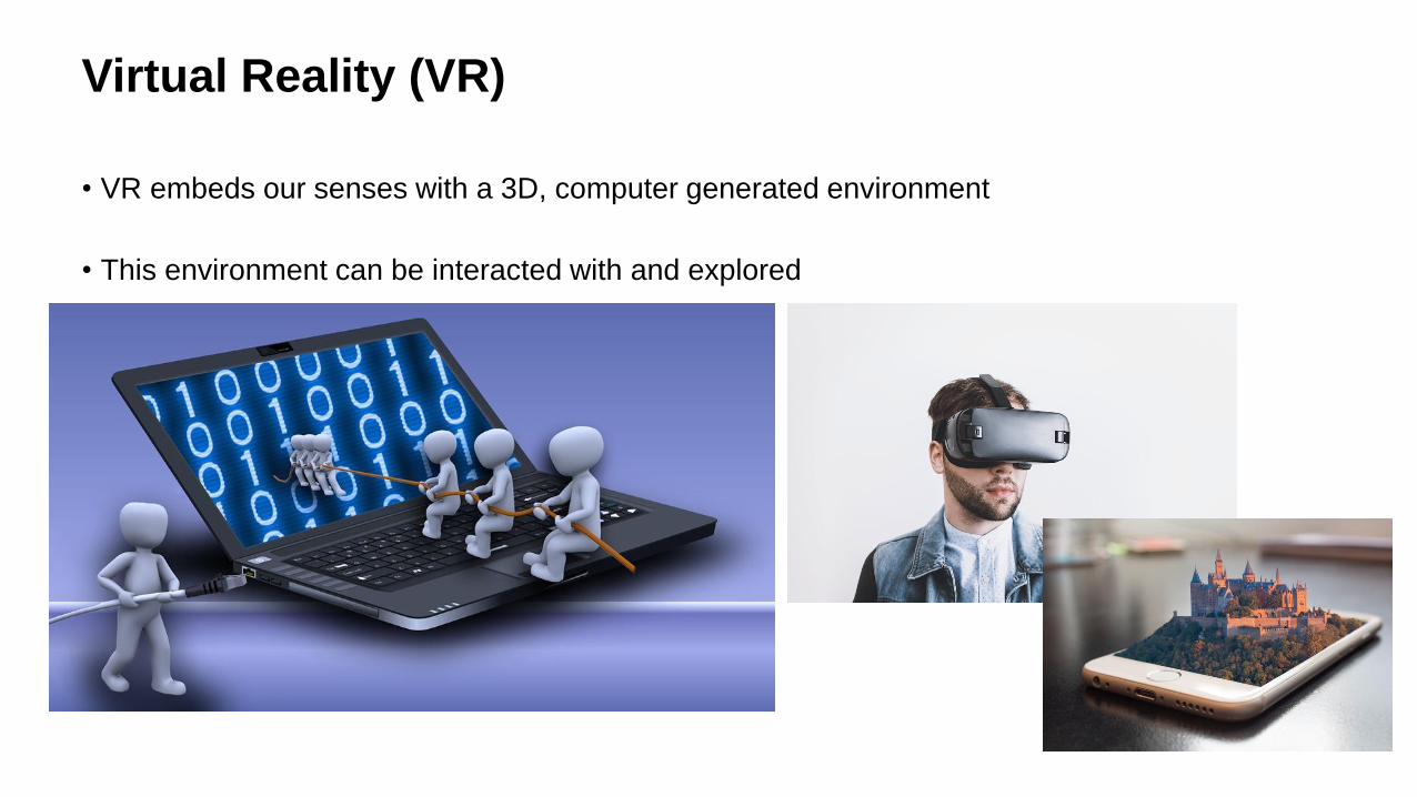
Virtual Reality (VR)
• VR embeds our senses with a 3D, computer generated environment
• This environment can be interacted with and explored

Augmented Reality (AR)
• AR enhances your existing natural environment by overlaying virtual information on top of it
• Both worlds harmoniously exist, providing users a new and (hopefully!) improved natural world
where virtual information can provide assistance to everyday tasks
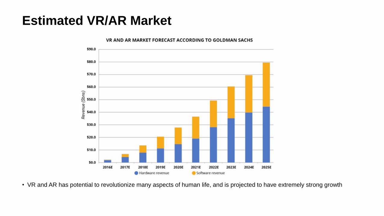
Estimated VR/AR Market
• VR and AR has potential to revolutionize many aspects of human life, and is projected to have extremely strong growth
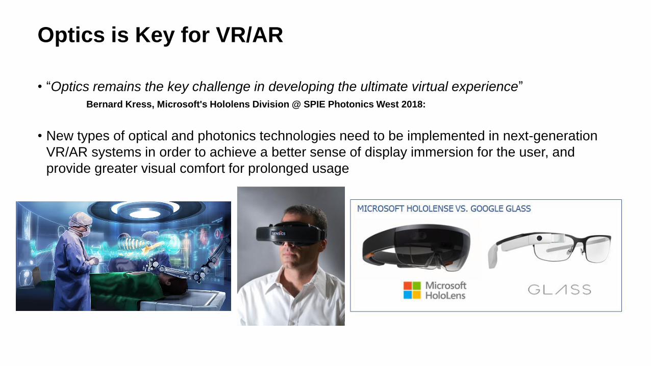
Optics is Key for VR/AR
• “Optics remains the key challenge in developing the ultimate virtual experience”
Bernard Kress, Microsoft's Hololens Division @ SPIE Photonics West 2018:
• New types of optical and photonics technologies need to be implemented in next-generation
VR/AR systems in order to achieve a better sense of display immersion for the user, and
provide greater visual comfort for prolonged usage
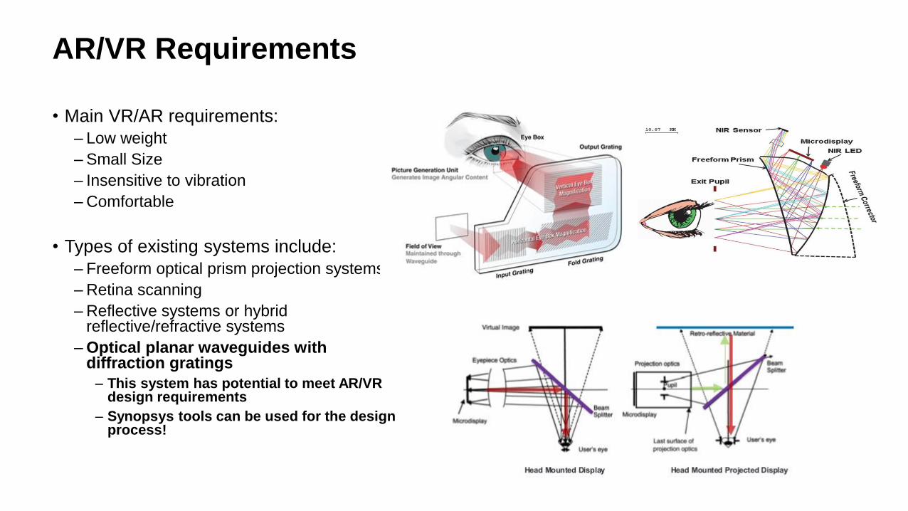
• Main VR/AR requirements:
– Low weight
– Small Size
– Insensitive to vibration
– Comfortable
• Types of existing systems include:
– Freeform optical prism projection systems
– Retina scanning
– Reflective systems or hybrid reflective/refractive systems
– Optical planar waveguides with diffraction gratings
– This system has potential to meet AR/VR design requirements
– Synopsys tools can be used for the design process!
AR/VR Requirements
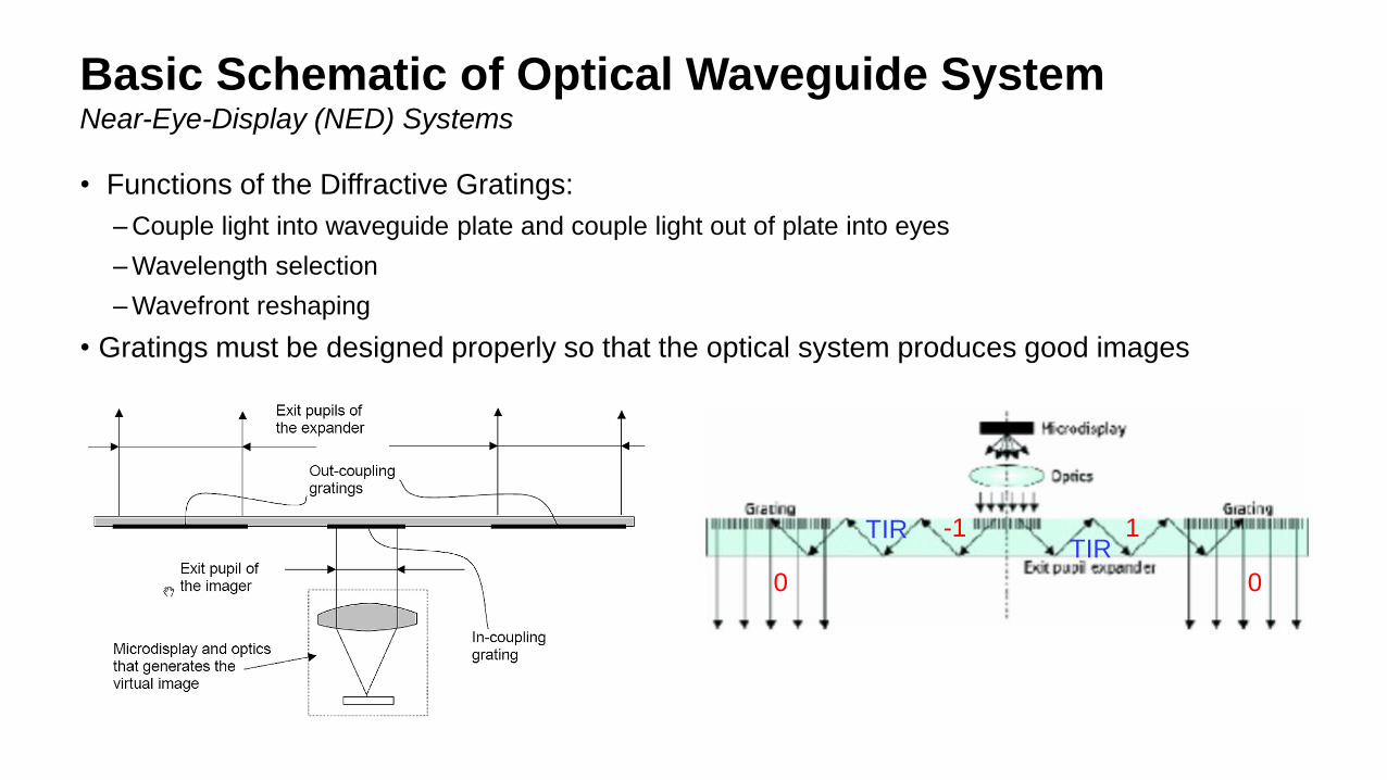
Basic Schematic of Optical Waveguide System
• Functions of the Diffractive Gratings:
– Couple light into waveguide plate and couple light out of plate into eyes
– Wavelength selection
– Wavefront reshaping
• Gratings must be designed properly so that the optical system produces good images
Near-Eye-Display (NED) Systems
-1 1
00
TIRTIR
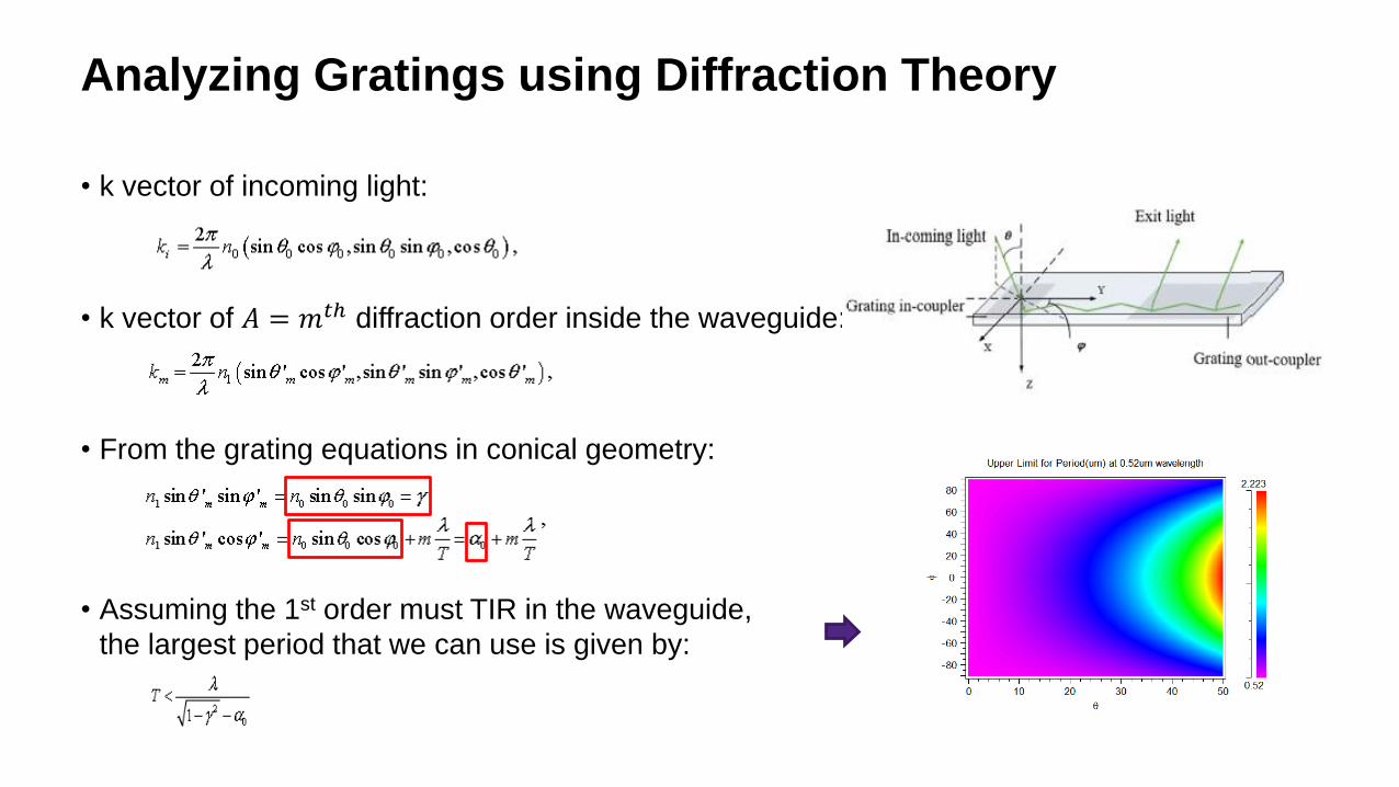
Analyzing Gratings using Diffraction Theory
• k vector of incoming light:
• k vector of 𝐴 = 𝑚𝑡ℎ diffraction order inside the waveguide:
• From the grating equations in conical geometry:
• Assuming the 1st order must TIR in the waveguide,
the largest period that we can use is given by:
Analyzing Gratings using Diffraction Theory
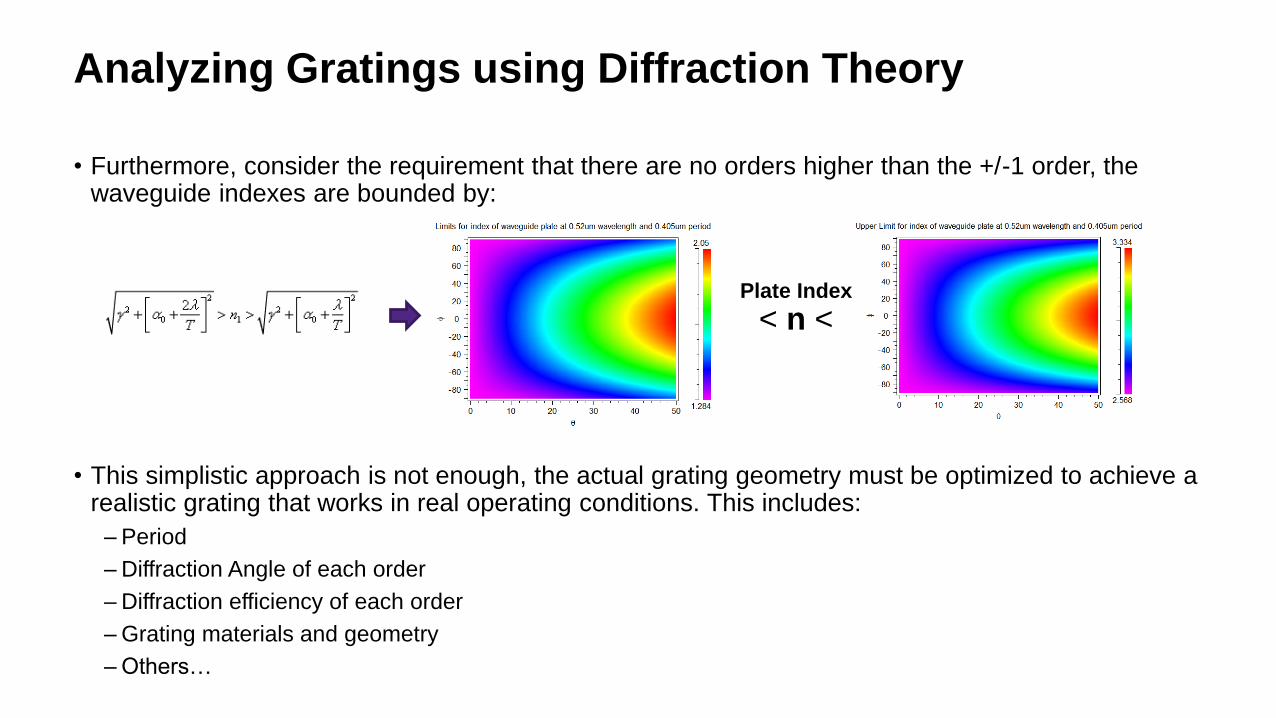
• Furthermore, consider the requirement that there are no orders higher than the +/-1 order, the waveguide indexes are bounded by:
• This simplistic approach is not enough, the actual grating geometry must be optimized to achieve a realistic grating that works in real operating conditions. This includes:
– Period
– Diffraction Angle of each order
– Diffraction efficiency of each order
– Grating materials and geometry
– Others…
< n <Plate Index

© 2018 Synopsys, Inc. 11
Synopsys Solutions for AR/VR
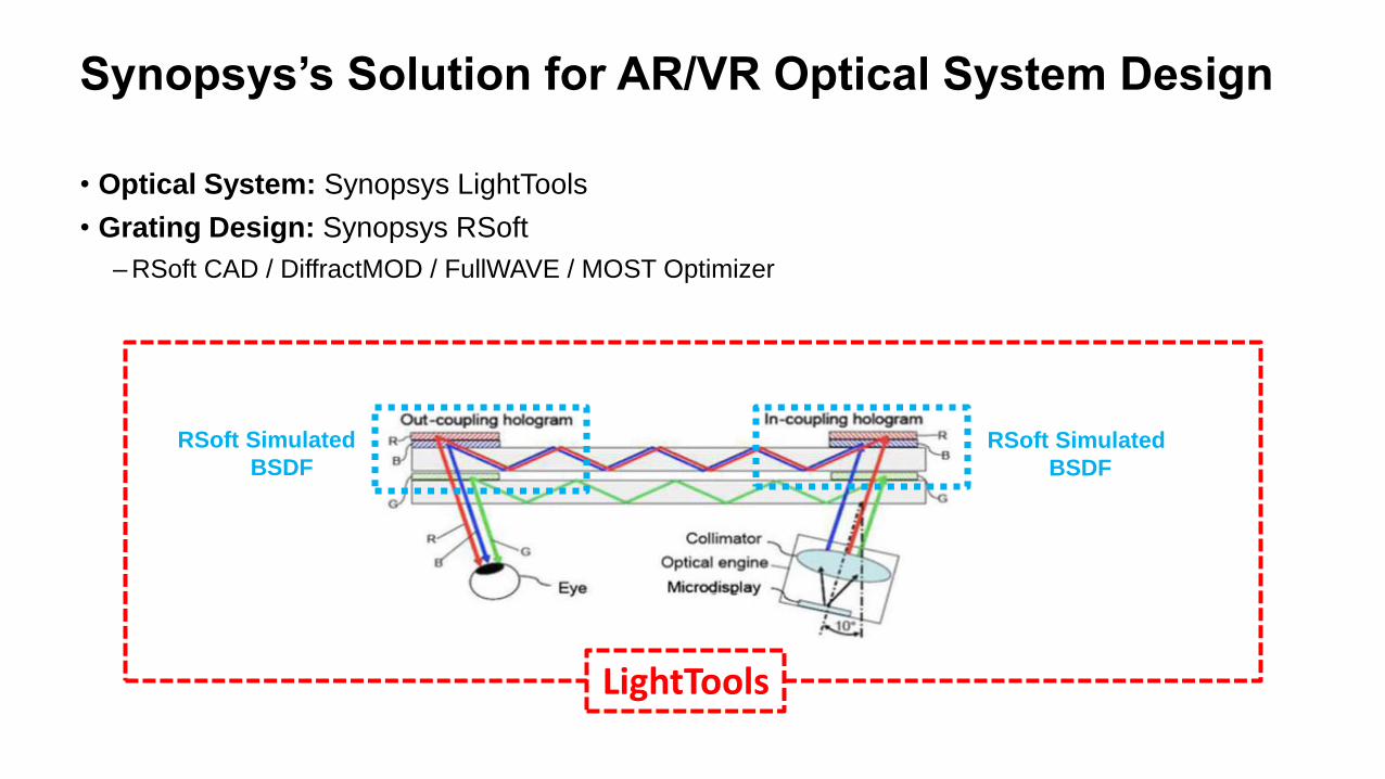
• Optical System: Synopsys LightTools
• Grating Design: Synopsys RSoft
– RSoft CAD / DiffractMOD / FullWAVE / MOST Optimizer
LightTools
RSoft Simulated
BSDF
RSoft Simulated
BSDF
Synopsys’s Solution for AR/VR Optical System Design
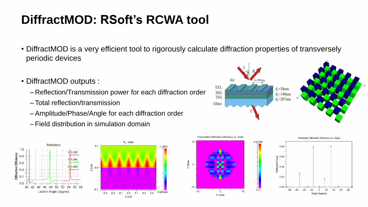
DiffractMOD: RSoft’s RCWA tool
• DiffractMOD is a very efficient tool to rigorously calculate diffraction properties of transversely
periodic devices
• DiffractMOD outputs :
– Reflection/Transmission power for each diffraction order
– Total reflection/transmission
– Amplitude/Phase/Angle for each diffraction order
– Field distribution in simulation domain
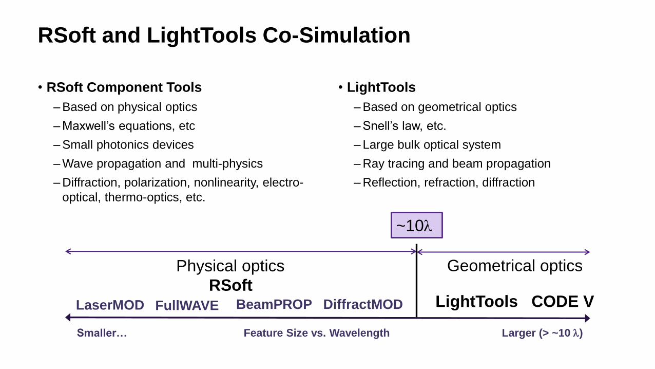
RSoft and LightTools Co-Simulation
• RSoft Component Tools
– Based on physical optics
– Maxwell’s equations, etc
– Small photonics devices
– Wave propagation and multi-physics
– Diffraction, polarization, nonlinearity, electro-
optical, thermo-optics, etc.
• LightTools
– Based on geometrical optics
– Snell’s law, etc.
– Large bulk optical system
– Ray tracing and beam propagation
– Reflection, refraction, diffraction
Feature Size vs. Wavelength Larger (> ~10 l)Smaller…
BeamPROPFullWAVELaserMOD DiffractMOD
Physical optics
~10l
Geometrical optics
RSoftLightTools CODE V
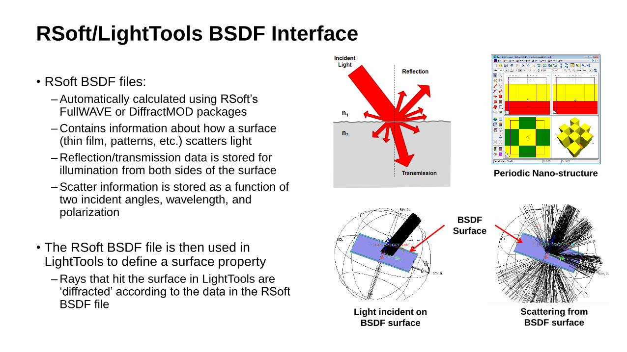
RSoft/LightTools BSDF Interface
• RSoft BSDF files:
– Automatically calculated using RSoft’sFullWAVE or DiffractMOD packages
– Contains information about how a surface (thin film, patterns, etc.) scatters light
– Reflection/transmission data is stored for illumination from both sides of the surface
– Scatter information is stored as a function of two incident angles, wavelength, and polarization
• The RSoft BSDF file is then used in LightTools to define a surface property
– Rays that hit the surface in LightTools are ‘diffracted’ according to the data in the RSoft BSDF file
Periodic Nano-structure
Light incident on
BSDF surface
Scattering from
BSDF surface
BSDF
Surface

© 2018 Synopsys, Inc. 16
Design Case 1 – Diffractive Slanted Grating
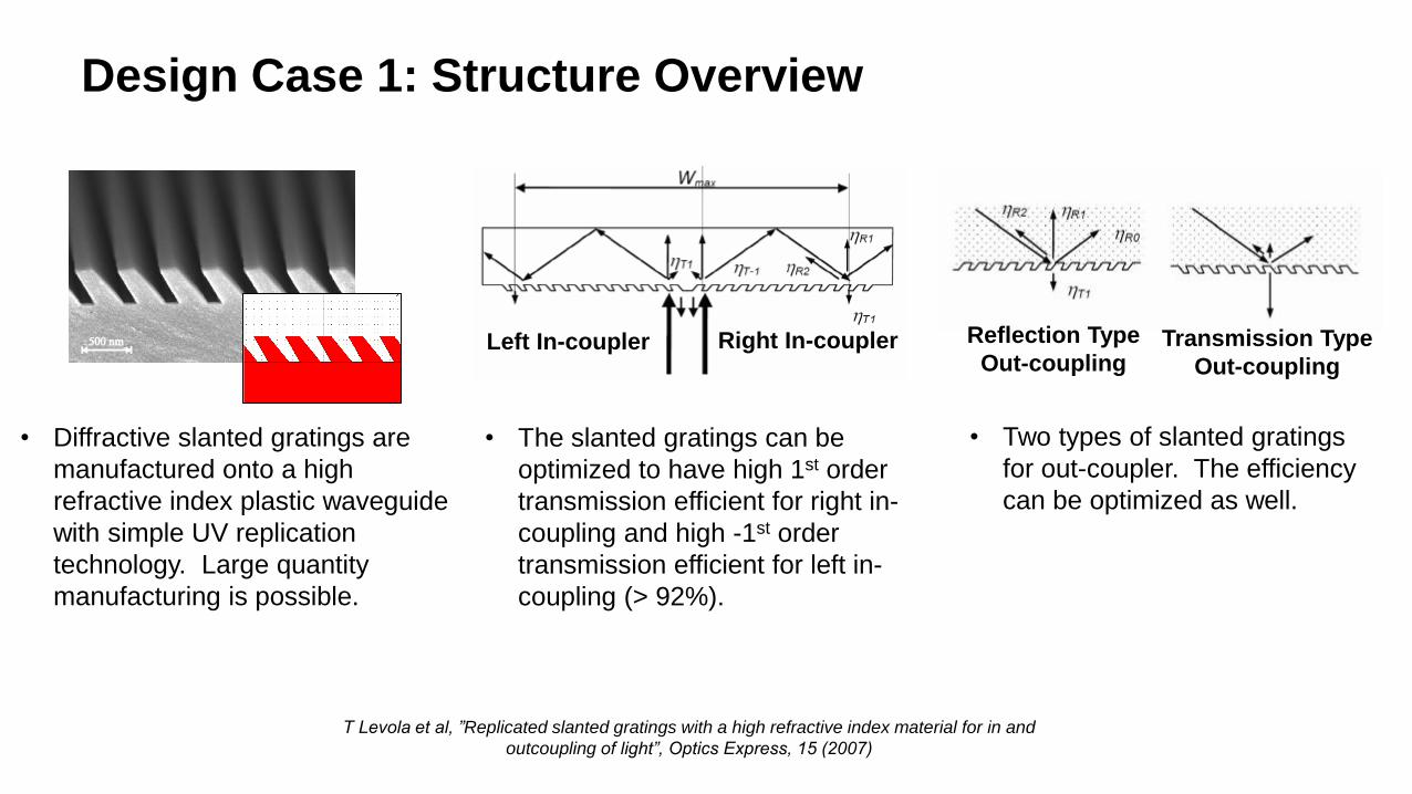
Design Case 1: Structure Overview
T Levola et al, ”Replicated slanted gratings with a high refractive index material for in and
outcoupling of light”, Optics Express, 15 (2007)
Left In-coupler Right In-coupler Reflection Type
Out-couplingTransmission Type
Out-coupling
• Diffractive slanted gratings are
manufactured onto a high
refractive index plastic waveguide
with simple UV replication
technology. Large quantity
manufacturing is possible.
• The slanted gratings can be
optimized to have high 1st order
transmission efficient for right in-
coupling and high -1st order
transmission efficient for left in-
coupling (> 92%).
• Two types of slanted gratings
for out-coupler. The efficiency
can be optimized as well.
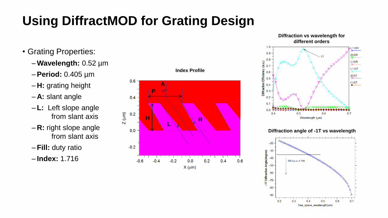
Using DiffractMOD for Grating Design
• Grating Properties:
– Wavelength: 0.52 µm
– Period: 0.405 µm
– H: grating height
– A: slant angle
– L: Left slope angle
from slant axis
– R: right slope angle
from slant axis
– Fill: duty ratio
– Index: 1.716
P
H
A
LR
Index Profile
Diffraction vs wavelength for
different orders
Diffraction angle of -1T vs wavelength
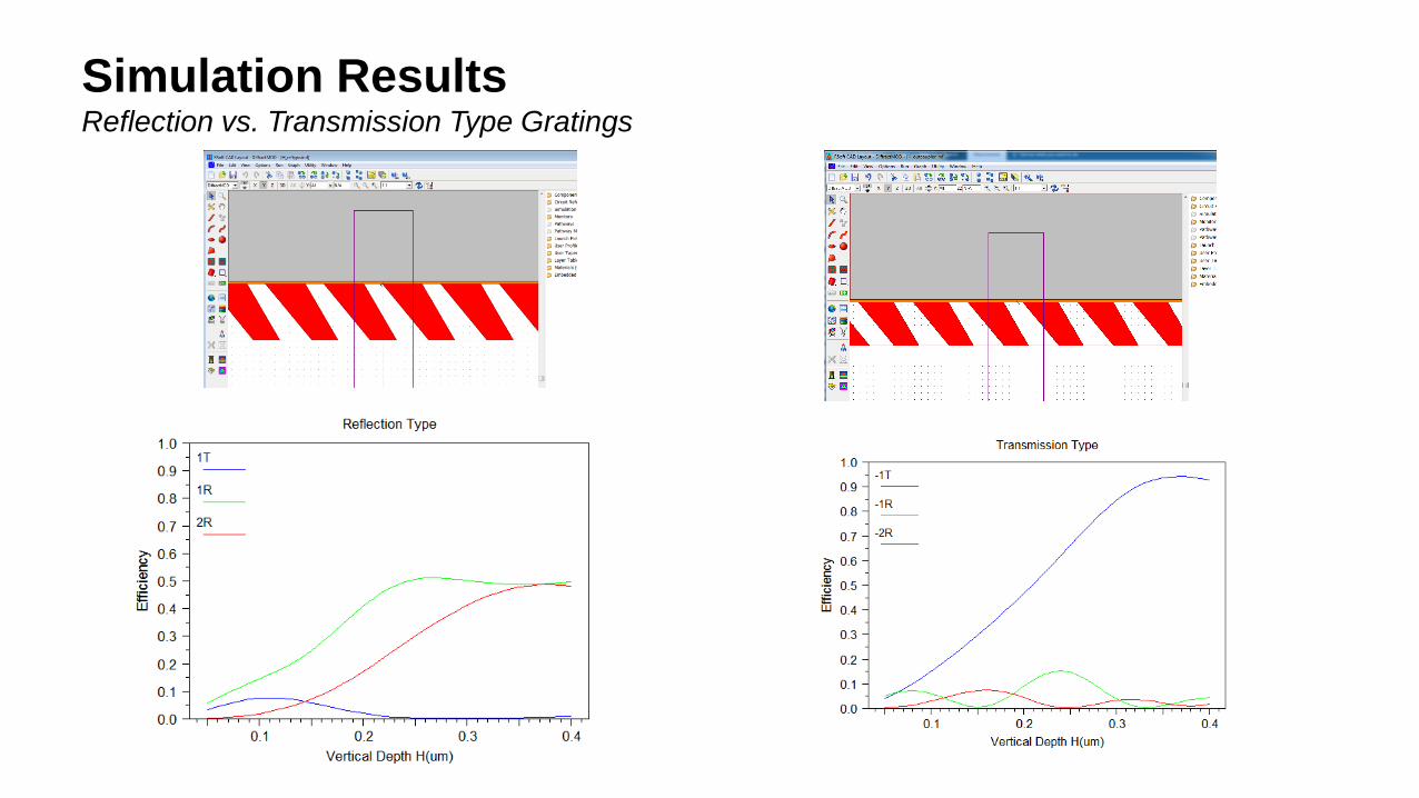
Simulation ResultsReflection vs. Transmission Type Gratings
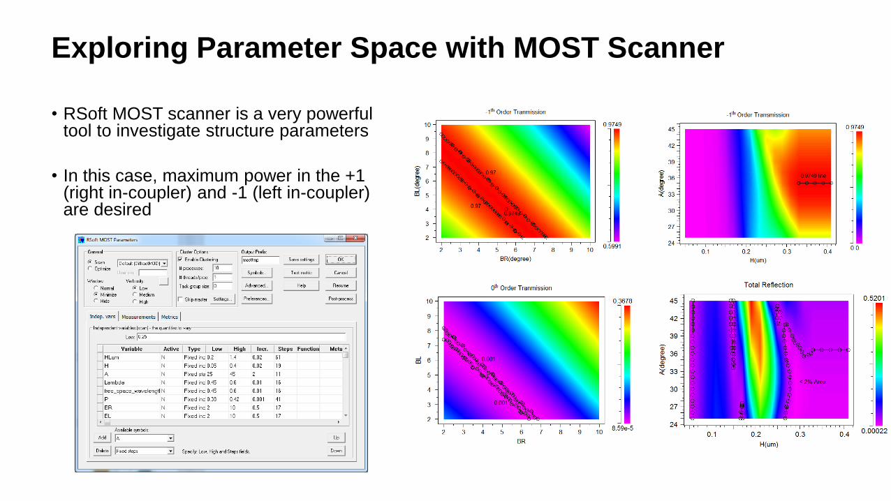
Exploring Parameter Space with MOST Scanner
• RSoft MOST scanner is a very powerful tool to investigate structure parameters
• In this case, maximum power in the +1 (right in-coupler) and -1 (left in-coupler) are desired
Target Function (Python)
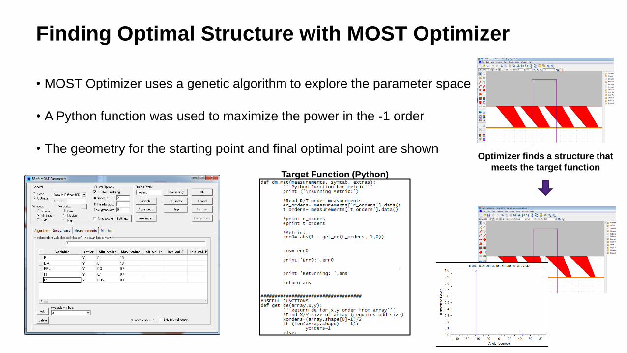
Finding Optimal Structure with MOST Optimizer
• MOST Optimizer uses a genetic algorithm to explore the parameter space
• A Python function was used to maximize the power in the -1 order
• The geometry for the starting point and final optimal point are shownOptimizer finds a structure that
meets the target function
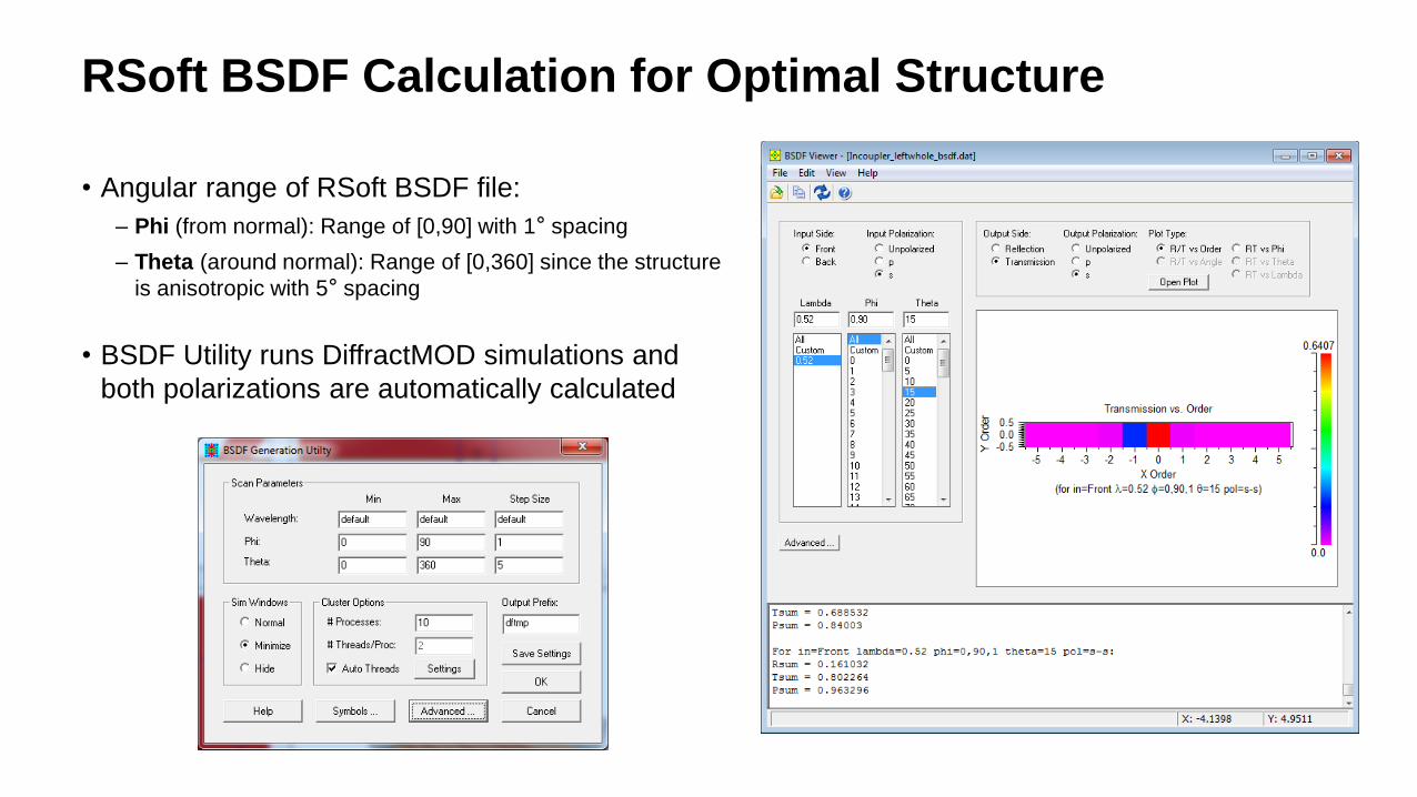
• Angular range of RSoft BSDF file:
– Phi (from normal): Range of [0,90] with 1° spacing
– Theta (around normal): Range of [0,360] since the structure
is anisotropic with 5° spacing
• BSDF Utility runs DiffractMOD simulations and
both polarizations are automatically calculated
RSoft BSDF Calculation for Optimal Structure
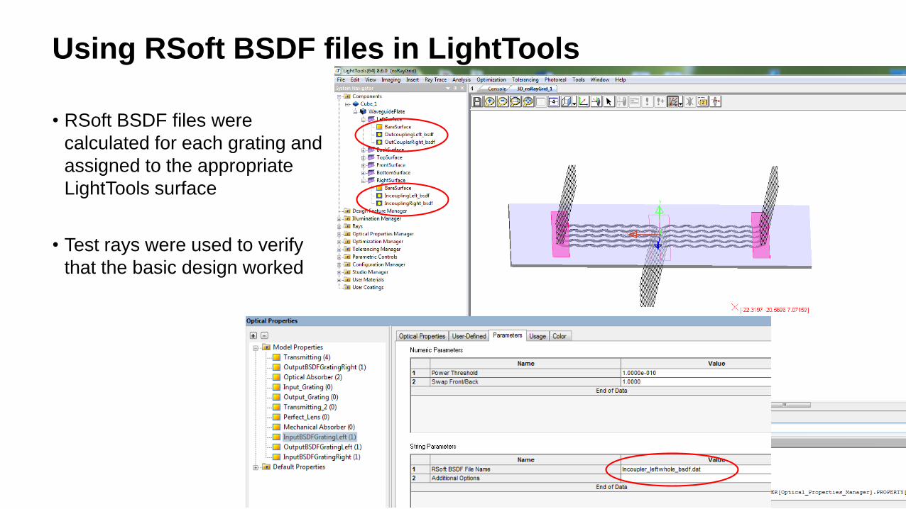
Using RSoft BSDF files in LightTools
• RSoft BSDF files were
calculated for each grating and
assigned to the appropriate
LightTools surface
• Test rays were used to verify
that the basic design workedOutcoupler
Left Incoupler Right Incoupler
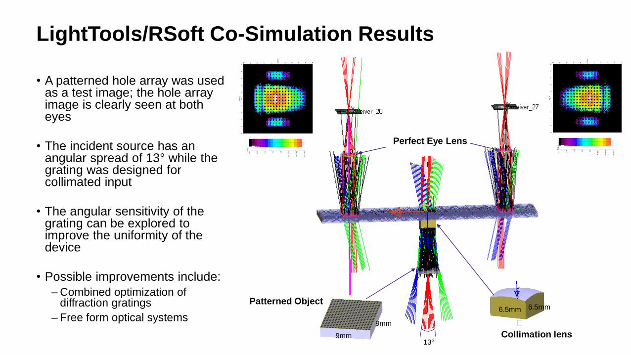
LightTools/RSoft Co-Simulation Results
• A patterned hole array was used as a test image; the hole array image is clearly seen at both eyes
• The incident source has an angular spread of 13° while the grating was designed for collimated input
• The angular sensitivity of the grating can be explored to improve the uniformity of the device
• Possible improvements include:
– Combined optimization of diffraction gratings
– Free form optical systems
Perfect Eye Lens
Collimation lens
Patterned Object
9mm
9mm
13°
6.5mm6.5mm

© 2018 Synopsys, Inc. 25
Design Case 2 – DOE on planar waveguides
By: Tung Yu Su, Cybernet System Taiwan
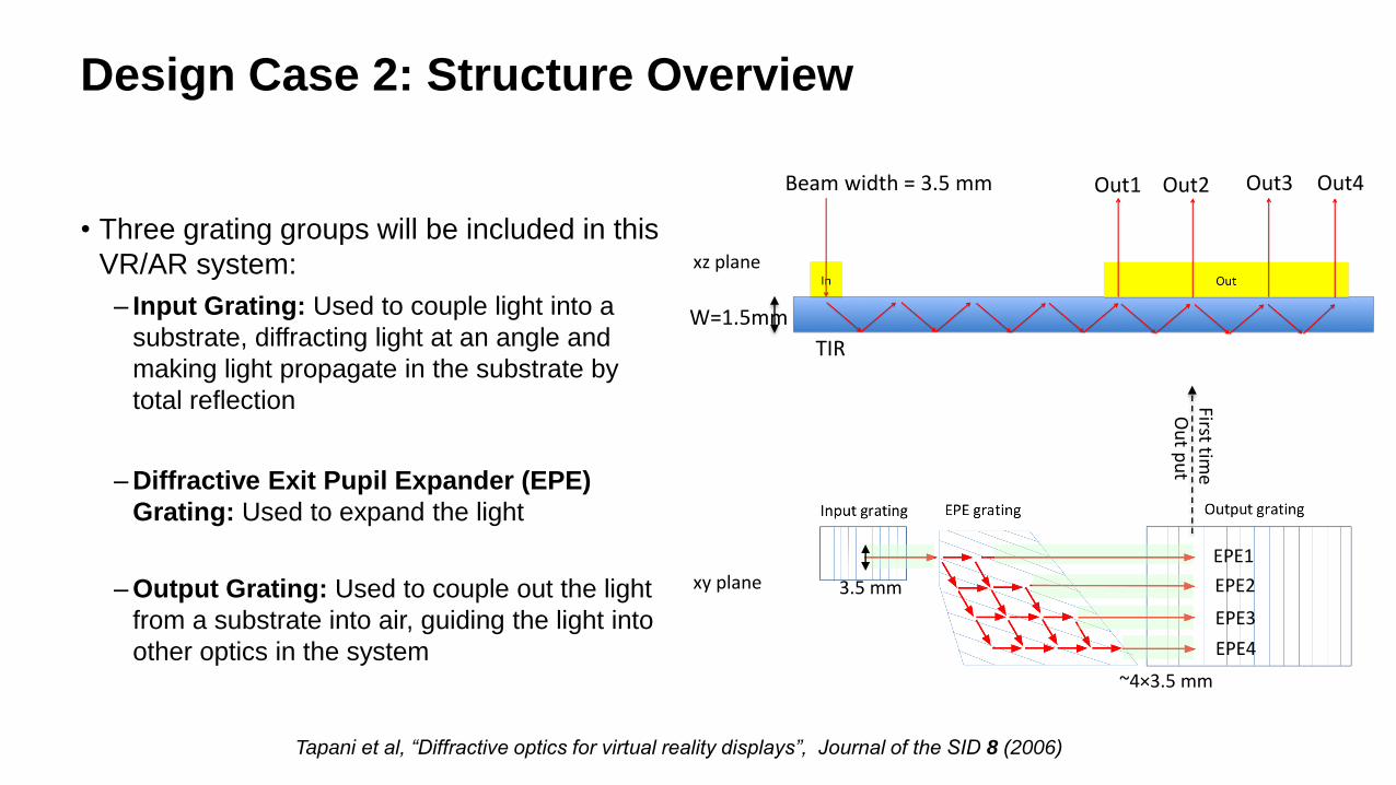
Design Case 2: Structure Overview
• Three grating groups will be included in this
VR/AR system:
– Input Grating: Used to couple light into a
substrate, diffracting light at an angle and
making light propagate in the substrate by
total reflection
– Diffractive Exit Pupil Expander (EPE)
Grating: Used to expand the light
– Output Grating: Used to couple out the light
from a substrate into air, guiding the light into
other optics in the system
Tapani et al, “Diffractive optics for virtual reality displays”, Journal of the SID 8 (2006)
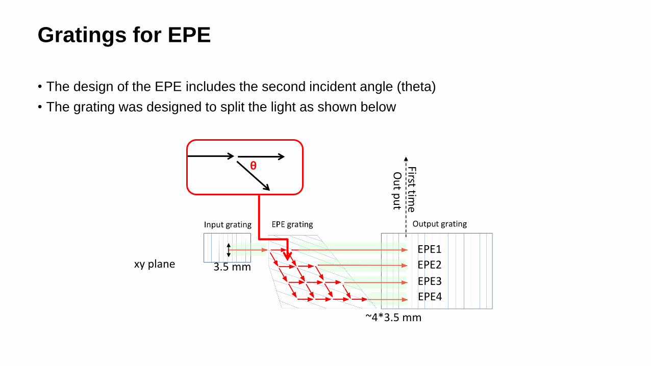
W=1.5mm
Beam width = 3.5 mm Out1 Out2 Out3 Out4
TIR
xy plane
~4×3.5 mm
First time
Ou
t pu
t
3.5 mm
EPE1
EPE2
EPE3
EPE4
xz plane
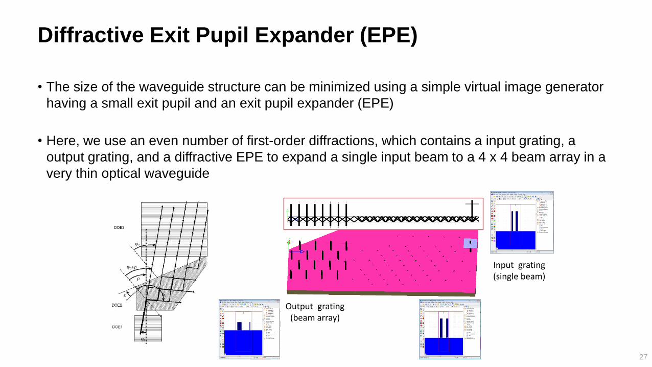
Diffractive Exit Pupil Expander (EPE)
• The size of the waveguide structure can be minimized using a simple virtual image generator
having a small exit pupil and an exit pupil expander (EPE)
• Here, we use an even number of first-order diffractions, which contains a input grating, a
output grating, and a diffractive EPE to expand a single input beam to a 4 x 4 beam array in a
very thin optical waveguide
27
EPE
Output grating(beam array)
Input grating(single beam)
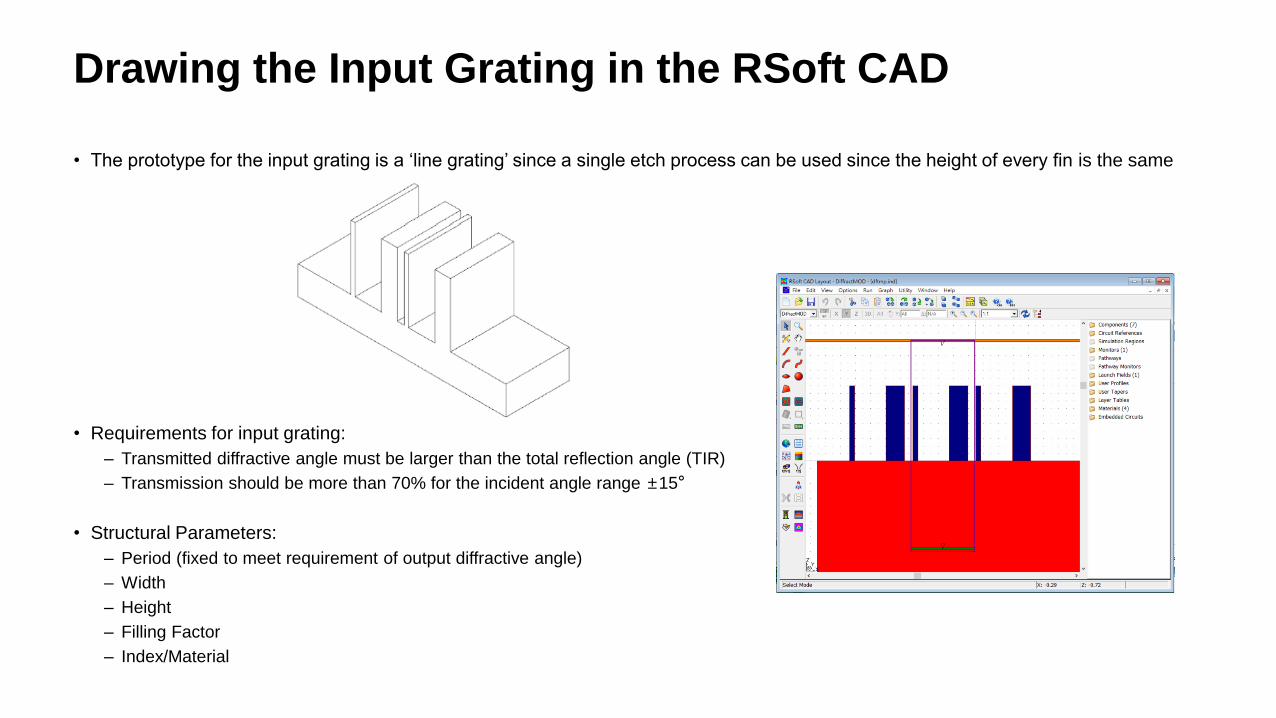
• The prototype for the input grating is a ‘line grating’ since a single etch process can be used since the height of every fin is the same
• Requirements for input grating:
– Transmitted diffractive angle must be larger than the total reflection angle (TIR)
– Transmission should be more than 70% for the incident angle range ±15°
• Structural Parameters:
– Period (fixed to meet requirement of output diffractive angle)
– Width
– Height
– Filling Factor
– Index/Material
Drawing the Input Grating in the RSoft CAD
MOST Optimization
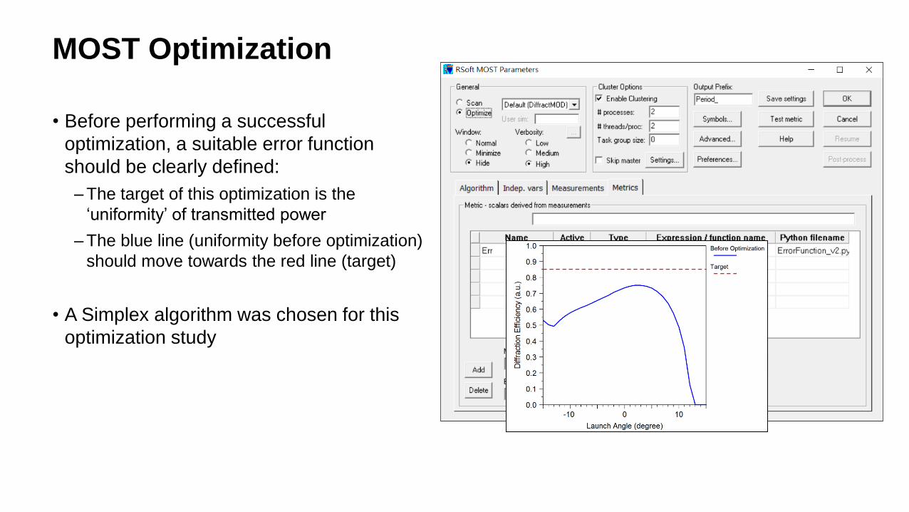
• Before performing a successful
optimization, a suitable error function
should be clearly defined:
– The target of this optimization is the
‘uniformity’ of transmitted power
– The blue line (uniformity before optimization)
should move towards the red line (target)
• A Simplex algorithm was chosen for this
optimization study
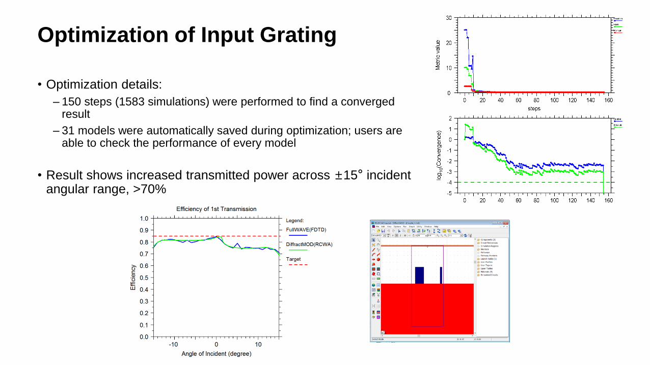
Optimization of Input Grating
• Optimization details:
– 150 steps (1583 simulations) were performed to find a converged result
– 31 models were automatically saved during optimization; users are able to check the performance of every model
• Result shows increased transmitted power across ±15° incident angular range, >70%
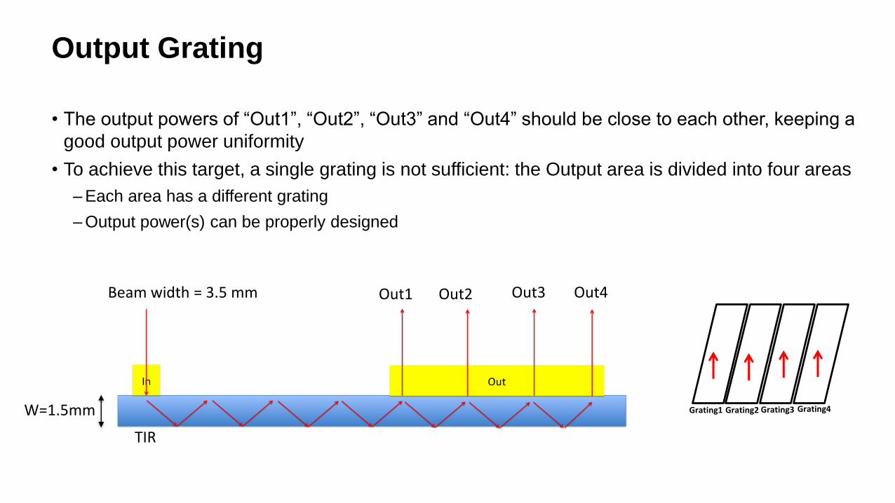
Output Grating
• The output powers of “Out1”, “Out2”, “Out3” and “Out4” should be close to each other, keeping a
good output power uniformity
• To achieve this target, a single grating is not sufficient: the Output area is divided into four areas
– Each area has a different grating
– Output power(s) can be properly designed
W=1.5mm
Beam width = 3.5 mm Out1 Out2 Out3 Out4
TIR
Grating1 Grating3 Grating4Grating2
Output Gratings
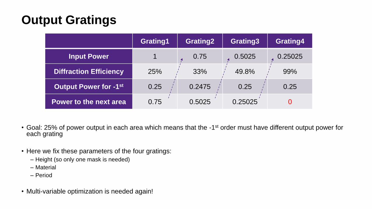
• Goal: 25% of power output in each area which means that the -1st order must have different output power for each grating
• Here we fix these parameters of the four gratings:
– Height (so only one mask is needed)
– Material
– Period
• Multi-variable optimization is needed again!
Grating1 Grating2 Grating3 Grating4
Input Power 1 0.75 0.5025 0.25025
Diffraction Efficiency 25% 33% 49.8% 99%
Output Power for -1st 0.25 0.2475 0.25 0.25
Power to the next area 0.75 0.5025 0.25025 0
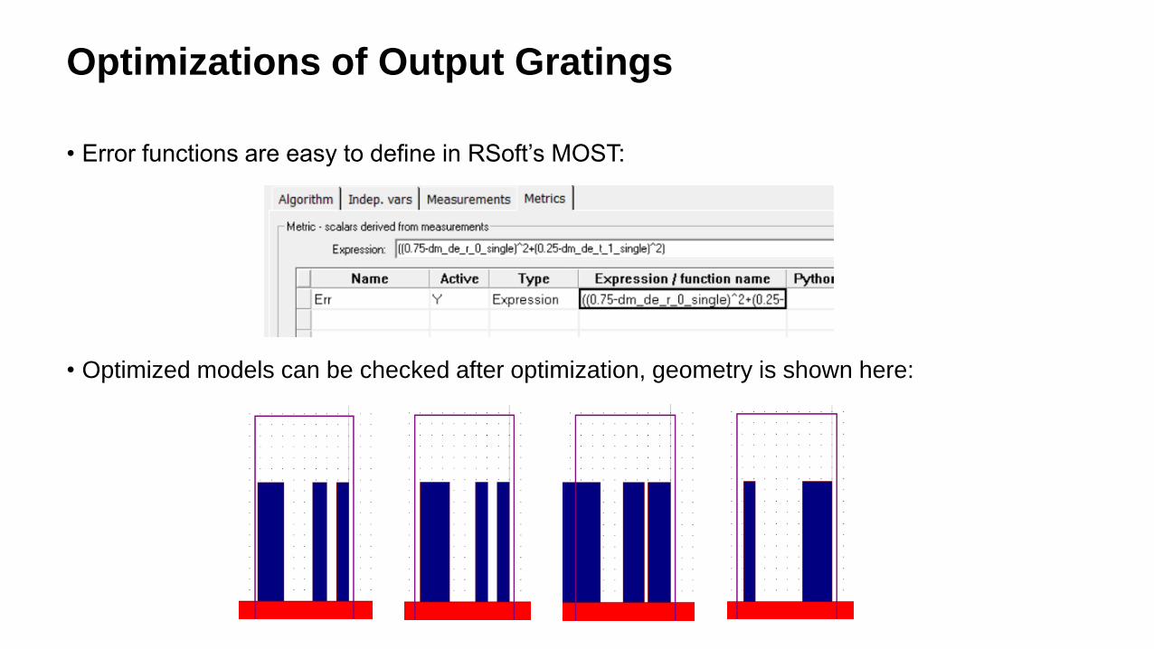
Optimizations of Output Gratings
• Error functions are easy to define in RSoft’s MOST:
• Optimized models can be checked after optimization, geometry is shown here:
Gratings for EPE
• The design of the EPE includes the second incident angle (theta)
• The grating was designed to split the light as shown below
θ
xy plane
~4*3.5 mm
First time
Ou
t pu
t3.5 mm
EPE1
EPE2
EPE3
EPE4
Gratings for EPE
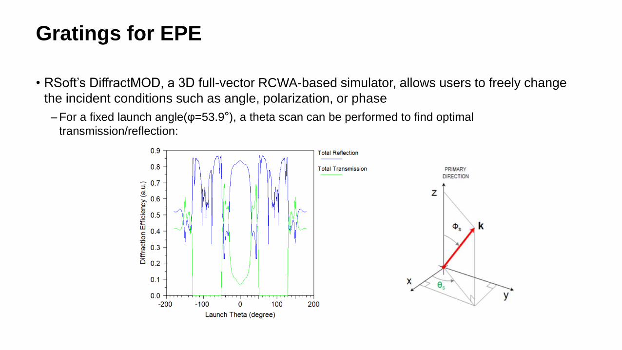
• RSoft’s DiffractMOD, a 3D full-vector RCWA-based simulator, allows users to freely change
the incident conditions such as angle, polarization, or phase
– For a fixed launch angle(φ=53.9°), a theta scan can be performed to find optimal
transmission/reflection:
Optical System in LightTools
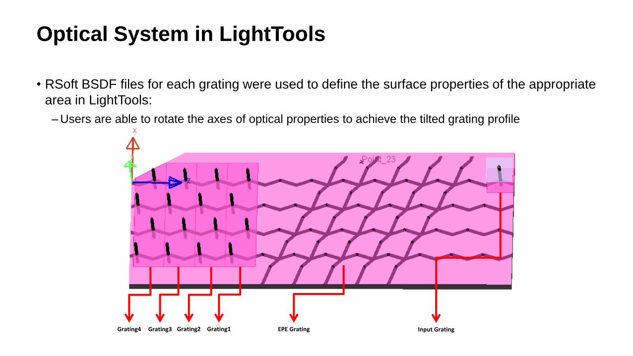
• RSoft BSDF files for each grating were used to define the surface properties of the appropriate
area in LightTools:
– Users are able to rotate the axes of optical properties to achieve the tilted grating profile
Grating1Grating3Grating4 Grating2 EPE Grating Input Grating
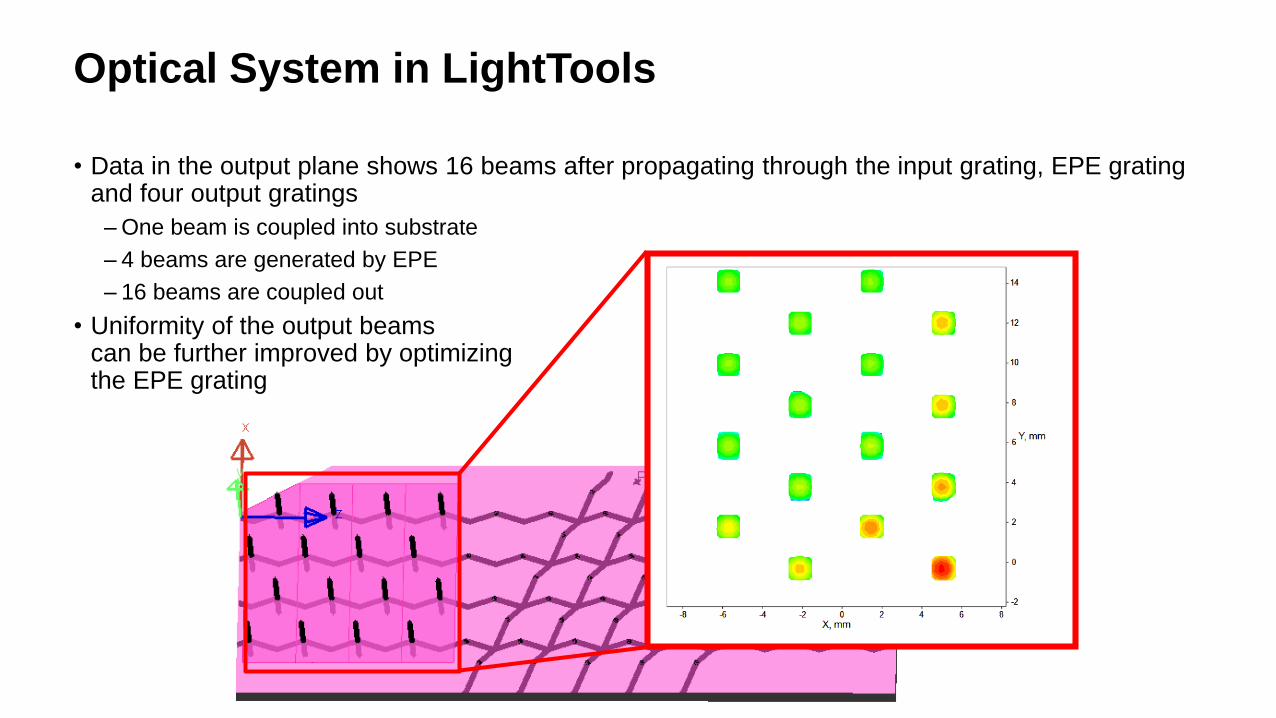
Optical System in LightTools
• Data in the output plane shows 16 beams after propagating through the input grating, EPE grating and four output gratings
– One beam is coupled into substrate
– 4 beams are generated by EPE
– 16 beams are coupled out
• Uniformity of the output beamscan be further improved by optimizingthe EPE grating
Conclusion
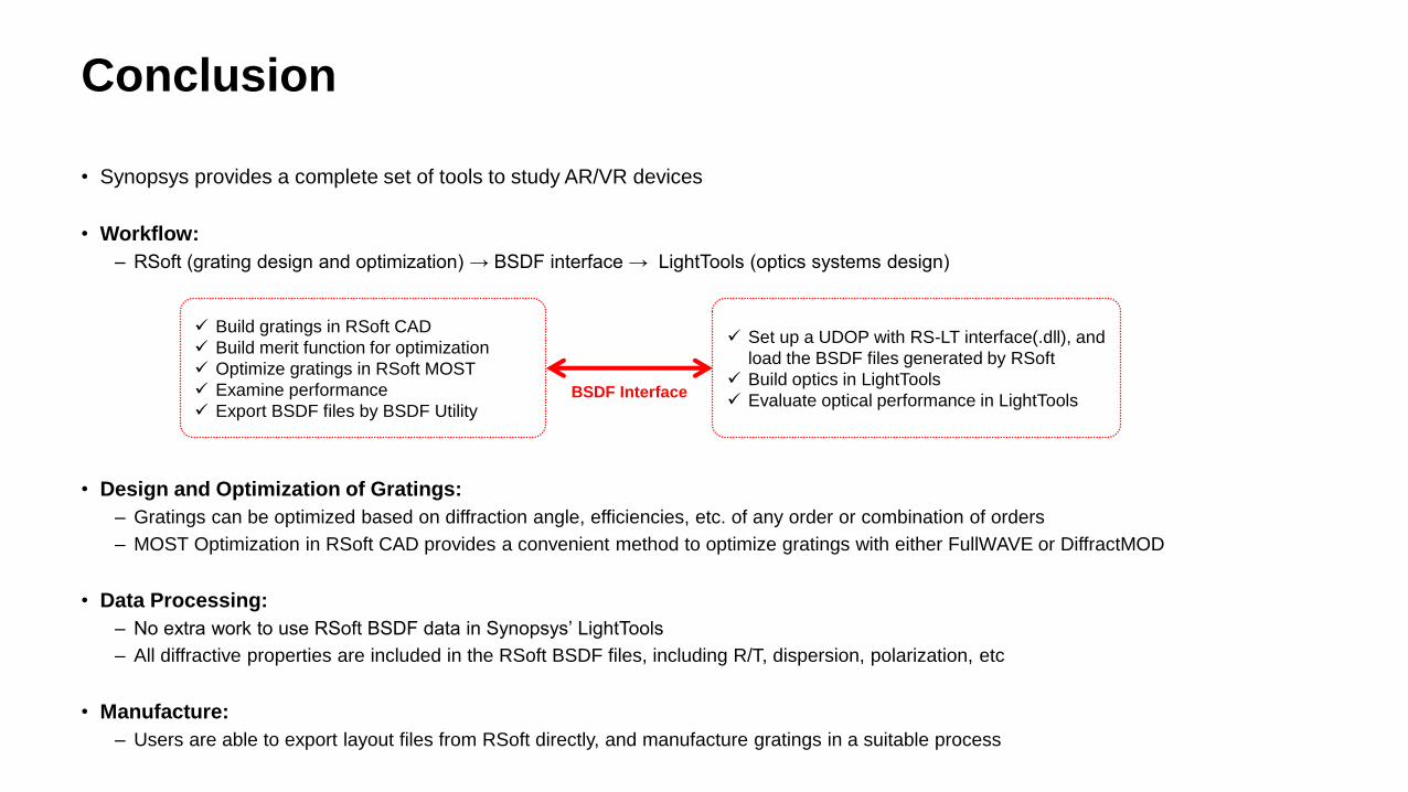
• Synopsys provides a complete set of tools to study AR/VR devices
• Workflow:
– RSoft (grating design and optimization) → BSDF interface → LightTools (optics systems design)
• Design and Optimization of Gratings:
– Gratings can be optimized based on diffraction angle, efficiencies, etc. of any order or combination of orders
– MOST Optimization in RSoft CAD provides a convenient method to optimize gratings with either FullWAVE or DiffractMOD
• Data Processing:
– No extra work to use RSoft BSDF data in Synopsys’ LightTools
– All diffractive properties are included in the RSoft BSDF files, including R/T, dispersion, polarization, etc
• Manufacture:
– Users are able to export layout files from RSoft directly, and manufacture gratings in a suitable process
38
Build gratings in RSoft CAD
Build merit function for optimization
Optimize gratings in RSoft MOST
Examine performance
Export BSDF files by BSDF Utility
Set up a UDOP with RS-LT interface(.dll), and
load the BSDF files generated by RSoft
Build optics in LightTools
Evaluate optical performance in LightToolsBSDF Interface