design of ip multimedia subsystem service switching function (im
TRANSCRIPT

Design of
IP Multimedia subsystem
Service Switching Function (IM-SSF)
Application Server Architecture
V i k r a m K u m a r K u l k a r n i
Thesis report Master of science in Internetworking
Master of Science Thesis Stockholm, Sweden 2005
IMIT/TSLAB-2003-05

Design of IM-SSF application server architecture Vikram Kumar Kulkarni (800724-A139) TSLAB/IMIT
Abstract
3G wireless networks technologies are experience a rapid development in the recent past.
And the wireless networks shifting towards packet switched networks, this is largely due
to introduction of a new component called IP multimedia Subsystem which responsible
for providing interactive multimedia communications to the mobile subscriber. Providing
intelligent network and value added services to IMS users is very essential for the
operators to get the customer satisfaction. IP multimedia subsystem service switching
function (IM-SSF) is responsible for providing intelligent network services by interfacing
SIP signaling in the IMS to the CAMEL Application Part (CAP) towards legacy
gsmSCF. This thesis work is aimed to design the architecture of IM-SSF. A modular
structured, load balanced, extensible and standard compliant IM-SSF architecture has
been designed based on the 3GPP standards. Necessary recommendations have been
made to help the developers to develop IM-SSF in an efficient way.
Keywords:
IP Multimedia subsystem (IMS), CAMEL, Intelligent networking, 3G Application
servers.

Design of IM-SSF application server architecture Vikram Kumar Kulkarni (800724-A139) TSLAB/IMIT
Executive summary
This report presents the design issues of “Internet Protocol Multimedia Subsystem
Service Switching Function (IM-SSF)”. In this report I will be discussing about the
internal functional architecture of IM-SSF and it’s Internetworking with Internet Protocol
Multimedia Subsystem (IMS).
Acknowledgements I would like to thank the following people helped me to accomplish this task.
- Anders Olin;
- Lars Kari;
- Paul Martlew;
- Peter Sjögren;
- Johan Montelius;

Design of IM-SSF application server architecture Vikram Kumar Kulkarni (800724-A139) TSLAB/IMIT
INDEX
ABSTRACT....................................................................................................................... 2
EXECUTIVE SUMMARY .............................................................................................. 3
ACKNOWLEDGEMENTS ............................................................................................. 3
INDEX................................................................................................................................ 4
1. INTRODUCTION......................................................................................................... 7
1.1 SCOPE............................................................................................................................ 7
1.2 LIMITATIONS ................................................................................................................ 7
1.3 DOCUMENT STRUCTURE ............................................................................................... 7
2. METHOD ...................................................................................................................... 9
3. INTRODUCTION TO IM-SSF ................................................................................. 10
4. BACKGROUND TECHNOLOGIES ....................................................................... 11
4.1. SESSION INITIATION PROTOCOL................................................................................ 11
4.2 3G IP MULTIMEDIA SUBSYSTEM................................................................................ 14
4.3 INTELLIGENT NETWORKING AND CAMEL ............................................................... 17
5. IM-SSF INTERNETWORKING .............................................................................. 22
5.1 INTERNETWORKING WITHIN IP MULTIMEDIA SUBSYSTEM ....................................... 22
5.2 INTERFACES FOR AN IM-SSF SERVER....................................................................... 23
5.3 DESCRIPTION OF CAMEL SUBSCRIBER DATA (MULTIMEDIA CAMEL
SUBSCRIPTION INFORMATION (IM-CSI))........................................................................ 24
5.4 DESCRIPTION OF CAMEL STATE MODELS .............................................................. 27
5.5 ORIGINATING CAMEL BASIC CALL STATE MODEL (O-IM-BCSM)...................... 30
5.6 TERMINATING CAMEL BASIC CALL STATE MODEL (T-IM-BCSM) ..................... 35
6. INFORMATION FLOWS (MESSAGES TO AND FROM THE IM-SSF) .......... 39
6.1 IM-SSF TO GSMSCF INFORMATION FLOWS.............................................................. 39

Design of IM-SSF application server architecture Vikram Kumar Kulkarni (800724-A139) TSLAB/IMIT
6.2 GSMSCF TO IM-SSF INFORMATION FLOWS.............................................................. 42
6.3 GSMSCF – IM-SSF INFORMATION FLOWS FOR MRFC RELATED OPERATIONS ...... 46
6.4 IM-SSF TO HSS INFORMATION FLOWS ..................................................................... 47
6.5 HSS TO IM-SSF INFORMATION FLOWS ..................................................................... 48
6.6 GSMSCF TO HSS INFORMATION FLOWS.................................................................... 49
6.7 HSS TO GSMSCF INFORMATION FLOWS.................................................................... 49
7. THE DESIGN OF THE IM-SSF ARCHITECTURE.............................................. 52
7.1 THE IM – SSF ARCHITECTURE GIVEN IN STANDARDS............................................... 52
7.2. IM-SSF ARCHITECTURE DESIGNED BY ME ............................................................... 54
7.3 THE COMPONENTS OF IM-SSF APPLICATION SERVER............................................. 57
7.4 SIP PARSER................................................................................................................. 60
7.5 SIP REGISTRATION INTO IM-SSF.............................................................................. 61
7.6 TRIGGER MANAGER.................................................................................................... 64
7.7. HANDLING OF MOBILE ORIGINATED CALLS IN THE IM-SSF.................................... 68
8. IMPLEMENTATION PROPOSAL.......................................................................... 88
8.2 IMPLEMENTATION PHASES ......................................................................................... 90
9. SERVICE MODELS .................................................................................................. 93
9.1 PRE-PAID SERVICE MODEL ......................................................................................... 93
9.2 VIRTUAL PRIVATE NETWORKS (VPN) ...................................................................... 96
10. TRAFFIC CASE ....................................................................................................... 99
10.1 THE IMS TERMINAL SENDS AN INVITE REQUEST................................................ 102
10.2 THE ORIGINATING P-CSCF PROCESSES THE INVITE REQUEST.......................... 107
8.3 AT THE ORIGINATING S-SSCF ................................................................................ 109
10.4 AT IM-SSF ............................................................................................................. 111
10.5 AT GSMSCF ............................................................................................................ 111
10.6 BACK AT IM-SSF ................................................................................................... 111
10.5 BACK AT S-CSCF ................................................................................................... 113
10.6 AT BGCF................................................................................................................ 113
10.7 AT MEDIA GATEWAY CONTROL FUNCTION (MGCF)............................................ 113
10.8 AT SIGNALING GATEWAY ....................................................................................... 113
10.9 AT TERMINATING LOCAL EXCHANGE (TLE) ....................................................... 113
10.10 AT CALLEE ............................................................................................................ 113
10.11 TERMINATING PARTY RESPONDS WITH ISDN ALERTING MESSAGE ............... 113

Design of IM-SSF application server architecture Vikram Kumar Kulkarni (800724-A139) TSLAB/IMIT
10.12 CALLEE ANSWERS THE CALL................................................................................ 114
10.13 CALLEE DISCONNECTS THE CALL ........................................................................ 114
11. RESULTS ................................................................................................................ 116
12. CONCLUSIONS ..................................................................................................... 117
REFERENCES.............................................................................................................. 118

Design of IM-SSF application server architecture Vikram Kumar Kulkarni (800724-A139) TSLAB/IMIT
Thesis report – Vikram Kumar Kulkarni Page 7 of 118
1. Introduction This is a design document of an “IP multimedia subsystem service switching function
(IM-SSF) Application Server”. In this document I will be discussing the design issues of
IM-SSF, Internals of an IM-SSF and I present IM-SSF functional architecture. CAMEL
in IP multimedia environment will be discussed in detail. Finally I discussed traffic cases
involving IM-SSF and intelligent network services such as pre-paid an IM-SSF.
1.1 Scope In this project I will design and prototype the IP multimedia subsystem service switching
function (IM-SSF) Application Server. As part of this project a specification of an IM-
SSF is written, which can be used as a start document for developing an IM-SSF server.
So the specification will cover the functional and architectural issues of an IM-SSF.
In general any SSF is very complex node in telecom network. To build SSF of GSM
network in Ericsson 100 people have worked for 2 years. It has many deifferent internal
process components, which are again complex process. The 3GPP specification are crude
and only gives description of some basic processes. Much of design tasks are left to the
product vendors. The task is to identify the components of IM-SSF, their functionality
and design the overall architecture of IM-SSF.
1.2 Limitations As per the scope of this thesis some of the issues relating to design of IM-SSF are not
addressed in this report. And some issues are not investigated in very detailed. For
example practical issues like operations and maintenance (OAM), Statistics, Load
balancing are not investigated in this work. Handling of mutli-party calls and follow on
calls by IM-SSF are not investigated in this thesis work.
1.3 Document structure The document is preliminarily intended for Mobile Arts AB. The reader is expected to
have the knowledge of Session Initiation protocol, IP Multimedia Subsystem (IMS) and
Customized Applications for Mobile Enhanced Logic (CAMEL).
The document is divided chapters, sections and sub sections.
Chapter 1 – Introduction: In this chapter a brief introduction of this work is presented.
Chapter 2 – method. In this chapter the method followed for the thesis work is described
Chapter 3 – Introduction to IM-SSF: In this chapter a brief introduction of IM-SSF is
presented.
Design of IM-SSF application server architecture Vikram Kumar Kulkarni (800724-A139) TSLAB/IMIT
Thesis report – Vikram Kumar Kulkarni Page 8 of 118
Chapter 4 – background technologies: This chapter describes the background
technologies i.e. SIP, IMS and CAMEL.
Chapter 5 – IM-SSF Internetworking: In this chapter the Internetworking of IM-SSF with
in IMS is explained. The description of basic elements of CAMEL such as the IP
multimedia CAMEL subscription information, IP multimedia Basic Call State Model (O-
IM-BCSM) and Terminating IP multimedia Basic Call State Model (O-IM-BCSM)
given in this chapter.
Chapter 6 – Information Flows (Messages to and from the IM-SSF): In this chapter
information flows between IM-SSF and gsmSCF, IM-SSF and Home Subscriber Server
(HSS), gsmSCF and HSS are explained. A large part in this section are taken from
standards mainly Customised Applications for Mobile network Enhanced Logic
(CAMEL) Phase 4 - Stage 2; IM CN Interworking 3GPP 23.278 Release 5 [5].
Chapter 7 – The IM-SSF Architecture: In this chapter the architecture if IM-SSF is
described in detail. In this public version of report only originating half of the IM-SSF is
described. The terminating half of the IM-SSF is not described in this report. This chapter
is based on Customised Applications for Mobile network Enhanced Logic (CAMEL)
Phase 4 - Stage 2; IM CN Interworking 3GPP 23.278 Release 5 [5]. But the large part of
architecture is designed by me. And large part of text is analysis and observations of the
standard. This chapter is core of this report. Some back ground information of this
chapter is based on
• 3GPP 23.218 Release 5 IP Multimedia Subsystem (IMS); Stage 2
• 3GPP 23.228 Release 5 IP Multimedia (IM) session handling; IM call model
Chapter 8 – Implementation proposal: In this chapter a phase wise implementation
proposal is suggested.
Chapter 9 – Service models: In this chapter I have described a CAMEL operations
required to provide pre-paid and VPN. This chapter is based on 3GPP 23.078 Release 5
Customised Applications for Mobile network Enhanced Logic (CAMEL) Phase 4- Stage
2.
Chapter 10 – Traffic case: In this chapter a very detailed traffic case is presented. This
chapter is based on
• 3GPP 23.218 Release 5 IP Multimedia Subsystem (IMS); Stage 2
• 3GPP 23.228 Release 5 IP Multimedia (IM) session handling; IM call model
Chapter 11: Results
Chapter 13: Conclusions

Design of IM-SSF application server architecture Vikram Kumar Kulkarni (800724-A139) TSLAB/IMIT
Master thesis report – Vikram Kumar Kulkarni Page 9 of 118
2. Method This project is specified by Paul Mertlew of Mobile arts AB, and given some guidelines
to carryout this work. I have done a lot of literature study for this project. In the course of
project I had some meeting with my supervisor once in every 2 or 3 weeks. In the
meetings I had some inputs from them on where to look for information, what way I
should approch to solve this problem. My supervisor who had several decades of
experience in telecom industry, his guidelines, suggestions and recoomendations have
shown me the way to go for carrying out this work.
I have done a lot of literature study for this project. Before starting this project I have no
knowledge of telecom domain. IM-SSF is a softswitch, which sits in between circuit
switched GSM network, and packed switched 3G IMS network. For this work, I had to
learn the telecom systems, SS7 signalling, signalling and architecture of GMS network.
Intelligent networking, CAMEL is another bigger part of this project, which I had no
knowledge before. I read and understood the telecom systems, SS7 signalling,
architecture of GSM and basics of Intelligent networking from the text books and
tutorials from Internet. To get the deeper understanding CAMEL which is one of the
main technology involved in this work, I had looked into 3GPP specifications.
I understood the nuts and bolts of IMS, CAMEL in IMS from 3GPP specifications. In the
specification the processes are described using SDL language. These SDL diagrams
given in 3GPP specification describes heart processes of the IM-SSF server, based on
which one can build standard based IM-SSF server. I learned SDL to understand the
processes of IM-SSF that are defined in standard, later I did deep examination of these
processes. Finally I designed the IM-SSF architecture of IM-SSF and presented a design
document to my supervisor. Based on his comments, I have refrained the whole design
for two more times before I got the final design.
In general any SSF is very complex node in telecom network. To build SSF in GSM
network in Ericsson, almost 100 people have worked for 2 years. It has many deifferent
internal process components, which are again complex process. The 3GPP specification
are crude and only gives description of some basic processes. Much of design tasks are
left to the product vendors. The task is to identify the components of IM-SSF, their
functionality and design the overall architecture of IM-SSF.

Design of IM-SSF application server architecture Vikram Kumar Kulkarni (800724-A139) TSLAB/IMIT
Master thesis report – Vikram Kumar Kulkarni Page 10 of 118
3. Introduction to IM-SSF In GSM networks the intelligent network services are provided by Customized
Applications for Mobile Enhanced Logic (CAMEL). CAMEL will provide the GSM
operator with the ability to offer operator specific services based on IN service logic to a
GSM subscriber. Some of major CAMEL applications include pre-paid and Virtual
Private Network (VPN) services.
The GSM Networks are equipped with legacy CAMEL entities which are build over past
several years. The idea is to use the functionality of CAMEL entities (especially gsm
Service Control Function, gsmSCF) by providing an interface to gsmSCF. The IM-SSF
allows IMS subscribers to interface directly to legacy CAMEL services such as pre-paid
and VPN.
IM- SSF is a SIP application server in 3G IMS responsible for handling CAMEL
intelligent network operations. IM-SSF interfaces SIP to CAP.
From the IMS point of view IM-SSF is just a SIP application server. IM-SSF acts as a
SIP back to back user agent (SIP B2BUA). It breaks the call coming from originating
party and creates a new call leg towards the terminating party, thus allowing
modifications to session. From gsmSCF point of view IM-SSF acts similarly like a
gsmSSF.
However, IM-SSF can only provide intelligent network services for the calls based on
ISDN numbers. Providing intelligent network services to the calls destined to SIP user
might require another SIP application server.
The most related specification for this work is Customised Applications for Mobile
network Enhanced Logic (CAMEL) Phase 4 - Stage 2; IM CN Interworking 3GPP
23.278 Release 5 [5]. The other related specifications are
1. 3GPP 23.218 Release 5 IP Multimedia Subsystem (IMS); Stage 2
2. 3GPP 23.228 Release 5 IP Multimedia (IM) session handling; IM call model
3. 3GPP 23.078 Release 5 Customised Applications for Mobile network Enhanced
Logic (CAMEL) Phase 4- Stage 2.
In the subsequent sections I will be describing Session initiation protocol, IMS and
CAMEL.

Design of IM-SSF application server architecture Vikram Kumar Kulkarni (800724-A139) TSLAB/IMIT
Master thesis report – Vikram Kumar Kulkarni Page 11 of 118
4. Background technologies
4.1. Session initiation protocol
In 1996, IETF had developed basic semantics for multimedia communications on
Internet. Based on IETF guidelines, there were two protocols for multimedia
communications are proposed, one is Session initiation protocol (SIP) by mark handley,
and another is Simple conference invitation protocol by henning schulzrinne. Later these
two protocols are merged to form Session Initiation protocol and defined in RFC 2543.
SIP protocol gained a new momentum when 3GPP adopted SIP as signaling protocols,
since then many extensions are proposed to basic SIP protocol to enhance the
functionality of SIP and the extended SIP protocol is defined in RFC 3261.
“(SIP) an application-layer control (signaling) protocol for creating, modifying, and
terminating sessions with one or more participants. These sessions include Internet
telephone calls, multimedia distribution, and multimedia conferences” [8]
Signaling is mechanism used to setup and terminate telephone calls. And SIP is a
signaling protocol for Internet network. SIP [8] is a text-based protocol, similar to HTTP
and SMTP, for initiating interactive communication sessions between users. HTTP and
SMTP are the most successful protocols in Internet, and SIP barrows principles from
these protocols. SIP devices are addressed by SIP URI’s similar to that of e-mail address.
SIP URI’s can have different forms, can also represent telephone numbers.
SIP provides ability to discover end user (SIP client) in the Internet. The SIP terminal
will have more intelligence than traditional phone terminals. SIP enabled network has
different entities, and they are explained here
4.1.1. SIP Proxy Server
A proxy server receives SIP requests from a user agent or another proxy server and
forwards the SIP the same request to the appropriate SIP server. SIP proxy can also route
the SIP messages.
4.1.2. SIP Redirect Server
A redirect server receives request from user agent or proxy redirects the same node to try
another place. For that redirect server sends 3XX response.
4.1.3 SIP Registrar
SIP registration server handles the registration of SIP users of a particular domain. For
each SIP domain there will be a SIP registration server. This server processes SIP
REGISTER message, upon a valid registration request from a SIP client the SIP
registration server updates the user location in location server [8].

Design of IM-SSF application server architecture Vikram Kumar Kulkarni (800724-A139) TSLAB/IMIT
Master thesis report – Vikram Kumar Kulkarni Page 12 of 118
4.1.4 Location Server
Location server contains the information about the user location. It consist a database that
stores the registered users IP address [8].
4.1.5 User Agent
The User Agent (UA) is a piece of software running in the SIP terminals [8].
The UA consists of two parts, the User Agent Client (UAC) and the User Agent Server
(UAS). UAC can generate SIP message and send it to the SIP proxy server. And UAS
can receive the incoming messages, on the terminal [8].
As a signaling protocol on Internet SIP performs the following session related functions:
• Session setup
• Media negotiation
• Session modifications
• Session termination and cancellation
• Mid call signaling
• Call controlling
• QoS Setup
SIP also performs non-session-related functions such as
• Mobility management
• Instant message
• Event subscription and notification
• Authentication and security
SIP is used in conjunction with SDP, RTP to provide VoIP services over IP network.
4.1.6 Session description protocol (SDP)
Session description protocol (SDP) [9] is used to convey the session description to the
remote user. SIP uses SDP as session description protocol. There is only one protocol
defined so far for session description and that is SDP. SDP is carried as the message body
in SIP messages.
4.1.7 Real-time transport protocol (RTP)
Real-time transport protocol [10] is used to carry the interactive media streams such as
voice and video. It is RTP uses unreliable UDP as a transport protocol. But RTP provides
some extent of reliability with help of time stamp and sequence numbers. The sequence
number and time stamps are also used to replay the original media.

Design of IM-SSF application server architecture Vikram Kumar Kulkarni (800724-A139) TSLAB/IMIT
Master thesis report – Vikram Kumar Kulkarni Page 13 of 118
4.1.8 SIP messages
Like any other Internet protocol SIP performs its functions using messages. SIP messages
are of two types one is SIP request types know as SIP methods, and SIP responses. There
are 6 basic SIP messages defined in rfc2543, and several extensions are proposed later.
SIP responses are similar to HTTP, represented by numerical codes. The table1 shows the
SIP methods, table 3 shows SIP responses.
Method Description INVITE SIP protocol uses INVITE message to setup session between two
US’s. INVITE message also carries a session description that caller
wish to establish
ACK SIP ACK is used to acknowledge the final response of SIP INVITE.
And so SIP INVITE is only SIP method that involves 3 way hand-
shake.
BYE A successfully established SIP session can be terminated gracefully
using SIP BYE message.
CANCEL SIP session can be cancelled using SIP CANCEL message. SIP
session can be cancelled before establishing session, and just after
sending the SIP INVITE message
REGISTER SIP REGISTER message is used in registration process of SIP UA. SIP
UA sends SIP REGISTER message to SIP registrar for registration.
OPTIONS SIP Options message is used as query of options and capabilities.
INFO INFO method is used for mid-call signaling transport
PRACK Provisional response acknowledgement PRACK is used to
acknowledge the provisional responses to provide reliability for
provisional messages.
COMET COMET (conditions met) method is used to convey the other party
that the conditions are fulfilled
REFER REFER message is used to transfer a call to another URI, this
message is useful for call center, Automatic call distribution
applications.
SUBSCRIBE SUBSCRIBE method is used for subscription of a notification for a
particular event in SIP network.
UNSUBSCRIBE UNSUBSCRIBE method is used to cancel the subscription of an
event.
NOTIFY A subscribed event can be notified by SIP NOTIFY method.
MESSAGE An instant message is transported using MESSAGE method
INVITE, ACK, BYE, CANCEL, REGISTER and OPTIONS are basic SIP messages
defined in RFC 2543, other messages are defined as extensions.
SIP requests can be answered with SIP response messages. Like HTTP responses in SIP
responses are numerical are also called as response codes. Table 2 shows SIP response
codes

Design of IM-SSF application server architecture Vikram Kumar Kulkarni (800724-A139) TSLAB/IMIT
Master thesis report – Vikram Kumar Kulkarni Page 14 of 118
Method Description 1XX 1XX is a provisional response, request is being processed.
2XX 2XX denotes successful SIP request. For example 200 OK.
3XX 3XX is a Redirection response; upon request from 3XX response a
client should retry the request at another location.
4XX 4XX represents client error; The request was not processed due to
error in SIP request. The client can retry after correcting the SIP
request message.
5XX 5XX denotes server error; request is not processed because of error
at receiver.
6XX Global failure; failure every where, request cannot be retried.
4.2 3G IP Multimedia subsystem 3G IP multimedia subsystem (IMS) is a new module introduced in UMTS. The main
purpose of IMS is to provide IP based multimedia communication in 3G Networks. SIP is
adopted as signaling protocol in the IP multimedia subsystem [2].
The IMS is a convergence technology between cellular world and Internet. The cellular
system has benefit of having coverage every where. And Internet enables rich services
like e-mail, instance messaging and multimedia communications at lower price. By
converging both networks the user can benefit best of both, that is user can get Internet
services every where [12].
The main responsibilities of IMS are [12]
� Providing negotiable Quality of Service (QoS)
� Mechanism for Charging
� Flexibility to create new services rapidly.
In the IMS services are provided by application servers. Creation of new requires
providing a new application and configuring user profile in Home Service Subscriber.
IMS also provides a way to negotiate and provide QoS for the multimedia sessions
between two users. The IMS provides some mechanism for charging the end user.
The components of IMS are shown in figure 1
� Call session control functions (CSCF)
o Proxy call session control function (P-CSCF)
o Interrogating call session control function (I-CSCF)
o Serving call session control function. (S-CSCF)
� Home subscriber server (HSS)
� Subscriber location functions (SLF)
� Application servers
� Breakout gateway control function (BGCFs)
� Media gateway controller.

Design of IM-SSF application server architecture Vikram Kumar Kulkarni (800724-A139) TSLAB/IMIT
Master thesis report – Vikram Kumar Kulkarni Page 15 of 118
In this section I will describe all the above components briefly.
Figure 1 – IP multimedia subsystem
Call session control function (CSCF)
Call session control functions are SIP servers responsible for handling SIP signaling
within IMS.
Proxy call session control function (P-CSCF)
Proxy call session control function (P-CSCF) is the first point of contact in the IMS for a
Mobile terminal. It is responsible to authenticate IMS terminal. P-CSCF is an
inbound/outbound SIP proxy server. P-CSCF performs security, authentication, and
policy enforcement functions. P-CSCF compresses and de-compresses SIP messages
transmitting/receiving from mobile terminal to save bandwidth over radio link.
Interrogating call session control function (I-CSCF)
I-CSCF acts as representative SIP server for a given IMS. Its IP address is listed in DNS.
All SIP invitation messages destined home network SIP user are forwarded to I-CSCF.
Interrogating call session control function selects the appropriate S-CSCF and forwards
the SIP request to S-CSCF.
IP Multimedia Subsystem.
I-CSCF
S-CSCF
P-CSCF
HSS
SIP AS IM-SSF OSA-SCS

Design of IM-SSF application server architecture Vikram Kumar Kulkarni (800724-A139) TSLAB/IMIT
Master thesis report – Vikram Kumar Kulkarni Page 16 of 118
Serving call session control function (S-CSCF)
Serving call session control function (S-CSCF) acts as a SIP registrar server for IMS
users. It handles the processing of SIP register messages in the IMS. It is central node of
IMS signaling system. Based on the user profiles, the S-CSCF provides services by
forwarding the SIP messages to appropriate application servers. Services provision is
IMS is mainly done by S-CSCF. All SIP messages sent/received by IMS terminal will
traverse through S-CSCF, S-CSCF inspects all messages and determines weather to
trigger one or more application servers. It routes the SIP invitation messages originated
from home network user to appropriate next hop. The next hop could be another IMS
user, Internet user, or PSTN user.
Home Subscriber server and subscriber location function
HSS stores all the subscription information of home subscribers. The subscription
information includes location information, security information and user profile
information. In case of number of subscribers are very high, the network requires more
than one HSS to store the subscription information. SLF is a database that maps the
registered users addresses to HSS. If there is only one HSS, the IMS network does not
require SLF [12].
IMS terminals (Mobile terminals) are SIP user agents. And the terminals have SIP
addresses called SIP URI.
Breakout gateway control function (BGCF)
The breakout gateway control function is SIP server. The main function of BGCF is to
provide routing functionality for a call whose destination is a telephone number [12].
The PSTN/CS gateway.
The PSTN gateway provides an interface towards a circuit switched network, through
which the IMS terminals can make and receive calls to and from PSTN [12].
4.2.1 IMS registration
To use IMS services, the terminal has to register with IMS. The IMS registration process
involves several steps like getting IP access connectivity, P-CSCF discovery and IMS
level registration as show in figure 2
IMS is an IP network, and reachable via a IP connectivity access network (IP-CAN) such
as GPRS, or WLAN. So IMS terminal needs to connect to a CAN and acquire an IP
address from CAN. In the next step terminal needs address of P-CSCF, which is
inbound/outbound proxy server for IMS terminals. If IP-CAN is GPRS, terminal can find
P-CSCF address in GPRS attachment procedure. Otherwise terminal can request address
of P-CSCF (SIP domain name of P-CSCF) from DHCP server. After obtaining the
domain name of P-CSCF, the terminal can request DNS for P-CSCF’s IP address.

Design of IM-SSF application server architecture Vikram Kumar Kulkarni (800724-A139) TSLAB/IMIT
Master thesis report – Vikram Kumar Kulkarni Page 17 of 118
After discovering P-CSCF IP address, the terminal tries to register with IMS. This
procedure also called as IMS level registration. In IMS level registration, the terminal
request authorization to use IMS service. IMS level registration is done by using SIP
register request.
Figure 2: Registration at IMS level
IMS level registration is shown in figure 2. IMS terminal sends SIP REGISTER request
to P-CSCF. In the REGISTER request IMS terminal sends its IP address and domain
name of its home IMS network. After receiving SIP REGISTER, the P-CSCF requests
DNS server for IP address of I-CSCF which is located in IMS home network. P-CSCF
forwards the SIP request to the I-CSCF in the home network.
On receipt of SIP REGISTER message I-CSCF checks with HSS weather IMS user has
already allocated an S-CSCF. If there is an allocated S-CSCF, then HSS returns the
address of S-CSCF, otherwise HSS returns set of S-CSCF, capable of handling that
particular IMS user. I-CSCF selects an appropriate S-CSCF from the set of S-CSCF’s
returned by HSS. I-CSCF forwards the SIP request to the selected S-CSCF. S-CSCF
authenticates the user. If the authentication is successful, S-CSCF informs the HSS that
the user is registered and downloads the user profile from HSS.
4.3 Intelligent networking and CAMEL Customized Application Mobile Enhanced Logic defines intelligent network functionality
in GSM networks. Using CAMEL a GSM operator can provide operator specific services
to its subscribers. ETSI has started working on intelligent networking in GSM from 1994,
since then CMALE was evolved in 4 phases. The first phase is released in 1997, second
phase is released in 1998, and third phase is released in 1999 and now fourth is phase is
in use. The CAMEL phase 4 is specified in “3GPP 23.078 Release 5
Customised Applications for Mobile network Enhanced Logic (CAMEL) Phase 4- Stage
2” [12].
IMS terminal P-CSCF I-CSCF P-CSCF S-CSCF
REGISTER
REGISTER
DIAMETER UAR
DIAMETER UAA
REGISTER
DIAMETER SAR
DIAMETER SAA
200 OK
200 OK
200 OK
Design of IM-SSF application server architecture Vikram Kumar Kulkarni (800724-A139) TSLAB/IMIT
Master thesis report – Vikram Kumar Kulkarni Page 18 of 118
The term intelligent networking is introduced by Bellcore in the USA in 1980s. Since
then the IN concept has gradually developed, and used worldwide in telecom networks.
Intelligent networking means separation of logic controlling services from the basic call
control function in existing telephone switches. The benefit of IN is separation of service
logic into a separately controllable entity, where services can be provided modified and
controlled by operator rather than switch manufacturers. This provides ability for
operators to develop operator specific services efficiently and without depending heavily
on switch manufacturers. Before IN concept is introduced the operators had to heavily
depended on switch manufacturers to provide competitive value added services to its
subscribers. Example of value added services are VPN, toll free, calling card.
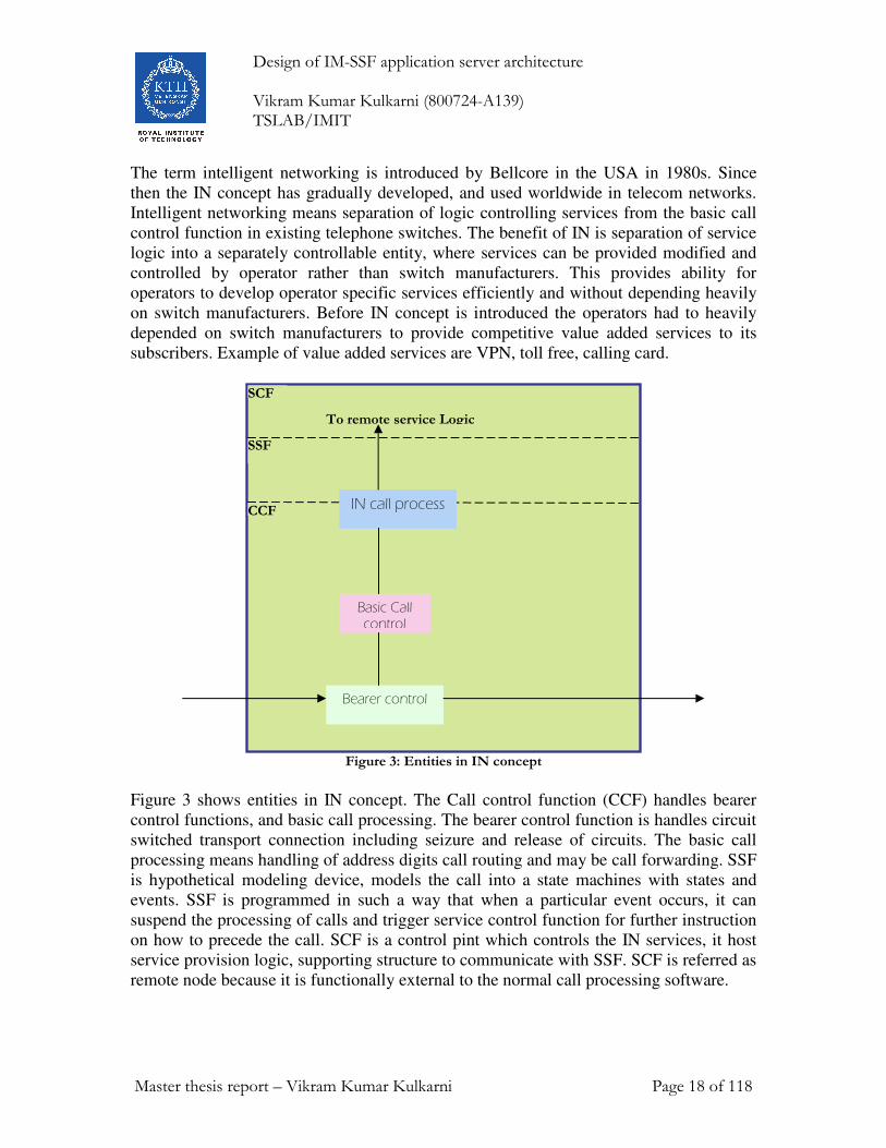
Figure 3: Entities in IN concept
Figure 3 shows entities in IN concept. The Call control function (CCF) handles bearer
control functions, and basic call processing. The bearer control function is handles circuit
switched transport connection including seizure and release of circuits. The basic call
processing means handling of address digits call routing and may be call forwarding. SSF
is hypothetical modeling device, models the call into a state machines with states and
events. SSF is programmed in such a way that when a particular event occurs, it can
suspend the processing of calls and trigger service control function for further instruction
on how to precede the call. SCF is a control pint which controls the IN services, it host
service provision logic, supporting structure to communicate with SSF. SCF is referred as
remote node because it is functionally external to the normal call processing software.
IN call process
Basic Call control
Bearer control
SSF
CCF
To remote service Logic
SCF
Design of IM-SSF application server architecture Vikram Kumar Kulkarni (800724-A139) TSLAB/IMIT
Master thesis report – Vikram Kumar Kulkarni Page 19 of 118
The main purpose of SCF is to provide the software environment that allows the
execution of service logic programs whilst providing the necessary support functions
such as signaling access and transaction control, logic program selection, provisioning
and management.
Once triggering is occurred the IN calls process function above the dotted line. Trigger
table is accessed from the CCF to determine conditions in force for a particular trigger to
occur.
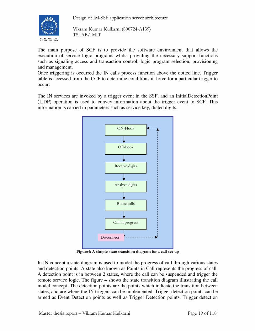
The IN services are invoked by a trigger event in the SSF, and an InitialDetectionPoint
(I_DP) operation is used to convey information about the trigger event to SCF. This
information is carried in parameters such as service key, dialed digits.
Figure4: A simple state transition diagram for a call set-up
In IN concept a state diagram is used to model the progress of call through various states
and detection points. A state also known as Points in Call represents the progress of call.
A detection point is in between 2 states, where the call can be suspended and trigger the
remote service logic. The figure 4 shows the state transition diagram illustrating the call
model concept. The detection points are the points which indicate the transition between
states, and are where the IN triggers can be implemented. Trigger detection points can be
armed as Event Detection points as well as Trigger Detection points. Trigger detection
ON-Hook
Off-hook
Receive digits
Analyze digits
Route calls
Call in progress
Disconnect

Design of IM-SSF application server architecture Vikram Kumar Kulkarni (800724-A139) TSLAB/IMIT
Master thesis report – Vikram Kumar Kulkarni Page 20 of 118
points is pre-armed, and waiting to be fired by call controlling software during normal
call processing. Event detection point is dynamically armed during a call set up by
instruction from SCF.
Customized Application Mobile Enhanced Logic defines intelligent network functionality
in GSM networks. Using CAMEL a GSM operator can provide operator specific services
to its subscribers. ETSI has started working on intelligent networking in GSM from 1994,
since then CMALE was evolved in 4 phases. The first phase is released in 1997, second
phase is released in 1998, and third phase is released in 1999 and now fourth is phase is
in use. The CAMEL phase 4 is specified in “3GPP 23.078 Release 5 Customised
Applications for Mobile network Enhanced Logic (CAMEL) Phase 4- Stage 2” [5].
The term intelligent networking is introduced by Bellcore in the USA in 1980s. Since
then the IN concept has gradually developed, and used worldwide in telecom networks.
Intelligent networking means separation of logic controlling services from the basic call
control function in existing telephone switches. The benefit of IN is separation of service
logic into a separately controllable entity, where services can be provided modified and
controlled by operator rather than switch manufacturers. This provides ability for
operators to develop operator specific services efficiently and without depending heavily
on switch manufacturers. Before IN concept is introduced the operators had to heavily
depended on switch manufacturers to provide competitive value added services to its
subscribers. Example of value added services are VPN, toll free, calling card.
Figure 5: CAMEL phase 4 architecture
GsmSSF
GMSC
HLR
GsmSCF
MAP
CAP

Design of IM-SSF application server architecture Vikram Kumar Kulkarni (800724-A139) TSLAB/IMIT
Master thesis report – Vikram Kumar Kulkarni Page 21 of 118
Figure 5 shows entities of CAMEL. The MSC handles the Call control function (CCF)
such as bearer control functions, and basic call processing. The bearer control function is
handles circuit switched transport connection including seizure and release of circuits.
The basic call processing means handling of address digits, call routing and may be call
forwarding. GsmSSF is hypothetical modeling device, models the call into a state
machines with states and events. GsmSSF is programmed in such a way that when a
particular event occurs, it can suspend the processing of calls and trigger service control
function for further instruction on how to precede the call. GsmSCF is a control pint
which controls the IN services, it host service provision logic, supporting structure to
communicate with SSF. SCF is referred as remote node because it is functionally external
to the normal call processing software.
The main purpose of SCF is to provide the software environment that allows the
execution of service logic programs whilst providing the necessary support functions
such as signaling access and transaction control, logic program selection, provisioning
and management. Once triggering is occurred the IN calls process function above the
dotted line. Trigger table is accessed from the CCF to determine conditions in force for a
particular trigger to occur. The IN services are invoked by a trigger event in the SSF, and
an InitialDetectionPoint (I_DP) operation is used to convey information about the trigger
event to SCF. This information is carried in parameters such as service key, dialed digits.
In CAMEL concept a state machine is used to model the progress of call through various
states and detection points. A state also known as Points in Call represents the progress of
call. A detection point is in between 2 states, where the call can be suspended and trigger
the remote service logic. The figure shows the state transition diagram illustrating the call
model concept. The detection points are the points which indicate the transition between
states, and are where the IN triggers can be implemented. Trigger detection points can be
armed as Event Detection points as well as Trigger Detection points. Trigger detection
points is pre-armed, and waiting to be fired by call controlling software during normal
call processing. Event detection point is dynamically armed during a call set up by
instruction from SCF.
In CAMEL the GsmSSF models the call control process in two halves; an origination half
and terminating half, namely the O_BCSM and the T_BCSM, represent the call. The
originating half (O_BCSM) monitors the call at incoming line, and terminating side
O_BCSM monitors the out going side. The T-BCSM has fewer states than the T-BCSM.
This is because T-BCSM is not invoked until the O-BCSM is some way into the
processing of call and it so exists for shorter period of time.

Design of IM-SSF application server architecture Vikram Kumar Kulkarni (800724-A139) TSLAB/IMIT
Master thesis report – Vikram Kumar Kulkarni Page 22 of 118
5. IM-SSF Internetworking In this section I will be describing the architectural issues of an IM-SSF. This description
is broadly divided into two parts. One is the IM-SSF internetworking with other
functional entities. And second one is description of CAMEL elements such as CAMEL
subscription information (CSI) and Basic Call State Machines (BCSMs).
5.1 Internetworking within IP multimedia subsystem The IM-SSF interacts with several functional entities to provide CAMEL services for the
subscriber.
5.1.1 Functional entities involved for CAMEL at IM registration
When S-CSCF downloads the subscription profile of MS requiring the CAMEL services
from HSS, it informs the IM-SSF about the MS registration over the ISC interface. Then
IM-SSF requests O-IM-CSI, D-IM-CSI, VT-IM-CSI data from the HSS over the Si
interface. This procedure is shown in figure 6.
Figure 6 - Functional architecture - CAMEL registration at IP Multimedia session
IM-SSF
S-CSCF
HSS
Cx Interface
Si
ISC Interface
Home network
MS
Design of IM-SSF application server architecture Vikram Kumar Kulkarni (800724-A139) TSLAB/IMIT
Master thesis report – Vikram Kumar Kulkarni Page 23 of 118
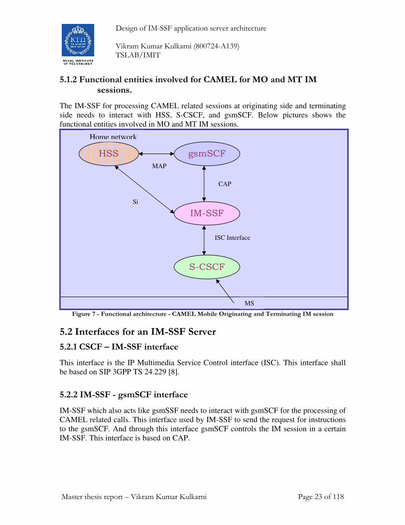
5.1.2 Functional entities involved for CAMEL for MO and MT IM sessions.
The IM-SSF for processing CAMEL related sessions at originating side and terminating
side needs to interact with HSS, S-CSCF, and gsmSCF. Below pictures shows the
functional entities involved in MO and MT IM sessions.
Figure 7 - Functional architecture - CAMEL Mobile Originating and Terminating IM session
5.2 Interfaces for an IM-SSF Server
5.2.1 CSCF – IM-SSF interface
This interface is the IP Multimedia Service Control interface (ISC). This interface shall
be based on SIP 3GPP TS 24.229 [8].
5.2.2 IM-SSF - gsmSCF interface
IM-SSF which also acts like gsmSSF needs to interact with gsmSCF for the processing of
CAMEL related calls. This interface used by IM-SSF to send the request for instructions
to the gsmSCF. And through this interface gsmSCF controls the IM session in a certain
IM-SSF. This interface is based on CAP.
gsmSCF
IM-SSF
S-CSCF
HSS
CAP
MAP
Si
ISC Interface
Home network
MS

Design of IM-SSF application server architecture Vikram Kumar Kulkarni (800724-A139) TSLAB/IMIT
Master thesis report – Vikram Kumar Kulkarni Page 24 of 118
5.2.3 HSS – IM-SSF interface
This interface is the Si interface and is used by IM-SSF to download the CAMEL related
subscriber data from HSS, e.g. IM-CSI. This interface is a MAP interface (as described
in 3GPP TS 29.002 )
5.3 Description of CAMEL Subscriber Data (Multimedia CAMEL Subscription Information (IM-CSI)) In this section, I will be describing the contents of the IP Multimedia CAMEL
Subscription Information. IM-CSI data are provisioned in the HSS for subscribers
having originating and/or terminating IP Multimedia CAMEL services. This information
is downloaded IM-SSF via the Si Interface. The IM-CSI data contains the O-IM-CSI,
D-IM-CSI, and VT-IM-CSI.
5.3.1 Originating IP Multimedia CAMEL Subscription Information (O-IM-CSI)
The O-IM-CSI consists of the following information elements.
5.3.1.1 gsmSCF Address
Address to be used to access the gsmSCF for a particular subscriber. The address is an
E.164 number to be used for routing.
5.3.1.2 Service Key
The Service Key identifies to the gsmSCF the service logic that should be applied.
5.3.1.3 Default Call Handling
The Default Call Handling indicates whether the IP Multimedia session should be
released or continued as requested in case of error in the IM-SSF to gsmSCF dialogue.
5.3.1.4 TDP List
The TDP List indicates on which detection point triggering shall take place. After
downloading the CSI the IM-SSF arms this TDP’s statically.
The following trigger detection points are possible: DP Collected_Info and DP
Route_Select_Failure.
5.3.1.5 CAMEL Capability Handling
CAMEL Capability Handling indicates the phase of CAMEL which is asked by the
gsmSCF for the service.

Design of IM-SSF application server architecture Vikram Kumar Kulkarni (800724-A139) TSLAB/IMIT
Master thesis report – Vikram Kumar Kulkarni Page 25 of 118
5.3.1.6 CSI Status
The CSI state indicates whether the O-IM-CSI is active or not.
5.3.1.7 Notification Flag
The notification flag indicates whether changes of the O-IM-CSI at HSS should trigger
the Notification on Change of Subscriber Data. Setting this flag to yes, the changes for
IM CSI at HSS will be updated at IM-SSF.
5.3.1.8 DP Criteria
The DP criteria indicate weather the IM-SSF shall request the gsmSCF for instructions.
5.3.2 Dialled Services IP Multimedia CAMEL Subscription Information (D-IM-CSI)
The D-IM-CSI consists of the following information elements.
5.3.2.1 gsmSCF Address
Address to be used to access the gsmSCF for a particular subscriber. The address shall be
an E.164 number to be used for routing.
5.3.2.2 Service Key
The Service Key identifies to the gsmSCF the service logic that should apply.
5.3.2.3 Default Call Handling
The Default Call Handling indicates whether the IP Multimedia session should be
released or continued as requested in case of error in the IM-SSF to gsmSCF dialogue.
5.3.2.4 CAMEL Capability Handling
CAMEL Capability Handling indicates the phase of CAMEL which is asked by the
gsmSCF for the service.
5.3.2.5 CSI Status
The CSI state indicates whether the D-IM-CSI is active or not.
5.3.2.6 Notification Flag
The notification flag indicates whether changes of the D-IM-CSI at HSS should trigger
the Notification on Change of Subscriber Data. Setting this flag to yes, the changes for
IM CSI at HSS will be updated at IM-SSF.
5.3.2.7 DP Criteria
The DP criteria indicate whether the IM-SSF shall request the gsmSCF for instructions.

Design of IM-SSF application server architecture Vikram Kumar Kulkarni (800724-A139) TSLAB/IMIT
Master thesis report – Vikram Kumar Kulkarni Page 26 of 118
5.3.3 Terminating IP Multimedia CAMEL Subscription Information (VT-IM-CSI)
5.3.3.1 gsmSCF Address
Address to be used to access the gsmSCF for a particular subscriber. The address shall be
an E.164 number to be used for routing.
5.3.3.2 Service Key
The Service Key identifies to the gsmSCF the service logic that should apply.
5.3.3.3 Default Call Handling
The Default Call Handling indicates whether the IP Multimedia session shall be released
or continued as requested in case of error in the IM-SSF to gsmSCF dialogue.
5.3.3.4 TDP List
The TDP List indicates on which detection point triggering shall take place. After
downloading the CSI the IM-SSF arms this TDP’s statically.
Following trigger detection points are allowed: DP Terminating_Attempt_Authorised,
DP T_Busy, and DP T_No_Answer.
5.3.3.5 CAMEL Capability Handling
CAMEL Capability Handling indicates the phase of CAMEL which is asked by the
gsmSCF for the service.
5.3.3.6 CSI Status
The CSI state indicates whether the VT-IM-CSI is active or not.
5.3.3.7 Notification Flag
The notification flag indicates whether changes of the VT-IM-CSI at HSS should trigger
the Notification on Change of Subscriber Data. Setting this flag to yes, the changes for
IM CSI at HSS will be updated at IM-SSF.
5.3.3.8 DP Criteria
The DP criteria indicate whether the IM-SSF shall request the gsmSCF for instructions.
5.3.4 Other CAMEL Data
5.3.4.1 gsmSCF address list for CSI
The gsmSCF address list for CSI indicates a list of gsmSCF addresses to which
Notification on Change of Subscriber Data is to be sent. In order to provide Notification
on Change of Subscriber Data to the IM-SSF, the IM-SSF address shall be included in the
gsmSCF address list.

Design of IM-SSF application server architecture Vikram Kumar Kulkarni (800724-A139) TSLAB/IMIT
Master thesis report – Vikram Kumar Kulkarni Page 27 of 118
The IM-SSF address is added to the gsmSCF address list for notification in the
HSS/HLR. The IM-SSF shall handle the receipt of the Notification on Change of
Subscriber Data using the same procedure as that of a gsmSCF.
5.4 Description of CAMEL State Models
In the IM Subsystem, calls are controlled by the Serving CSCF (S-CSCF) where a
subscriber is registered. A state model describes the call control behavior of an IM-SSF.
The purpose of basic call state model (BCSM) is to provide the gsmSCF with a
representative view of the call processing in the SSF. The SCF has no need for details of
the call processing implementation. It just needs to know enough to enable it to process
the service logic correctly.
5.4.2 Description of BCSM
The Basic Call State Model (BCSM) describes the handling of originating and
terminating calls in the form of a state machine.
This state machine consists of points in call (States in the machine) and detection points
(The point where the state machines transforms from one state to another state)
The IM-SSF is permitted to interact with gsmSCF only at detection points. And also
gsmSCF is permitted to interact with IM-SSF only at detection points.
Certain basic call events may be visible to the GSM Service Control Function (gsmSCF).
The DP's are the points in call at which these events are detected.
In the SSF the detection points are viewed as the points, which generally indicate the
transition between states. There are two types of detection points, one is trigger detection
points and another is event detection points.
A DP can be armed in order to notify the gsmSCF that the DP was encountered, and to
allow the gsmSCF to influence subsequent handling of the call. If the DP is not armed,
the processing entity continues the processing without gsmSCF involvement.
Three different types of DP’s are identified:
5.4.2.1 Trigger Detection Point - Request (TDP-R).
Trigger detection point is a detection point which is statically armed. When encountered
it initiates the CAMEL control relationship and there is no existing relationship due to the
same CSI.
5.4.2.2 Event Detection Point - Request (EDP-R).
Event detection points are a detection point which is dynamically armed within the
context of a CAMEL control relationship. When encountered the processing is suspended
at that DP and the IM-SSF waits for instructions from the gsmSCF.

Design of IM-SSF application server architecture Vikram Kumar Kulkarni (800724-A139) TSLAB/IMIT
Master thesis report – Vikram Kumar Kulkarni Page 28 of 118
5.4.2.3 Event Detection Point - Notification (EDP-N).
This detection point is dynamically armed within the context of a CAMEL control
relationship. Processing is not suspended when encountering the DP.
5.4.2.4 Arming of DP's
A DP ca is statically armed as a result of downloading CSI from the HSS.
• For mobile origination calls DP's are armed statically when IM-SSF downloads
the O-IM-CSI and D-IM-CSI.
• For mobile terminating call handling is statically armed in the IM-SSF as a result
of VT-IM-CSI data delivery from the HSS
• Static arming of DP’s in the IM-SSF occurs during the UE’s registration in the
IMS.
A DP is dynamically armed by the gsmSCF within the context of a CAMEL control
relationship as a result of IM-SSF receiving the RequestReportBCSMEvent operation.
• A Request Report BCSM Event information flow for a detection point for a leg
overwrites any previous Request Report BCSM Event information flow for that
detection point for that leg.
5.4.2.5 Disarming of DP's
A statically armed DP i.e. triggers detection points are disarmed when the IM CSI
data is withdrawn in the HSS.
The TDP’s are disarmed as follows
• If an armed EDP is met, then it is disarmed.
• If an EDP is met that causes the release of the related leg, then all EDP’s related
to that leg are disarmed.
• If a call session is released, then all EDPs related to that call session are disarmed.
• If an EDP is met, then other EDPS are disarmed, in accordance with the implicit
disarming rule table specified in TS 23.078 Rel-99 4
• If an EDP is armed, it can be explicitly disarmed by the gsmSCF by means of the
RequestReportBCSMEvent information flow.
5.4.3 Criteria
Criteria are the conditions that must be met in order for the IM-SSF to request
instructions from the gsmSCF. DP criteria are checked in the IM-SSF.
Criteria for originating DP’s are checked in the IM-SSF associated with the originating
UE’s S-CSCF. Criteria for terminating DP’s are checked in the IM-SSF associated with
the terminating UE’s S-CSCF.
When S-CSCF forwards the SIP message to the IM-SSF, the DP encountered is identified
based on the SIP message received from the S-CSCF. The mapping of SIP messages to
CAMEL IM-BCSM Detection Points is shown in tables

Design of IM-SSF application server architecture Vikram Kumar Kulkarni (800724-A139) TSLAB/IMIT
Master thesis report – Vikram Kumar Kulkarni Page 29 of 118
5.4.3.1 Criteria at Collected_Info
The HSS may store a list of up to 10 destination numbers and/or up to 3 number lengths.
This criterion may be defined to be either "enabling" or "inhibiting".
Triggering at DP Collected_Info is based on the destination number received from the
S-CSCF. The destination number received from the S-CSCF should not be modified
before conditional triggering check takes place.
If the destination number triggering criterion is enabling, then the IM-SSF may establish
a dialogue with the gsmSCF if:
• The destination number received from the S-CSCF is an ISDN number.
• The destination number matches one of the destination number strings defined in
the list.
• The length of the destination number matches one of the destination number
lengths defined in the list.
If the destination number triggering criterion is inhibiting, then the IM-SSF may establish
a dialogue with the gsmSCF if:
• The destination number received from the S-CSCF is not an ISDN number.
• The destination number does not match any of the destination number strings
defined in the list; and
• The length of the destination number does not match any of the destination
number lengths defined in the list.
5.4.3.2 Criteria at DP Analysed_Information
The following criteria are applicable for DP Analysed_Information:
Destination number triggering criterion: The HLR may store a list of up to 10 destination
numbers. This criterion does not match when the destination number received from the S-
CSCF or the gsmSCF is not an ISDN number.
Triggering at DP Analysed_Info shall be based on the destination number received in the
Connect operation from the gsmSCF during a Mobile Originating CAMEL Service. The
number comparison is described in detail in 3GPP TS 22.278.
5.4.3.3 Criteria at DP Route_Select_Failure
The HLR may store a list of up to 5 cause values for the route select failure.
The only criteria applicable for DP Route_Select_Failure is Release cause code.
The trigger criteria is met if the cause code received from the terminating party’s network
is equal to at least one of the cause codes in the trigger criteria list.
If an O-IM-BCSM was already invoked and there is a relationship with the gsmSCF at
that moment, then no additional relationship will be initiated.

Design of IM-SSF application server architecture Vikram Kumar Kulkarni (800724-A139) TSLAB/IMIT
Master thesis report – Vikram Kumar Kulkarni Page 30 of 118
5.4.3.4 Criteria at DP T_Busy and T_No_Answer
The HSS may store a list of up to 5 cause values.
The triggering is based on the release cause code received from terminating UE’s
P-CSCF.
The only criterion applicable for DP T_Busy and T_No_Answer is Release cause code.
The trigger criteria are met if the cause code received from the terminating UE’s P-CSCF
is equal to at least one of the cause codes in the trigger criteria list.
If trigger criteria are satisfied, then the corresponding Service Logic shall be invoked.
5.5 Originating CAMEL Basic Call State Model (O-IM-BCSM)
The O-IM-BCSM is used to model the behavior of an IM-SSF for an originating call.
When a DP is encountered, O-IM-BCSM processing is suspended at the DP and IM-SSF
indicates this to the gsmSCF if appropriate.
The figure 8 shows the originating CAMEL Basic Call State Model

Design of IM-SSF application server architecture Vikram Kumar Kulkarni (800724-A139) TSLAB/IMIT
Master thesis report – Vikram Kumar Kulkarni Page 31 of 118
O_Null & Authorise_Origination_Attempt_Collect_Info
O_Exception
Collected_Info
O_Answer
Basic Call transition
O_Disconnect
O_Active
Route_Select_Failure
O_Busy
O_No_Answer
O_Abandon
& Alerting
Routing
Analysed_Information
Analyse_Information
O_active_failure
invalid_information
O_routing_and_alerting_failure
Figure 8 - Originating CAMEL Basic Call State Model (O-IM-BCSM)
Detection Points and Points In Call components are shown in the BCSM diagrams.
The O-IM-BCSM consists of the following points in call
1. O_Null & Authorise_Origination_Attempt_Collect_Info
2. O_Analyse_Information
3. O_Routing and Alerting
4. O_Active
5. O_Exception
The O-IM-BCSM consists of the following detection points.
1. DP Collected_Info
2. DP Analysed_Information

Design of IM-SSF application server architecture Vikram Kumar Kulkarni (800724-A139) TSLAB/IMIT
Master thesis report – Vikram Kumar Kulkarni Page 32 of 118
3. DP Route_Select_Failure
4. DP O_Busy
5. DP O_No_Answer
6. DP O_Answer
7. DP O_Disconnect
8. DP O_Abandon
5.5.1 Description of detection points in O-IM-BCSM
The following table describes the DP’s in O-IM-BCSM.
Description of the O-IM-BCSM DP’s in an IM-SSF
CAMEL Detection
Point:
DP Type Description:
DP Collected_Info TDP-R Indication that the O-IM-CSI is analyzed
DP Analysed_Informat
ion
TDP-R Availability of routing address and nature of
address.
DP
Route_Select_Failure
TDP-R,
EDP-N,
EDP-R
Indication that the session establishment
failed.
DP O_Busy EDP-N,
EDP-R
Indication that:
• a busy indication is received from the
terminating party,
• a not reachable event is determined
upon a SIP error response.
DP O_No_Answer EDP-N,
EDP-R
Indication that:
• an application timer associated with
the O_No_Answer DP expires,
• a no answer event is determined upon
SIP a error response
DP O_Answer EDP-N,
EDP-R
Indication that the session is accepted and
answered by the terminating party.
DP O_Disconnect EDP-N,
EDP-R
A disconnect indication is received from the
originating party or from the terminating
party.
DP O_Abandon EDP-N,
EDP-R
Indication that a disconnect indication is
received from the originating party during
the session establishment procedure.
5.5.2 Description of Points in Call
In this section points in call for originating calls are described. These are states in the O-
IM-BCSM. The entry events, actions and exit events of the particular states are described.

Design of IM-SSF application server architecture Vikram Kumar Kulkarni (800724-A139) TSLAB/IMIT
Master thesis report – Vikram Kumar Kulkarni Page 33 of 118
5.5.2.1 O_Null & Authorise_Origination_Attempt_Collect_Info
Entry events: Events which can cause the state machine to enter into O_Null &
Authorise_Origination_Attempt_Collect_Info.
• Disconnection and clearing of a previous call (DP O_Disconnect) or default
handling of exceptions by O-IM-BCSM are completed.
• Abandon event is reported from Analysed_Information or Routing and Alerting
PIC.
• Exception event is reported.
Actions: The actions that can be taken by IM-SSF during this point in call
• Interface is idled.
• For the originating call SIP INVITE request message containing the dialed
number is received from MS.
• Information being analyzed e.g., O-IM-CSI is analyzed.
Exit events: The events which can cause to exit this state in the state machine
• Originating CSI is analyzed.
• An exception condition is encountered. For this PIC, if the call encounters one of
these exceptions during the PIC processing, the exception event is not visible
because there is no corresponding DP. Example exception condition: Calling
party abandons call.
5.5.2.2 Analysed_Information
Entry events:
• Originating CSI is analyzed. (DP Collected Info).
• New routing information is received when busy event (DP O_Busy), Route Select
Failure event (DP Route_Select_Failure), Not Reachable event (DP O_Busy) or
No Answer event (DP O_No_Answer) is reported from Routing and Alerting PIC.
• New routing information is received when Disconnect event is reported from
O_Active PIC.
Actions:
• Compare the called party number with the dialed services information.
Exit events:
• Availability of routing address and nature of address.
(DP Analysed_Information).
• An exception condition is encountered (e.g. wrong number) - this leads to the
O_Exception PIC.
• Calling party abandons the call- this leads to the O_Abandon DP.
5.5.2.3 O_Routing and Alerting
Entry events:
• Availability of routing address and nature of address (DP Analysed_Information).

Design of IM-SSF application server architecture Vikram Kumar Kulkarni (800724-A139) TSLAB/IMIT
Master thesis report – Vikram Kumar Kulkarni Page 34 of 118
Actions:
• Information is being analyzed and/or translated according to dialing plan to
determine routing address.
• Routing address being interpreted.
• Call is being processed by the terminating half BCSM. Continued processing of
SIP call session setup (e.g., ringing) is taking place. Waiting for indication from
terminating half BCSM that the call has been answered by terminating party.
Exit events:
• Indication from the terminating half BCSM that the call is accepted and answered
by terminating party (DP O_Answer).
• An exception condition is encountered - this leads to the O_Exception PIC.
• Calling party abandons the call- this leads to the O_Abandon DP.
• A busy indication is received from the terminating party - this leads to the
O_Busy DP.
• A not reachable indication is received from the terminating party - this leads to
the O_Busy DP.
• Attempt to select the route for the call fails - this leads to the
Route_Select_Failure DP.
• If the no reply timer expires and DP O_No_Answer is armed - this leads to the
O_No_Answer DP.
5.5.2.4 O_Active
Entry events:
• Indication from the terminating half BCSM that the call is accepted and answered
by the terminating party (DP O_Answer).
Actions:
• SIP session established between originating party and terminating party. - Call
release is awaited.
Exit events:
• A disconnection indication is received from the originating party, or received
from the terminating party via the terminating half BCSM. (DP - O_Disconnect).
• An exception condition is encountered.
5.5.2.5 O_Exception
Entry events:
• An exception condition is encountered. In addition to specific examples listed
above, exception events include any type of failure, which means that the normal
exit events for a PIC can not be met.
Actions:
• Default handling of the exception condition is being provided. This includes
general actions necessary to ensure that no resources remain inappropriately
allocated such as:
Design of IM-SSF application server architecture Vikram Kumar Kulkarni (800724-A139) TSLAB/IMIT
Master thesis report – Vikram Kumar Kulkarni Page 35 of 118
• If any relationship exists between the IM-SSF and the gsmSCF, the IM-SSF shall
send an error information flow closing the relationships and indicating that any
outstanding call handling instructions will not run to completion.
• Resources made available for setting up the SIP call session are released.
Exit events:
• Default handling of the exception condition by IM-SSF completed.
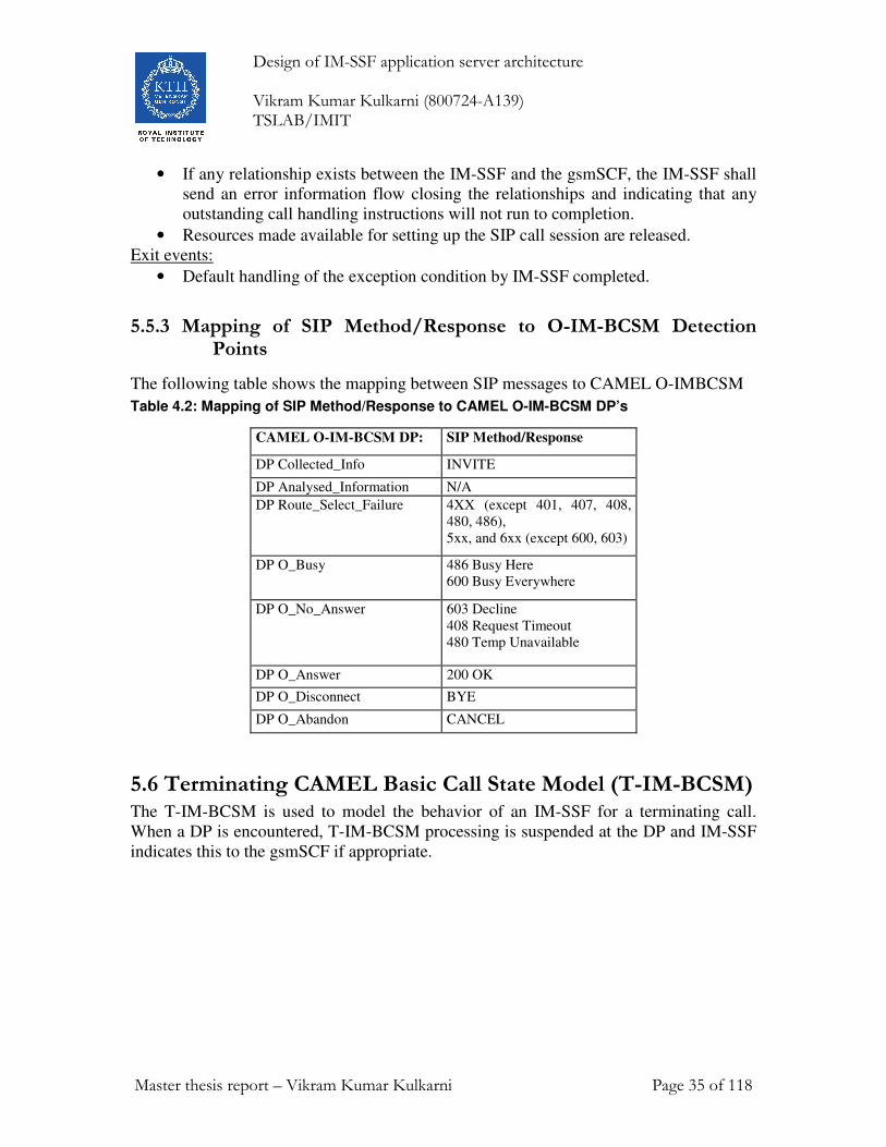
5.5.3 Mapping of SIP Method/Response to O-IM-BCSM Detection Points
The following table shows the mapping between SIP messages to CAMEL O-IMBCSM
Table 4.2: Mapping of SIP Method/Response to CAMEL O-IM-BCSM DP’s
CAMEL O-IM-BCSM DP: SIP Method/Response
DP Collected_Info INVITE
DP Analysed_Information N/A
DP Route_Select_Failure 4XX (except 401, 407, 408,
480, 486),
5xx, and 6xx (except 600, 603)
DP O_Busy 486 Busy Here
600 Busy Everywhere
DP O_No_Answer 603 Decline
408 Request Timeout
480 Temp Unavailable
DP O_Answer 200 OK
DP O_Disconnect BYE
DP O_Abandon CANCEL
5.6 Terminating CAMEL Basic Call State Model (T-IM-BCSM) The T-IM-BCSM is used to model the behavior of an IM-SSF for a terminating call.
When a DP is encountered, T-IM-BCSM processing is suspended at the DP and IM-SSF
indicates this to the gsmSCF if appropriate.

Design of IM-SSF application server architecture Vikram Kumar Kulkarni (800724-A139) TSLAB/IMIT
Master thesis report – Vikram Kumar Kulkarni Page 36 of 118
T_Null
Terminating Call Handling
T_Exception
T_Active
Terminating_Attempt_Authorised
T_Answer
Basic Call transition
T_Busy
T_No_Answer
T_Abandon
T_Disconnect
T_active_failure
T_call_handling_failure
Figure 9 - Terminating CAMEL Basic Call State Model (T-IM-BCSM)
The following table 4.3 defines the DP’s that apply to terminating calls.
Table 4.3: Description of T-IM-BCSM DP’s in the S-CSCF CAMEL DP: DP Type Description:
DP Terminating Attempt_
_Authorized
TDP-R Indication that the VT-IM-CSI is analyzed.
DP T_Busy TDP-R, EDP-N,
EDP-R
Indication that:
• a busy indication is received from the
terminating party,
• A not reachable event is determined (e.g.
terminating party is not currently registered).
DP T_No_Answer TDP-R, EDP-N,
EDP-R
Indication that an application timer associated with
the T_No_Answer DP expires.
DP O_Answer EDP-N, EDP-R Session is accepted and answered by terminating
party.
DP O_Disconnect EDP-N, EDP-R A disconnect indication is received from the
terminating party or from the originating party.
Design of IM-SSF application server architecture Vikram Kumar Kulkarni (800724-A139) TSLAB/IMIT
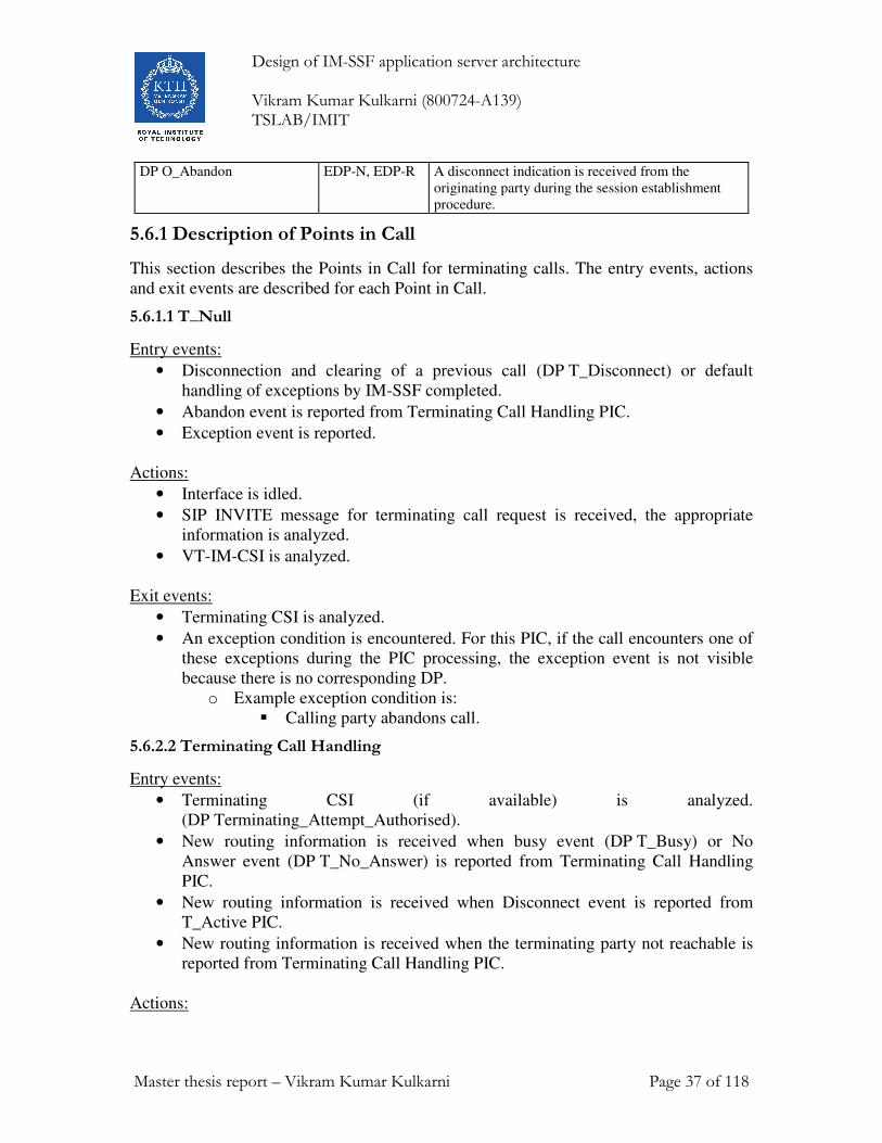
Master thesis report – Vikram Kumar Kulkarni Page 37 of 118
DP O_Abandon EDP-N, EDP-R A disconnect indication is received from the
originating party during the session establishment
procedure.
5.6.1 Description of Points in Call
This section describes the Points in Call for terminating calls. The entry events, actions
and exit events are described for each Point in Call.
5.6.1.1 T_Null
Entry events:
• Disconnection and clearing of a previous call (DP T_Disconnect) or default
handling of exceptions by IM-SSF completed.
• Abandon event is reported from Terminating Call Handling PIC.
• Exception event is reported.
Actions:
• Interface is idled.
• SIP INVITE message for terminating call request is received, the appropriate
information is analyzed.
• VT-IM-CSI is analyzed.
Exit events:
• Terminating CSI is analyzed.
• An exception condition is encountered. For this PIC, if the call encounters one of
these exceptions during the PIC processing, the exception event is not visible
because there is no corresponding DP.
o Example exception condition is:
� Calling party abandons call.
5.6.2.2 Terminating Call Handling
Entry events:
• Terminating CSI (if available) is analyzed.
(DP Terminating_Attempt_Authorised).
• New routing information is received when busy event (DP T_Busy) or No
Answer event (DP T_No_Answer) is reported from Terminating Call Handling
PIC.
• New routing information is received when Disconnect event is reported from
T_Active PIC.
• New routing information is received when the terminating party not reachable is
reported from Terminating Call Handling PIC.
Actions:

Design of IM-SSF application server architecture Vikram Kumar Kulkarni (800724-A139) TSLAB/IMIT
Master thesis report – Vikram Kumar Kulkarni Page 38 of 118
• Routing address and call type being interpreted. The next route or terminating
access is being selected.
• The terminating party is being alerted. Waiting for the call to be answered by
terminating party.
Exit events:
• Call is accepted and answered by terminating party.
• An exception condition is encountered - this leads to the T_Exception PIC.
Example exception conditions: the SIP call session request was not successful.
• Calling party abandons the call - this leads to the T_Abandon DP.
• A busy indication is received from the terminating party’s P-CSCF - this leads to
the T_Busy DP.
• Not reachable event detected from the terminating party’s P-CSCF - this leads to
the T_Busy DP.
• If no reply timer expires and DP T_No_Answer is armed - this leads to the
T_No_Answer DP.
3.6.2.3 T_Active
Entry events:
• Indication that the call is accepted and answered by the terminating party.
(DP T_Answer).
Actions:
• SIP session established between originating party and terminating party.
• Call release is awaited.
Exit events:
• A disconnection indication is received from the terminating party, or received
from the originating party via the originating half BCSM. (DP T_Disconnect).
• An exception condition is encountered. In addition to specific examples listed
above, exception events include any type of failure that means that the normal exit
events for a PIC can not be met.
5.6.2.4 T_Exception
Entry events:
• An exception condition is encountered. In addition to specific examples listed
above, exception events include any type of failure, which means that the normal
exit events for PIC cannot be met.
Actions:
• Default handling of the exception condition is being provided. This includes
general actions necessary to ensure that no resources remain inappropriately
allocated such as:
• If any relationship exists between the IM-SSF and the gsmSCF, the IM-SSF shall
send an error information flow closing the relationships and indicating that any
outstanding call handling instructions will not run to completion.

Design of IM-SSF application server architecture Vikram Kumar Kulkarni (800724-A139) TSLAB/IMIT
Master thesis report – Vikram Kumar Kulkarni Page 39 of 118
• Resources made available for setting up the SIP call session are released.
Exit events:
• Default handling of the exception condition by IM-SSF completed.
5.6.3 Mapping of SIP Method/Response to T-IM-BCSM Detection Points
The below table shows the mapping of SIP messages to CAMEL T-IM-BCSM DP’s
CAMEL T-IM-BCSM DP: SIP Method/Response
DP Terminating_Attempt__A
uthorised
INVITE
DP T_Busy 4XX (except 401, 407, 408, 480),
5xx, and 6xx (except 603)
DP T_No_Answer 603 Decline
408 Request Timeout
480 Temp Unavailable
DP T_Answer 200 OK
DP T_Disconnect BYE
DP T_Abandon CANCEL
6. Information Flows (Messages to and from the IM-SSF) In this section detailed description of the information flows used by IM-SSF
6.1 IM-SSF to gsmSCF information flows
6.1.1 Activity Test ack
6.1.1.1 Description
This IF is the response to the Activity Test.
6.1.1.2 Information Elements
This IF contains no information elements.
6.1.2 Apply Charging Report
6.1.2.1 Description
This IF is used by the IM-SSF to report to the gsmSCF the information requested in the
Apply Charging IF.

Design of IM-SSF application server architecture Vikram Kumar Kulkarni (800724-A139) TSLAB/IMIT
Master thesis report – Vikram Kumar Kulkarni Page 40 of 118
6.1.2.2 Information Elements
This message contains the following Information element
• Call Result
o Call Result contains another information flow called Time Duration
Charging Result. The Call Result Information element is described in
detail in 3GPP TS 23.278 v5.6.0 (2004-09)
6.1.3 Call Gap
6.1.3.1 Description
This IF is used to activate/modify/remove a call gap mechanism in the IM-SSF. The call
gap mechanism is used to reduce the rate at which specific service requests are sent to a
gsmSCF. A Call Gap operation can only be sent on an opened dialogue between a
gsmSCF and the IM-SSF.
It is possible to have several call gapping conditions applicable to the same IM-SSF (i.e.
each conditions were activated for a defined Service (identified by the service Key) by a
defined gsmSCF (identified by the gsmSCF Address).
6.1.3.2 Information Elements
This message contains the following Information element
• Gap Criteria
• Gap Indicators
• Control Type
• Gap Treatment
All the above information element are described in detail in 3GPP TS 23.278
6.1.4 Call Information Report
6.1.4.1 Description
This message is used to send specific call information for a single call to the gsmSCF as a
reply to gsmSCF previous Call Information Request.
6.1.4.2 Information Elements
This message contains the following Information element
• Requested Information List
• Leg ID
Design of IM-SSF application server architecture Vikram Kumar Kulkarni (800724-A139) TSLAB/IMIT
Master thesis report – Vikram Kumar Kulkarni Page 41 of 118
All these information element are described in detail in 3GPP TS 23.278
6.1.5 Event Report BCSM
6.1.5.1 Description
This message is used to notify the gsmSCF about a call related event (i.e. BCSM events
as answer and disconnected) which is
This Information flow is used to notify the gsmSCF of a call-related event (i.e. BCSM
events as answer and disconnect) which is previously requested by the gsmSCF.
GsmSCF can request for Event report BCSM using Request Report BCSM Event.
6.5.1.2 Information Elements
This message contains the following Information element
• Event type BCSM
• Event Specific Information BCSM
• Leg ID
• Misc Call Info
All these information element are described in detail in 3GPP TS 23.278
6.1.6 Initial DP
6.1.6.1 Description
This message is sent by the IM-SSF when a trigger is detected at a detection point (DP)
in the BCSM, to request instructions from the gsmSCF.
6.1.6.2 Information Elements
All these information element are described in detail in 3GPP TS 23.278
6.1.7 Specialized Resource Report
6.1.7.1 Description
This message is used to response to a Play Announcement message from gsmSCF when
the announcement is completed. And also with this message IM-SSF indicates that
announcement is completed
6.1.7.2 Information Elements
This message contains no information elements.

Design of IM-SSF application server architecture Vikram Kumar Kulkarni (800724-A139) TSLAB/IMIT
Master thesis report – Vikram Kumar Kulkarni Page 42 of 118
6.2 gsmSCF to IM-SSF information flows
6.2.1 Activity Test
6.2.1.1 Description
This Information Flow is used to check for the continued existence of a relationship
between the gsmSCF and IM-SSF. If the relationship is still in existence, then the
IM-SSF will respond. If no reply is received, then the gsmSCF will assume that the
IM-SSF has failed in some way and will take the appropriate action.
6.2.1.2 Information Elements
This message contains no information elements.
6.2.2 Apply Charging
6.2.2.1 Description
This IF is used for interacting from the gsmSCF with the IM-SSF charging mechanisms
to control the call duration.
6.2.2.2 Information Elements
This message contains the following Information element
• ACh Billing Charging Characteristics
• Party To Charge
All these information element are described in detail in 3GPP TS 23.278
6.2.3 Call Information Request
6.2.3.1 Description
This message is used to request the IM-SSF to record specific information about a single
call and report it back to the gsmSCF. The IM-SSF can report it with a Call Information
Report message.
6.2.3.2 Information Elements
This message contains the following Information element
• Requested Information Type List
• Leg ID
All these information element are described in detail in 3GPP TS 23.278
6.2.4 Cancel
6.2.4.1 Description Information Elements
This message is used to request the IM-SSF to cancel all Event Detection Points and
reports.

Design of IM-SSF application server architecture Vikram Kumar Kulkarni (800724-A139) TSLAB/IMIT
Master thesis report – Vikram Kumar Kulkarni Page 43 of 118
6.2.4.2 Information Elements
This message contains the following Information element
• All Requests
All these information element are described in detail in 3GPP TS 23.278
6.2.5 Connect
6.2.5.1 Description
This message is used to request the IM-SSF to perform the call processing actions to
route a call to a specific destination. The gsmSCF also provides calling party and existing
call set-up information, if required.
6.2.5.2 Information Elements
This message contains the following Information element
• Calling Party Category
• Destination Routing Address
• Destination Routing Address URL
• Original Called Party ID
• Original Called Party URL
• Redirecting Party ID
• Redirecting Party URL
All these information element are described in detail in 3GPP TS 23.278
6.2.6 Connect To Resource
6.2.6.1 Description
This message is used to connect a call from the IM-SSF to MRFC via S-CSCF.
6.2.6.2 Information Elements
This message contains no information elements for IMS.
6.2.7 Continue
6.2.7.1 Description
This message is used to request the IM-SSF to proceed with call processing. IM-SSF
resumes the processing at the DP at which it previously suspended call processing and
requests the gsmSCF for instructions.
After receiving Continue, the IM-SSF completes DP processing, and continues basic call
processing (i.e. proceeds to the next point in call in the BCSM) without substituting new
data from the gsmSCF.

Design of IM-SSF application server architecture Vikram Kumar Kulkarni (800724-A139) TSLAB/IMIT
Master thesis report – Vikram Kumar Kulkarni Page 44 of 118
6.2.7.2 Information Elements
This Information flow contains no information elements.
6.2.8 Continue With Argument
6.2.8.1 Description
This message is used to requests the IM-SSF to proceed with call processing. IM-SSF
resumes the processing at the DP at which it previously suspended call processing and
requested the gsmSCF for instructions.
After receiving Continue with Argument, the IM-SSF completes DP processing, and
continues basic call processing (i.e. proceeds to the next point in call in the BCSM) with
the modified call setup information as received from the gsmSCF.
6.2.8.2 Information Elements
This message contains the following Information element
• Calling Party Category
All these information element are described in detail in 3GPP TS 23.278
6.2.9 Disconnect Forward Connection
6.2.9.1 Description
This message is used to instruct the IM-SSF to disconnect with a MRFC, to which it has
previously established a connection using Connect to Resource Information Flow.
6.2.9.2 Information Elements
This IF contains no information elements.
6.2.10 Furnish Charging Information
6.2.10.1 Description
This message is used to request the IM-SSF to include call related information in the
CAMEL specific logical call record. The logical call record is created when FCI is
received and a logical call record for that leg does not exist. For modeling purposes the
logical call record is buffered in the IM-SSF. The IM-SSF completes logical call records
as defined in the SDL's. Once the logical call record is completed, then its free format
data is moved to the corresponding CDR and the logical call record is deleted.
The CSE can send multiple concatenated FCI's per leg for completion. The total
maximum of free format data is 160 octets per leg. The 160 octets may be sent in one or
more FCI operations. If there is non-completed free format data and new FCI operation(s)
is/are received to overwrite the non-completed data, then the non-completed data is
discarded and the gsmSCF can send another 160 octets per leg. The SDL’s of 3GPP
TS 23.078 Rel-99 [4] define when Logical CDR's are completed. After the completion

Design of IM-SSF application server architecture Vikram Kumar Kulkarni (800724-A139) TSLAB/IMIT
Master thesis report – Vikram Kumar Kulkarni Page 45 of 118
the gsmSCF can send another 160 octets of free format data in one or more FCI
operations for the called leg.
6.2.10.2 Information Elements
This message contains the following Information element
• FCI Billing Charging Characteristics
All these information element are described in detail in 3GPP TS 23.278
6.2.11 Release Call
6.2.11.1 Description
This message is used to tear down by the gsmSCF an existing call at any phase of the call
for all parties involved in the call.
6.2.11.2 Information Elements
This message contains the following Information element
• Release Cause
All these information element are described in detail in 3GPP TS 23.278
6.2.12 Request Report BCSM Event
6.2.12.1 Description
This message is used to instruct the IM-SSF to monitor for a call-related event, and then
send a notification back to the gsmSCF when the event is detected. When IM-SSF detects
the event it can sent notification using Event Report BCSM.
6.2.12.2 Information Elements
This message contains the following Information element
• BCSM Event
All these information element are described in detail in 3GPP TS 23.278
6.2.13 Reset Timer
6.2.13.1 Description
This message is used to refresh a timer.
6.2.13.2 Information Elements
This message contains the following Information element
• Timer Value
• Timer ID
All these information element are described in detail in 3GPP TS 23.278

Design of IM-SSF application server architecture Vikram Kumar Kulkarni (800724-A139) TSLAB/IMIT
Master thesis report – Vikram Kumar Kulkarni Page 46 of 118
6.3 gsmSCF – IM-SSF information flows for MRFC related operations In an IMS Core Network, the Multimedia Resource Function Controller (MRFC) is used
for providing specialized resource functions like playing announcements and tones.
Requests from the gsmSCF that requires a specialized resource function are sent to the
MRFC via the IM-SSF and S-CSCF using SIP signaling (as specified in the functional
requirements of the MRFC found in 3GPP TS 23.218 [5].)
This section contains the information flows descriptions between the gsmSCF and the
IM-SSF that are related to MRFC operations.
6.3.1 Cancel
6.3.1.1 Description
This Information Flow is used by the gsmSCF to request the IM-SSF to cancel a
correlated previous operation in the MRFC.
6.3.1.2 Information elements
This message contains the following Information element
• Invoke ID
All these information element are described in detail in 3GPP TS 23.278
6.3.2 Play Announcement
6.3.2.1 Description
This Information Flow is used to instruct IM-SSF to play an announcement or tone. And
required information for playing announcements or tones in the MRFC is also sent with
this IF.
6.3.3 Prompt And Collect User Information (received information)
6.3.3.1 Description
This Information Flow is sent from the gsmSCF to the IM-SSF and is used to interact
with a call party in order to collect information.
6.3.3.2 Information Elements
This message contains the following Information element
• Collected Info
• Information To Send
• Disconnect From IP Forbidden
All these information element are described in detail in 3GPP TS 23.278

Design of IM-SSF application server architecture Vikram Kumar Kulkarni (800724-A139) TSLAB/IMIT
Master thesis report – Vikram Kumar Kulkarni Page 47 of 118
6.3.4 Prompt And Collect User Information ack
6.3.4.1 Description
This Information Flow is used by the IM-SSF to indicate the result a Prompt and Collect
User Information IF to the gsmSCF.
6.3.4.2 Information Elements
This message contains the following Information element
• Digits Response
All these information element are described in detail in 3GPP TS 23.278
6.3.5 Specialized Resource Report
6.3.5.1 Description
This IF is used by the IM-SSF to response to a Play Announcement IF when the
announcement complete indication is set.
6.3.5.2 Information Elements
This IF contains no information elements.
6.4 IM-SSF to HSS information flows
6.4.1 Any Time Subscription Interrogation request
6.4.1.1 Description
This Information Flow is used by the IM-SSF to request and download subscription
information from the HSS/HLR.
For example, during UE's IMS registration S-CSCF will notify the IM-SSF over the ISC
interface. IM-SSF then shall send Any Time Subscription Interrogation request to HSS.
The IM-SSF shall also send the MAP ATSI request when a SIP INVITE message on a
MT session for an unregistered subscriber is received.
6.4.1.2 Information Elements
This message contains the following Information element
• gsmSCF Address
• Requested Info
• Subscriber Identity
All these information element are described in detail in 3GPP TS 23.278

Design of IM-SSF application server architecture Vikram Kumar Kulkarni (800724-A139) TSLAB/IMIT
Master thesis report – Vikram Kumar Kulkarni Page 48 of 118
6.4.2 Notify Subscriber Data Change ack
6.4.2.1 Description
This message is used to respond to the HSS/HLR’s notification of the change of
subscriber data.
6.4.2.2 Information Elements
This Information Flow contains no information elements.
6.5 HSS to IM-SSF information flows
6.5.1 Any Time Subscription Interrogation ack
6.5.1.1 Description
This message is used by the HSS/HLR to provide the requested subscriber’s IM-CSI data
to the IM-SSF.
6.5.1.2 Information Elements
This message contains the following Information element
• CAMEL Subscription Information
o Intern this information element contains the following elements
� O IM CSI
� D IM CSI
� VT IM CSI
All these information element are described in detail in 3GPP TS 23.278
6.5.2 Notify Subscriber Data Change
6.5.2.1. Description
This message is used by the HSS/HLR to notify to the IM-SSF of the change of
subscriber IM CSI data. This message is sent to IM-SSF at each time, when subscriber
IM CSI data is changed.
6.5.2.2 Information Elements
This message contains the following Information element
• IMSI
• MSISDN
• CAMEL Subscription Information
All these information element are described in detail in 3GPP TS 23.278

Design of IM-SSF application server architecture Vikram Kumar Kulkarni (800724-A139) TSLAB/IMIT
Master thesis report – Vikram Kumar Kulkarni Page 49 of 118
6.6 gsmSCF to HSS information flows Note: In my thesis work, I am not implementing these messages, as these messages are
not necessary for prototyping
6.6.1 Any Time Modification Request
6.6.1.1 Description
This message is used to modify information in the HSS at any time. This Information
flow from the gsmSCF to the HLR is specified in 3GPP TS 23.078 Rel-99 [4]. This
Information flow is also applied to the interface between the gsmSCF to the HSS.
6.6.1.2 Information Elements
Information elements for this message are described in 3GPP TS 23.078 Rel-99 [4].
6.6.2 Any Time Subscription Interrogation Request
6.6.2.1 Description
This Information flow is used by gsmSCF to request subscription information from the
HSS at any time. This Information flow from the gsmSCF to the HLR is specified in
3GPP TS 23.078 Rel-99 [4]. The IF is also applied to the interface between the gsmSCF
to the HSS.
6.6.2.2 Information Elements
Information elements for this message are described in 3GPP TS 23.078 Rel-99 [4].
6.6.3 Notify Subscriber Data Change response
6.6.3.1 Description
This Information flow is used by the gsmSCF to respond to the HSS of the change of
subscriber data notify. This information flow from the gsmSCF to the HLR is specified
in 3GPP TS 23.078 Rel-99 [4]. The information flow is also applied to the interface
between the gsmSCF to the HSS.
6.6.3.2 Information Elements
Information elements for this message are described in 3GPP TS 23.078 Rel-99 [4].
6.7 HSS to gsmSCF information flows
6.7.1 Any Time Modification ack
6.7.1.1 Description
This information flow is used by the HSS to provide the modified information to the
gsmSCF. This information flow from the HLR to the gsmSCF is specified in 3GPP

Design of IM-SSF application server architecture Vikram Kumar Kulkarni (800724-A139) TSLAB/IMIT
Master thesis report – Vikram Kumar Kulkarni Page 50 of 118
TS 23.078 Rel-99 [4]. The IF is also applied to the interface between the gsmSCF to the
HSS.
6.7.1.2 Information Elements
Information elements of any Time Modification ack is specified in 3GPP TS 23.078
Rel-99 [4]. Additionally the following IMS specific information elements are required:
• IM CSI
• VT IM CSI
• D IM CSI
All these additional information element are described in detail in 3GPP TS 23.278
6.7.2 Any Time Subscription Interrogation ack
6.7.2.1 Description
This information flow is used by the HSS to provide the requested subscription
information to the gsmSCF. This information flow from the HLR to the gsmSCF is
specified in 3GPP TS 23.078 Rel-99 [4]. The information flow is also applied to the
interface between the gsmSCF to the HSS.
6.7.2.2 Information Elements
The information elements of Any Time Subscription Interrogation ack is specified in
3GPP TS 23.078 Rel-99 [4]. Additionally the following IMS specific information
elements are required:
• Supported CAMEL Phases In HSS
• IM CSI
• VT IM CSI
• D IM CSI
These entire additional information elements are described in detail in 3GPP TS 23.278.
6.7.3 Notify Subscriber Data Change
6.7.3.1 Description
This information flow is used by the HSS to notify to the gsmSCF of the change of
subscriber data. This information flow is sent at each time subscriber data is changed.
The information flow from the HLR to the gsmSCF is specified in 3GPP TS 23.078
Rel-99 [4]. This information flow is also applied to the interface between the gsmSCF to
the HSS.
6.7.3.2 Information Elements
The information elements of Notify Subscriber Data Change are specified in 3GPP TS
23.078 Rel-99 [4]. Additionally the following IMS specific information elements are
required:

Design of IM-SSF application server architecture Vikram Kumar Kulkarni (800724-A139) TSLAB/IMIT
Master thesis report – Vikram Kumar Kulkarni Page 51 of 118
• Specific CSI Deleted List
These entire additional information elements are described in detail in 3GPP TS 23.278.

Design of IM-SSF application server architecture Vikram Kumar Kulkarni (800724-A139) TSLAB/IMIT
Master thesis report – Vikram Kumar Kulkarni Page 52 of 118
7. The design of the IM-SSF architecture
The main objective of this thesis work is to design the architecture of IM-SSF. The 3GPP
has given the functional architecture of IM-SSF in 3GPP 23.278 Release 5, but most of
the issues are left to the vendors to work on. The 3GPP standards have specified a very
rough functionality for the process of IM-SSF. It is for vendor to define rest of the
process required for an IM-SSF to work.
This chapter presents the overall functional architecture of IM-SSF. I have identified the
components of IM-SSF and their functionality, based on specification 3GPP 23.278
Release 5 [5]. In the standards the core functionality is given in an abstract level, based
on that I sketched the architecture of IM-SSF. I also defined some new components in the
IM-SSF. The details of process and procedures are explained in sub sequent sections.
Challenge
The challege is mapping the sip signalling to CAMLE application Part protocol (CAP
Protocol) The way to accomplish the challenge is
� Identifying what processes are already defined in standard, and understand theit
functionality is itself is a challeng. Because IM-SSF is a very complex node as so
the process are more complex.
� To define new processes required for a functional IM-SSF, that works in
conjunction with already defined processes in standard.
First of all, I would like to give an introduction of high level architecture of IM-SSF.
Basically IM-SSF consists of several process (I have identified 14 processes), and several
state machines (they are also a kind processes; I have identified 6 kinds of state
machines). All these processes that I identified can only provide the basic functionality of
IM-SSF. As specified in the limitations (§ section 1.2), I am not investigating OAM, load
balancing, statistics.
7.1 The IM – SSF architecture given in standards In 3GPP 23.278 Release 5, only SDL diagrams are given. And there is no explanation
given about the purpose and task of each process. Based on the deep examination of all
the SDL diagrams given in 3GPP 23.278 Release 5, I am sketching this architecture. In
this section I am going to explain the purpose of each process and the task of each
process in more detail.
The overview of IM-SSF is shown in figure 10 Basically IM-SSF interfaces SIP to CAP,
it has ISC (SIP based) interface towards S-CSCF, and CAP Interface towards GsmSCF.
So IM-SSF has Some SIP components to handle SIP messages, some CAMEL
components to handle CAP messages. Some processes will model originating calls with
the help of state machines, the fourth kind of processes model the terminating calls using
a state machine.

Design of IM-SSF application server architecture Vikram Kumar Kulkarni (800724-A139) TSLAB/IMIT
Master thesis report – Vikram Kumar Kulkarni Page 53 of 118
In the standard the basic functionality of IM-SSF is described. Obviously the real IM-SSF
needs much more functionality. The IM-SSF is one of the most complex nodes in the 3G
IMS.
The following components are identified from the standard
1. Process Register_IM_SSF
2. O-IM-BCSM (Originating IP multimedia Basic Call State Model)
3. T-IM-BCSM (Terminating IP multimedia Basic Call State Model)
4. Process MO_IM_SSF (Mobile Originating IP multimedia Service Switching
Function)
5. Process MT_IM_SSF (Mobile Terminating IP multimedia Service Switching
Function)
6. Process imcnSSF (IP Multimedia Core Network Service Switching Function)
Figure 10: Architecture given in standard
7.1.1. O-IM-BCSM (Originating IP multimedia Basic Call State Model)
The O-IM-BCSM is used to model the behavior of an IM-SSF for an originating call.
When a DP is encountered, O-IM-BCSM processing is suspended at the DP and IM-SSF
indicates this to the gsmSCF if appropriate. This is also called as call view state machine.
S-CSCF
ImcnSSF
MO_IM_SSF
Register_
IM_SSF
Mobile
Station
Terminating-
CSCF
HSS
MRFC
ISC Interface
gsmSCF
SIP SIP
Cx Interface
DIAMETER
Si Interface
(MAP)
Mr Interface (SIP)
Internal Interfaces
IM-SSF
MT_IM_SSF
IMS
CAP Interface

Design of IM-SSF application server architecture Vikram Kumar Kulkarni (800724-A139) TSLAB/IMIT
Master thesis report – Vikram Kumar Kulkarni Page 54 of 118
7.1.2. Process MO_IM_SSF
Process MO_IM_SSF is responsible for processing the originating CAMEL related
sessions. Based on the incoming SIP messages from S-CFCF and incoming messages
from gsmSCF (through imcnSSF) it will run the O-IM-BCSM state machine. It has
complete control over the O-IM-BCSM state machine. This process explained in detail in
§ section 7.7.3. This process sends and receives the SIP equivalent messages from SIP
UAS (through SIP parser and originating leg controller). And also sends CAP equivalent
internal message through imcnSSF. So SIP to CAP interfacing is done in this process.
7.1.3 T-IM-BCSM (Terminating IP multimedia Basic Call State Model)
The T-IM-BCSM is used to model the behavior of an IM-SSF for a terminating call.
When a DP is encountered, T-IM-BCSM processing is suspended at the DP and IM-SSF
indicates this to the gsmSCF if appropriate.
7.1.4 Process MT_IM_SSF (Mobile Terminating IP multimedia Service Switching Function)
Process MT_IM_SSF is responsible for processing the terminating CAMEL related
sessions. Based on the incoming SIP messages from S-CFCF and incoming messages
from gsmSCF (through imcnSSF) it will run the T-IM-BCSM state machine. It has
complete control over the T-IM-BCSM state machine. This process sends and receives
the SIP equivalent messages controller). And also sends CAP equivalent internal message
through imcnSSF. So SIP to CAP interfacing is done in this process.
7.1.5 Process imcnSSF
ImcnSSF takes the role of gsmSSF. imcnSSF internally interfaces with processes
MO_IM_SSF and MT_IM_SSF. imcnSSF is a quite complex process. It has CAP
interface with gsmSCF. And so it builds and parses the CAP messages, the entire
relationship of IM-SSF with gsmSCF is managed by this process.
7.1.6 Process Register_IM_SSF
Process Register_IM_SSF manages the IM-CS1 and it is responsible for downloading the
IM-CSI from the HSS, updating the IM-CSI, and deleting the IM-CSI. This process
explained in detail in § section 7.5
7.2. IM-SSF architecture designed by me The architecture of IM-SSF given in standards is incomplete, Infact it just gives a core
and basic architecture. As stated earlier a lot issues are left to vendor. Now I am
designing a functional IM-SSF. For that I am defining some more processes that will
work in conjunction with processes already defined in standards. The processes defined
in standards together with processes defined by me will make a functional IM-SSF. The
architecture of IM-SSF designed by me is shown in figure 11.

Design of IM-SSF application server architecture Vikram Kumar Kulkarni (800724-A139) TSLAB/IMIT
Master thesis report – Vikram Kumar Kulkarni Page 55 of 118
I am defining the following processes which I think are required for the basic
functionality of IM-SSF. Trigger manager
1. IL-O-IM-BCSM (Incoming Leg Originating IP multimedia Basic Call State
Model)
2. Process IL-MO-IM-SSF (Incoming Leg Mobile Originating IP multimedia
Service Switching Function)
3. OL-O-IM-BCSM (Outgoing Leg Originating IP multimedia Basic Call State
Model)
4. Process OL-MO-IM-SSF (Outgoing Leg Mobile Originating IP multimedia
Service Switching Function)
5. IL-T-IM-BCSM (Incoming Leg Terminating IP Multimedia Basic Call State
Model)
6. Process IL-MT-IM-SSF (Incoming Leg Mobile Terminating IP multimedia
Service Switching Function)
7. OL-T-IM-BCSM (Outgoing Leg Terminating IP multimedia Basic Call State
Model)
8. Process OL-MT-IM-SSF (Incoming Leg Mobile Terminating IP multimedia
Service Switching Function)
9. Leg Controller for originating BCSM
10. Leg controller for terminating BCSM
11. User Agent Server (UAS)
12. User Agent Client (UAC)
13. Message parser.

Design of IM-SSF application server architecture Vikram Kumar Kulkarni (800724-A139) TSLAB/IMIT
Master thesis report – Vikram Kumar Kulkarni Page 56 of 118
Figure 11: IM-SSF Architecture Designed by me.
Conceptually I have categorized all these processes into five categories
1. Processes that interfaces to SIP
a. User Agent Server (UAS)
b. User Agent Client (UAC)
c. Message parser.
2. Processes handling registration and subscription information
a. Process Register_IM_SSF
b. Trigger manager
S-CSCF
ImcnSSF
MO_IM_SSF
Register_
IM_SSF
Mobile
Station
Terminating-
CSCF
HSS
MRFC Trigger
manager
ISC Interface
gsmSCF
SIP SIP
Cx Interface
DIAMETER
Si Interface
(MAP)
Mr Interface (SIP)
Internal Interfaces
IM-SSF
Originating Leg
Controller
SIP
UAC
Terminating Leg
Controller
IL-MO-
IM-SSF
OL-MO-
IM-SSF
SIP
UAS
Message Parser
IL-MT-
IM-SSF
MT_IM_SSF
intBCSM intBCSM
OL-MT-
IM-SSF
IMS
CAP Interface

Design of IM-SSF application server architecture Vikram Kumar Kulkarni (800724-A139) TSLAB/IMIT
Master thesis report – Vikram Kumar Kulkarni Page 57 of 118
3. Processes handling originating users
a. Originating Leg Controller
b. O-IM-BCSM (Originating IP multimedia Basic Call State Model)
c. Process MO_IM_SSF (Mobile Originating IP multimedia Service Switching
Function)
d. IL-O-IM-BCSM (Incoming Leg Originating IP multimedia Basic Call State
Model)
e. Process IL-MO-IM-SSF (Incoming Leg Mobile Originating IP multimedia
Service Switching Function)
f. OL-O-IM-BCSM (Outgoing Leg Originating IP multimedia Basic Call State
Model)
g. Process OL-MO-IM-SSF (Outgoing Leg Mobile Originating IP multimedia
Service Switching Function)
4. Processes handling terminating users
a. T-IM-BCSM (Terminating IP multimedia Basic Call State Model)
b. Process MT_IM_SSF (Mobile Terminating IP multimedia Service Switching
Function)
c. IL-T-IM-BCSM (Incoming Leg Terminating IP Multimedia Basic Call State
Model)
d. Process IL-MT-IM-SSF (Incoming Leg Mobile Terminating IP multimedia
Service Switching Function)
e. OL-T-IM-BCSM (Outgoing Leg Terminating IP multimedia Basic Call State
Model)
f. Process OL-MT-IM-SSF (Incoming Leg Mobile Terminating IP multimedia
Service Switching Function)
g. Leg controller for terminating BCSM
5. Processes that interfaces to CAP
a. Process imcnSSF (IP Multimedia Core Network Service Switching Function)
7.3 The components of IM-SSF Application Server. In this section I am giving the descriptions of all components of IM-SSF, that I
mentioned in § section 7.1 & 7.2. All the components are depicted in figure 11.
7.3.1 Processes that interfaces to SIP
7.3.1.1 SIP UAS (SIP User Agent Server)
It is simply a SIP user agent server, as defined in rfc 3261. User agent server application
runs in the user equipment. A user agent server is a logical entity that generates a
response to a SIP request. The response accepts, rejects, or redirects the request. This role
lasts only for the duration of that transaction. In other words, if a piece of software
responds to a request, it acts as a UAS for the duration of that transaction. If it generates a
request later, it assumes the role of a user agent client for the processing of that
transaction.

Design of IM-SSF application server architecture Vikram Kumar Kulkarni (800724-A139) TSLAB/IMIT
Master thesis report – Vikram Kumar Kulkarni Page 58 of 118
7.3.1.2 SIP UAC (SIP User Agent Client)
It is simply a SIP user gent client, as defined in rfc 3261. User agent client application
runs in the user equipment. A user agent client is a logical entity that creates a new
request, and then uses the client transaction state machinery to end it. The role of UAC
lasts only for the duration of that transaction. In other words, if a piece of software
initiates a request, it acts as a UAC for the duration of that transaction. If it receives a
request later, it assumes the role of a user agent server for the processing of that
transaction.
7.3.1.3 SIP parser
This module is designed to parse the SIP messages to internal messages i.e., to an internal
data type. It is positioned just above to the SIP UAS and SIP UAC, as shown in figure 11.
The mapped internal data type will be forwarded to the appropriate upward processes
(They are Originating leg controller, Terminating Leg Controller and Register_IM_SSF).
This module explained in detail in § section 7.4
7.3.2 Processes handling registration and subscription information
7.3.2.2 Trigger manager
This module is responsible for managing the IM-CSI data in IM-SSF and arming of the
trigger detection points in the O-IM-BCSM.
7.3.3 Processes handling originating users
7.3.3.1 Originating Leg Controller
This module is designed to manage the call legs and co relation between incoming and
outgoing leg corresponding to same session. It is responsible for managing call legs of a
call, where the originating user is home network subscriber. This module is described in
detail in § section 7.7.1
7.3.3.4 IL-O-IM-BCSM (Incoming Leg Originating IP multimedia Basic Call State Model)
IM-SSF acts as a back to back user agent (B2BUA). There is one call running between
originating party and IM-SSF. And another call running between the IM-SSF and
terminating party. This BCSM is used model the call between the originating party and
IM-SSF. It is also called as incoming leg view state machine.
7.3.3.5 Process IL_MO_IM_SSF (Incoming Leg Mobile Originating IP multimedia Service Switching Function)
This process will manage and run the IL-O-IM-BCSM (Incoming Leg Originating IP
multimedia Basic Call State Model).
Design of IM-SSF application server architecture Vikram Kumar Kulkarni (800724-A139) TSLAB/IMIT
Master thesis report – Vikram Kumar Kulkarni Page 59 of 118
7.3.3.6 OL-O-IM-BCSM (Outgoing Leg Originating IP multimedia Basic Call State Model)
This BCSM is used model the call between the IM-SSF and terminating party. This
BCSM cannot trigger the gsmSCF directly, how ever it can request O-IM-BCSM to
trigger at gsmSCF. It is also called as outgoing leg view state machine.
7.3.3.7 Process OL_MO_IM_SSF (Outgoing Leg Mobile Originating IP multimedia Service Switching Function)
This process will manage and run the OL-O-IM-BCSM (Incoming Leg Originating IP
multimedia Basic Call State Model).
7.3.4 Processes handling terminating users
In this section terminating user refers to a terminating user who is a home network
subscriber.
7.3.4.3 IL-T-IM-BCSM (Incoming Leg Terminating IP Multimedia Basic Call State Model)
IM-SSF acts as a back to back user agent (B2BUA). There is one call running between
originating party and IM-SSF. And another call running between the IM-SSF and
terminating party. This BCSM is used model the call between the originating party and
IM-SSF.
7.3.4.4 Process IL-MT-IM-SSF (Incoming Leg Mobile Terminating IP multimedia Service Switching Function)
This process will manage and run the IL-T-IM-BCSM (Incoming Leg Terminating IP
multimedia Basic Call State Model).
7.3.4.5 OL-T-IM-BCSM (Outgoing Leg Terminating IP multimedia Basic Call State Model)
This BCSM is used model the call between the IM-SSF and terminating party.
7.3.4.6 Process OL-MT-IM-SSF (Outgoing Leg Mobile Terminating IP multimedia Service Switching Function)
This process will manage and run the OL-T-IM-BCSM (Outgoing Leg Terminating IP
multimedia Basic Call State Model).
7.3.4.7 Leg controller for terminating BCSM
This module is designed to manage the call legs and co relation between incoming and
outgoing leg corresponding to same session. It is responsible for managing call legs,
where the terminating user home network subscriber.
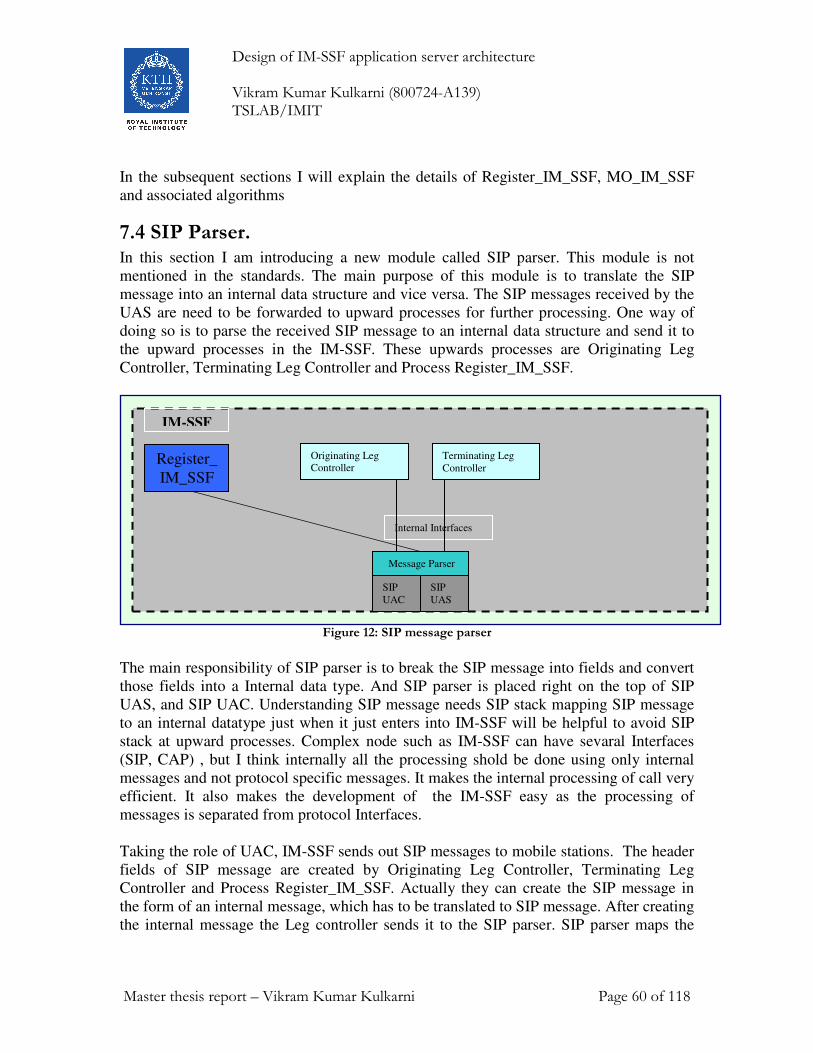
Design of IM-SSF application server architecture Vikram Kumar Kulkarni (800724-A139) TSLAB/IMIT
Master thesis report – Vikram Kumar Kulkarni Page 60 of 118
In the subsequent sections I will explain the details of Register_IM_SSF, MO_IM_SSF
and associated algorithms
7.4 SIP Parser. In this section I am introducing a new module called SIP parser. This module is not
mentioned in the standards. The main purpose of this module is to translate the SIP
message into an internal data structure and vice versa. The SIP messages received by the
UAS are need to be forwarded to upward processes for further processing. One way of
doing so is to parse the received SIP message to an internal data structure and send it to
the upward processes in the IM-SSF. These upwards processes are Originating Leg
Controller, Terminating Leg Controller and Process Register_IM_SSF.
Figure 12: SIP message parser
The main responsibility of SIP parser is to break the SIP message into fields and convert
those fields into a Internal data type. And SIP parser is placed right on the top of SIP
UAS, and SIP UAC. Understanding SIP message needs SIP stack mapping SIP message
to an internal datatype just when it just enters into IM-SSF will be helpful to avoid SIP
stack at upward processes. Complex node such as IM-SSF can have sevaral Interfaces
(SIP, CAP) , but I think internally all the processing shold be done using only internal
messages and not protocol specific messages. It makes the internal processing of call very
efficient. It also makes the development of the IM-SSF easy as the processing of
messages is separated from protocol Interfaces.
Taking the role of UAC, IM-SSF sends out SIP messages to mobile stations. The header
fields of SIP message are created by Originating Leg Controller, Terminating Leg
Controller and Process Register_IM_SSF. Actually they can create the SIP message in
the form of an internal message, which has to be translated to SIP message. After creating
the internal message the Leg controller sends it to the SIP parser. SIP parser maps the
Register_
IM_SSF
Internal Interfaces
IM-SSF
Originating Leg
Controller
SIP
UAC
Terminating Leg
Controller
SIP
UAS
Message Parser

Design of IM-SSF application server architecture Vikram Kumar Kulkarni (800724-A139) TSLAB/IMIT
Master thesis report – Vikram Kumar Kulkarni Page 61 of 118
internal message to the SIP message and sends it to the UAC. The UAC sends out the SIP
message to mobile station.
The SIP parser is shown above in figure 12. It has interfaces with Originating Leg
Controller, Terminating Leg Controller, Register_IM_SSF, UAC and UAS.
The functions of SIP parser
• It parses the SIP message received from the UAS to an internal data structure as
shown below.
• After parsing the SIP message to an internal message i.e. intXXX, it forwards the
intXXX to an upward processes, those upwards processes are Originating Leg
Controller, Terminating leg Controller and Register_IM_SSF.
- It forwards the intREGISTER message to Register_IM_SSF
- It forwards the intXXX message to originating leg controller if
� If the home subscriber is originating user
- It forwards the intXXX message to originating leg controller if
� If the home subscriber is terminating user.
• It receives the intXXX message from upward processes. It parses the received
intXXX message to SIP XXX message and sends it to the UAC.
- intREGISTER to SIP REGISTER
- intINVITE to SIP INVITE
- intRINGING to 180 RINGING
- intOK to SIP 200 OK
- intBYE to SIP BYE
- intXXX to SIP XXX
7.5 SIP registration into IM-SSF During the IMS registration process of the UE at S-CSCF, if the subscriber is provisioned
with CAMEL subscription information (CSI), the S-CSCF retrieves the filter criteria for
the IM-SSF from the HSS.
The HSS includes the IMSI data for the subscriber within the Service Information element
of the filter criteria for IM-SSF. The IMSI shall be used for querying the HSS/HLR for
CAMEL Subscription Information data via a MAP interface.

Design of IM-SSF application server architecture Vikram Kumar Kulkarni (800724-A139) TSLAB/IMIT
Master thesis report – Vikram Kumar Kulkarni Page 62 of 118
Figure 13 – IP Multimedia registration
The entities involved in the registration process at IM-SSF are
• Process Register_IM_SSF in IM-SSF
• HSS
• S-CSCF
The data format for the CAMEL subscription information is determined by the CAMEL
service provider. The CSI is transparent to S-CSCF. S-CSCF do not process, analyze, or
evaluate the CSI. A recommended data format for IM-CSI is presented in the section §
7.6.1
If a registration request matches the filter criteria of the IM-SSF, the S-CSCF informs the
IM-SSF by sending the SIP REGISTER message to IM-SSF.
The process and the procedures involved in registration and de-registration of IM-SSF:
• Process Register_IM_SSF;
• Procedure CAMEL_IMCN_Register;
• Procedure CAMEL_IMCN_DeRegister.
S-CSCF
ImcnSSF
Register_
IM_SSF
Mobile
Station
Terminating-
CSCF
HSS
ISC Interface
gsmSCF
SIP SIP
Cx Interface
DIAMETER
Si Interface
(MAP)
IM-SSF
IMS
CAP Interface

Design of IM-SSF application server architecture Vikram Kumar Kulkarni (800724-A139) TSLAB/IMIT
Master thesis report – Vikram Kumar Kulkarni Page 63 of 118
7.5.1 Process Register_IM_SSF
This process is responsible for handling registration and de-registration in the IM-SSF. It
processes the SIP REGISTER request. When IM-SSF receives the SIP REGISTER
request, it shall be forwarded to the ‘Register_IM_SSF’ process.
Algorithm:
1. Receive the SIP REGISTER request
2. If the Timer Expires > 0 than, it invokes the CAMEL_IMCN_Register
3. If the Timer Expires < 0 than, it invokes the CAMEL_IMCN_DeRegister
The corresponding SDL diagram is shown in 3GPP TS 23.278 #Figure 4.9
7.5.1.1 Procedure CAMEL_IMCN_Register
This procedure is used by Process ‘Register_IM_SSF’ to download the IM-CSI to the
IM-SSF.
Algorithm:
1. Check the subscriber profile is downloaded
2. If it is already downloaded then, send an 200 OK to the S-CSCF
3. If not, send an ATSI_query to HSS to request IM CSI
4. Wait for the response from the HSS
5. If the response is ATSI_Ack (i.e. the requested IM CSI is sent along with
ATSI_Ack) then store the IM CSI and send a 200 OK t the S-CSCF.
6. If the response is ATSI_negative Response, if error information available, then
make a new query.
7. In case no Error information is available, send an SIP 606 Not Acceptable to the
S-CSCF.
The corresponding SDL diagram is shown in 3GPP TS 23.278 #Figure 4.10
7.5.1.2 Procedure CAMEL_IMCN_DeRegister
This procedure is used by Process ‘Register_IM_SSF’ to delete the IM-CSI from the IM-
SSF.
Algorithm
1. Check the subscriber IM-CSI data available.
2. If not, proceed to step 4.
3. If available, delete the IM-CSI data.
4. Send SIP 200 OK to the S-CSCF.
The corresponding SDL diagram is shown in 3GPP TS 23.278 #Figure 4.11
7.5.2. Handling of notify subscriber data change
When the HSS updates the CSI for a subscriber in the IP Multimedia CN subsystem, the
HSS shall send a Notify Subscriber Data Change message to the IM-SSF if:
• The IM CSI data is marked with the Notification Flag
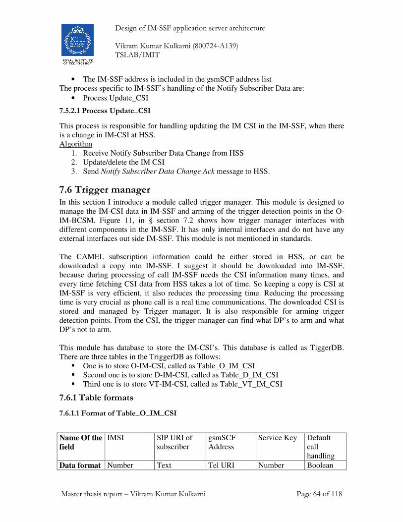
Design of IM-SSF application server architecture Vikram Kumar Kulkarni (800724-A139) TSLAB/IMIT
Master thesis report – Vikram Kumar Kulkarni Page 64 of 118
• The IM-SSF address is included in the gsmSCF address list
The process specific to IM-SSF’s handling of the Notify Subscriber Data are:
• Process Update_CSI
7.5.2.1 Process Update_CSI
This process is responsible for handling updating the IM CSI in the IM-SSF, when there
is a change in IM-CSI at HSS.
Algorithm
1. Receive Notify Subscriber Data Change from HSS
2. Update/delete the IM CSI
3. Send Notify Subscriber Data Change Ack message to HSS.
7.6 Trigger manager In this section I introduce a module called trigger manager. This module is designed to
manage the IM-CSI data in IM-SSF and arming of the trigger detection points in the O-
IM-BCSM. Figure 11, in § section 7.2 shows how trigger manager interfaces with
different components in the IM-SSF. It has only internal interfaces and do not have any
external interfaces out side IM-SSF. This module is not mentioned in standards.
The CAMEL subscription information could be either stored in HSS, or can be
downloaded a copy into IM-SSF. I suggest it should be downloaded into IM-SSF,
because during processing of call IM-SSF needs the CSI information many times, and
every time fetching CSI data from HSS takes a lot of time. So keeping a copy is CSI at
IM-SSF is very efficient, it also reduces the processing time. Reducing the processing
time is very crucial as phone call is a real time communications. The downloaded CSI is
stored and managed by Trigger manager. It is also responsible for arming trigger
detection points. From the CSI, the trigger manager can find what DP’s to arm and what
DP’s not to arm.
This module has database to store the IM-CSI’s. This database is called as TiggerDB.
There are three tables in the TriggerDB as follows:
� One is to store O-IM-CSI, called as Table_O_IM_CSI
� Second one is to store D-IM-CSI, called as Table_D_IM_CSI
� Third one is to store VT-IM-CSI, called as Table_VT_IM_CSI
7.6.1 Table formats
7.6.1.1 Format of Table_O_IM_CSI
Name Of the
field
IMSI SIP URI of
subscriber
gsmSCF
Address
Service Key Default
call
handling
Data format Number Text Tel URI Number Boolean
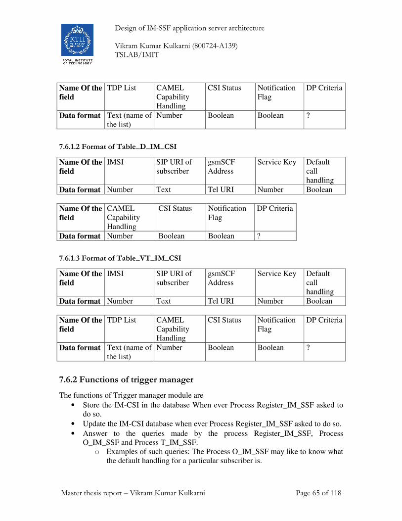
Design of IM-SSF application server architecture Vikram Kumar Kulkarni (800724-A139) TSLAB/IMIT
Master thesis report – Vikram Kumar Kulkarni Page 65 of 118
Name Of the
field
TDP List CAMEL
Capability
Handling
CSI Status Notification
Flag
DP Criteria
Data format Text (name of
the list)
Number Boolean Boolean ?
7.6.1.2 Format of Table_D_IM_CSI
Name Of the
field
IMSI SIP URI of
subscriber
gsmSCF
Address
Service Key Default
call
handling
Data format Number Text Tel URI Number Boolean
Name Of the
field
CAMEL
Capability
Handling
CSI Status Notification
Flag
DP Criteria
Data format Number Boolean Boolean ?
7.6.1.3 Format of Table_VT_IM_CSI
Name Of the
field
IMSI SIP URI of
subscriber
gsmSCF
Address
Service Key Default
call
handling
Data format Number Text Tel URI Number Boolean
Name Of the
field
TDP List CAMEL
Capability
Handling
CSI Status Notification
Flag
DP Criteria
Data format Text (name of
the list)
Number Boolean Boolean ?
7.6.2 Functions of trigger manager
The functions of Trigger manager module are
• Store the IM-CSI in the database When ever Process Register_IM_SSF asked to
do so.
• Update the IM-CSI database when ever Process Register_IM_SSF asked to do so.
• Answer to the queries made by the process Register_IM_SSF, Process
O_IM_SSF and Process T_IM_SSF.
o Examples of such queries: The Process O_IM_SSF may like to know what
the default handling for a particular subscriber is.
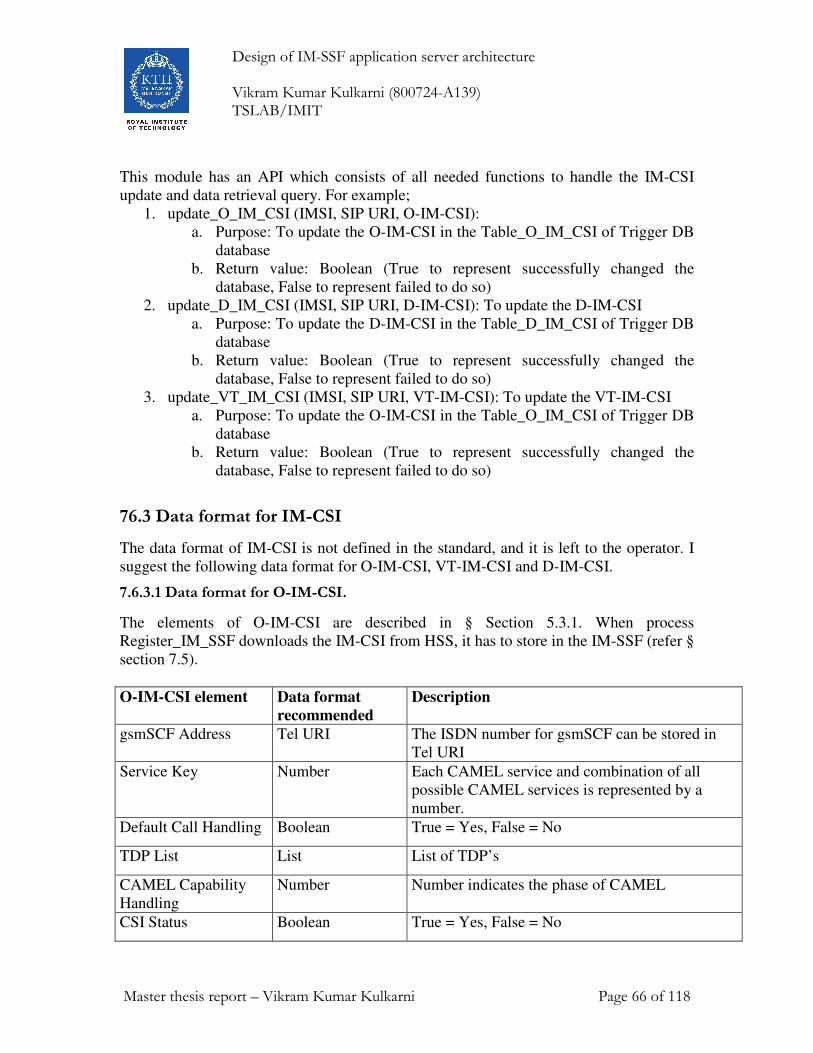
Design of IM-SSF application server architecture Vikram Kumar Kulkarni (800724-A139) TSLAB/IMIT
Master thesis report – Vikram Kumar Kulkarni Page 66 of 118
This module has an API which consists of all needed functions to handle the IM-CSI
update and data retrieval query. For example;
1. update_O_IM_CSI (IMSI, SIP URI, O-IM-CSI):
a. Purpose: To update the O-IM-CSI in the Table_O_IM_CSI of Trigger DB
database
b. Return value: Boolean (True to represent successfully changed the
database, False to represent failed to do so)
2. update_D_IM_CSI (IMSI, SIP URI, D-IM-CSI): To update the D-IM-CSI
a. Purpose: To update the D-IM-CSI in the Table_D_IM_CSI of Trigger DB
database
b. Return value: Boolean (True to represent successfully changed the
database, False to represent failed to do so)
3. update_VT_IM_CSI (IMSI, SIP URI, VT-IM-CSI): To update the VT-IM-CSI
a. Purpose: To update the O-IM-CSI in the Table_O_IM_CSI of Trigger DB
database
b. Return value: Boolean (True to represent successfully changed the
database, False to represent failed to do so)
76.3 Data format for IM-CSI
The data format of IM-CSI is not defined in the standard, and it is left to the operator. I
suggest the following data format for O-IM-CSI, VT-IM-CSI and D-IM-CSI.
7.6.3.1 Data format for O-IM-CSI.
The elements of O-IM-CSI are described in § Section 5.3.1. When process
Register_IM_SSF downloads the IM-CSI from HSS, it has to store in the IM-SSF (refer §
section 7.5).
O-IM-CSI element Data format
recommended
Description
gsmSCF Address Tel URI The ISDN number for gsmSCF can be stored in
Tel URI
Service Key Number Each CAMEL service and combination of all
possible CAMEL services is represented by a
number.
Default Call Handling Boolean True = Yes, False = No
TDP List List List of TDP’s
CAMEL Capability
Handling
Number Number indicates the phase of CAMEL
CSI Status Boolean True = Yes, False = No

Design of IM-SSF application server architecture Vikram Kumar Kulkarni (800724-A139) TSLAB/IMIT
Master thesis report – Vikram Kumar Kulkarni Page 67 of 118
Notification Flag Boolean True = Yes, False = No
DP Criteria Pointer Pointer to the list of services
7.6.3.2 Data format for D-IM-CSI
The elements of O-IM-CSI are described in § Section 5.3.2. When process
Register_IM_SSF downloads the IM-CSI, it has to store in the IM-SSF (refer § section
7.5).
D-IM-CSI element Data format
recommended
Description
gsmSCF Address Tel URI The ISDN number for gsmSCF can be stored in
Tel URI
Service Key Number Each CAMEL service and combination of all
possible CAMEL services is represented by a
number.
Default Call Handling Boolean True = Yes, False = No
CAMEL Capability
Handling
Number Number indicates the phase of CAMEL
CSI Status Boolean True = Yes, False = No
Notification Flag Boolean True = Yes, False = No
DP Criteria Pointer Pointer to list of services
7.6.3.3 Data format for VT-IM-CSI.
The elements of O-IM-CSI are described in § Section 5.3.1. When process
Register_IM_SSF downloads the IM-CSI it has to store in the IM-SSF.
VT-IM-CSI element Data format
recommended
Description
gsmSCF Address Tel URI The ISDN number for gsmSCF can be stored in
Tel URI
Service Key Number Each CAMEL service and combination of all
possible CAMEL services is represented by a
number.
Default Call Handling Boolean True = Yes, False = No
TDP List List List of TDP’s
CAMEL Capability Number Number indicates the phase of CAMEL

Design of IM-SSF application server architecture Vikram Kumar Kulkarni (800724-A139) TSLAB/IMIT
Master thesis report – Vikram Kumar Kulkarni Page 68 of 118
Handling
CSI Status Boolean True = Yes, False = No
Notification Flag Boolean True = Yes, False = No
DP Criteria Pointer Pointer to list of services
It is Assumed that the gsmSCF is seen as single entity from IM-SSF point of so, therefore
he gsmSCF address is a single Tel URI. (A limitation of this work)
7.7. Handling of mobile originated calls in the IM-SSF In the IM-SSF the originating calls are handled by the process Originating Leg controller.
The following entities are involved in the processing of originating calls.
1. Originating Leg Controller
This module is designed to manage the call legs and co relation between incoming and
outgoing leg corresponding to same session. It is responsible for managing call legs,
where the originating user is this network subscriber. This module is described in detail
in § section 7.6.1
2. O-IM-BCSM (Originating IP multimedia Basic Call State Model) The O-IM-BCSM is used to model the behavior of an IM-SSF for an originating call.
When a DP is encountered, O-IM-BCSM processing is suspended at the DP and IM-SSF
indicates this to the gsmSCF if appropriate. This is also called as call view state machine.
It is explained in detail in § section 5.5
3 Process MO_IM_SSF
Process MO_IM_SSF is responsible for processing the originating CAMEL related
sessions. Based on the incoming SIP messages from S-CFCF and incoming messages
from gsmSCF (through imcnSSF) it will run the O-IM-BCSM state machine. It has
complete control over the O-IM-BCSM state machine. This process explained in detail in
§ section 7.7.3. This process sends and receives the SIP equivalent messages from SIP
UAS (through SIP parser and originating leg controller). And also sends CAP equivalent
internal message through imcnSSF. So SIP to CAP interfacing is done in this process.
4 IL-O-IM-BCSM (Incoming Leg Originating IP multimedia Basic Call State
Model)
IM-SSF acts as a back to back user agent (B2BUA). There is one call running between
originating party and IM-SSF. And another call running between the IM-SSF and
terminating party. This BCSM is used model the call between the originating party and
IM-SSF. This BCSM cannot trigger the gsmSCF directly, how ever it can request O-IM-
BCSM to trigger at gsmSCF. It is also called as incoming leg view state machine.

Design of IM-SSF application server architecture Vikram Kumar Kulkarni (800724-A139) TSLAB/IMIT
Master thesis report – Vikram Kumar Kulkarni Page 69 of 118
5 Process IL_MO_IM_SSF (Incoming Leg Mobile Originating IP multimedia
Service Switching Function)
This process will manage and run the IL-O-IM-BCSM (Incoming Leg Originating IP
multimedia Basic Call State Model).
6 OL-O-IM-BCSM (Outgoing Leg Originating IP multimedia Basic Call State
Model)
This BCSM is used model the call between the IM-SSF and terminating party. This
BCSM cannot trigger the gsmSCF directly, how ever it can request O-IM-BCSM to
trigger at gsmSCF. It is also called as outgoing leg view state machine.
7 Process OL_MO_IM_SSF (Outgoing Leg Mobile Originating IP multimedia
Service Switching Function)
This process will manage and run the OL-O-IM-BCSM (Incoming Leg Originating IP
multimedia Basic Call State Model).
The O-IM-BCSM, IL-O-IM-BCSM and OL-O-IM-BCSM are similar in structure and
similar in functionality. In the same way MO_IM_SSF, OL_MO_IM_SSF and
IL_MO_IM_SSF are similar in structure and functionality.
In this sub section I will describe the functionality of Leg controller, process
MO_IM_SSF and the working of state machines (Call view, Incoming leg view and
Outgoing leg view). The state machine O-IM-BCSM is already described in detail in §
section 5.5.
7.7.1 Originating Leg Controller
IM-SSF acts as a SIP B2BUA user agent. It has a two different call legs one with
originating party and another with terminating party. IM-SSF co-relates between these
two call legs.
Originating leg controller handles the call legs of originating home network subscriber. It
is shown in figure 14. This module has interfaces with SIP parser (Refer § section 7.4).
Through SIP parser it can communicate with User agent server (UAS) and User agent
client (UAC) as shown in figure 14. It also has interfaces with IL_MO_IM_SSF,
OL_MO_IM_SSF and MO_IM_SSF. It has only internal interfaces and do not have any
external interfaces out side IM-SSF.
The state machines are created and managed by process XX-IM-MO-SSF and proces
XX-TM-IM-SSF. The state machine that models incomming leg is managed by ... , out
going leg by ... and the whole call is modelled by ... To model a single originating call,
there will be 3 XX-IM-Mo-ssf processed are created, and they will be destoyed once the
call is ended. So there must be some nuatral process that creates these process when a
new call is started, and destroyes these process. Hence I define a new process called Leg

Design of IM-SSF application server architecture Vikram Kumar Kulkarni (800724-A139) TSLAB/IMIT
Master thesis report – Vikram Kumar Kulkarni Page 70 of 118
controller. XX-IM-MO-SSF processes belonging to same call are needed to communicate
with each other during the processing of call, to inform their status to upper process i.e.
MO-IM-SSF. One of way doing so is by communicating through Leg controller.
The functions of originating leg controller
1. It co-relates the incoming and outgoing call legs.
2. When Originating Leg Controller receives SIP INVITE message (internal message) it
instantiates the IL-O-IM-BCSM, IL_MO_IM_SSF, O-IM-BCSM, MO_IM_SSF, OL-
O-IM-BCSM and OL_MO_IM_SSF.
3. As described in § section 7.4 The SIP parser forwards any SIP message (internal
message) of originating subscriber to Originating leg controller. The Originating Leg
Controller receives the internal message and forwards it to the either
IL_MO_IM_SSF or OL_MO_IM_SSF. If the SIP message is sent by originating
party, then it is forwarded to the IL_MO_IM_SSF, if the SIP message from the
terminating party then it is forwarded to the OL_MO_IM_SSF.
Figure 14: Originating Leg Controller
This module is designed to manage the call legs and co relation between incoming and
outgoing leg corresponding to same session. A simple model for co-relating incoming
and outgoing leg is proposed.
imcnSSF
MO_IM_SSF
Internal Interfaces
IM-SSF
Originating Leg
Controller
SIP
UAC
IL-MO-
IM-SSF
OL-MO-
IM-SSF
SIP
UAS
Message Parser
intBCSM

Design of IM-SSF application server architecture Vikram Kumar Kulkarni (800724-A139) TSLAB/IMIT
Master thesis report – Vikram Kumar Kulkarni Page 71 of 118
A model for co-relating incoming and outgoing leg
1. We have a unique Call ID for incoming led
2. And another unique Call ID for out going leg
3. A local reference serial number (O_Ref_num) is generated (Starting from 1)
which is incremented by 1 for each new SIP message received by IM-SSF. Map
this reference number with Call ID’s
4. By Mapping those call ID's together with local reference number, we can co-
relate between incoming and out going legs. Incoming leg calls ID, outgoing leg
call Id and reference number are stored in a database to maintain the co-relation
related information. This database called as LegDB.
The format of the OLegDB database shall be:
Name of the
field
O_SIP_URI
(Originating
party URI)
T_SIP_URI
(Terminating
party URI)
O_CallID
(Call Id of
originating
leg)
T_CallID
(Call Id of
originating
leg)
O_Ref_num
(A serial
reference
number that
is generated
in IM-SSF)
Data format Text Text Text Text Number
Log contorller can be very overloaded during times of peak traffic. Leg controller handles
XX-IM-MO-SSF processes for all originating calls, which could be some hundreds of
calls per second. So, I though it is better to have another separate Inteface for such
comminication between IL-MO-IM-SSF, OL-MO-IM-SSF, MO-IM-SSF. For that
communication we defined a new interface called intBCSM. It is responsible
communication between IL-MO-IM-SSF, OL-MO-IM-SSF, MO-IM-SSF processes.
This interface is simple in it’s functionality, mainly aimed to reduce load from Leg
controller process.
7.7.2 The working of state machines (O-IM-BCSM, IL-O-IM-BCSM and OL-O-IM-BCSM)
IM-SSF acts as a back to back user agent. It terminates the call of originating user and
creates a new call leg towards the terminating user. So there will be two call legs i.e. one
is incoming leg and outgoing leg at the IM-SSF. The Originating Leg controller
correlates these two call legs as described in § section 7.7.1.
To model the whole end to end call by an O-IM-BCSM it is needed to model the
incoming half (incoming leg view) of the call and out going half (Outgoing leg view) of
the call. Based on these two models and on the top of these two models, the entire call
can be modeled and it is called as call view (Call view).

Design of IM-SSF application server architecture Vikram Kumar Kulkarni (800724-A139) TSLAB/IMIT
Master thesis report – Vikram Kumar Kulkarni Page 72 of 118
Figure 15: Call view and Leg view state machines.
So there will be a BCSM for incoming leg view, a BCSM for outgoing leg view and one
another BCSM for call view as shown in the figure 15. These three BCSM are
synchronized.
These BCSM’s are co-related and they need to communicate each other. For that purpose
I introduce a new internal interface as intBCSM. The BCSM do not communicate directly
O-IM-BCSM
IL-O-IM-
BCSM
OL-O-IM-
BCSM
MO_IM_SSF
IL_MO_IM_SS OL_MO_IM_SSF
intBCSM
UAS UAE
SIP perser
Originating Leg
Controller
IM-SSF

Design of IM-SSF application server architecture Vikram Kumar Kulkarni (800724-A139) TSLAB/IMIT
Master thesis report – Vikram Kumar Kulkarni Page 73 of 118
to each other. But the MO_IM_SSF (MO_IM_SSF, IL MO_IM_SSF, and
OL_MO_IM_SSF) processes will communicate each other through intBCSM interface
and adjust the BCSM. In the following section I will describe how these BCSM are acts
together within IM-SSF using a simple traffic case. And this description is a high level
description.
Some observations:
- The process IL_MO_IM_SSF and O_MO_IM_SSF do not have any interface
with the process imcnSSF, and they do not communicate with gsmSCF.
- But MO_IM_SSF have interface with the process imcnSSF, and it communicates
with the gsmSCF. Since the process MO_IM_SSF handles the call view, it is
responsible (and it can only) to trigger at gsmSCF via imcnSSF.
7.7.2.1 A simple CAMEL traffic case.
In this section I am describing how the call view and leg view BCSM changes (how state
machine runs) during a CAMEL call through IM-SSF.
A detailed traffic case involving CAMEL IM session is described in §section 10. The
reader is suggested to have a look at § section 10 and figure 18. Now I am explaining
what happens inside IM-SSF for the same traffic case. In this section I am just
considering the traffic flows between the S-CSCF, IM-SSF and gsmSCF. The emphasis is
given how three state machines are changes there states when the IM-SSF receives SIP
INVITE, 180 RINGING, 200 OK, BYE.
Consider a simple call between Alice and Bob involving the following SIP messages.
• SIP INVITE
• SIP 180 RINGING
• SIP 200 OK
• SIP BYE.
An incoming SIP message to the IM-SSF is received by the User Agent Server. The SIP
message will be sent to SIP parser. The SIP parser maps the SIP message to intXXX
message. The intXXX message is then forwarded to the upwards processes.
- It forwards the intXXX message to originating leg controller if
� If the home subscriber is originating user
- It forwards the intXXX message to terminating leg controller if
� If the home subscriber is terminating user.
For the detailed functionality of the SIP parser refer to § section 7.4.
When a process wants to send out SIP message, they will send an internal message (data
structure) as an input SIP parser. The SIP parser maps the internal message to SIP
Design of IM-SSF application server architecture Vikram Kumar Kulkarni (800724-A139) TSLAB/IMIT
Master thesis report – Vikram Kumar Kulkarni Page 74 of 118
message and sends it to the SIP UAC. The user agent client builds the SIP message and
sends out from IM-SSF.
SIP INVITE:
When the caller initiates the call, the SIP INVITE is received by UAS. UAS forwards the
SIP INVITE message to SIP parser. The SIP parser maps the SIP INVITE to intXXX and
sends it to the Originating Leg Controller. As described in § section 7.7.1, the Originating
Leg Controller passes the intINVITE to the IL_MO_IM_SSF. The IL_MO_IM_SSF sets
the IL-O-IM-BCSM to the state “O_Null & Authorise_Origination_Attempt_Collect_
Info”. It sends intINVITE message to the MO_IM_SSF through the interface intBCSM.
After receiving the intINVITE message the MO_IM_SSF sets the O-IM-BCSM to the
state “O_Null & Authorise_Origination_Attempt_Collect_Info”. The O-IM-BCSM then
sends the intINVITE to the OL_MO_IM_SSF through intBCSM. The OL_MO_IM_SSF
then sets the OL-O-IM-BCSM to the state “O_Null &
Authorise_Origination_Attempt_Collect _Info”.
Hence the order of the SIP INVITE traversal through BCSM is
Incoming leg view BCSM −> Call view BCSM −> Outgoing leg view BCSM.
The OL_MO_IM_SSF then sends the intINVITE to SIP parser through Originating Leg
Controller. The Originating leg controller co-relates the call legs ands sends the
intINVITE message to SIP parser. The SIP parser maps the intINVITE to SIP INVITE
and sends it to the SIP UAC. The SIP UAC builds the SIP INVITE and sends out to the
terminating user.
SIP 180 RINGING:
When the callee responds with SIP 180 RINGING, nothing really happens as there is no
corresponding DP in the O-IM-BCSM. It is first received by the UAS. UAS forwards the
SIP 180 RINGING to SIP parser. The SIP parser maps the SIP 180 RINGING to
intRINGING and sends it to Originating Leg Controller. The Originating Leg Controller
sends the intINVITE to the process OL_MO_IM_SSF. Since there is no corresponding
DP it just forwards the message to the process MO_IM_SSF. MO_IM_SSF then forwards
the intRINGING to the process IL_MO_IM_SSF. The process IL_MO_IM_SSF does
nothing except forwarding it to SIP parser. The SIP parser forms the SIP 180 RINGING
and sends it to the UAC. And UAC builds the SIP 180 RINGING message and sends it
out to the calling party.
Hence the order of the SIP 180 RINGING traversal through BCSM is
Outgoing leg view BCSM −> Call view BCSM −> Incoming leg view BCSM.
SIP 200 OK

Design of IM-SSF application server architecture Vikram Kumar Kulkarni (800724-A139) TSLAB/IMIT
Master thesis report – Vikram Kumar Kulkarni Page 75 of 118
When the user answers the call, the callee sends SIP 200 OK message. The SIP 200 OK
message is first received by the UAS. The UAS then sends SIP 200 OK to SIP parser.
The SIP parser parses the SIP 200 OK message to intOK. The SIP parser sends the SIP
200 OK message to Originating Leg Controller. Since the 200 OK coming from
terminating party it forwards the int200 OK to the process OL_MO_IM_SSF. The
OL_MO_IM_SSF sets the OL-O-IM-BCSM to the state “O-Active”. The process
OL_MO_IM_SSF then sends the internal message i.e., intOK to the process
MO_IM_SSF. The process MO_IM_SSF sets the O-IM-BCSM to the state “O-Active”
and sends intOK message to IL_MO_IM_SSF. The IL_MO_IM_SSF sets the IL-O-IM-
BCMS state to “O-Active” and sends the intOK message to SIP parser through
Originating Leg Controller. The SIP parser maps the intOK to SIP 200 OK and sends it to
the SIP UAC. The UAC builds the SIP 200 OK message and sends it out to the calling
party.
Hence the order of the SIP 200 OK traversal within IM-SSF is
Outgoing leg view BCSM −> Call view BCSM −> Incoming leg view BCSM.
SIP BYE
When the user ends the call (Lets suppose the terminating party), the callee sends SIP
BYE message. The SIP BYE message is first received by the UAS. The UAS then sends
SIP BYE message to process SIP parser. The SIP parser maps the SIP BYE to intBYE
message and sends it to the Originating Leg Controller. The Originating Leg Controller
sends the intBYE to the process OL_MO_IM_SSF. The OL_MO_IM_SSF sets the OL-
O-IM-BCSM to the state “O_Disconnect”. The process OL_MO_IM_SSF then sends the
internal message i.e., intBYE to the process MO_IM_SSF. The process MO_IM_SSF
sets the O-IM-BCSM to the state “O-Disconnect”. The process MO_IM_SSF sends
intBYE message to the process IL_MO_IM_SSF, which sets the IL-O-IM-BCSM to the
state “O_Disconnect” and sends intBYE message to the SIP parser through Originating
Leg Controller. The SIP parser maps the intBYE to SIP BYE and sends it to the UAC.
The UAC builds the SIP BYE message and sends it out to the calling party. With this
session is terminated.
7.7.3 Process MO_IM_SSF
The most important process of which handles the originating calls in IM-SSF is
MO_IM_SSF. It handles the state machine O-IM-BCSM, which is a call view state
machine. So I am explaining in a great detail of this process in this section.
It is responsible for
1. Running O_IM_BCSM
2. Communicating with imcnSSF regarding originating session processing
3. Maintaining timers: Tb, TInvite and Tack.

Design of IM-SSF application server architecture Vikram Kumar Kulkarni (800724-A139) TSLAB/IMIT
Master thesis report – Vikram Kumar Kulkarni Page 76 of 118
4. It has internal interfaces with Trigger manager, Originating Leg controller,
imcnSSF and intBCSM.
The SDL diagram of handling originating sessions within IM-SSF is shown below.
Figure 16: Process MO_IM_SSF
The process and the procedures specific to the handling mobile originated calls are
� Process MO_IM_SSF;
� Procedure CAMEL_IMCN_MO_O_IM_CSI_INIT;
� Procedure CAMEL_IMCN_MO_D_IM_CSI_INIT;
� Procedure CAMEL_IMCN_MO_CANCEL;
� Procedure CAMEL_IMCN_MO_ANSWER;
� Procedure CAMEL_IMCN_MO_UNSUCCESSFUL;
� Procedure CAMEL_IMCN_MO_DISC1;
� Procedure CAMEL_IMCN_MO_DISC2;
� Procedure CAMEL_OCH_CTR.
ImcnSSF
MO_IM_SSF
Internal Interfaces
IM-SSF
Originating Leg
Controller
SIP
UAC
IL-MO-
IM-SSF
OL-MO-
IM-SSF
SIP
UAS
Message Parser
intBCSM
gsmSCF
CAP Interface
IMS
O-IM-
BCSM

Design of IM-SSF application server architecture Vikram Kumar Kulkarni (800724-A139) TSLAB/IMIT
Master thesis report – Vikram Kumar Kulkarni Page 77 of 118
The process MO_IM_SSF is responsible for handling the originating session in the IM-
SSF. It uses the above mentioned procedures. All the procedures mentioned above are
invoked by MO_IM_SSF.
The MO_IM_SSF have an interface to the process imcnSSF. The MO_IM-SSF
communicates with gsmSCF through imcnSSF.
The messages to MO_IM_SSF from imcnSSF are
� Int_Error
� Int_Continue
� Int_Continue_with _arguments
� Int_Connect
� Int_Release_Call
7.7.3.1 Actions of the MO_IM_SSF on receipt of Int_Error
These actions of the MO_IM_SSF are described in [5]
1. Check the default Call Handling parameter in the relevant CSI.
2. If the default call handling is release, a BYE indication is sent to the MS.
a. Releases all resources and end the invoked CAMEL procedure.
3. If the default call handling is continue, the IM-SSF continues processing without
CAMEL support.
All the above mentioned processes and procedures (in § section 7.7.3) takes the same
action on receipt of Int_Error
6.7.3.2 Actions of the MO_IM_SSF on receipt of Int_Continue
These actions of the MO_IM_SSF are described in [5]
1. Continue processing without any modifications
All the above mentioned processes and procedures take this same action on receipt
Int_Continue.
7.7.3.3 Actions of the MO_IM_SSF on receipt of Int_Continue_with _arguments
These actions of the MO_IM_SSF are described in [5]
1. Modify the call parameters by the information received in the
Int_Continue_With_Argument message.
2. Do not change the call parameters that are not included in the
Int_Continue_With_Argument_Message
3. Continue processing with modified call parameters.
All the above mentioned processes and procedures take this same action on receipt
Int_Continue_with _arguments.
7.7.3.4 Actions of the MO_IM_SSF on receipt of Int_Connect
These actions of the MO_IM_SSF are described in [5]
1. Continue processing with modified call parameters.

Design of IM-SSF application server architecture Vikram Kumar Kulkarni (800724-A139) TSLAB/IMIT
Master thesis report – Vikram Kumar Kulkarni Page 78 of 118
� The IM-SSF shall transparently modify the call parameters with the received
information.
� Call parameters, which are not included in the Int_Connect message, are
unchanged.
All the above mentioned processes and procedures take this same action on receipt of
Int_Connect.
7.7.3.5 Actions of the MO_IM_SSF on receipt of Int_Release_Call
These actions of the MO_IM_SSF are described in [5]
1. Send a BYE message to the MS and destination CSCF.
� The release cause received in the Int_Release_Call is used. The IM-SSF then
releases all call resources and all CAMEL processing ends.
All the above mentioned processes and procedures take this same action on receipt of
Int_Release_Call.
7.7.3.6 Timers in MO_IM_SSF.
7.7.3.6.1 Tb
B timer is used as timer for response from the terminating party.
When the IM-SSF (taking the role of a UAC) sends the INVITE request to the B
subscriber, the B timer (i.e. Tb timer) shall be used for the INVITE transaction timeout
timer. When Tb expires the IM-SSF shall be report no answer event to the gsmSCF, if
requested.
This value shall be set by IM-SSF, within Process MO_IM_SSF
7.7.3.6.2 TInvite
TInvite timer is used for tracking INVITE request in the IM-SSF. When this timer fires the
validity of INVITE request will be expired. If Tinvite expires, the IM-SSF shall report a
call abandon event to the gsmSCF if requested and return a 487 Request Terminated to
the originating S-CSCF. If the Tinvite timer expires, the IM-SSF shall report a call
abandon event to the gsmSCF if requested.
This value shall be set by IM-SSF, within Process MO_IM_SSF
7.7.3.6.3 Tack
Tack timer is used as timer for receiving ACK message.
When the IM-SSF (taking the role of a UAS) sends the 200 OK final responses to the S-
CSCF that sent the INVITE request, the IM-SSF shall start the Tack timer to monitor the
receipt of the ACK request.
This value shall be set by IM-SSF, within Process MO_IM_SSF
7.7.4 Algorithm associated with process MO_IM_SSF
In the following section, the algorithms for MO_IM_SSF, other procedures are written.
These algorithms are extracted from the SDL diagrams in the GPP 23.278 Release 5. I

Design of IM-SSF application server architecture Vikram Kumar Kulkarni (800724-A139) TSLAB/IMIT
Master thesis report – Vikram Kumar Kulkarni Page 79 of 118
have observed deeply about each process and procedure. In the following section I am
explaining the purpose of each process and what task it can do. I am describing the
functionality of the processes in IM-SSF at a high level. Actually the process
MO_IM_SSF is quite complex, so I am trying to give the understanding how process
works.
7.7.4.1 Task of process MO_IM_SSF
It receives the SIP messages from the S-CSCF (May be through an intermediate process).
Based on the incoming SIP messages from S-CFCF and incoming messages from
imcnSSF it will run the O-IM-BCSM state machine. It has complete control over the O-
IM-BCSM state machine. When the hits a detection point it recognizes the detection
point and invokes the appropriate procedure. I am have implemented this process, for the
implementation proposal refer to § section 8.
7.7.4.2 Algorithm for process MO_IM_SSF
1. Receive INVITE from the M.S via S-CSCF.
2. Send 100 trying message
3. Initialize the following values
a. CAMEL Invocation= false
b. Provisional_Response_Received = false
c. Final_ Response_Received = false
d. Cancel_Received = false
4. INVITE Expires received?
a. If yes, go to step 5
b. If no, go to step 6
5. Start TInvite
Connector 3
6. Invoke procedure CAMEL_IMCN_MO_O_IM_CSI_INT
Connector 1
a. If result is Pass go to step 7
b. If result is Fail go to step 10
c. If result is Abort go to step 11
d. If INVITE expires
7. Invoke procedure CAMEL_IMCN_MO_D_IM_CSI_INT
a. If result is Pass go to 8
b. If result is Fail go to 10
c. If result is Abort go to 11
d. If INVITE expires
8. CAMEL Invocation?
a. If true go to 15
b. If false go to 9
9. Send SIP 606 not acceptable message to Originating S-CSCF, go to 13

Design of IM-SSF application server architecture Vikram Kumar Kulkarni (800724-A139) TSLAB/IMIT
Master thesis report – Vikram Kumar Kulkarni Page 80 of 118
10. Send SIP 606 not acceptable message to Originating S-CSCF, go to 13
11. Send SIP 487 Request Terminated message to Originating S-CSCF
12. Send SIP 200 OK message to Originating S-CSCF, go to 13 Connector 2
13. Release Call Resources
14. become Idle
15. Forward SIP INVITE to destination S-CSCF. (Co relating between two call
legs…probably the corresponding logic should be implemented here)
16. Start Tb
17. Wait_For_Answer
18. Receive Answer
a. If the answer is SIP 100 trying, go to20
b. If the answer is SIP 1xx (Except 100), go to 19
c. If the answer is SIP 200 OK, go to 29
19. Receive SIP 1xx message to origination S-CSCF
20. Send that SIP 1xx message to origination S-CSCF.
21. Cancel received?
a. If false, go to 22
b. If true, go to 24
22. Set Provisional _Response_Received = True.
23. Wait_For_Answer, go to 36
24. Send SIP CANCEL message to the destination S-CSCF.
25. Invoke CAMLE_IMCN_MO_CANCEL procedure
26. Send SIP 487 request terminated to Originating C-CSCF
27. Send SIP 200 OK, go to Connector 2
28. Receive SIP 200 OK
29. (From 18.c) Set Final_response_received = true
30. Stop Tb
31. Invoke procedure CAMEL_IMCN_MO_ANSWER
a. If the result is Pass, go to 32
b. If the result is Reconnect, go to Connector 1
c. If the result is Fail, go to Connector 2
32. Send SIP 200 OK messages to originating S-CSCF.
33. Stop Timer Tinvite
34. Stop Timer Tack
35. Wait_For_Ack, go to 49
36. (continuation of Wait_For _Answer) Receive message
a. SIP CANCEL from origination S-CSCF, go to 37
b. SIP 4xx/5xx/6xx from terminating S-CSCF. go to 44
c. Tb Expiry from Internal, go to 46
d. Tinvite Expiry from Internal, go to 48
37. Check condition: Provisional_Response_received?
a. If false, go to 38
b. If true, go to 40
Design of IM-SSF application server architecture Vikram Kumar Kulkarni (800724-A139) TSLAB/IMIT
Master thesis report – Vikram Kumar Kulkarni Page 81 of 118
38. Cancel_Received = True
39. Wait_For_Answer, go to 36
40. Invoke Procedure CAMEL_IMCN_MO_CANCEL.
41. Send SIP CANCEL message to the destination S-CSCF.
42. Send SIP 487 Request Terminated to originating S-CSCF.
43. Send 200 OK to originating S-CSCF. go to Connector 2
44. Send SIP ACK message to destination S-CSCF.
45. Event = Response code, go to
46. Condition check: Provisional response received?
a. If yes , Send SIP CANCEL message to destination S-CSCF, proceed to next
step i.e., 47
b. If no, proceed to next step i.e., 47
47. Invoke Procedure CAMEL_IMCN_MO_UNSUCCESSFUL.
a. If result is yes, go to Connector 1
b. If result is no, go to Connector 2
48. Provisional response received
a. If yes, Send SIP CANCEL messages, Connector 4 (Where is Connector 4)
b. If no, Connector 4
49. Wait_For_Ack
50. Receive message
a. If SIP ACK from Originating S-CSCF, go to 51
b. If SIP BYE from Terminating S-CSCF, go to 56
c. If SIP BYE from Originating S-CSCF, go to
d. If SIP Tack Expiry from Internal module, go to
51. Stop timer Tack
52. Bye_Received
a. If false, go to 53
b. If true
53. Set Ack_Received = true
54. Send SIP ACK message to destination S-CSCF.
55. Wait_For_Clear
56. Condition check: Ack_Received
a. If true, go to 57
b. If false, go to 59
57. Invoke Procedure CAMEL_IMCN_MO_DISC2
58. Check condition: If result = Reconnect
a. If yes, Connector 1
b. If no, Connector 2
59. Set Bye_Received = true
60. Wait_For_Ack
61. Invoke procedure CAMEL_IMCN_MO_DISC1
62. Send SIP BYE message to originating S-CSCF
63. Check condition: Bye_Received

Design of IM-SSF application server architecture Vikram Kumar Kulkarni (800724-A139) TSLAB/IMIT
Master thesis report – Vikram Kumar Kulkarni Page 82 of 118
a. If true , go to
b. If false, proceed
64. Send SIP ACK message to terminating S-CSCF
65. Send SIP BYE message to terminating S-CSCF
66. Invoke procedure CAMEL_IMCN_MO_DISC1
67. Connector 2
68. Wait_For_Clear
69. Receive message
a. If SIP BYE from Originating S-CSCF, go to 70
b. If SIP BYE from Terminating S-CSCF, go to 71
c. Int_Release_Call Call from Internal module, go to 73
70. Invoke procedure CAMEL_IMCN_MO_DISC1
71. Invoke procedure CAMEL_IMCN_MO_DISC2
72. Check condition: If result = Reconnect
a. If yes, Connector 1
b. If no, Connector 2
73. Send SIP BYE message to Originating S-CSCF
74. Send SIP BYE message to Terminating S-CSCF
75. Connector 2
7.7.4.3 Procedure CAMEL_IMCN_MO_O_IM_CSI_INIT
7.7.4.3.1 Task of procedure CAMEL_IMCN_MO_O_IM_CSI_INT
This procedure is invoked by the process IM_MO_SSF when the process receives the SIP
INVITE message. This procedure sets the O-IM-BCSM to state “O_Null &
Authorise_Origination_Attempt_Collect_Info”. In that process state machine hits the
detection point DP_Collected_Info. This procedure informs the imcnSSF about the
DP_Collected_Info. It waits for the answer from the imcnSSF and handles the call based
on the answer from the imcnSSF.
7.7.4.3.2 Algorithm for CAMEL_IMCN_MO_O_IM_CSI_INT:
1. Start
2. Condition check: O-IM-CSI Invocation
a. If no, Result = Pass
b. If yes, proceed to 3
3. Set CAMEL Invocation = True
4. Store original call parameters
5. Invoke imcnSSF using Int_invoke_imcnSSF (O-IM-CSI) message to imcnSSF
6. Wait for the invocation i.e. for Wait_for_imcnSSF_invoked
a. If it is Int_Error from imcnSSF, go to 7
b. If it is Int_imcnSSF_Invoked from imcnSSF, go to 8
c. If it is SIP CANCEL message the originating S-CSCF, go to 10
7. Set Result = Fail

Design of IM-SSF application server architecture Vikram Kumar Kulkarni (800724-A139) TSLAB/IMIT
Master thesis report – Vikram Kumar Kulkarni Page 83 of 118
8. Send Int_DP_Collected_info message to imcnSSF.
9. Change the state to the new state Collected_Info, go to 12
(When state machine hits the detection point and it is armed detection point, then IM-
SSF shall report the event to gsmSCF through imcnSSF. And this process will wait
for the response from the gsmSCF, through imcnSSF)
10. Invoke CAMEL_IMCN_MO_CANCEL
11. Set Result = Abort
12. Response from imcnSSF
a. If it is Int_Release_Call from imcnSSF, go to 13
b. If it is Int_Error from imcnSSF, go to 15
c. If it is Int_Connect from imcnSSF, go to 17
d. If it is Int_Continue_With_Argument from imcnSSF, go to 17
e. If it is Int_Continue from imcnSSF, go to 19
f. If it is Tinvite expiry from Internal module, go to 20
g. If it is Int_Connect_to_Resource from imcnSSF, go to 22
h. If it is SIP CANCEL message from 26
13. Assign Result = Fail
14. END
15. Check condition: Default call handling = Continue call
a. If Yes, Result = Pass, go to 16
b. If No, Result = Fail, go to 16
16. END
17. Modify call parameters with received information
18. Set Result = Pass
19. End
20. Set Result = INVITE Expires
21. END
22. Invoke CAMEL_OCH_CTR
23. Check condition: Result = Fail
a. If Yes, go to 24
b. If no, go to 25
24. Set Result = Fail
25. Change the state to DP_Collected_Info
26. Invoke CAMEL_IMCN_MO_CANCEL
27. Result = Abort
7.7.4.4 Procedure CAMEL_IMCN_MO_CANCEL
7.7.4.4.1 Task of procedure CAMEL_IMCN_MO_CANCEL
This procedure is invoked by the process IM_MO_SSF when the process receives the SIP
CANCEL message. This procedure sets the O-IM-BCSM to state “O_Null &
Authorise_Origination_Attempt_Collect_Info”. In that process state machine hits the
detection point DP_O_Abondon. This procedure informs the imcnSSF about the
Design of IM-SSF application server architecture Vikram Kumar Kulkarni (800724-A139) TSLAB/IMIT
Master thesis report – Vikram Kumar Kulkarni Page 84 of 118
DP_O_Abondon. It waits for the answer from the imcnSSF and handles the call based on
the answer from the imcnSSF.
7.7.4.4.2 Algorithm for CAMEL_IMCN_MO_CANCEL
1. Start
2. Check condition: imcnSSF Invoked?
a. If yes, proceed to 3
b. If no, go to 6
3. Send Int_DP_O_Abandon message to imcnSSF
4. Hit DP_O_Abondon
5. Receive message Int_Continue from imcnSSF
6. END.
7.7.4.5 Procedure CANCEL_IMCN_MO_ANSWER
7.7.4.5.1 Task of procedure CANCEL_IMCN_MO_ANSWER
This procedure is invoked by the process IM_MO_SSF when the process receives the SIP
200 OK message. This procedure sets the O-IM-BCSM to state “O_Active”. In that
process state machine hits the detection point DP_O_Answer. This procedure informs the
imcnSSF about the DP_O_Answer It waits for the answer from the imcnSSF and handles
the call based on the answer from the imcnSSF.
7.7.4.5.2 Algorithm for procedure CANCEL_IMCN_MO_ANSWER
1. Start
2. Check condition: imcnSSF Invoked?
a. If Yes, proceed to 3
b. If No, go to
3. Send Int_DP_O_Answer to imcnSSF
4. Hit DP_O_Answer
(When O_IM_BCSM hits the O_Answer detection point, and the detection point is
armed, the IM-SSF informs to gsmSCF through imcnSSF. And gsmSCF sends message
through imcnSSF and instructs the IM-SSF)
5. Wait for the message
6. Receive the message
a. If the message is Int_Continue from the imcnSSF, go to 7
b. If the message is Int_Release_Call from imcnSSF, go to 9
c. If the message is Int_Error, go to 13
d. If the message is SIP BYE from the originating S-CSCF, go to 16
e. If the message is SIP BYE from the terminating S-CSCF, go to 19
7. Set Result=Pass
8. END
9. Send SIP 606 Not Acceptable to originating S-CSCF
10. Send SIP BYE to destination S-CSCF
11. Set Result = Fail
Design of IM-SSF application server architecture Vikram Kumar Kulkarni (800724-A139) TSLAB/IMIT
Master thesis report – Vikram Kumar Kulkarni Page 85 of 118
12. END
13. Check condition: Default call handling = continue call?
a. If Yes, proceed to 14
b. If No, go to 9
14. Set Result = Pass.
15. END
16. Invoke CAMEL_IMCN_MO_DISC1
17. Set Result = Fail
18. END
19. Invoke CAMEL_IMCN_MO_DISC2
20. Check condition: Result = Reconnect;
a. If Yes, proceed to 21
b. If No, go to 17
21. Result = Reconnect;
22. END
7.7.4.6 Procedure CAMEL_IMCN_MO_DISC1
7.7.4.6.1 Task Procedure CAMEL_IMCN_MO_DISC1
This procedure is invoked by the process IM_MO_SSF when the process receives the SIP
BYE message from the originating user. This procedure sets the O-IM-BCSM to state
“O_Null & Authorise_Origination_Attempt_Collect_Info”. In that process state machine
hits the detection point DP_O_Disconnect. This procedure informs the imcnSSF about
the DP_O_Disconnect. It waits for the answer from the imcnSSF and handles the call
based on the answer from the imcnSSF.
7.7.4.6.2 Algorithm for Procedure CAMEL_IMCN_MO_DISC1
1. Start
2. Check condition: Is imcnSSF Invoked?
a. If Yes, Proceed to 3
b. If No, go to
3. Send Int_DP_O_Disconnected to imcnSSF (For leg ID = 1)
4. Hit the detection point DP_O_Disconnect (DP_O_Disconnect_1)
(When O_IM_BCSM hits the detection point DP O_Disconnect, and if the detection
point is armed, the IM-SSF informs to gsmSCF through imcnSSF. And gsmSCF sends
message through imcnSSF and instructs the IM-SSF, in the mean while destination S-
CSCF may send SIP BYE message)
5. Wait For the message
6. Receive the message
a. If the message is Int_Error from imcnSSF, go to 7
b. If the message is Int_Release_Call from imcnSSF, go to 7
c. If the message is Int_Continue from imcnSSF, go to 7
d. If the message is BYE from the destination S-CSCF, go to 11
7. Send SIP BYE message to the destination S-CSCF

Design of IM-SSF application server architecture Vikram Kumar Kulkarni (800724-A139) TSLAB/IMIT
Master thesis report – Vikram Kumar Kulkarni Page 86 of 118
8. Send SIP 200 OK message to originating S-CSCF
9. Result = Continue
10. END
11. Send Int_DP_O_Disconnected (For leg ID =2 ) message to destination S-CSCF
12. Hit Detection point DP_O_Disconnect (DP_O_Disconnect 2)
(When O_IM_BCSM hits the O_Disconnect detection point, and if the detection point is
armed, the IM-SSF informs to gsmSCF through imcnSSF. And gsmSCF sends message
through imcnSSF and instructs the IM-SSF)
13. Receive the message
a. Int_Continue, Proceed to 13
b. Int_Error, Proceed to 13
c. Int_Release_Call, Proceed to 13
14. Send SIP 200 OK to the destination S-CSCF
15. Go to 7
16. END.
7.7.4.7 Procedure CAMEL_IMCN_MO_DISC2
7.7.4.7.1 Task of Procedure CAMEL_IMCN_MO_DISC1
This procedure is invoked by the process IM_MO_SSF when the process receives the SIP
BYE message from the terminating user. This procedure sets the O-IM-BCSM to state
“O_Null & Authorise_Origination_Attempt_Collect_Info”. In that process state machine
hits the detection point DP_O_Disconnect. This procedure informs the imcnSSF about
the DP_O_Disconnect. It waits for the answer from the imcnSSF and handles the call
based on the answer from the imcnSSF.
7.7.4.7.2 Algorithm for Procedure CAMEL_IMCN_MO_DISC1
1. Start
2. Check condition: Is imcnSSF Invoked?
a. If Yes, Proceed to 3
b. If No, go to
3. Send Int_DP_O_Disconnected to imcnSSF (For leg ID = 2)
4. Hit the detection point DP_O_Disconnect (DP_O_Disconnect_2)
(When O_IM_BCSM hits the detection point DP O_Disconnect, and if the detection
point is armed, the IM-SSF informs to gsmSCF through imcnSSF. And gsmSCF sends
message through imcnSSF and instructs the IM-SSF, in the mean while originating S-
CSCF may send SIP BYE message)
5. Wait For the message
6. Receive the message
a. If the message is BYE from the originating S-CSCF, go to 7
b. If the message is Int_Error from imcnSSF, go to 11
c. If the message is Int_Release_Call from imcnSSF, go to 11
d. If the message is Int_Continue from imcnSSF, go to 11
e. If the message is Int_Connect, go to 12

Design of IM-SSF application server architecture Vikram Kumar Kulkarni (800724-A139) TSLAB/IMIT
Master thesis report – Vikram Kumar Kulkarni Page 87 of 118
f. If the message is Int_Connect_To_Resource, go to 19
7. Send Int_DP_O_Disconnected (For leg ID =1 ) message to destination S-CSCF
8. Hit Detection point DP_O_Disconnect (DP_O_Disconnect 1)
(When O_IM_BCSM hits the O_Disconnect detection point, and if the detection point is
armed, the IM-SSF informs to gsmSCF through imcnSSF. And gsmSCF sends message
through imcnSSF and instructs the IM-SSF)
9. Receive the message
a. Int_Continue, Proceed to 10
b. Int_Error, Proceed to 10
c. Int_Release_Call, Proceed to 10
10. Send SIP 200 OK to the originating S-CSCF
11. Send SIP BYE message to the originating S-CSCF, go to 16
12. Modify Call parameters with received information
13. Set Final Response Received = False.
14. Set Result = Reconnect.
15. Go to 17
16. Set Result = Continue
17. Send SIP 200 OK message to destination S-CSCF
18. END
19. Invoke CAMEL_OCH_CTR
20. Check condition: Result = Fail?
a. If Yes, proceed to
b. If No, go to
21. Set Result = Continue
22. END
23. Hit Detection point O_Disconnect (for leg ID=2)
24. END
Design of IM-SSF application server architecture Vikram Kumar Kulkarni (800724-A139) TSLAB/IMIT
Master thesis report – Vikram Kumar Kulkarni Page 88 of 118
8. Implementation proposal
In this section I have proposed a model for implementing originating half of the IM-SS.
This model is based on my prototype work. The purpose of this proposal is to give an
idea of the implementation model for IM-SSF.
As per the scope of master thesis the following implementation model is proposed.
� The proposed prototype requires one state machine for call view.
� The prototype includes the originating half of the CAME call handing. It is
believed that the prototyping the originating half of CAMEL call in IM-SSF is
sufficient to simulate the functionality of IM-SSF. And considering the size of
thesis the following parts IM-SSF omitted in this work.
o CAMEL registration of UE with IM-SSF,
o Terminating half of CAMEL call handling.
� The prototype consists
o There will be one trigger detection point that is Initial DP. All other
detection points will be event detection points
o For the simplicity the prototype is designed to handle only one call session
at a time.
o Considering the size of the thesis multi party conference, follow-on calls
are omitted.

Design of IM-SSF application server architecture Vikram Kumar Kulkarni (800724-A139) TSLAB/IMIT
Master thesis report – Vikram Kumar Kulkarni Page 89 of 118
Figure 17: Prototype of IM-SSF
The figure 17 shows the originating half of the CAMEL call handling in the IM-SSF. The
components involved in the originating half are
� MO_IM_SSF
� O-IM-BCSM
� imcnSSF
MO_IM_SSF is sends, receives the SIP messages from originating S-CSCF through ISC
interface. It also communicates with imcnSSF through an internal interface. And one of
the MOST IMPORTANT things it will do is, based on the incoming SIP messages fro, S-
CFCF and incoming messages from imcnSSF it will run the O-IM-BCSM state machine.
It has complete control over the O-IM-BCSM state machine. It invokes the following
procedures for the handling of the originating CAMEL call.
� Procedure CAMEL_IMCN_MO_O_IM_CSI_INIT;
� Procedure CAMEL_IMCN_MO_CANCEL;
� Procedure CAMEL_IMCN_MO_ANSWER;
O-IM-BCSM
MO_IM_
SSF PROCEDURES
CAMEL_IMCN_MO_O_IM_CSI_INIT
CAMEL_IMCN_MO_CANCEL
CAMEL_IMCN_MO_ANSWER
CAMEL_IMCN_MO_UNSUCCESSFUL
CAMEL_IMCN_MO_DISC1
CAMEL_IMCN_MO_DISC2
imcnSSF
gsmSCF

Design of IM-SSF application server architecture Vikram Kumar Kulkarni (800724-A139) TSLAB/IMIT
Master thesis report – Vikram Kumar Kulkarni Page 90 of 118
� Procedure CAMEL_IMCN_MO_UNSUCCESSFUL;
� Procedure CAMEL_IMCN_MO_DISC1;
� Procedure CAMEL_IMCN_MO_DISC2;
� Procedure CAMEL_OCH_CTR.
Considering the size of the thesis, the following procedures of MO_IM_SSF are omitted.
� Procedure CAMEL_IMCN_MO_D_IM_CSI_INIT;
� Procedure CAMEL_IMCN_MO_D_IM_CSI_INIT;
� Procedure CAMEL_IMCN_MO_UNSUCCESSFUL;
� Procedure CAMEL_OCH_CTR.
8.2 Implementation phases Here I am describing an implementation proposal for the originating half in the IM-SSF
in 7 phases. As stated above the purpose of this implementation proposal is to give a
phase wise development activities of IM-SSF server.
8.2.1 Phase 1
Initially an API is developed which includes implementation of the timers and data
structures.
8.2.2 Phase 2
In this step I have implemented the originating state machine, which is the heart of the
originating CAMEL handling. The O-IM-BCSM is implemented which includes the
following states and detections points.
The following points in call of O-IM-BCSM are implemented
1. O_Null & Authorise_Origination_Attempt_Collect_Info
2. O_Analyse_Information
3. O_Routing and Alerting
4. O_Active
The following detection points of O-IM-BCSM are implemented.
1. DP Collected_Info
2. DP Analysed_Information
3. DP Route_Select_Failure
4. DP O_Answer
5. DP O_Disconnect
Implementing the above mentioned points in call and detection points are sufficient to
simulate the functionality of IM-SSF. The full description of O-IM-BCSM is in §section
5.5

Design of IM-SSF application server architecture Vikram Kumar Kulkarni (800724-A139) TSLAB/IMIT
Master thesis report – Vikram Kumar Kulkarni Page 91 of 118
8.2.3 Phase 3
In the next I propose to implement the procedures used by process MO_IM_SSF. I think
that these procedures should be implemented before MO_IM_SSF. By doing so later on it
will be easier to implement MO_IM_SSF and coupling MO_IM_SSF with all the
procedures.
So in this step I have implemented
• CAMLE_IMCN_MO_O_IM_CSI_INIT (Refer §section 7.7.4)
• CAMLE_IMCN_MO_CANCEL (Refer §section 7.7.4)
• CAMLE_IMCN_MO_ANSWER (Refer §section 7.7.4)
• CAMLE_IMCN_MO_DISC1 (Refer §section 7.7.4)
• CAMLE_IMCN_MO_DISC2 (Refer §section 7.7.4)
To give more detailed view I have described the task and algorithmic representation of
each process in §section 7.7.4
8.2.4 Phase 4
In this phase I propose to implement the process MO_IM_SSF. Before starting this stage
the state machine and all the procedures should be finished.
The tasks of this process are:
1. This process ultimately receives the SIP messages from both originating S-CSCF
which are forwarded to IM-SSF.
2. Based on SIP message received, it activates and runs the state machine. Upon
receiving SIP message from S-CSCF MO_IM_SSF process shall set the state in state
machine. For more details please section
3. When state machine hits particular detection points, this process uses corresponding
procedures for further call handling. With help of these procedures it communicates
with imcnSSF. Intern imcnSSF communicates with gsmSCF and waits for instruction
from gsmSCF.
4. This process has the complete control over the MO-IM-BCSM.
I have simplified this process by drawing subset of functionality. All timers are not be
implemented and some incoming messages are not processes. Only those messages which
are involved in pre-paid operations are processed, the rest of messages are discarded.
To give more detailed view I have described the task and algorithmic representation of
process MO_IM_SSF in §section 7.7.4
8.2.5 Phase 5
SIP stack (part of open source yxa erlang SIP server) was used to generate the SIP
messages (SIP invite, 200 OK, ACK and BYE). The SIP stack is reasonably compliant
with rfc3261.

Design of IM-SSF application server architecture Vikram Kumar Kulkarni (800724-A139) TSLAB/IMIT
Master thesis report – Vikram Kumar Kulkarni Page 92 of 118
8.2.6 Phase 6
The process imcnSSF was simulated, just to send and receive messages (Erlang
messages) to and from MO_IM_SSF. Up on reception of the messages from
MO_IM_SSF, some pre programmed messages are sent to MO_IM_SSF. It is believed
that to simulate the functionality of IM-SSF it is fine to send pre-programmed messages
to process MO_IM_SSF.
8.2.7 Phase 7
In this step gsmSCF was simulated. Simply an erlang process is implemented which
receives and sends messages to and from process imcnSSF. Considering the size of thesis
implementing or simulating MAP protocol is omitted. Some pre-programmed messages
will be sent and received from imcnSSF. It is believed that to simulate the functionality
of IM-SSF it is fine to send pre-programmed messages to imcnSSF.
8.2.8 Testing:
The pre-paid service model described in §section 9.1 will be simulated. However the
Virtual private network (VPN) service model described in §section 9.2 is optional to
implement and it is not tested yet.

Design of IM-SSF application server architecture Vikram Kumar Kulkarni (800724-A139) TSLAB/IMIT
Master thesis report – Vikram Kumar Kulkarni Page 93 of 118
9. Service models
One task of the thesis is to simulate Pre-paid charging service and/or VPN. How ever
initially I have modeled both services. These models are described in the subsequent
sections.
9.1 Pre-paid service model Pre-paid if one of the major application of CAMEL. In a pre-paid model the subscriber
will buy some credits from the operator. The subscriber is allowed to make calls or send
messages equivalent to the credits that he have. For this operator needs to check the
subscriber balance before the beginning of session and during the session. In this section
I am presenting a pre-paid operation model. This model will be simulated in the
prototype.
It is assumed that the subscriber having pre-paid service is registered in the IMS. And
subscriber is now trying to create a new session. The INVITE message will be forwarded
to IM-SSF by S-CSCF. When IM-SSF receives the INVITE message it starts the I-OM-
BCSM. I-OM-BCSM immediately hits the Initial DP.
9.1.1 Operations at gsmSCF
After receiving the Initial DP the gsmSCF shall check the credit for the subscriber, if the
subscriber have enough credit then gsmSCF shall send continue and Apply charging
messages. If the subscribers do not have enough credit, then gsmSCF shall send release
call message
One of major functions at gsmSCF is to check the credits of the subscriber. The gsmSCF
always knows the credits available for the subscriber. Based on the credits available the
gsmSCF should calculate for how long time subscriber is allowed to have the session.
GsmSCF shall set this value in the “Max Call Period Duration”, in Apply charging
message. But this procedure cannot support the multi party conference.
To support multi party conference, gsmSCF have to divide the available credits into slots.
And then for each slot, the gsmSCF can calculate for how long time subscriber is allowed
to have the session. Then set this value in the “Max Call Period Duration”, in Apply
charging message.
Since it is pre-paid model, the call should be released when the ‘Max Call Period
Duration’ expired. So the information element ‘Release If Duration Exceeded’ should set
in Apply charging message.
If the operator wants to play some tone before the IM-SSF’s release the call, then
gsmSCF should set the ‘Play Tone’ Information element in Apply charging message.

Design of IM-SSF application server architecture Vikram Kumar Kulkarni (800724-A139) TSLAB/IMIT
Master thesis report – Vikram Kumar Kulkarni Page 94 of 118
In this way gsmSCF can form the Apply Charging message.
Apply charging message
Information element name Status Description
ACh Billing Charging Characteristics
M This IE specifies the charging related information to be provided by the IM-SSF and the conditions on which this information has to be provided back to the gsmSCF.
Party To Charge M This IE shall be reflected in the corresponding IE of the Apply Charging Report operation. This IE has no effect on the charging procedures in the MSC.
ACh Billing Charging Characteristics contains the following information: Information element name Status Description
Time Duration Charging M This IE is described in the next table.
Time Duration Charging contains the following information: Information element name Status Description
Max Call Period Duration M This IE indicates the maximum call period duration timer.
Tariff Switch Interval O This IE indicates the tariff switch time until the next tariff switch applies.
Release If Duration Exceeded O This IE indicates that the call shall be released when the Max call Period Duration expires, with a warning tone if the Play Tone IE is present. The cause used in the release message shall be "normal unspecified". Default is to continue the call.
Play Tone O This IE is set if a tone has to be played to the party for whom the BCSM is operating. If present, this IE indicates that 30 seconds before the Max Call Period Duration timer expires, A triple tone of 900 Hz (200 milliseconds tone, 200 milliseconds pause) shall be played.
9.1.2 Operations at IM-SSF:
After receiving the Apply charging message the IM-SSF
• If the ‘Max Call Period Duration’ is greater than zero than IM-SSF continues the call
processing and sets the Tcp timer.
o When timer becomes 30 seconds, and ‘Play tone’ information element is set,
then IM-SSF shall request the MRFC to play the announcement
• If the ‘Max Call Period Duration’ is zero IM-SSF’s shall disconnect the call perhaps
playing an appropriate tone.
• When the Tcp (call period) timer expires the IM-SSF shall release the call and release
all the resources. The IM-SSF shall set ‘Call Released at Tcp Expire’, in Apply
charging report.

Design of IM-SSF application server architecture Vikram Kumar Kulkarni (800724-A139) TSLAB/IMIT
Master thesis report – Vikram Kumar Kulkarni Page 95 of 118
• After the completion of call (When O-IM-BCSM hits O_Disconnect), the IM-SSF
shall send the Apply Charging report to the gsmSCF. On receipt of the ACR gsmSCF
shall adjust the credits for the subscriber based on duration of the session.
Apply Charging Report Message
Information element name Status Description
Call Result M This IE contains the charging information to be provided by the IM-SSF.
Call Result contains the following information: Information element name Status Description
Time Duration Charging Result M This IE is a list defined in the next table.
Time Duration Charging Result contains the following information: Information element name Status Description
Time Information M This IE is a choice between Time if No Tariff Switch and Time if Tariff Switch. This IE is described in the next table.
Party To Charge M This IE is received in the related Apply Charging operation to correlate the result to the request. This IE shall be a copy of the corresponding IE received in the Apply Charging operation.
Call Active M This IE indicates whether the call is active or not.
Call Released at Tcp Expiry C This element is an indication that the IM-SSF has released the call and terminated the dialogue, due to Tcp expiry. It shall be present when ACR is sent due to Tcp expiry and the IM-SSF has released the call (because "Release If Exceeded" was present in ACH operation). In all other circumstances, this element shall be absent.
Time Information contains one of the following information: Information element name Status Description
Time If No Tariff Switch C This IE will be present if no tariff switch has occurred since the reception of the first Apply Charging IF for the connection to the Called Party or the MRFC connection, otherwise it will be absent. If Answer was detected for the connection to the Called Party or the MRFC connection, then the elapsed time since detection of Answer shall be reported. If answer was not detected, it shall be set to "0".
Time If Tariff Switch C This IE will be present if a tariff switch has occurred since the reception of the first Apply Charging IF for the connection to the Called Party or the MRFC connection, otherwise it will be absent.

Design of IM-SSF application server architecture Vikram Kumar Kulkarni (800724-A139) TSLAB/IMIT
Master thesis report – Vikram Kumar Kulkarni Page 96 of 118
9.2 Virtual Private Networks (VPN) VPN is another major application of CAMEL. With VPN service companies can have a
uniform charging tariff across their organization irrespective their geographical locations.
Organization can also use a private number plan or short numbers to make calls within
the organization.
It is assumed that the subscriber having VPN service is registered in the IMS. And
subscriber is now trying to create a new session. The INVITE message will be forwarded
to IM-SSF by S-CSCF. When IM-SSF receives the INVITE message it starts the I-OM-
BCSM. I-OM-BCSM immediately hits the Initial DP.
After receiving the Initial DP the gsmSCF shall check the service key and determine what
service logic shall apply. If the subscriber has the VPN services then it should apply VPN
service logic. As part of that gsmSCF can request the RequestReportBCSMEvent for DP
Analysed_Information.
9.2.1 Operations at IM-SSF
When the originating subscriber initiates a call, the O-IM-BCSM will hit DP
Analysed_Information. And the criteria are evaluated by IM-SSF for DP
Analysed_Information. If the criteria are matched, IM-SSF shall report DP
Analysed_Information event to the gsmSCF using EventReportBCSM. Before
The criteria check:
The HSS may store a list of up to 10 destination numbers and/or up to 3 number lengths
(Other than national, international, toll free numbers or other significant ISDN numbers).
One of the 3 number lengths can be specified as the length of the short number i.e. short
number for Private Numbering plan (PNP). This will enable us to provide the PNP
service.
In other way we can always trigger the VPN service without checking the criteria at IM-
SSF as the gsmSCF knows weather subscriber is provided with VPN service or not.
9.2.2 Functions at gsmSCF:
After receiving EventReportBCSM for DP Analysed_Information, the gsmSCF processes
the service logic as follows.
If the received number is short number, gsmSCF shall check the dialed number is exists
within the private network. If it exists than gsmSCF shall form the longer version of the
number to the corresponding to the dialed short number. And instruct the IM-SSF to
connect to the loner version of number using Connect message. This can be done by
placing the value of the long number in the redirecting party ID or redirecting party URL
part.

Design of IM-SSF application server architecture Vikram Kumar Kulkarni (800724-A139) TSLAB/IMIT
Master thesis report – Vikram Kumar Kulkarni Page 97 of 118
The connect message for this operation (short number) Information element name Status Description
Calling Party Category O This IE indicates the type of calling party (e.g., operator, pay phone, ordinary subscriber).
Destination Routing Address E1 This IE contains the called party number towards which the call is to be routed using an ISDN value.
Destination Routing Address URL
E1 This IE contains the called party number towards which the call is to be routed using a SIP URL.
Original Called Party ID O,E2 This contains the original destination number if the call has been forwarded on route to the IM-SSF or is forwarded by the gsmSCF. This IE shall use an ISDN value to identify the original destination number.
Original Called Party URL O,E2 This contains the original destination number if the call has been forwarded on route to the IM-SSF or is forwarded by the gsmSCF. This IE shall use a SIP URL to identify the original destination number.
Redirecting Party ID O,E3 Longer version of number is placed here. This IE shall use an ISDN value to identify the redirecting party.
Redirecting Party URL O,E3 The longer version of URL is placed here. This IE shall use a SIP URL to identify the redirecting party.
Instruct the IM-SSF to complete the charging process using Furnish Charging
Information
If the received number is long number, gsmSCF shall check the number is part of VPN. If
so gsmSCF shall instruct to connect the same dialed number using connect message. For
this gsmSCF shall place the value of same dialed number in the redirecting party ID field
or redirecting party URL part field.

Design of IM-SSF application server architecture Vikram Kumar Kulkarni (800724-A139) TSLAB/IMIT
Master thesis report – Vikram Kumar Kulkarni Page 98 of 118
The connect message for this operation (Long number) Information element name Status Description
Calling Party Category O This IE indicates the type of calling party (e.g., operator, pay phone, ordinary subscriber).
Destination Routing Address E1 This IE contains the called party number towards which the call is to be routed using an ISDN value.
Destination Routing Address URL
E1 This IE contains the called party number towards which the call is to be routed using a SIP URL.
Original Called Party ID O,E2 This contains the original destination number if the call has been forwarded on route to the IM-SSF or is forwarded by the gsmSCF. This IE shall use an ISDN value to identify the original destination number.
Original Called Party URL O,E2 This contains the original destination number if the call has been forwarded on route to the IM-SSF or is forwarded by the gsmSCF. This IE shall use a SIP URL to identify the original destination number.
Redirecting Party ID O,E3 The sane dialed number is placed here. This IE shall use an ISDN value to identify the redirecting party.
Redirecting Party URL O,E3 The same dialed URL is placed here. This IE shall use a SIP URL to identify the redirecting party.
Design of IM-SSF application server architecture Vikram Kumar Kulkarni (800724-A139) TSLAB/IMIT
Master thesis report – Vikram Kumar Kulkarni Page 99 of 118
10. Traffic case
In this section I am showing a traffic case of a CAMEL IM session. The assumption is
that the originating user is IMS subscriber having a CAMEL service subscription.
Origination user is roaming in another network. The terminating user is an ISDN
subscriber sitting in a circuit switched network. The BGFC that is serving the terminating
user is in the same IMS network as home IMS network of the originating user.
Observations:
1. In the IMS the signaling and media planes are completely separated.
2. The entire SIP signaling traverse through both the originating P-CSCF and
originating S-CSCF. This is a significant difference with respect to the other
cellular networks where, if the user is roaming signaling does not traverse the
home network.
3. The P-CSCF is present in all the signaling exchanged with the terminal because it
compress/decompresses SIP in the interface towards the terminal. The S-CSCF is
traversed in all the requests to allow the triggering of services that the user may be
requested.
4. Since S-CSCF always located in home network, services are always available to
the user regardless of weather the user is roaming or not. This enables a new
paradigm and more flexible way of creating CAMEL services by CAMEL service
providers
The session setup in IMS follows the model described in Integration of resource
management and SIP (RFC 3312). The session setup in IMS use the precondition call
flow model, because in cellular networks radio resources for the media plane are not
always available. If the precondition extension is not used, when the called party accepts
the call, the radio bearers at both the calling and called party would not be ready i.e. the
transportation of media plane between terminal and BTS is not possible.
In this scenario the signaling traverse through
• Originating P-CSCF situated in visited network of calling party
• Originating S-CSCF situated in home network of calling party
• IM-SSF in originating network.
• The BGCF situated in home network of calling party.
• The MGCF situated in home network of calling party
• Signaling gateway home network of calling party.
• Terminating local exchange of the called party.
The above four nodes are always stays in the path of signaling. For that each of these
nodes inserts the Record-route header field that contains the SIP-URI of the node.
This guarantees the future signaling will visit that node.

Design of IM-SSF application server architecture Vikram Kumar Kulkarni (800724-A139) TSLAB/IMIT
Master thesis report – Vikram Kumar Kulkarni Page 100 of 118
However, the I-CSCF in home network of terminating party may or may not stay in
future signaling of session setup between the IMS terminals.
The INVITE request (and its responses) will traverse through all P-CSCF, S-CSCF’s and
I-CSCF. The other requests like PRACK, ACK or BYE will visit P-CSCF; I-CSCF’s but
may or may not visit the I-CSCF.
The following section of the report explains what messages are sent between different
entities and how they traversed and the processing that are performed at each different
entity.

Design of IM-SSF application server architecture Vikram Kumar Kulkarni (800724-A139) TSLAB/IMIT
Master thesis report – Vikram Kumar Kulkarni Page 101 of 118
P-CSCF
BGCF
MGCF
INVITE
180 Ringing
200 OK
BYE
IAM
ACM
ANM
REL
Terminating
MS Originating
MS
IMS – Home
Network S-CSCF
IM-SSF
gsmSCF
INVITE
Detection point:DP Collected_Info
Message to gsmSCF: Initial DP
Message from gsmSCF: Continue,
Apply charging
180 Ringing
No corresponding detection point.
200 OK
Detection point: DP O_Answer (not
armed). But IM-SSF starts timer Tcp
BYE
Detection point: DP O_Disconnect
Message to gsmSCF: Apply charging
report
At gsmSCF: Adjust the balance.
TRAFFIC CASE SETUP
ALERTING
CONNECT
DISCONNECT
Terminating
Local Exchange
IMS – Visiting
Network
SIP ISUP ISDN
Initial DP
Apply charging Continue
Apply charging report
CAP

Design of IM-SSF application server architecture Vikram Kumar Kulkarni (800724-A139) TSLAB/IMIT
Master thesis report – Vikram Kumar Kulkarni Page 102 of 118
Figure 18 – Traffic case
The figure-18 shows the traffic flow during the session setup in the IMS
• The terminal sends an INVITE request to originating P-CSCF.
• Originating P-CSCF forwards INVITE request to originating S-CSCF.
• Since the originating user have CAMEL subscription, the S-CSCF forwards the
INVITE requests to the IM-SSF.
• IM-SSF sends Initial DP CAP message to the gsmSCF
• gsmSCF sends Continue and Apply charging CAP message to the IM-SSF
• IM-SSF acting as B2BUA initiates another call leg towards the called party by
sending SIP INVITE message to the S-CSCF.
• Since the terminating user an ISDN subscriber, without a SIP URI the S-CSCF
forwards the INVITE request to BGCF in the IMS home network of the calling
party.
• The BGFC forwards the INVITE request to appropriate MGCF situated in the
edge of terminating IMS.
• The MGCF maps the SIP INVITE to the ISUP IAM message and forwards to the
signaling gateway.
• The signaling gateway forwards the ISUP IAM message to the terminating local
exchange.
• The terminating local exchange maps the ISUP IAM message to the ISDN
SETUP message and sends the ISUP SETUP message to the terminating party.
• The terminating party responds with ISDN ALERTING message
• The terminating party answers the call with ISDN CONNECT message
• The terminating party disconnects the call with ISDN DISCONNECT message.
10.1 The IMS terminal sends an INVITE request
The example of INVITE request is shown below in figure 19.

Design of IM-SSF application server architecture Vikram Kumar Kulkarni (800724-A139) TSLAB/IMIT
Master thesis report – Vikram Kumar Kulkarni Page 103 of 118
Figure 19 – SIP INVITE generated by the caller
INVITE sip:[email protected] sip/2.0 Via: SIP/2.0/UDP [1080::8:800:200C:417A]:5059; Comp0=sigcomp;branch=a958b98rthd0299 Max-Forwards: 70 Route: <sip:pcscf1.visited1.net:5058;1r;cmp=sigcomp>, <sip:[email protected];lr> P-prefferred-Identity: “Aice Smith” <sip:[email protected] > Privacy: none P-Access-Network-Info: 3GPP-UTRAN-TDD; Utran-cell-id-3gpp = C359A3913B20E From: <sip:[email protected]>; tag=ty20s To: <tel: +46-8-790-4283> Call-ID: 3s09cs03 Cseq: 127 INVITE Require: precondition, sec-agree Proxy-Require: sec-agree Supported: 100rel Security-verify: 1psec-3gpp;Q=0.1; Alg=hmac-sha-1-96; Spi-c=6858798; spi-s=89789789; Port-c=5057; port-s=5058 Contact: <sip:[1080::8:800:200C:417A]:5059;comp=sigcomp> Allow: INVITE, ACK, CANCEL, BYE, PRACK, UPDATE, REFER, MESSAGE Content-Type: Application/sdp Content-Length: 569 V=0 O=- 1078978978 1078978000 IN IP6 1080 S=- c=IN IP6 1080::8:800:200c:417A t=0 0 m=video 8382 RTP/AVP 98 99 b=AS:75 a=curr: qos local none a=curr:qos remote none a=des:qos mandatory local sendrecv a=des:qos none local sendrecv a=rtpmap:98 H263 a=fmtp:98 profile-level-id = o a=rtpmap: 99 MP4V-ES m=audio 8283 RTP/AVP 97 96 b=AS:25.4 a=curr:qos ocal none a=curr:qos remote none a=des:qos mandatory local sendrecv a=des:qos none remote sendrecv a=rtpmap: 97 AMR a=fmtp:97 mode-set=0.2.5.7; maxframes=2 a=rtpmap: 96 telephone-event

Design of IM-SSF application server architecture Vikram Kumar Kulkarni (800724-A139) TSLAB/IMIT
Master thesis report – Vikram Kumar Kulkarni Page 104 of 118
In the following section, I will explain the header filed of INVITE request and its cotsnts.
Request URI:
The request-URI contains the public user identity of intended destination. In this case the
Request-URI points to Bob’s identity that belongs to an operator known as home2.net.
Via Header: Via: SIP/2.0/UDP [1080::8:800:200C:417A]:5059; Comp=sigcomp; branch=a958b98rthd0299
The Via header contains the IP address and port number where the IMS terminal
supposed to receive the responses to the INVITE request. It also indicates the willingness
of IMS terminal to receive compressed signaling using signaling compression. Via header
specifies the transport protocol to be used to transport SIP message to the next hop.
Route Header: Route: <sip: pcscf1.visited1.net:5058; 1r; comp=sigcomp>,
<sip:[email protected];lr>
The value of the route header field is the SIP URI of P-CSCF in the visited network and
the S-CSCF in the home network.
The user can choose the preferred identity
P-preferred-Identity header: P-preferred-Identity: “Alice Smith” <sip:[email protected] >
This value of P-preferred identity is set to the name and SIP URI of the user. The IMS
user may have several public user identities. When the user initiates the session he has to
indicate which one of their identities should be used for this session. This identity is used
by the IMS for service provision and charging purpose.
P-Access-Network-Info: P-Access-Network-Info: 3GPP-UTRAN-TDD; Utran-cell-id-3gpp = C359A3913B20E

Design of IM-SSF application server architecture Vikram Kumar Kulkarni (800724-A139) TSLAB/IMIT
Master thesis report – Vikram Kumar Kulkarni Page 105 of 118
This header field gives information about the access network i.e. Layer 2/3 technology
used by IMS terminal. In this example it IMS terminal is using UTRAN. This
information may be required by the application servers for the customized service
provision.
And this header field also gives the information about the cell-ID, which implicitly
contains the some rough location information. This location information may be used by
the Application servers to provide location based services.
Privacy header field: Privacy: none
It contains privacy preferences of the user. It indicates the willingness of the user to
reveal certain privacy information to nontrusted parties.
From Header field: From: <sip:[email protected]>; tag=ty20s
It contains the SIP URI of the caller
To header field: To: <tel: +46-8-790-4283>
It contains the TEL URL of the callee.
Call-ID header field: Call-ID: 3s09cs03
Call-ID number is arbitrary, but it uniquely identifies this call (i.e., session), all future
references to this session refer to this Call-ID
Cseq:
Cseq: 127 INVITE
Cseq stands for Command Sequence Number.
It is Initialized at start of call and incremented for each subsequent request. It is used to
differentiate a retransmission from a new request

Design of IM-SSF application server architecture Vikram Kumar Kulkarni (800724-A139) TSLAB/IMIT
Master thesis report – Vikram Kumar Kulkarni Page 106 of 118
Require, proxy require, Supported Require: precondition, sec-agree Proxy-Require: sec-agree Supported: 100rel
The require, proxy-require, and Supported header fields include those values that declare
the mandatory or optional requirements of certain capabilities or SIP extensions. The
mandatory capabilities are required in the Require and Proxy-Require, where as optional
capabilities are declared in the Supported header field.
In the above example mandatory capabilities that should be supported are security
agreement (sec-agree), where as the optional requirement is the reliability of provisional
responses 100rel.
Contact header field Contact: <sip: [1080::8:800:200C:417A]:5059;comp=sigcomp>
The contact header field indicates that where the IMS terminal wants to receive further
SIP messages which are part of the same SIP dialogue. This URI contains the IP address
and the port number of the terminal. This field also contains the compression information
i.e. weather the terminal want to use signaling compression using sigcomp.
Allow header field Allow: INVITE, ACK, CANCEL, BYE, PRACK, UPDATE, REFER, MESSAGE
It is an optional field in the SIP INVITE. Using this field information the peer terminal
can know what SIP messages are supported by the originating terminal.
In the above exampleINVITE, ACK, CANCEL, BYE, PRACK, UPDATE,
REFER, MESSAGE are supported by originating terminal.
Content Type, Content-Length header fields
Content-Type: Application/sdp Content-Length: 569
The content type indicates the information that describes the session. SDP is the protocol
is used describe sessions. So here content type is SDP. And content length is length of
SDP body.

Design of IM-SSF application server architecture Vikram Kumar Kulkarni (800724-A139) TSLAB/IMIT
Master thesis report – Vikram Kumar Kulkarni Page 107 of 118
The terminal prepares the SIP INVITE request, and then sent it to the P-CSCF. The
terminal knows the P-CSCF address during the P-CSCF discovery procedure.
10.2 The originating P-CSCF processes the INVITE request.
The main function of P-CSCF is to establish the security association with the IMS
terminal. After the security association P-CSCF verifies that the IMS terminal acting
correctly, according to IMS routing requirements.
P-CSCF examines route header in the received INVITE request. It verifies the Route
header by checking the P-CSCF URI values (which is its own URI), S-CSCF URI value.
Since the P-CSCF is a stateful proxy can remember the S-CSCF address learned during
registration process.
P-CSCF replaces the P-Preferred-Identity with P-Asserted-Identity header field with the
same value.
P-CSCF inspects the SDP offer. The P-CSCF is configured with the local policy of the
network where the P-CSCF is operating. The policy may include restrictions codec’s
used by a particular user according their profile. Usually the local policy depends on the
each operator needs, network topology, charging models, roaming agreement, etc.
The P-CSCF always wants to stay in the further signaling, so it inserts its URI in route-
record header field. P-CSCF modifies the Via, Route and Max-forwards header field
values as per regular SIP procedures.
The P-CSCF forwards the INVITE request to the S-CSCF in the home network. The SIP
URI of the S-CSCF can be found in the route header of the INVITE request.
The SIP INVITE request that P-CSCF forwards to S-CSCF is shown below figure 20

Design of IM-SSF application server architecture Vikram Kumar Kulkarni (800724-A139) TSLAB/IMIT
Master thesis report – Vikram Kumar Kulkarni Page 108 of 118
Figure 20 – SIP INVITE message forwarded to S-CSCF by the originating P-CSCF
INVITE sip:[email protected] sip/2.0 Via: SIP/2.0/UDP [1080::8:800:200C:417A]:5059; Comp0=sigcomp;branch=a958b98rthd0299 Max-Forwards: 70 Route: <sip:[email protected];lr> Record-route : <sip:pcscf1.visited1.net:lr > P-Asserted-Identity: “Aice Smith” <sip:[email protected] > Privacy: none P-Access-Network-Info: 3GPP-UTRAN-TDD; Utran-cell-id-3gpp = C359A3913B20E From: <sip:[email protected]>; tag=ty20s To: <tel: +46-8-790-4283> Call-ID: 3s09cs03 Cseq: 127 INVITE Require: precondition, sec-agree Proxy-Require: sec-agree Supported: 100rel Security-verify: 1psec-3gpp;Q=0.1; Alg=hmac-sha-1-96; Spi-c=6858798; spi-s=89789789; Port-c=5057; port-s=5058 Contact: <sip:[1080::8:800:200C:417A]:5059;comp=sigcomp> Allow: INVITE, ACK, CANCEL, BYE, PRACK, UPDATE, REFER, MESSAGE Content-Type: Application/sdp Content-Length: 569 V=0 O=- 1078978978 1078978000 IN IP6 1080 S=- c=IN IP6 1080::8:800:200c:417A t=0 0 m=video 8382 RTP/AVP 98 99 b=AS:75 a=curr: qos local none a=curr:qos remote none a=des:qos mandatory local sendrecv a=des:qos none local sendrecv a=rtpmap:98 H263 a=fmtp:98 profile-level-id = o a=rtpmap: 99 MP4V-ES m=audio 8283 RTP/AVP 97 96 b=AS:25.4 a=curr:qos ocal none a=curr:qos remote none a=des:qos mandatory local sendrecv a=des:qos none remote sendrecv a=rtpmap: 97 AMR a=fmtp:97 mode-set=0.2.5.7; maxframes=2 a=rtpmap: 96 telephone-event

Design of IM-SSF application server architecture Vikram Kumar Kulkarni (800724-A139) TSLAB/IMIT
Master thesis report – Vikram Kumar Kulkarni Page 109 of 118
8.3 At the Originating S-SSCF
The S-CSCF allocated to the caller receives the SIP INVITE request and checks the P-
Asserted identity header field to recognize the identity of the user. The S-CSCF has the
user profile which is downloaded from HSS. S-CSCF checks the initial filter criteria.
Since on this case user have the CAMEL services, it forwards the INVITE request to the
IM-SSF. Before forwarding it IM-SSF it inserts its URI in Record-route header field.
It inserts the IM-SSF URI and its own URI in the route header, so the IM-SSF
automatically forwards back to S-CSCF.
The S-CSCF policies the SDP offer according to local policy. If the SDP parameters (like
codec’s) do not fit into policy then S-CSCF may not process INVITE request and answer
with a 488 (Not acceptable here) response indicating the media types, codec’s and other
SDP parameters that are acceptable according to the policy.
The SIP INVITE request that is forwarded to IM-SSF by S-CSCF is shown below.
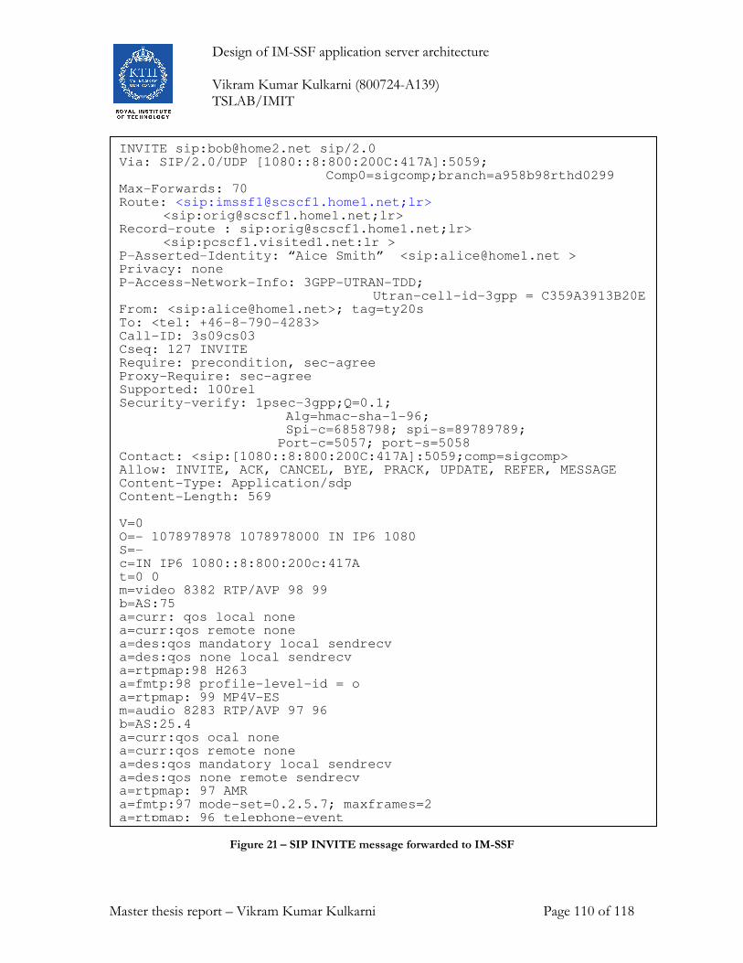
Design of IM-SSF application server architecture Vikram Kumar Kulkarni (800724-A139) TSLAB/IMIT
Master thesis report – Vikram Kumar Kulkarni Page 110 of 118
Figure 21 – SIP INVITE message forwarded to IM-SSF
INVITE sip:[email protected] sip/2.0 Via: SIP/2.0/UDP [1080::8:800:200C:417A]:5059; Comp0=sigcomp;branch=a958b98rthd0299 Max-Forwards: 70 Route: <sip:[email protected];lr>
<sip:[email protected];lr> Record-route : sip:[email protected];lr>
<sip:pcscf1.visited1.net:lr > P-Asserted-Identity: “Aice Smith” <sip:[email protected] > Privacy: none P-Access-Network-Info: 3GPP-UTRAN-TDD; Utran-cell-id-3gpp = C359A3913B20E From: <sip:[email protected]>; tag=ty20s To: <tel: +46-8-790-4283> Call-ID: 3s09cs03 Cseq: 127 INVITE Require: precondition, sec-agree Proxy-Require: sec-agree Supported: 100rel Security-verify: 1psec-3gpp;Q=0.1; Alg=hmac-sha-1-96; Spi-c=6858798; spi-s=89789789; Port-c=5057; port-s=5058 Contact: <sip:[1080::8:800:200C:417A]:5059;comp=sigcomp> Allow: INVITE, ACK, CANCEL, BYE, PRACK, UPDATE, REFER, MESSAGE Content-Type: Application/sdp Content-Length: 569 V=0 O=- 1078978978 1078978000 IN IP6 1080 S=- c=IN IP6 1080::8:800:200c:417A t=0 0 m=video 8382 RTP/AVP 98 99 b=AS:75 a=curr: qos local none a=curr:qos remote none a=des:qos mandatory local sendrecv a=des:qos none local sendrecv a=rtpmap:98 H263 a=fmtp:98 profile-level-id = o a=rtpmap: 99 MP4V-ES m=audio 8283 RTP/AVP 97 96 b=AS:25.4 a=curr:qos ocal none a=curr:qos remote none a=des:qos mandatory local sendrecv a=des:qos none remote sendrecv a=rtpmap: 97 AMR a=fmtp:97 mode-set=0.2.5.7; maxframes=2 a=rtpmap: 96 telephone-event

Design of IM-SSF application server architecture Vikram Kumar Kulkarni (800724-A139) TSLAB/IMIT
Master thesis report – Vikram Kumar Kulkarni Page 111 of 118
10.4 At IM-SSF
When IM-SSF receives the INVITE message it starts the I-OM-BCSM. I-OM-BCSM
immediately hits the “O_Null & Authorise_Origination_Attempt_Collect_Info” DP,
which is trigger detection point. At this DP the SSF shall map the parameters received in
the SIP INVITE parameters in the trigger table into CAP Initial DP. The more detailed
operations of IM-SSF are described in the §section 9.1.
10.5 At gsmSCF After receiving the Initial DP the gsmSCF shall check the credit for the subscriber, if the
subscriber have enough credit then gsmSCF shall send continue and Apply charging
messages. In this case, I assume that the subscriber having enough credit. The more
detailed operations of IM-SSF are described in the §section 9.1.
10.6 Back at IM-SSF Acting as back to back user agent B2BUA, IM-SSF initiates another call leg towards the
callee, and sends SIP INVITE request message to the callee. The SIP INVITE header at
IM-SSF is shown below.
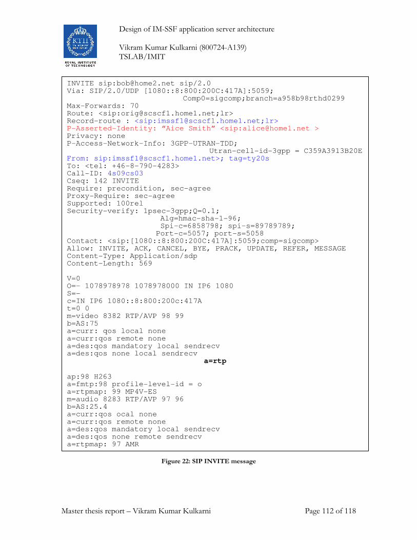
Design of IM-SSF application server architecture Vikram Kumar Kulkarni (800724-A139) TSLAB/IMIT
Master thesis report – Vikram Kumar Kulkarni Page 112 of 118
Figure 22: SIP INVITE message
INVITE sip:[email protected] sip/2.0 Via: SIP/2.0/UDP [1080::8:800:200C:417A]:5059; Comp0=sigcomp;branch=a958b98rthd0299 Max-Forwards: 70 Route: <sip:[email protected];lr> Record-route : <sip:[email protected];lr> P-Asserted-Identity: “Aice Smith” <sip:[email protected] > Privacy: none P-Access-Network-Info: 3GPP-UTRAN-TDD; Utran-cell-id-3gpp = C359A3913B20E From: sip:[email protected]>; tag=ty20s To: <tel: +46-8-790-4283> Call-ID: 4s09cs03 Cseq: 142 INVITE Require: precondition, sec-agree Proxy-Require: sec-agree Supported: 100rel Security-verify: 1psec-3gpp;Q=0.1; Alg=hmac-sha-1-96; Spi-c=6858798; spi-s=89789789; Port-c=5057; port-s=5058 Contact: <sip:[1080::8:800:200C:417A]:5059;comp=sigcomp> Allow: INVITE, ACK, CANCEL, BYE, PRACK, UPDATE, REFER, MESSAGE Content-Type: Application/sdp Content-Length: 569 V=0 O=- 1078978978 1078978000 IN IP6 1080 S=- c=IN IP6 1080::8:800:200c:417A t=0 0 m=video 8382 RTP/AVP 98 99 b=AS:75 a=curr: qos local none a=curr:qos remote none a=des:qos mandatory local sendrecv a=des:qos none local sendrecv
a=rtp
ap:98 H263 a=fmtp:98 profile-level-id = o a=rtpmap: 99 MP4V-ES m=audio 8283 RTP/AVP 97 96 b=AS:25.4 a=curr:qos ocal none a=curr:qos remote none a=des:qos mandatory local sendrecv a=des:qos none remote sendrecv a=rtpmap: 97 AMR a=fmtp:97 mode-set=0.2.5.7; maxframes=2
Design of IM-SSF application server architecture Vikram Kumar Kulkarni (800724-A139) TSLAB/IMIT
Master thesis report – Vikram Kumar Kulkarni Page 113 of 118
10.5 Back at S-CSCF Now S-CSCF tries to route the SIP INVITE message. In this case the request URI is a
TEL URL of a non IMS user. The called party sits in the PSTN.
S-CSCF makes a request to ENUM and asks for the SIP URI for the given TEL URL.
The ENUM service returns negative response as the callee is not a SIP user. S-CSCF
forwards the SIP INVITE to the BGFC (Brake out Gateway Control Function). The
BGCF routes the signaling messages based on telephone numbers.
10.6 At BGCF
BGCF selects the appropriate MGCF according to the policies of the operator. BGCF
routes the SIP INVITE message to the selected MGCF.
10.7 At Media gateway control function (MGCF)
MGCF maps the SIP messages to the ISUP messages and vice-versa. MGCF later
forwards the resulting ISUP message to the signaling gateway.
10.8 At signaling gateway
The signaling gateway forwards the ISUP Initial Address Message (ISUP IAM) out to the
PSTN. Eventually it will reach to a terminating local exchange.
10.9 At Terminating Local Exchange (TLE) Terminating local exchange prepares the ISDN SETUP message and forwards it to the
terminating party.
10.10 At callee Called party receives the ISDN SETUP message.
Now the INVITE message is reached to the callee. Callee terminal alerts the user
and sends ISDN ALERTING message back to the terminating local exchange.
10.11 Terminating party responds with ISDN ALERTING message Terminating local exchange receives the ISDN ALERTING message. TLE prepares the
ISUP Address complete message (ISUP ACM) and sends it back to the signaling gateway
at IMS home network of the calling party.
Design of IM-SSF application server architecture Vikram Kumar Kulkarni (800724-A139) TSLAB/IMIT
Master thesis report – Vikram Kumar Kulkarni Page 114 of 118
Signaling gateway forwards the ISUP ACM to the MGCF. MGCF translates the ISUP
ACM to SIP 180 ringing and sends to the IM-SSF through S-CSCF.
10.11.1 At the IM-SSF.
IM-SSF receives the SIP 180 ringing. There is no corresponding detection point of the O-
IM-BCSM in the IM-SSF. So IM-SSF acting as a SIP B2BUA sends the SIP 180 ringing
to the calling party.
10.12 Callee answers the call When callee answers the call, ISDN CONNECT message is sent to the TLE. TLE maps it
to the ISUP Answer Message (ISUP ANM). TLE sends the ISUP answer message to the
signaling MGCF at IMS home network of calling party through signaling gateway.
MGCF maps the ISUP ANM to the SIP 200 OK message and send it to the IM-SSF at
IMS home network of calling party.
10.12.1 A IM-SSF
IM-SSF receives the SIP 200 OK message. The O-IM-BCSM hits the DP O_Answer
(Refer §section 5.5.3). Now IM-SSF starts the Call period Timer (Tcp). In my model of
pre-paid operation (described in § section 9.1), at this point there will be no
communication between the gsmSCF and IM-SSF.
Acting as SIP B2BUA, the IM-SSF sends the SIP 200 OK message to the calling party.
The calling party sends the SIP ACK message to the callee, which is received by the IM-
SSF.
Now the session is established between the caller and callee. Media traffic is exchanged
between the calling and called parties.
10.13 Callee disconnects the call I assume that for the calling party has enough credit to continue the call. I also assume
that after some time the callee will disconnect the call and sends the ISDN
DISCONNECT message to the TLE.
The TLE receives the ISDN DISCONNECT message and sends ISUP release message
(ISUP REL) to the MGCF through signaling gateway.
The MGCF receives the ISUP REL and maps it to the SIP BYE message. The MGCF
sends the SIP BYE message to the IM-SSF in the home network of the caller.
IM-SSF receives the SIP BYE message. SIP BYE message corresponds to the DP
O_Disconnect in the O-IM-BCSM (Refer §section 5.5.3). As a result the IM-SSF will

Design of IM-SSF application server architecture Vikram Kumar Kulkarni (800724-A139) TSLAB/IMIT
Master thesis report – Vikram Kumar Kulkarni Page 115 of 118
sends an apply charging report (ACR) to the gsmSCF (Refer to §section 9.1). And the
IM-SSF sends SIP BYE message to the calling party.

Design of IM-SSF application server architecture Vikram Kumar Kulkarni (800724-A139) TSLAB/IMIT
Master thesis report – Vikram Kumar Kulkarni Page 116 of 118
11. Results
IMS technology is still to be mature and under active standardisation process. As of now
I now Ericson do not have this node, and I do not know any other company who had
build IM-SSF. Though companies do not have ready to use IM-SSF, some of them have a
platform from which they could build IM-SSF easily. Teligent AB, they have a
softswitch which can be used as IM-SSF with some modifications. Appium AB have an
telecom application server (X-Way) for IMS, this application server can build IM-SSF on
top of it by adding CAP interface to it.
In my work I have designed IM-SSF, to develop full fledged IM-SSF in this model could
take about 3,00,000 to 5,00,000 man hours. Which means 50 to 100 people working for 2
years.
By using three state machines for a single call, my design can model the call closest to
the real call, as close as you can get. The design is modular, and each process is designed
to take care fo well defined responsibilities. Processes are designed to handle high load
and heavy traffic. Each process can be developed as it’s own and later can be integrated
with other processes.
High level process algorithms (text) are presented in this work, are very useful for
developers to understand the functionality of each process. A complete end to end traffic
case is give to show the usage of IM-SSF in very detailed manner. A internal traffic case
of IM-SSF also given to show the processing of call inside IM-SSF. I met the design
requirements given by 3GPP i.e., do not require any change for legacy CAP interface
towards gsmSCF, as well as design goals set by my supervisor.

Design of IM-SSF application server architecture Vikram Kumar Kulkarni (800724-A139) TSLAB/IMIT
Master thesis report – Vikram Kumar Kulkarni Page 117 of 118
12. Conclusions It is always good to use the exisitng technologies and systems to the full extent rathar
than creating a new one from scratch for the same purpose. It is very good Idea to use
exisiting GsmSCF as a service control point rathar than building a another system for IN
services. GsmSCF is very complex node build over one last one decade.
Building an IM-SSF is not really a complex as it appears. Most of companies who
considering to develop IM-SSF do have a platform with SIP and CAP Interfaces. And
there are third party platforms like applium telecom platform, or teligent softswitch. One
can build IM-SSf on these platforms to reduce a lot of development time.
I think to effectively model the call is is necessary to model incoming leg, and outgoing
leg separately. I think one who considers developping IM-SSF should use 3 state
machines to model single call. This kind of structure also allows to model multiparty
calls. It is better to use interanl datatypes for processing of call inside IM-SSF. Because
IM-SSF is a complex node with sevaral interfaces, the protocol messages must be
mapped into internal messages just when it enters into the IM-SSF. So irrespective of
how many interfaces anode have, the internal processing follows it’s own data structure.
The process ImcnSSF is most complex process in IM-SSF, so special attention is needed
to develop this process. ImcnSSF itself could be 25% of whole development process. Leg
controller is heavily loaded process, which have to mantaain 3 processes () for each call,
so adding more repsonsibilities for leg contoller process is not adviced.
Design of IM-SSF application server architecture Vikram Kumar Kulkarni (800724-A139) TSLAB/IMIT
Master thesis report – Vikram Kumar Kulkarni Page 118 of 118
References 1. 3GPP 23.218 Release 5 IP Multimedia Subsystem (IMS); Stage 2
2. 3GPP 23.228 Release 5 IP Multimedia (IM) session handling; IM call model.
3. 3GPP 24.228 Release 5 Signalling flows for the IP multimedia call control based on
Session Initiation Protocol (SIP) and Session Description Protocol (SDP); Stage 3.
4. 3GPP 23.078 Release 5 Customised Applications for Mobile network Enhanced
Logic (CAMEL) Phase 4- Stage 2.
5. 3GPP 23.278 Release 5 Customised Applications for Mobile network Enhanced
Logic (CAMEL) Phase 4 - Stage 2; IM CN Interworking.
6. J. Rosenberg, H. Schulzrinne, G. Camarillo, A. Johnston, J. Peterson, R. Sparks, M.
Handley, E. Schooler, “SIP: Session Initiation Protocol”, RFC 3261, June 2002
http://www.ietf.org/rfc/rfc3261.txt
7. J. Lennox and H. Schulzrinne, and T. F. La Porta, “Implementing Intelligent Network
Service with the Session Initiation Procol, Technical Report, 1999, ISDN and SS7
architecture for digital signaling networks
8. M. Handley et al., “SIP: Session Initiation Protocol”, IETF RFC 3261, March 1999
9. M. Handley and V. Jacobson, “SDP: Session Description Protocol”, IETF RFC 2327,
April 1998
10. H. Schulzrinne et al., “RTP: a transport protocol for real-time applications”, IETF
RFC 1889, January 1996
11. 3GPP TS 23.228 IP Multimedia Subsystem (IMS); Stage 2 (Release 5)
12. The 3G IP Multimedia Subsystem: Merging the Internet and the Cellular Worlds, 2nd
Edition Gonzalo Camarillo ISBN: 0-470-01818-6
13. Intelligent networks principles and applications by john andersson. ISBN
0852969775