design of machine elements i prof. g. chakraborty department of … · 2018-02-22 · design of...
TRANSCRIPT

Design of Machine Elements IProf. G. Chakraborty
Department of Mechanical EngineeringIndian Institute of Technology – Kharagpur
Lecture - 17Design of Threaded Fasteners
Let us begin lectures on Machine Design Part 1. This is lecture number 17 and the topic is
Design of Threaded Fasteners. Now in the last lecture that is on lecture number 16 we have
learned different geometrical profiles of different kinds of threads and now threaded fasteners
as we have discussed they are very, very useful and in many machines parts, the parts are
joined together by means of threaded fasteners. So design is very, very important for this kind
of machine elements.
In this lecture, we are going to learn how to design such threaded fasteners. Now let us come
to the design. Now the design will depend on definitely on the material selected for the
fasteners.
(Refer Slide Time: 01:37)
So this are what you are seeing a list of the screw materials. Now the screw materials will be
chosen depending on the room temperature of the application Now the room temperature
applications the materials are low carbon steel this is for the light structure and maybe
medium carbon steel, but it must be heat treated. There are various process of heat treatment
and this are all specified in standards.

So when you have to design such a threaded fasteners so you will have to look into the
standard. There are different material standard and the medium carbon steel with different
kinds of heat treatments are possible. Quenching and tempering these are the 2 most useful
that is most frequently used heat treatment process. For the high temperature the alloys are
used.
Now titanium based alloys are used for high temperature then as the temperature goes high
then we use Martensitic chromium steel where the chromium is added then Inconel for a very
high temperature Inconel and super alloys are to be used. So this information is very much
essential in order to design a threaded fasteners. For any design we first need the information
about the materials because everything will be designed based on the material properties.
So these are the materials used for the screws and fasteners.
(Refer Slide Time: 03:25)
Then comes the strength of the bolts. Now strength of a machine element is not the same as
the ultimate stress of a material because this is the strength is the property of the element.
Now there are standards specifying the strength the metric standards specify the bolt strength
according to different property class of materials. There are different property classes of
materials namely ISO grades and for different property classes we have the bolt standards
specified.
The standard in any design handbook in the standard you will find there are 2 things one is
minimum yield strength and minimum ultimate strength. So when we have design any bolt

then we must see that the minimum yield strength is satisfied and minimum ultimate strength
is obtained. So these are again very important considerations for the design bolt strength as
well as the materials selected for the bolts and nuts as well and screws.
(Refer Slide Time: 04:44)
Now then we come to designing of bolt. Now the design of bolt will definitely depend on in
which application it is used. So there may be a case where the loading is normally static.
Static loading means that it does not vary with time or it varies very slowly with time it starts
from 0 and reaches on steady state value after a long time interval. So this is static loading. In
static loading there maybe cases where the pre-stress is applied and where the pre-stress is
not applied.
We are going to discuss separately these 2 where the pre-stress is applied and where is no pre-
stress. And there maybe the loading where the loading varies in cyclic manner or it will have
a fluctuating loading. Take for example one foundation which supports let us say this is the
foundation which supports one machinery which contains on rotating elements so this is as
motor for example which rotates.
Now definitely there will be some unbalance in the motor because of the manufacturing
defects and this motor is bolted to the ground. Now as it rotates so there will be a fluctuating
force develop and if you find out the free-body diagram the normal stress here on each of the
bolt will have a fluctuating component. So if you plot F against time then you will see the
variation looks somewhat like this so this is fluctuating stress.

Then there may be other situations.
(Refer Slide Time: 06:49)
Let me give you one more example the situation where so this is let us consider the
connecting rod of a Crankshaft. So this part goes to piston and bolt is applied here, a bolt is
there and this part goes to piston and now all of us know that in the piston whenever the
engine operates the force developed on the piston becomes say somewhat like this. If it is
cyclical fluctuations, but that force will always cause some fluctuating component in the
bolts.
So there are various cases where the machine parts will have fluctuating forces normally
machines are made to transmit power from one source to the other transform and transmit
power and definitely there will be some movement. So whenever there is some movement
there will be always inertial forces and definitely some other fluctuating forces. So this
fluctuating forces will be transmitted from one joint to the other through this bolts.
So bolts definitely or the joint members will be subject to the fluctuating forces all the time.
So definitely that is very important thing to consider while designing a bolt. We are going to
study some design criteria for variable loading, there may be cases where the loading is
impact. So this occurs for example in punching machine where the impact occurs definitely
the bolts connected for various parts we will also experience some impact load.
(Refer Slide Time: 09:04)

Now static loading with pre-stress. Here see that we are going to study in some more details,
but what is important that whenever we have static loading without pre-stress then the bolt
must be designed such a way that the bolt does not break under tension. So it is possible that
the bolt may break under tension. The threads are not crushed so there will be bearings stress
across the thread and that may cause the failure of the thread.
The threads may get damaged we are going to avoid to avoid that by proper designing. The
threads do not fail by shear. So this is one mode of failure where the threads my fail by shear.
The routes will have adequate strength to sustain the shear stress. These are few important
things failure modes which we have to consider.
(Refer Slide Time: 10:09)
Let us now come to one example design example. Let us consider a case where I bar is used

to lift a load. So here what I am drawing and this is the threaded member and here we have a
nut maybe we have to extend this so this is nut and a load is applied here. So this carries a
load. Definitely here there is no pre-stress and these are used for lifting certain load. Now let
us consider the screws what happens to the screw or this bolt that it is subjected to tensile
force.
Let me draw the screw in so this one ultimately this is the part connected to the nut and there
is a pressure force here. So therefore what happens is that if you consider this part it is
subjected to a tensile load and what will be the tensile stress developed. The tensile stress is
definitely sigma=P/A and the area of cross-sections. Now what is the most vulnerable
sections that is definitely here the route area there are few areas specified when you look up
at the table. So one is the route area so that is this minor diameter.
If you remember this is the area corresponding to the minor diameter. So this let me call it as
At which is the route area of the thread and so this is the maximum stress developed and this
must be < sigma allowable. We know all sigma allowable is sigma ultimate or divided by
factor of safety. Now we will have to chose At such that given a force P we have to chose At
such that this condition is satisfied and we know that At is pie/4 let us d c square where C is
the code diameter.
Now we select the code diameter and then in the table we find out what is the route area that
is code diameter and then we select the next higher size of the thread. So this is how the
thread is selected here. Now there are other modes of failure as we have mentioned in the last
slide that is the shear failure as well as the bearing failure that is the crushing failure.
(Refer Slide Time: 14:11)

Now we see that the force between this nut and the screw here nut and the bolt it depends on
various factors. So let me draw the way so let me call it this is the part of this screw and the
other part is corresponding to the nut. So this is for the nut. So definitely there will be the
clearance between the nut and the threads of the bolts. So this clearance again it will also say
what will be the total area of contact and this is the area of contact over which the bearing
pressure will act, but this is very complicated for analysis.
So we have to make very rough estimate of that because why rough because we can provide
adequate factor of safety such that the bolt does not fail even if we have a very rough estimate
that is even if the design details are not very accurate but with a large safety factor we can of
course make the design quite safe. Now what is the simplifications in design or in analysis.
The simplification is that the forces are uniformly distributed.
(Refer Slide Time: 16:12)
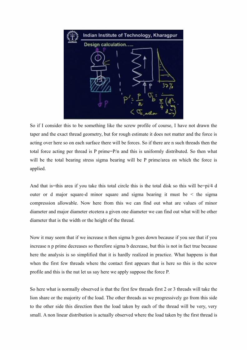
So if I consider this to be something like the screw profile of course, I have not drawn the
taper and the exact thread geometry, but for rough estimate it does not matter and the force is
acting over here so on each surface there will be forces. So if there are n such threads then the
total force acting per thread is P prime=P/n and this is uniformly distributed. So then what
will be the total bearing stress sigma bearing will be P prime/area on which the force is
applied.
And that is=this area if you take this total circle this is the total disk so this will be=pi/4 d
outer or d major square-d minor square and sigma bearing it must be < the sigma
compression allowable. Now here from this we can find out what are values of minor
diameter and major diameter etcetera a given one diameter we can find out what will be other
diameter that is the width or the height of the thread.
Now it may seem that if we increase n then sigma b goes down because if you see that if you
increase n p prime decreases so therefore sigma b decrease, but this is not in fact true because
here the analysis is so simplified that it is hardly realized in practice. What happens is that
when the first few threads where the contact first appears that is here so this is the screw
profile and this is the nut let us say here we apply suppose the force P.
So here what is normally observed is that the first few threads first 2 or 3 threads will take the
lion share or the majority of the load. The other threads as we progressively go from this side
to the other side this direction then the load taken by each of the thread will be very, very
small. A non linear distribution is actually observed where the load taken by the first thread is

almost 37%.
This is 37% and it decreases very fast and beyond 6th or 7th threads it hardly carries any
load. So here these assumptions that this load is uniformly distributed over the cross-sections
as well as over each thread is not entirely justified and we will have to make more elaborate
calculations. So here what we normally do we take n=1 but we take this load to be 37% of the
entire load.
So we calculate based on single thread which takes 37% of the load so this gives fairly good
results. Then there is another mode of failure which is the shear failure/
(Refer Slide Time: 20:29)
And if you see that the thread this is the thread where the force is acting and if you make the
same assumptions that is each of the thread will carry a force P prime and this behaves like
cantilever beam and therefore the shear stress here on this sections which is the plain for
maximum shear the shear stress will be P/so tau is P prime/area. Area is this height so pi dc
times this height h let us say. So if we have a large h then the shear stress is less.
Therefore, the (()) (21:26) thread which has the very large value of h it has a great route
strength as we have discussed in the last slide, but here the analysis also confirms that. So
here tau must be < tau allowable and tau allowable is roughly=sigma allowable/under route 3.
These are the major stresses experienced by a thread in a bolt. So there maybe there are
tensile stress as well as compressive stress again the shear stress.
(Refer Slide Time: 22:13)

So we can have when all the types of stresses are available then we can use the various
formula that is von Mises theory of failure which says that you will have to calculate this
sigma equivalent which=sigma square+ thrice tau square or you can take tau max which
is=sigma/2 under route square +tau square. Now here sigma prime must be <sigma allowable
and this must be < tau allowable.
This uses the maximum shear stress theory whereas that used the von Mises theory of failure.
So this is how the bolt is to be designed when there is not pre-stress.
(Refer Slide Time: 23:10)
Now let us see what happens when there is pre-stress. Now whenever there is a pre-stress
then we have certain advantage. We are going to see what are those advantage in some more
details, but her what is mentioned that the advantage of pre-stress is to relieve the bolts partly

from external load. So we will gradually see what are the advantages, but here now see about
the methods of pre-stressing.
When we want to pre-stress then there are few methods one very well justified method is
torque wrench method what we use a torque wrench which gives a major value of torque. The
turn-of-the-nut method is just the method where we just first tighten the nut by hand that it is
hand tighten and then we give a few turns by means of range. Now how much turn is to be
given that is calibrated, but the calibration technique is quite complicated and we are not
going to discuss here.
There are other various advanced techniques like hydraulic stretching etcetera. Normally it is
very difficult to find out what will be pre-stress value, but based on some empirical
relationship that is some experimental results we can get that these initial value, initial
tension=2840d where d is the nominal diameter of the bolt in millimeter and this is in
Newton. Normally this initial force is given.
In the next slide, we are going to see how does this pre-stressing help in relieving the bolts
from the external load.
(Refer Slide Time: 25:26)
So let us consider the case where one-cylinder cover is bolted. Here there is this is the
cylinder cover and this part is the cylinder and this is used for containing some pressurized
fluid. So therefore this must be leak proof therefore we must have a gasket here so this is
known as gasket and this is bolted. So we will use a bolt over here. Now we tighten it. The

load taken by the bolt is now will cause some initial tension here.
As you can see that whenever we tighten then if you consider the free-body diagram of this
cover plate then as we tighten it by giving some torque then what you see here the force is
here it presses and the gasket also initial force so the gasket also gives a pressure. So if you
draw the free-body diagram of the bolt then it looks like so there is F initial and F initial over
here. So this causes initial tension.
Now this tensile is again increase if we apply external load here. So now what we are going
to do we apply F external on this cover plate and see what happens. The cover plate when you
apply external force here then the bolts there are different bolts there are number of bolts
equally spaced along some circle on the cover plate. If you draw the top view of the cylinder
then what you see so if this is the cylinder then there will be number of bolts.
Here there is another bolt the number will depend on this diameter of the cover plate if you
see the standard on pressure vessels then this distance will have some minimum value so this
length P must be> some P minimum so all these considerations will give you what are the
number of bolts to be used here. Now once you use that then F external is applied on this
cover plate. So each one, each bolt will take the equal amount of external load.
Let us consider that one particular bolt takes this load F external. Although we mean that F
external is actually the load taken by the entire cover. Now based on that we can find out
what will be the new load on the bolt.
(Refer Slide Time: 30:00)

New load on the bolt what we can do is then we can find out the again we draw the free-body
diagram of the cover plate. So this is the cover plate and we have this force F fastener’s say
and F joint and this is F external. So therefore we have one equilibrium equations that is Fj+
F external- Ff is=0, but this is not sufficient to calculate Fj and Ff separately Fj is the force
experienced by this joint that is the gasket force.
We make then this is statistical indeterminate problem then we will have to use the kinematic
relationship. Now we consider the bolts to be flexible that is it has some longitudinal
flexibility along the axial directions. So if you consider that then the total extension due to the
external force.
(Refer Slide Time: 31:31)
That is Fj or Ff will be = F initial and this is again extended that is there is an extension if you
say Kf is the spring constant of the bolt then definitely the bolt acts like a spring because it
has some longitudinal flexibility and this is the delta is nothing, but the deflections of the
bolt. Similarly, the joint will be F initial- K joint times delta. So here the kinematic
relationship is that delta is same in both the cases. So the amount by which the gasket is
inflated is the amount by which the bolt is elongated.
Now if you consider this then these 3 relations will give you the value that Fj if you use that
Ff will be=F initial and delta is nothing, but if you calculate then delta will be = F external/
Kf + Kj. So if you use that then this becomes Kf/ Kf+ Kj times F external. So this is the
relation which we get. Now you can write this F initial +1 upon 1 + Kj/Kf times F external.
What we see here that this is a factor F initial + C times F external.
So here we have a factor C which is multiplied with F external. So therefore all the entire
load is not taken by the fastener, but only take a part. Now if Kj is much, much larger than Kf
that is the joint stiffness is too large then of course this terms goes very high and C becomes
very, very low. In ideal situations we can have C almost = 0. That is when there is no gasket
in between then Kj is very, very large compared to Kf and it can have a very small value C
can have a very small value.
But then one can see that by having a very small value of C one can apply a very large value
of F external that is we can if we have C 0 then we can apply infinite amount of external
force, but that is in fact not true because this statement what you are seeing here this one this
is true to some extent. If delta is too large then Fj becomes negative, but Fj cannot take any
negative load.
So therefore we can have an upper bound on delta and that means the upper bound on F
external as you can see from here. So therefore we cannot apply any arbitrary amount of load
here, but we will have to apply load in such a way that contact the gasket joint contact does
not get loosened. These are the considerations we will have to give.
(Refer Slide Time: 35:30)

Now how to calculate this Kf. Kf we can use the very known formula that is we can consider
this to be a rod if we apply force then the deformations so delta will be=F times l/EA. So
therefore Kf is almost equal to EA/L, but what about Kj. Kj calculation of Kj is very, very
complicated. When you have a gasket joint then the other parameter that is remember that
there were other elements if you consider the last example there is a cover plate then gasket
and then this one so the entire joint stiffness is based on these entire combinations.
And the gasket being very softer material compared to the other materials. So the entire
stiffness would be due to the gasket, but really whenever there is no gasket then calculations
become tremendously complicated.
(Refer Slide Time: 37:02)
What we can take that we make some simplifications and we take first term for example here

these are the 2 plates and we have a bolt here. So now when we take the joint stiffness of this
combinations then we take instead of the plate we take this first term forget about the entire
plate, but only take this amount and consider the stiffness based on this part. This also
becomes complicated and exact analysis will give very cumbersome results.
Normally in the design, we will make use of some empirical relationship that is some
experimental values of C. So what we are going to see now the C they are measured C’s are
measured experimentally. In the next slide, we are going to see the various values of C for
various kinds of joint. Now this is how the bolts are to be designed whenever there is pre-
stress.
So we have Ff=F initial+ C times F external we calculate sigma based on Ff and all other
relationships for the pre-stress will be= same as that without pre-stress.
(Refer Slide Time: 39:26)
Now we are going to see some of the values of C. Now for metal to metal joint you see then
this joint becomes very steep and the compliance that is Kj becomes very high compared to
Kf and therefore C almost becomes 0. For the narrow copper ring we have 0.01. For lead
gasket with studs we have 0.10 for soft copper gasket that is 0.40, for copper asbestos gasket
it is about 0.60 soft gasket with bolt it is 0.90 and soft gasket with stud this is 1.00.
Now these are the values used while designing the joints that is designing the bolt with pre-
stress.
(Refer Slide Time: 40:40)

Now let us calculate what are types of stresses introduced in pre-loading. What do you see is
that the tensile stress is introduced of course that is very obvious sometimes the preloading
introduces shear stress because what do you see here? there are 2 plates which are to be joint
and the bolt is there and we tighten it give a torque there. So if you consider this surface then
there will be some frictional torque acting frictional force will act.
And that will cause the frictional torque if you draw the free-body diagram of the bolt then it
looks like so this part here what we see is the frictional torque acting. So you can give
external torque the external for tightening and that will cause this Tf which is=frictional
torque. So if you calculate the shear stress due to torsions then of course you will have some
non-trivial value.
So each point will be subjected to some shear stress because of this frictional torque
developed between the 2 meetings the meeting surfaces that is the surface between the
contact point between the bolt and the surface. Then there will be other stress which is the
bending stress and that occurs whenever we have 2 misaligned or non-parallel surfaces.
(Refer Slide Time: 42:48)

Now what we are considering suppose we want to join one plate with the other. Now unlike
the previous situations here we consider that this plate is not properly aligned. So there is
some angle alpha between these 2 and we introduce we use a bolt and tighten. Definitely
while tightening the bolt will bend so there will be bending stress developed. What will be
the bending stress? let us calculate. Suppose the bending moment is M and this angle here is
the alpha.
So therefore we have this famous relationship that is EI del2w/del x square=M which while
double integrations give EI W=Mx square where we measure X from this point let us say x is
measured from this point M X square/2 + C1x+C2 and we have this boundary conditions that
is at x=0, w=0 that gives C2=0 and this is again clamed at this end. So therefore at x=0 w
prime=0 this gives C1=0 and we are left with these expressions.
So the slope at x=l slope=w prime where w is displacement from this axis so this becomes
ML/EI and this is approximately=alpha. So once alpha has some value then we can get M to
be alpha EI/L where L is the length of this bolt. Definitely what we see here that because of
this bending a bending moment is developed and this bending moment causes a bending
stress the bending stress again is given by the famous formula that is sigma bending is MY/I.
So a bending stress will be developed when we have misaligned surface. This is very
important because the bending stress maybe very, very large so that the material may fail. So
we have to ensure that these 2 meetings surfaces are parallel and if it cannot be ensured then
we sometimes use spherical washers. This semi-spherical washer is very effective for that

purpose.
So these are roughly the different kinds of stress introduced while preloading.
(Refer Slide Time: 46:50)
Now design of bolts for dynamic loading. Here the dynamic loading this is very important
and when we design the bolts for the dynamic loading then some important data are to be
considered. The first one is the stress amplitude and mean stress that is very important and
you have already learnt about it in the design of strength that is whenever we have a stress
which is fluctuating something like this and this is varying with time.
So this is sigma it has some maximum value sigma max and minimum value sigma mean.
Then the mean stress is developed as sigma max+ sigma mean/2 and amplitude stress
amplitude sigma M is sigma max-sigma mean/2. And we have fatigue failure criteria based
on this sigma mean and sigma amplitude relationship. Then the next is the fatigue stress
concentration factor.
Normally for the ductile material the stress concentration factor is not very important, but for
the brittle material it is very important for ductile material this is not so because the plastic
deformations will take place which will reduce the stress concentrations anyway, but
whenever we have fatigue loading then we have to take this fatigue stress concentration
factor. So this is again tabulated we have various kinds of bolts we have various fatigue stress
concentration is factor.
(Refer Slide Time: 49:04)

Then the corrected endurance strength the endurance strength we all know sigma E, but it is
measured for some particular type of experiments namely the bending experiments, but for
different kinds of loading we will have different factors so there are few factors one is load
factor then maybe the surface finish factor maybe the temperature factor so everything has to
be taken care and we will have to get sigma E prime which is the corrected value of this
endurance strength.
Then the yield strength or ultimate strength this is of course very much needed and the factor
of safety so this data must be supplied to the designer. Once this data is known then of course
we use various criteria.
(Refer Slide Time: 49:56)
Suppose, we know sigma max, sigma mean value and sigma amplitude then there is an

endurance diagram where sigma mean and sigma amplitude is plotted then there is one line
which is known as the Soderberg’s and that line here. So this goes up to Sy the yield strength
and this is Se. When we have a factor of safety then there is a factor of safety we get Sy
prime and Se prime. So the design must be such that it falls any design data will fall on this
line.
So therefore we have this relationship that is sigma mean/Sy prime which is=Sy/factor of
safety + S sigma amplitude/ Se/factor of safety=1 and now here we will have to introduce this
fatigue stress concentration factor over here. So this the relationship which we use there are
other relationship known as Goodman’s line or Gerber’s line, but Soderberg’s line are most
often used and this relationship will give you the value of different things like if you want the
factor of safety or the area of the bolt you can calculate with the help of this line.
We will discuss more about that in a later lecture devoted entirely to the variable loading.
(Refer Slide Time: 51:50)
So now the fatigue stress concentration factors these are the fatigue stress concentration for
metric grade this is 3.5-5.8 for the rolled thread it is 2.2 for the cut thread 2.8, 2.1 for fillet
and so on 6.6 to 10.9 this is 3.0-3.8 and 2.3.
(Refer Slide Time: 52:20)

Then we have fully corrected endurance strength this are roughly some guidelines. ISO 8.8,
M16-M36 this is 129 megapascal it increases as you go on increasing to ISO 12.9, M 1.6-
M36 that is for the metric grade 1.6-M36 it is 190 megapascal. These are all to be found out
in the handbook.
(Refer Slide Time: 52:50)
Now a small homework problem given. The homework problem looks like here the cylinder
head of a steam engine is subjected to steam pressure of 0.7 megapascal. It is held in position
by 12 bolts which will take equally the entire load, soft copper gaskets are used to remember
for the soft copper gasket was it was 0.4 to make the joint leak proof. Now in this case of
course we have the initial force and this is to be found out using this relationship 2.2840 d.
Now these are used to make the joint leak proof if the effective diameter of the cylinder is

300 millimeter find the size of bolts so that the stress does not exceed 100 megapascal. We
will have to use different data supplied to the design handbook or you can use the data from
this lecture itself. The answer to this homework problem will be given in the next lecture. So
now we come to the end of this lecture.
We have discussed how to design a bolt for the static loading as well as for the variable
loading. For the static loading we had the pre-stress and sometimes we did not have the pre-
stress advantage of pre-stress being that the bolts will be relieved of the external load to some
extent, but we cannot at all we cannot increase this external load because in that case the
contact will be loosen and the load will again increase in the bolt.
For the variable loading we have used Soderberg’s line, but there are other criteria possible.
We will use them in some more detail in a later chapter. So we come to the end. Thank you
very much.