design of movie theatre by staadd pro analysis and lsm - a
TRANSCRIPT

IOSR Journal of Mathematics (IOSR-JM)
e-ISSN: 2278-5728, p-ISSN: 2319-765X. Volume 12, Issue 6 Ver. I (Nov. - Dec.2016), PP 09-27
www.iosrjournals.org
DOI: 10.9790/5728-1206010927 www.iosrjournals.org 9 | Page
Design of Movie Theatre by STAADD Pro Analysis and LSM - A
Study
P.Yella Reddy1 and B.Rama Bhupal Reddy
2
1. Research Scholar, Department of Mathematics, Rayalaseema University, Kurnool, A.P.
2. Associate Professor, Department of Mathematics, K.S.R.M College of Engineering (Autonomous), Kadapa,
A.P.
Abstract: The design of a modern movie theatre is very complicated and it should be done very methodically
keeping in mind the innumerable number of details that it should be attended to. A certain degree of price
discrimination can be seen at movie theatres. There is a different and varied price not only for when but also for
where one sits in a movie theatre. This is to say that one is charged more for the same movie and the same
experience based on from where he or she sits. As by norm, the seats in front are charged lesser than the seats
at the back. The comfort of viewing, i.e. physical comfort is the best at the back, and worst in the front, but the
last few ‘expensive’ rows may not be the most ‘ideal’ place to watch the movie from. In this paper includes the
design of an ideal movie theatre such that one can have the best possible angle of vision using STAADD PRO
ANALYSIS and LSM
Keywords: Movie theatre, Beams, Purlins , Footing, STAADD PRO ANALYSIS , LSM.
I. Introduction
Cinema is most popular and cheapest entertainment for the people. For screening the movies to the
audience a fully fledged movie theatre is necessary. Hence, though the movie theatre is a commercial
entertainment structure, it should provide maximum facilities and comforts to the audience at a reasonable prize.
The designer will need many and varied skills – drawing, painting, construction, draftsman-ship, sewing,
budgeting, self promotion, communication, are all skills which are needed in various degrees. The designer also
needs to have an understanding of the text and of the human figure in space. So the following four principles are
Theatre design can be a lifetime study.
The audience must feel closely linked with the performers and each other
The audience should be clustered around the performers, within the limits of good sightlines
The auditorium must be scaled to sustain and enhance the performance.
The architecture should encourage a sense of excitement and community
II. Structure of a Movie Theatre
Fig 1. A simplified drawing of movie theatre
The above figure is a drawing representation of a movie theatre which depicts the following:
1. THE SCREEN
2. HEIGHT OF THE SCREEN ABOVE THE GROUND
Design of Movie Theatre by STAADD Pro Analysis and LSM-A Study
DOI: 10.9790/5728-1206010927 www.iosrjournals.org 10 | Page
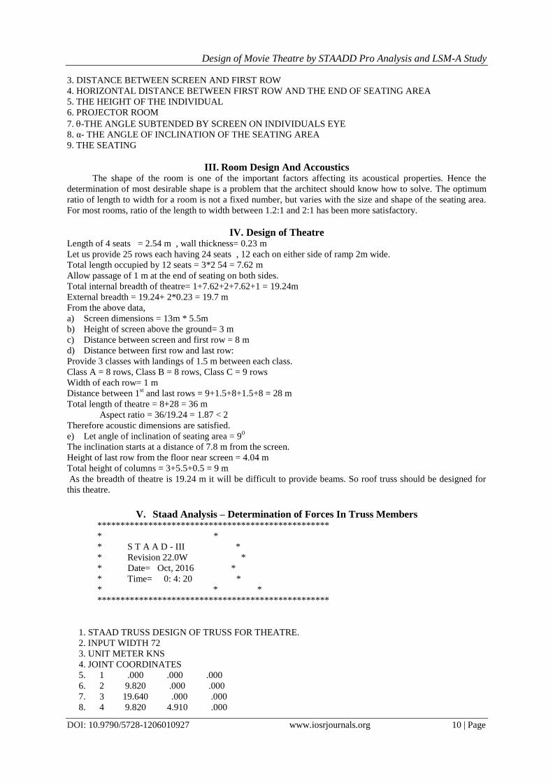
3. DISTANCE BETWEEN SCREEN AND FIRST ROW
4. HORIZONTAL DISTANCE BETWEEN FIRST ROW AND THE END OF SEATING AREA
5. THE HEIGHT OF THE INDIVIDUAL
6. PROJECTOR ROOM
7.-THE ANGLE SUBTENDED BY SCREEN ON INDIVIDUALS EYE
8. α- THE ANGLE OF INCLINATION OF THE SEATING AREA
9. THE SEATING
III. Room Design And Accoustics The shape of the room is one of the important factors affecting its acoustical properties. Hence the
determination of most desirable shape is a problem that the architect should know how to solve. The optimum
ratio of length to width for a room is not a fixed number, but varies with the size and shape of the seating area.
For most rooms, ratio of the length to width between 1.2:1 and 2:1 has been more satisfactory.
IV. Design of Theatre Length of 4 seats = 2.54 m , wall thickness= 0.23 m
Let us provide 25 rows each having 24 seats , 12 each on either side of ramp 2m wide.
Total length occupied by 12 seats = 3*2 54 = 7.62 m
Allow passage of 1 m at the end of seating on both sides.
Total internal breadth of theatre= 1+7.62+2+7.62+1 = 19.24m
External breadth = 19.24+ 2*0.23 = 19.7 m
From the above data,
a) Screen dimensions = 13m * 5.5m
b) Height of screen above the ground= 3 m
c) Distance between screen and first row = 8 m
d) Distance between first row and last row:
Provide 3 classes with landings of 1.5 m between each class.
Class A = 8 rows, Class B = 8 rows, Class C = 9 rows
Width of each row= 1 m
Distance between 1st and last rows = 9+1.5+8+1.5+8 = 28 m
Total length of theatre = 8+28 = 36 m
Aspect ratio = 36/19.24 = 1.87 < 2
Therefore acoustic dimensions are satisfied.
e) Let angle of inclination of seating area = 90
The inclination starts at a distance of 7.8 m from the screen.
Height of last row from the floor near screen = 4.04 m
Total height of columns = 3+5.5+0.5 = 9 m
As the breadth of theatre is 19.24 m it will be difficult to provide beams. So roof truss should be designed for
this theatre.
V. Staad Analysis – Determination of Forces In Truss Members **************************************************
* *
* S T A A D - III *
* Revision 22.0W *
* Date= Oct, 2016 *
* Time= 0: 4: 20 *
* * *
**************************************************
1. STAAD TRUSS DESIGN OF TRUSS FOR THEATRE.
2. INPUT WIDTH 72
3. UNIT METER KNS
4. JOINT COORDINATES
5. 1 .000 .000 .000
6. 2 9.820 .000 .000
7. 3 19.640 .000 .000
8. 4 9.820 4.910 .000
Design of Movie Theatre by STAADD Pro Analysis and LSM-A Study
DOI: 10.9790/5728-1206010927 www.iosrjournals.org 11 | Page
9. 5 2.455 .000 .000
10. 6 4.910 .000 .000
11. 7 7.365 .000 .000
12. 8 12.275 .000 .000
13. 9 14.730 .000 .000
14. 10 17.185 .000 .000
15. 11 2.455 1.227 .000
16. 12 4.910 2.455 .000
17. 13 7.365 3.683 .000
18. 14 17.185 1.227 .000
19. 15 14.730 2.455 .000
20. 16 12.275 3.683 .000
21. MEMBER INCIDENCES
22. 1 1 5
23. 2 2 8
24. 3 1 11
25. 4 2 4
26. 5 3 14
27. 6 5 6
28. 7 6 7
29. 8 7 2
30. 9 8 9
31. 10 9 10
32. 11 10 3
33. 12 11 12
34. 13 12 13
35. 14 13 4
36. 15 14 15
37. 16 15 16
38. 17 16 4
39. 18 5 11
40. 19 11 6
41. 20 6 12
42. 21 12 7
43. 22 7 13
44. 23 13 2
45. 24 2 16
46. 25 16 8
47. 26 8 15
48. 27 15 9
49. 28 9 14
50. 29 14 10
51. MEMBER PROPERTY INDIAN
52. 1 TO 3 5 TO 17 TABLE ST TUBE TH .006 WT .075 DT .075
53. 4 18 TO 29 TABLE ST TUBE TH .005 WT .05 DT .05
54. CONSTANT
55. E STEEL ALL
56. DENSITY STEEL ALL
57. POISSON STEEL ALL
58. SUPPORT
59. 1 3 FIXED
60. LOAD 1 DL
61. SELFWEIGHT Y -1.
62. MEMBER LOAD
63. 3 5 12 TO 17 UNI Y -2.
64. LOAD 2 LL
65. MEMBER LOAD
66. 3 5 12 TO 17 UNI Y -4.
67. LOAD COMB 3 DL+LL

Design of Movie Theatre by STAADD Pro Analysis and LSM-A Study
DOI: 10.9790/5728-1206010927 www.iosrjournals.org 12 | Page
68. 1 1.5 2 1.5
69. PERFORM ANALYSIS PRINT ALL
P R O B L E M S T A T I S T I C S
NUMBER OF JOINTS/MEMBER+ELEMENTS/SUPPORTS = 16/ 29/ 2
ORIGINAL/FINAL BAND-WIDTH = 14/ 3
TOTAL PRIMARY LOAD CASES = 2,
TOTAL DEGREES OF FREEDOM = 28
SIZE OF STIFFNESS MATRIX = 224 DOUBLE PREC. WORDS
REQRD/AVAIL. DISK SPACE = 12.04/ 6545.8 MB, EXMEM = 1958.9 MB
LOADING 1 DL
SELF WEIGHT Y -1.000
ACTUAL WEIGHT OF THE STRUCTURE = 8.121 KNS
MEMBER LOAD - UNIT KNS METE
MEMBER UDL L1 L2 CON L LIN1 LIN2
3 -2.000 Y .00 2.74
5 -2.000 Y .00 2.74
12 -2.000 Y .00 2.74
13 -2.000 Y .00 2.74
14 -2.000 Y .00 2.74
15 -2.000 Y .00 2.74
16 -2.000 Y .00 2.74
17 -2.000 Y .00 2.74
***TOTAL APPLIED LOAD ( KNS METE ) SUMMARY (LOADING 1 )
SUMMATION FORCE-X = .00
SUMMATION FORCE-Y = -47.40
SUMMATION FORCE-Z = .00
SUMMATION OF MOMENTS AROUND THE ORIGIN-
MX=00 , MY=00 , MZ= -465.48
LOADING 2 LL
MEMBER LOAD - UNIT KNS
MEMBER UDL L1 L2 CON L LIN1 LIN2
3 -4.000 Y .00 2.74
5 -4.000 Y .00 2.74
12 -4.000 Y .00 2.74
13 -4.000 Y .00 2.74
14 -4.000 Y .00 2.74
15 -4.000 Y .00 2.74
16 -4.000 Y .00 2.74
17 -4.000 Y .00 2.74
***TOTAL APPLIED LOAD ( KNS METE ) SUMMARY (LOADING 2 )
SUMMATION FORCE-X = .00
SUMMATION FORCE-Y = -78.56
SUMMATION FORCE-Z = .00
SUMMATION OF MOMENTS AROUND THE ORIGIN-
MX= .00 MY= .00 MZ= -771.4
++ Processing Element Stiffness Matrix. 0: 4:20
++ Processing Global Stiffness Matrix. 0: 4:20
++ Processing Triangular Factorization. 0: 4:20
++ Calculating Joint Displacements. 0: 4:20
++ Calculating Member Forces. 0: 4:20
***TOTAL REACTION ( KNS METE ) SUMMARY
LOADING 1
SUM-X= .00 SUM-Y= 47.40 SUM-Z= .00

Design of Movie Theatre by STAADD Pro Analysis and LSM-A Study
DOI: 10.9790/5728-1206010927 www.iosrjournals.org 13 | Page
SUMMATION OF MOMENTS AROUND ORIGIN-
MX= .00 MY= .00 MZ= 465.48
EXTERNAL AND INTERNAL JOINT LOAD SUMMARY-
JT EXT FX/ EXT FY/ EXT FZ/ EXT MX/ EXT MY/ EXT MZ/
INT FX INT FY INT FZ INT MX INT MY INT MZ
1 1.23 -2.79 .00 .00 .00 .00
-36.57 -20.91 .00 .00 .00 .00
2 .00 -.79 .00 .00 .00 .00
.00 .79 .00 .00 .00 .00
3 -1.23 -2.79 .00 .00 .00 .00
36.57 -20.91 .00 .00 .00 .00
4 .00 -5.43 .00 .00 .00 .00
.00 5.43 .00 .00 .00 .00
5 .00 -.35 .00 .00 .00 .00
.00 .35 .00 .00 .00 .00
6 .00 -.49 .00 .00 .00 .00
.00 .49 .00 .00 .00 .00
7 .00 -.56 .00 .00 .00 .00
.00 .56 .00 .00 .00 .00
8 .00 -.56 .00 .00 .00 .00
.00 .56 .00 .00 .00 .00
9 .00 -.49 .00 .00 .00 .00
.00 .49 .00 .00 .00 .00
10 .00 -.35 .00 .00 .00 .00
.00 .35 .00 .00 .00 .00
11 2.45 -5.40 .00 .00 .00 .00
-2.46 5.40 .00 .00 .00 .00
12 2.46 -5.46 .00 .00 .00 .00
-2.46 5.46 .00 .00 .00 .00
13 2.45 -5.54 .00 .00 .00 .00
-2.46 5.54 .00 .00 .00 .00
14 -2.45 -5.40 .00 .00 .00 .00
2.45 5.40 .00 .00 .00 .00
15 -2.46 -5.46 .00 .00 .00 .00
2.46 5.46 .00 .00 .00 .00
16 -2.45 -5.54 .00 .00 .00 .00
2.45 5.54 .00 .00 .00 .00
LOADING 2
SUM-X= .00 SUM-Y= 78.56 SUM-Z= .00
SUMMATION OF MOMENTS AROUND ORIGIN-
MX= .00 MY= .00 MZ= 771.46
EXTERNAL AND INTERNAL JOINT LOAD SUMMARY-
JT EXT FX/ EXT FY/ EXT FZ/ EXT MX/ EXT MY/ EXT MZ/
INT FX INT FY INT FZ INT MX INT MY INT MZ
1 2.45 -4.91 .00 .00 .00 .00
-59.55 -34.37 .00 .00 .00 .00
2 .00 .00 .00 .00 .00 .00
.00 .00 .00 .00 .00 .00
3 -2.45 -4.91 .00 .00 .00 .00
59.55 -34.37 .00 .00 .00 .00
4 .00 -9.82 .00 .00 .00 .00
.00 9.82 .00 .00 .00 .00
5 .00 .00 .00 .00 .00 .00
.00 .00 .00 .00 .00 .00

Design of Movie Theatre by STAADD Pro Analysis and LSM-A Study
DOI: 10.9790/5728-1206010927 www.iosrjournals.org 14 | Page
6 .00 .00 .00 .00 .00 .00
.00 .00 .00 .00 .00 .00
7 .00 .00 .00 .00 .00 .00
.00 .00 .00 .00 .00 .00
8 .00 .00 .00 .00 .00 .00
.00 .00 .00 .00 .00 .00
9 .00 .00 .00 .00 .00 .00
.00 .00 .00 .00 .00 .00
10 .00 .00 .00 .00 .00 .00
.00 .00 .00 .00 .00 .00
11 4.91 -9.82 .00 .00 .00 .00
-4.91 9.82 .00 .00 .00 .00
12 4.91 -9.82 .00 .00 .00 .00
-4.91 9.82 .00 .00 .00 .00
13 4.91 -9.82 .00 .00 .00 .00
-4.91 9.82 .00 .00 .00 .00
14 -4.91 -9.82 .00 .00 .00 .00
4.91 9.82 .00 .00 .00 .00
15 -4.91 -9.82 .00 .00 .00 .00
4.91 9.82 .00 .00 .00 .00
16 -4.91 -9.82 .00 .00 .00 .00
4.91 9.82 .00 .00 .00 .00
LOAD COMBINATION NO. 3
DL+LL
LOADING- 1. 2.
FACTOR - 1.50 1.50;-
VI. Design of Truss For Theatre JOINT DISPLACEMENT (CM RADIANS) STRUCTURE TYPE = TRUSS
JOINT LOAD X-TRANS Y-TRANS Z-TRANS
X-ROTAN Y-ROTAN Z-ROTAN
1 1 .0000 .0000 .0000 .0000 .0000 .0000
2 .0000 .0000 .0000 .0000 .0000 .0000
3 .0000 .0000 .0000 .0000 .0000 .0000
2 1 .0000 -.3421 .0000 .0000 .0000 .0000
2 .0000 -.5645 .0000 .0000 .0000 .0000
3 .0000 -1.3599 .0000 .0000 .0000 .0000
3 1 .0000 .0000 .0000 .0000 .0000 .0000
2 .0000 .0000 .0000 .0000 .0000 .0000
3 .0000 .0000 .0000 .0000 .0000 .0000
4 1 .0000 -.2824 .0000 .0000 .0000 .0000
2 .0000 -.4666 .0000 .0000 .0000 .0000
3 .0000 -1.1234 .0000 .0000 .0000 .0000
5 1 .0038 -.2224 .0000 .0000 .0000 .0000
2 .0067 -.3691 .0000 .0000 .0000 .0000
3 .0157 -.8873 .0000 .0000 .0000 .0000
6 1 .0076 -.3185 .0000 .0000 .0000 .0000
2 .0133 -.5267 .0000 .0000 .0000 .0000
3 .0315 -1.2678 .0000 .0000 .0000 .0000
7 1 .0064 -.3566 .0000 .0000 .0000 .0000
2 .0111 -.5888 .0000 .0000 .0000 .0000
3 .0263 -1.4181 .0000 .0000 .0000 .0000
8 1 -.0064 -.3566 .0000 .0000 .0000 .0000
2 -.0111 -.5888 .0000 .0000 .0000 .0000
3 -.0263 -1.4181 .0000 .0000 .0000 .0000
9 1 -.0076 -.3185 .0000 .0000 .0000 .0000
2 -.0133 -.5267 .0000 .0000 .0000 .0000
3 -.0315 -1.2678 .0000 .0000 .0000 .0000

Design of Movie Theatre by STAADD Pro Analysis and LSM-A Study
DOI: 10.9790/5728-1206010927 www.iosrjournals.org 15 | Page
10 1 -.0038 -.2224 .0000 .0000 .0000 .0000
2 -.0067 -.3691 .0000 .0000 .0000 .0000
3 -.0157 -.8873 .0000 .0000 .0000 .0000
11 1 .0688 -.2222 .0000 .0000 .0000 .0000
2 .1150 -.3691 .0000 .0000 .0000 .0000
3 .2756 -.8870 .0000 .0000 .0000 .0000
12 1 .0766 -.3132 .0000 .0000 .0000 .0000
2 .1277 -.5185 .0000 .0000 .0000 .0000
3 .3064 -1.2475 .0000 .0000 .0000 .0000
13 1 .0576 -.3412 .0000 .0000 .0000 .0000
2 .0960 -.5643 .0000 .0000 .0000 .0000
3 .2304 -1.3583 .0000 .0000 .0000 .0000
14 1 -.0688 -.2222 .0000 .0000 .0000 .0000
2 -.1150 -.3691 .0000 .0000 .0000 .0000
3 -.2756 -.8869 .0000 .0000 .0000 .0000
15 1 -.0766 -.3132 .0000 .0000 .0000 .0000
2 -.1277 -.5185 .0000 .0000 .0000 .0000
3 -.3064 -1.2475 .0000 .0000 .0000 .0000
16 1 -.0576 -.3412 .0000 .0000 .0000 .0000
2 -.0960 -.5643 .0000 .0000 .0000 .0000
3 -.2304 -1.3583 .0000 .0000 .0000 .0000
SUPPORT REACTIONS -UNIT KNS METE STRUCTURE TYPE = TRUSS
JOINT LOAD FORCE-X FORCE-Y FORCE-Z
MOM-X MOM-Y MOM Z
1 1 35.34 23.70 .00 .00 .00 .00
2 57.09 39.28 .00 .00 .00 .00
3 138.65 94.47 .00 .00 .00 .00
3 1 -35.34 23.70 .00 .00 .00 .00
2 -57.09 39.28 .00 .00 .00 .00
3 -138.65 94.47 .00 .00 .00 .00
MEMBER END FORCES STRUCTURE TYPE = TRUSS
ALL UNITS ARE -- KNS METE
MEMBER LOAD JT AXIAL SHEAR-Y SHEAR-Z
TORSION MOM-Y MOM-Z
1 1 1 -5.28 .16 .00 .00 .00 .00
5 5.28 .16 .00 .00 .00 .00
2 1 -9.22 .00 .00 .00 .00 .00
5 9.22 .00 .00 .00 .00 .00
3 1 -21.75 .23 .00 .00 .00 .00
5 21.75 .23 .00 .00 .00 .00
2 1 2 8.84 .16 .00 .00 .00 .00
8 -8.84 .16 .00 .00 .00 .00
2 2 15.36 .00 .00 .00 .00 .00
8 -15.36 .00 .00 .00 .00 .00
3 2 36.30 .23 .00 .00 .00 .00
8 -36.30 .23 .00 .00 .00 .00
3 1 1 46.86 2.90 .00 .00 .00 .00
11 -46.70 2.90 .00 .00 .00 .00
2 1 76.88 5.49 .00 .00 .00 .00
11 -76.88 5.49 .00 .00 .00 .00
3 1 185.61 12.58 .00 .00 .00 .00
11 -185.37 12.58 .00 .00 .00 .00
4 1 2 -22.27 .00 .00 .00 .00 .00
4 22.61 .00 .00 .00 .00 .00

Design of Movie Theatre by STAADD Pro Analysis and LSM-A Study
DOI: 10.9790/5728-1206010927 www.iosrjournals.org 16 | Page
2 2 -36.81 .00 .00 .00 .00 .00
4 36.81 .00 .00 .00 .00 .00
3 2 -88.62 .00 .00 .00 .00 .00
4 89.13 .00 .00 .00 .00 .00
5 1 3 46.86 2.90 .00 .00 .00 .00
14 -46.70 2.90 .00 .00 .00 .00
2 3 76.88 5.49 .00 .00 .00 .00
14 -76.88 5.49 .00 .00 .00 .00
3 3 185.61 12.58 .00 .00 .00 .00
14 -185.37 12.58 .00 .00 .00 .00
6 1 5 -5.28 .16 .00 .00 .00 .00
6 5.28 .16 .00 .00 .00 .00
2 5 -9.22 .00 .00 .00 .00 .00
6 9.22 .00 .00 .00 .00 .00
3 5 -21.75 .23 .00 .00 .00 .00
6 21.75 .23 .00 .00 .00 .00
7 1 6 1.72 .16 .00 .00 .00 .00
7 -1.72 .16 .00 .00 .00 .00
MEMBER END FORCES STRUCTURE TYPE = TRUSS
ALL UNITS ARE -- KNS METE
MEMBER LOAD JT AXIAL SHEAR-Y SHEAR-Z TORSION MOM-Y MOM-Z
2 6 3.08 .00 .00 .00 .00 .00
7 -3.08 .00 .00 .00 .00 .00
3 6 7.20 .23 .00 .00 .00 .00
7 -7.20 .23 .00 .00 .00 .00
8 1 7 8.84 .16 .00 .00 .00 .00
2 -8.84 .16 .00 .00 .00 .00
2 7 15.36 .00 .00 .00 .00 .00
2 -15.36 .00 .00 .00 .00 .00
3 7 36.30 .23 .00 .00 .00 .00
2 -36.30 .23 .00 .00 .00 .00
9 1 8 1.72 .16 .00 .00 .00 .00
9 -1.72 .16 .00 .00 .00 .00
2 8 3.08 .00 .00 .00 .00 .00
9 -3.08 .00 .00 .00 .00 .00
3 8 7.20 .23 .00 .00 .00 .00
9 -7.20 .23 .00 .00 .00 .00
10 1 9 -5.28 .16 .00 .00 .00 .00
10 5.28 .16 .00 .00 .00 .00
2 9 -9.22 .00 .00 .00 .00 .00
10 9.22 .00 .00 .00 .00 .00
3 9 -21.75 .23 .00 .00 .00 .00
10 21.75 .23 .00 .00 .00 .00
11 1 10 -5.28 .16 .00 .00 .00 .00
3 5.28 .16 .00 .00 .00 .00
2 10 -9.22 .00 .00 .00 .00 .00
3 9.22 .00 .00 .00 .00 .00
3 10 -21.75 .23 .00 .00 .00 .00
3 21.75 .23 .00 .00 .00 .00

Design of Movie Theatre by STAADD Pro Analysis and LSM-A Study
DOI: 10.9790/5728-1206010927 www.iosrjournals.org 17 | Page
12 1 11 41.79 2.90 .00 .00 .00 .00
12 -41.63 2.90 .00 .00 .00 .00
2 11 68.62 5.49 .00 .00 .00 .00
12 -68.62 5.49 .00 .00 .00 .00
3 11 165.62 12.59 .00 .00 .00 .00
12 -165.39 12.59 .00 .00 .00 .00
13 1 12 36.58 2.90 .00 .00 .00 .00
13 -36.42 2.90 .00 .00 .00 .00
2 12 60.38 5.49 .00 .00 .00 .00
13 -60.38 5.49 .00 .00 .00 .00
3 12 145.44 12.59 .00 .00 .00 .00
13 -145.20 12.59 .00 .00 .00 .00
14 1 13 31.25 2.90 .00 .00 .00 .00
4 -31.09 2.90 .00 .00 .00 .00
MEMBER END FORCES STRUCTURE TYPE = TRUSS
ALL UNITS ARE -- KNS METE
MEMBER LOAD JT AXIAL SHEAR-Y SHEAR-Z
TORSION MOM-Y MOM-Z
2 13 52.15 5.49 .00 .00 .00 .00
4 -52.15 5.49 .00 .00 .00 .00
3 13 125.09 12.58 .00 .00 .00 .00
4 -124.86 12.58 .00 .00 .00 .00
15 1 14 41.79 2.90 .00 .00 .00 .00
15 -41.63 2.90 .00 .00 .00 .00
2 14 68.62 5.49 .00 .00 .00 .00
15 -68.62 5.49 .00 .00 .00 .00
3 14 165.62 12.59 .00 .00 .00 .00
15 -165.39 12.59 .00 .00 .00 .00
16 1 15 36.58 2.90 .00 .00 .00 .00
16 -36.42 2.90 .00 .00 .00 .00
2 15 60.38 5.49 .00 .00 .00 .00
16 -60.38 5.49 .00 .00 .00 .00
3 15 145.44 12.59 .00 .00 .00 .00
16 -145.20 12.59 .00 .00 .00 .00
17 1 16 31.25 2.90 .00 .00 .00 .00
4 -31.09 2.90 .00 .00 .00 .00
2 16 52.15 5.49 .00 .00 .00 .00
4 -52.15 5.49 .00 .00 .00 .00
3 16 125.09 12.58 .00 .00 .00 .00
4 -124.86 12.58 .00 .00 .00 .00
18 1 5 -.31 .00 .00 .00 .00 .00
11 .40 .00 .00 .00 .00 .00
2 5 .00 .00 .00 .00 .00 .00
11 .00 .00 .00 .00 .00 .00
3 5 -.47 .00 .00 .00 .00 .00
11 .60 .00 .00 .00 .00 .00
19 1 11 7.78 .08 .00 .00 .00 .00
6 -7.86 .08 .00 .00 .00 .00
2 11 13.76 .00 .00 .00 .00 .00
6 -13.76 .00 .00 .00 .00 .00
3 11 32.30 .13 .00 .00 .00 .00

Design of Movie Theatre by STAADD Pro Analysis and LSM-A Study
DOI: 10.9790/5728-1206010927 www.iosrjournals.org 18 | Page
6 -32.43 .13 .00 .00 .00 .00
20 1 6 -3.90 .00 .00 .00 .00 .00
12 4.07 .00 .00 .00 .00 .00
2 6 -6.15 .00 .00 .00 .00 .00
12 6.15 .00 .00 .00 .00 .00
3 6 -15.08 .00 .00 .00 .00 .00
12 15.33 .00 .00 .00 .00 .00
21 1 12 9.98 .08 .00 .00 .00 .00
7 -10.15 .08 .00 .00 .00 .00
MEMBER END FORCES STRUCTURE TYPE = TRUSS
ALL UNITS ARE -- KNS METE
MEMBER LOAD JT AXIAL SHEAR-Y SHEAR-Z TORSION MOM-Y MOM-Z
2 12 17.37 .00 .00 .00 .00 .00
7 -17.37 .00 .00 .00 .00 .00
3 12 41.03 .13 .00 .00 .00 .00
7 -41.29 .13 .00 .00 .00 .00
22 1 7 -7.55 .00 .00 .00 .00 .00
13 7.81 .00 .00 .00 .00 .00
2 7 -12.28 .00 .00 .00 .00 .00
13 12.28 .00 .00 .00 .00 .00
3 7 -29.75 .00 .00 .00 .00 .00
13 30.13 .00 .00 .00 .00 .00
23 1 13 12.88 .08 .00 .00 .00 .00
2 -13.14 .08 .00 .00 .00 .00
2 13 22.12 .00 .00 .00 .00 .00
2 -22.12 .00 .00 .00 .00 .00
3 13 52.50 .13 .00 .00 .00 .00
2 -52.88 .13 .00 .00 .00 .00
24 1 2 13.14 .08 .00 .00 .00 .00
16 -12.88 .08 .00 .00 .00 .00
2 2 22.12 .00 .00 .00 .00 .00
16 -22.12 .00 .00 .00 .00 .00
3 2 52.88 .13 .00 .00 .00 .00
16 -52.50 .13 .00 .00 .00 .00
25 1 16 -7.81 .00 .00 .00 .00 .00
8 7.55 .00 .00 .00 .00 .00
2 16 -12.28 .00 .00 .00 .00 .00
8 12.28 .00 .00 .00 .00 .00
3 16 -30.13 .00 .00 .00 .00 .00
8 29.75 .00 .00 .00 .00 .00
26 1 8 10.15 .08 .00 .00 .00 .00
15 -9.98 .08 .00 .00 .00 .00
2 8 17.37 .00 .00 .00 .00 .00
15 -17.37 .00 .00 .00 .00 .00
3 8 41.29 .13 .00 .00 .00 .00
15 -41.03 .13 .00 .00 .00 .00
27 1 15 -4.07 .00 .00 .00 .00 .00
9 3.90 .00 .00 .00 .00 .00
2 15 -6.15 .00 .00 .00 .00 .00
9 6.15 .00 .00 .00 .00 .00

Design of Movie Theatre by STAADD Pro Analysis and LSM-A Study
DOI: 10.9790/5728-1206010927 www.iosrjournals.org 19 | Page
3 15 -15.33 .00 .00 .00 .00 .00
9 15.08 .00 .00 .00 .00 .00
28 1 9 7.86 .08 .00 .00 .00 .00
14 -7.78 .08 .00 .00 .00 .00
MEMBER END FORCES STRUCTURE TYPE = TRUSS
ALL UNITS ARE -- KNS METE
MEMBER LOAD JT AXIAL SHEAR-Y SHEAR-Z TORSION MOM-Y MOM-Z
2 9 13.76 .00 .00 .00 .00 .00
14 -13.76 .00 .00 .00 .00 .00
3 9 32.43 .13 .00 .00 .00 .00
14 -32.30 .13 .00 .00 .00 .00
29 1 14 -.40 .00 .00 .00 .00 .00
10 .31 .00 .00 .00 .00 .00
2 14 .00 .00 .00 .00 .00 .00
10 .00 .00 .00 .00 .00 .00
3 14 -.60 .00 .00 .00 .00 .00
10 .47 .00 .00 .00 .00 .00
************** END OF LATEST ANALYSIS RESULT **************
71. PLOT BENDING FILE
72. FINISH
*************** END OF STAAD-III ***************
VII. Calculations For Truss Clear span of the truss=19.24m
Assume a bearing of 20cm on either side
Effective span=19.24+0.2+0.2=19.64m
According to hand book based on IS codes,
Dead load/m2
1. Galvanian sheeting =16Kg/m2
2. Purlins (6 to 9 kg/m2) =8Kg/m
2
3. Truss weight (10 to 14kg/m2) =12 Kg/m
2
4. Weight of wind bracings =1.3Kg/m2
=37.3Kg/m2 =375N/m
2
Adopting c/c of truss=4m , Let pitch=1 in 4
Load/Panel=w*l/8 = 375*4*19.64 =367KN
8
Live Load:
As per IS-875,For roof sloping>100, LL=75Kg/m
2-(1 Kg/m
2 for 1
0 increase in slope)
>200, LL=75 Kg/m
2-(2 Kg/m
2 for 1
0 increase on slope) ,Up to minimum of 40 kg/m
2
Rise of span=19.64/4=4.91m
Slope of truss=tan-1
(4.91/9.82) =26.5650
LL=75-(6.565*2)-(10*1) =52Kg/m2=520 KN/m
2
Wind load:
Basic wind pressure at Anantapur, P=100Kg/m2
1. External wind pressure as per IS-875
Wind ward slope Leeward slope
200 -0.4P -0.5P
26.5650 -0.218P (interpolation) -0.5P
300 -0.1P -0.5P
Design of Movie Theatre by STAADD Pro Analysis and LSM-A Study
DOI: 10.9790/5728-1206010927 www.iosrjournals.org 20 | Page
2. Internal wind pressure:-Assuming normal permeability, internal wind pressure = ±0.2P
3. Total wind pressure:
WIND PRESSURE WIND WARD SIDE LEE WARD SIDE
a) External -0.218P = 218 Kg/m2 -0.5P = -50 Kg/m2
b) External + Internal(-0.2P) (-0.218-0.2)P = -41.8 Kg/m2 (-0.5-0.2)P = -70 Kg/m2
c) External + Internal(+0.2P) (-0.218+0.2)P = -1.8 Kg/m2 (-0.5+0.2)P = -30 Kg/m2
Maximum is in case (b)
Diagonal length of truss = sqrt (9.822 + 4.91
2) =10.98m
Length of each panel = 10.98/4 =2.745m
Spacing of trusses = 4 m c/c
LOAD PER PANEL:
Due to DL = 366.3 Kg
LL = 52*4*2.455 = 510.64 Kg
Wind load a) wind ward side = -42*4*2.745 = -461 Kg
b) lee ward side = -70*4*2.745 = -769 Kg
VIII. Design of Truss DESIGN OF TOP CHORD (COMPRESSION MEMBER):
Maximum load = 185.61 KN
Factored load = 1.5*185.61 = 278.415 KN
Length = 2.745 m
Let us assume effective slenderness ratio to be 100
For tubular section, for the buckling curve b, the design compressive stress corresponding to effective
slenderness ratio 100 is 118 N/mm2
Therefore Area= (278.415*103/118) =2355.9 mm
2
From IS handbook (or) from S.K Duggal, pg 786, try steel tube of 160 mm Nominal bore and heavy section of
5.4 mm thickness
A = 2760mm2,Z=109cm
2,R=5.76 cm
Effective slenderness ratio= 2.745*1000 =47.65 < 180 [SAFE]
57.6
For ƛ = 47.65;fy = 250N/mm2 and buckling curve „b‟ the design compressive stress from table 7.6.
Fcd = 186.5N/mm2
Design compressive load Pd = Ac *fcd =2700*186.5
=514.74 KN > 278.415 KN [SAFE]
Hence provide steel tube of 160 mm nominal bore and heavy section of 5.4 mm thickness
DESIGN OF WELDING:-
a)Design strength of weld in tension{ lw = пd = 500m}
Tdw = fy lw te = 250*500*((5/8)*5.4) = 506.25KN > 278.415KN [SAFE]
Ɣmw 1.25 b)Design strength of weld in compression
Vdw = (410/ )*500*((5/8)*5.4) =319.563 KN > 278.415 KN [SAFE]
1.25
DESIGN OF TRUSS MEMBERS (COMPRESSION MEMBER):
Maximum load = 52.5 KN
Factored load = 1.5*52.5 = 78.75 KN
Length = 4.5 m
Let us assume effective slenderness ratio to be 100
For tubular section, for the buckling curve b, the design compressive stress corresponding to effective
slenderness ratio 100 is 118 N/mm2
Therefore Area= (78.75*103/118) =667.4 mm
2
From IS handbook pg 786, try steel tube of 90 mm Nominal bore and light section of 3.6 mm thickness
A = 1110mm2, Z=26.2cm
2, R=3.47 cm
Effective slenderness ratio= 4.5*1000 =130 < 180 [SAFE]
34.7
For ƛ = 130; fy = 250N/mm2 and buckling curve „b‟ the design compressive stress from table 7.6.
Fcd = 88.3 N/mm2
Design compressive load Pd = Ac fcd =1110*88.3=98.013 KN > 78.75 KN [SAFE]

Design of Movie Theatre by STAADD Pro Analysis and LSM-A Study
DOI: 10.9790/5728-1206010927 www.iosrjournals.org 21 | Page
Hence provide steel tube of 90 mm nominal bore and light section of 3.6 mm thickness
DESIGN OF WELDING
a)Design strength of weld in tension { lw = пd = 283m}
Tdw = 250*283*((5/8)*3.6) = 159.043 KN > 78.75KN [SAFE]
1.25
b) Design strength of weld in compression
Vdw = (410/ )*283*((5/8)*3.6) =120.6 KN > 78.75 KN [SAFE]
1.25
DESIGN OF TRUSS MEMBERS (COMPRESSION MEMBER): Maximum load = 88.62 KN
Factored load = 1.5*88.62 = 132.3 KN
Length = 4.91 m
Area= TƔmo/ fy = (132.3*103*1.1/250) = 582.12 mm
2
From IS handbook (or) from S.K Duggal, pg 786, try steel tube of 65 mm Nominal bore and medium section of
3.6 mm thickness
Area provided = 820mm2 , Z=14.2cm
2, R=2.57 cm
IX. Check For Gross Section Yeilding A = T*Ɣm1 / fy => 820 = T*1.1/250 => T = 186.36 KN > 132.3 KN [SAFE]
CHECK FOR NET SECTION RUPTURE:
Tdn = An fu / Ɣm1 =820*410/1.25 = 268.9 KN > 132.3 KN [SAFE]
Hence provide steel tube of 65 mm nominal bore and heavy section of 3.6 mm thickness
DESIGN OF WELDING: a) Design strength of weld in tension { lw = пd = 204.2m}
Tdw = 250*204.2*((5/8)*6) = 153 KN > 132.3 KN [SAFE]
1.25
b) Design strength of butt weld in shear
Vdw = (410/ )*204.2*((5/8)*6) =145 KN > 132.3 KN [SAFE]
1.25
DETAILS OF TRUSS: NOMINAL BORE (mm)
CLASS THICKNESS (mm)
WEIGHT (kg/m)
AREA OF C/S (cm2)
Z ( cm3)
R (cm)
WELD (mm)
160 Heavy 5.4 21.200 27.10 109.0 5.76 3.375
90 Light 3.6 8.760 11.10 26.20 3.47 2.25
65 Medium 3,6 6.490 8.20 14.20 2.57 3.75
X. Design of Purlin Since the slope of roof truss is less than 30
0 , tubular section can be used as purlin.
According to hand book based on IS codes .
DEAD LOAD:
Galvanian sheeting = 16 Kg/m2
Purlins = 8 Kg/m2
24 Kg/m2
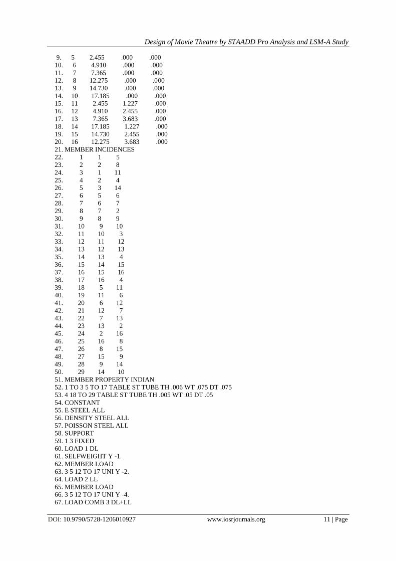
Total DL = 24*2.455*4 = 235.68 Kg = 2360 N
LIVE LOAD:
Live load as calculated earlier = 520 N/ m2
Total LL = 520*2.455*4 = 5106.4 N
WIND LOAD:
Wind load normal to roof truss = 1500 N/ m2
Total wind load = 1500*2.745*4 = 16470 N
Design of Movie Theatre by STAADD Pro Analysis and LSM-A Study
DOI: 10.9790/5728-1206010927 www.iosrjournals.org 22 | Page
Fig 2: Purlins
TOTAL LOAD = 16470+(2360+5106.4)cos26.5650 =23150 N = 23.15 KN
Maximum Bending Moment = w*l/10 =23.15*4/10 = 9.26 KNm
SECTION MODULUS:
Z = M / (1.33*0.66*fy) =9.26*106 / (1.33*0.66*415) = 25.419 cm
3
Provide medium tubular section of 90 mm nominal bore having thickness of 4mm whose sectional modulus Z=
28.8 cm3
BOLT CONNECTIONS:
Use 2- 16 mm diameter bolts,Anb = 2*0.785*п*162/4 = 315.66 mm
2
Strength of bolt in single shear = Vsb= 315.66*400 / *1.25 = 58.308 KN > 23.15 KN [SAFE]
Strength of bolt in bearing =2.5*0.5*(2*16)*4*400*10-3
/1.25 = 51.2 KN > 23.15 KN [SAFE]
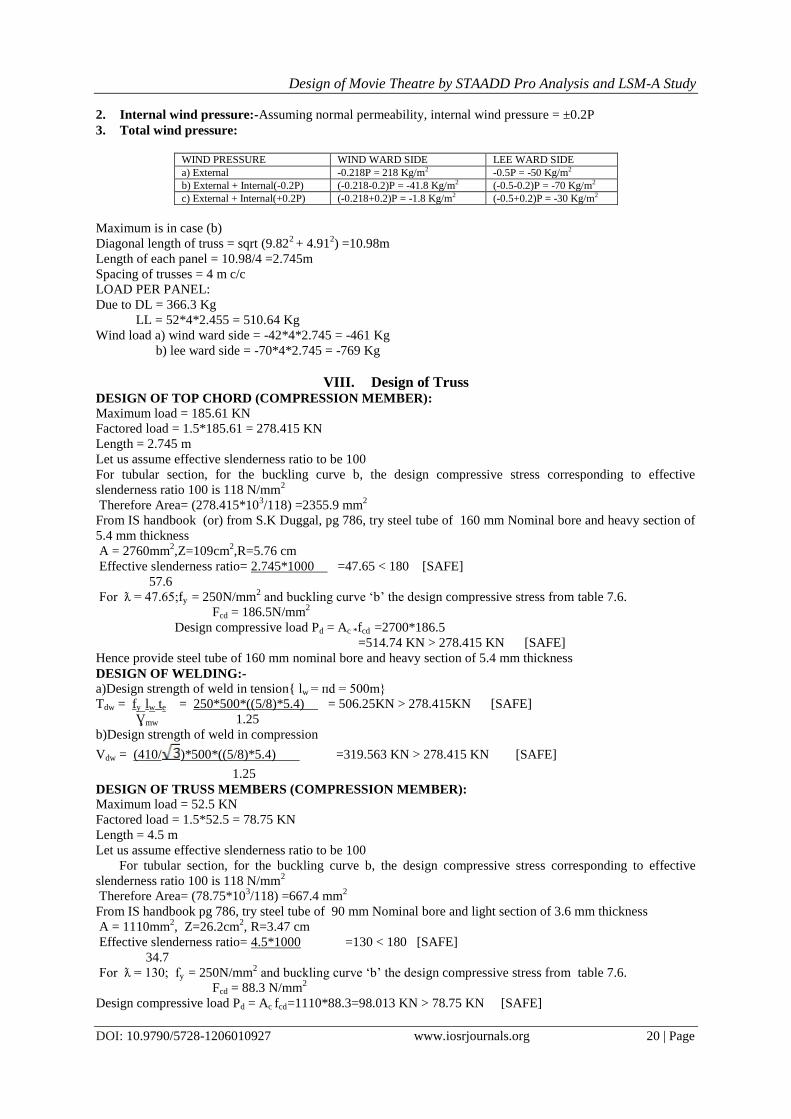
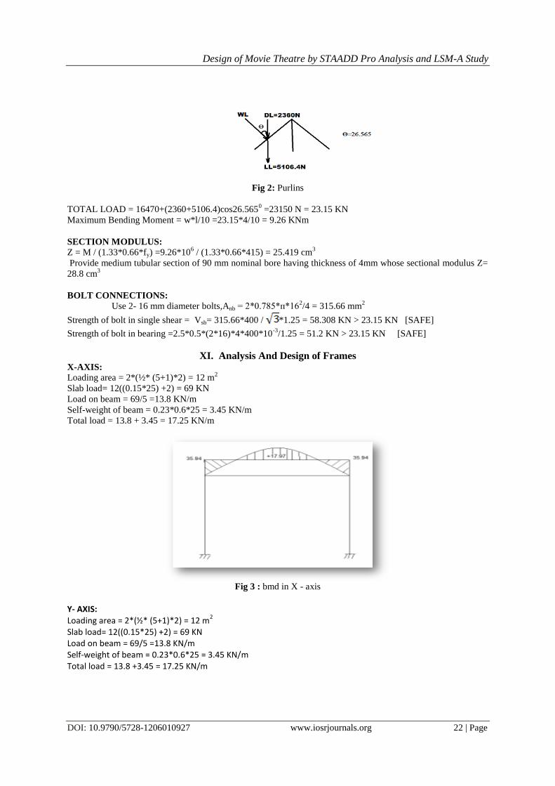
XI. Analysis And Design of Frames X-AXIS:
Loading area = 2*(½* (5+1)*2) = 12 m2
Slab load= 12((0.15*25) +2) = 69 KN
Load on beam = 69/5 =13.8 KN/m
Self-weight of beam = 0.23*0.6*25 = 3.45 KN/m
Total load = 13.8 + 3.45 = 17.25 KN/m
Fig 3 : bmd in X - axis
Y- AXIS: Loading area = 2*(½* (5+1)*2) = 12 m
2
Slab load= 12((0.15*25) +2) = 69 KN Load on beam = 69/5 =13.8 KN/m Self-weight of beam = 0.23*0.6*25 = 3.45 KN/m Total load = 13.8 +3.45 = 17.25 KN/m

Design of Movie Theatre by STAADD Pro Analysis and LSM-A Study
DOI: 10.9790/5728-1206010927 www.iosrjournals.org 23 | Page
Fig 4 : Loads
DESIGN OF SLAB
Dimensions=4m * 5m, Slab thickness = 150mm
Self-weight=0.15*1*1*25=3.75kN/m
Superimposed load=2.8kN/m2 then Total load =6.55 kN/m
2 => Wu=1.5*6.55=9.825 kN/m
2
D =150-20-8/2=126mm, lx = 4+0.126 = 4.126m, ly= 5+0.126=5.126m => ly/ lx = 1.0406
αx = 0.039 , αy=0.03 => Mux = αxwulx2 = 0.039*9.825*4.126
2 = 9.298kNm
Muy = αywulx2 = 0.03*9.825*4.126
2 = 7.152kNm
Effective depth : deff=9.298*106/0.138*20*1000 =58.04 mm < 126mm (SAFE) Under R.F.
REINFORCEMENT: For short span (middle strip):
Astx = 0.36fckbxu/0.87fy = 0.36*20*1000*0.48*126/0.87*415
Astx = 904.56 mm2,Use 8mm Φ bars = spacing = π/4 *82*1000/904.56 = 55mm
Hence provide 8 mm Φ @ 55mm c/c
For long span (middle strip):-
7.152*106 = 0.87*fy* Asty (50-415Ast/20*1000) => Asty = 500mm
2
Hence provide 8mm Φ @ 100mm c/c and 8mm Φ @ 280mm c/c in Min. area of steel
CHECK FOR SHEAR AND DEVELOPMENT LENGTHS
For shorter span :
S.F. @ longer edge = wulxr/ (2+r) = 6550*4.926*1.0406/(2+1.0406) = 11.042 KN
Nominal shear stress @ longer edges = 1.5*11042/1000*126 = 0.131N/mm2
Ast at support of short span = 1000 * π/4*82/110 = 456.9mm
2
M=0.87 * fyAst (d-0.42xu) = 0.87*415 *456.9(126-0.42*22.88) = 19.2 kNm
Lo = 230/2 -20 = 95mm => 1.3* M/V + L0> 47 Φ
1.3*19.2/11.042*1.5 +95 = 1601 > 376 mm (SAFE)
For longer span: Factored SF=1/3 wu lx =1/3*(6550*1.5)*4.926=16131
Nominal shear stress,τv=16131/1000*126=0.128N/mm2
ast= 1000*/4*82/200 = 251.5mm
2
xu = 0.87*415*251.5/0.36*20*1000 = 12.58mm
M=0.87*415*251.5(126-0.42*12.58) = 10.96kNm
1.3*10.96/16.131+95 = 978>47Φ = 376 (SAFE)
TORSIONAL REINFORCEMENT: Size of mesh=lx/5=4.126/5=0.9852 m from centre of support
= (0.23/2) + 0.9852=1.1002 m from support
Area of torsional reinforcement= (3/4) Ast x = (3/4)904.56=678.42 mm^2
Use 8 mm Ø @ spacing = (1000*π/4*82)/678.42=74 mm/cc.
Check for development length:
M.R offered by 8 mm Φ bars @ 140 mm c/c
M1= 0.87*415*(π/4)*8*2*1000/140(126-(4415*π/4882*82*1000/140)/20*1000)
M1=15.367 KNM, V =30.11 KN
Ld≤1.3M1/V +LO
=> (0.87X415Ø/4*1.2*1.6) ≤ (15.367*106/30.11*10
3)=510.36=>Ø≤14.11 mm (SAFE)
The code requires that bars must be carried into the supports by at least
Ld/3 = 510/3=170 mm.
Check for deflection:
L/D =αβγδλ , α = 26 for continuous beam , β = 1 for L < 10 m
pt = (Ast/bd)*100 = (100*π/4*82*1000/70)/1000*126 = 0.5790
Design of Movie Theatre by STAADD Pro Analysis and LSM-A Study
DOI: 10.9790/5728-1206010927 www.iosrjournals.org 24 | Page
ɤ = 1.15 for pt = 0.57 % and ϭs = 240 MR, δ=1, λ=1
L/D =29.9 , Actual L/d = 4800/126= 38.09 [SAFE]
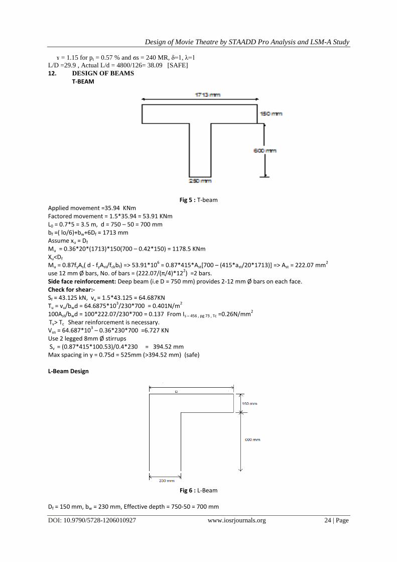
12. DESIGN OF BEAMS T-BEAM
Fig 5 : T-beam
Applied movement =35.94 KNm Factored movement = 1.5*35.94 = 53.91 KNm L0 = 0.7*5 = 3.5 m, d = 750 – 50 = 700 mm bf =( lo/6)+bw+6Df = 1713 mm Assume xu = Df Mu = 0.36*20*(1713)*150(700 – 0.42*150) = 1178.5 KNm Xu<Df Mu = 0.87fyAs( d - fyAst/fckbf) => 53.91*10
6 = 0.87*415*Ast[700 – (415*ast/20*1713)] => Ast = 222.07 mm
2
use 12 mm Ø bars, No. of bars = (222.07/(π/4)*122) =2 bars.
Side face reinforcement: Deep beam (i.e D = 750 mm) provides 2-12 mm Ø bars on each face. Check for shear:- Sf = 43.125 kN, vu = 1.5*43.125 = 64.687KN
Tu = vu/bwd = 64.6875*103/230*700 = 0.401N/m
2
100Ast/bwd = 100*222.07/230*700 = 0.137 From Is – 456 , pg 73 , Tc =0.26N/mm2
Tv> Tc Shear reinforcement is necessary. Vus = 64.687*10
3 – 0.36*230*700 =6.727 KN
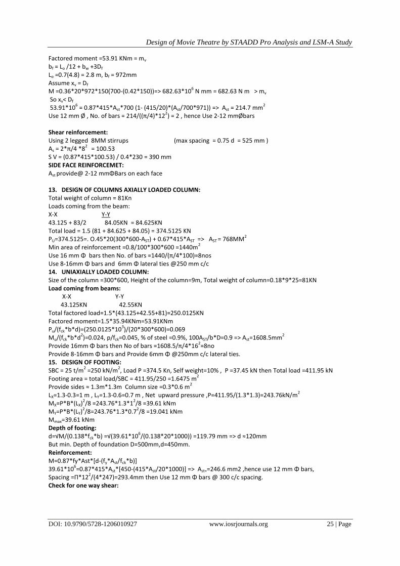
Use 2 legged 8mm Ø stirrups Sv = (0.87*415*100.53)/0.4*230 = 394.52 mm Max spacing in y = 0.75d = 525mm (>394.52 mm) (safe) L-Beam Design
Fig 6 : L-Beam
Df = 150 mm, bw = 230 mm, Effective depth = 750-50 = 700 mm
Design of Movie Theatre by STAADD Pro Analysis and LSM-A Study
DOI: 10.9790/5728-1206010927 www.iosrjournals.org 25 | Page
Factored moment =53.91 KNm = mv bf = Lo /12 + bw +3Df Lo =0.7(4.8) = 2.8 m, bf = 972mm Assume xv = Df
M =0.36*20*972*150(700-(0.42*150))=> 682.63*106 N mm = 682.63 N m > mv
So xv< Df 53.91*10
6 = 0.87*415*Ast*700 (1- (415/20)*(Ast/700*971)) => Ast = 214.7 mm
2
Use 12 mm Ø , No. of bars = 214/((π/4)*122) = 2 , hence Use 2-12 mmØbars
Shear reinforcement: Using 2 legged 8MM stirrups (max spacing = 0.75 d = 525 mm ) As = 2*π/4 *8
2 = 100.53
S V = (0.87*415*100.53) / 0.4*230 = 390 mm SIDE FACE REINFORCEMET: Ast provide@ 2-12 mmΦBars on each face 13. DESIGN OF COLUMNS AXIALLY LOADED COLUMN: Total weight of column = 81Kn Loads coming from the beam: X-X Y-Y 43.125 + 83/2 84.05KN = 84.625KN Total load = 1.5 (81 + 84.625 + 84.05) = 374.5125 KN PU=374.5125=. O.45*20(300*600-AST) + 0.67*415*AST => AST = 768MM
2
Min area of reinforcement =0.8/100*300*600 =1440m2
Use 16 mm Φ bars then No. of bars =1440/(π/4*100)=8nos Use 8-16mm Φ bars and 6mm Φ lateral ties @250 mm c/c 14. UNIAXIALLY LOADED COLUMN: Size of the column =300*600, Height of the column=9m, Total weight of column=0.18*9*25=81KN Load coming from beams: X-X Y-Y 43.125KN 42.55KN Total factored load=1.5*(43.125+42.55+81)=250.0125KN Factored moment=1.5*35.94KNm=53.91KNm Pu/(fck*b*d)=(250.0125*10
3)/(20*300*600)=0.069
Mu/(fck*b*d2)=0.024, p/fck=0.045, % of steel =0.9%, 100AST/b*D=0.9 => Ast=1608.5mm
2
Provide 16mm Φ bars then No of bars =1608.5/π/4*162=8no
Provide 8-16mm Φ bars and Provide 6mm Φ @250mm c/c lateral ties. 15. DESIGN OF FOOTING: SBC = 25 t/m
2 =250 kN/m
2, Load P =374.5 Kn, Self weight=10% , P =37.45 kN then Total load =411.95 kN
Footing area = total load/SBC = 411.95/250 =1.6475 m2
Provide sides ≈ 1.3m*1.3m Column size =0.3*0.6 m2
LX=1.3-0.3=1 m , LY=1.3-0.6=0.7 m , Net upward pressure ,P=411.95/(1.3*1.3)=243.76kN/m2
MX=P*B*(LX)2/8 =243.76*1.3*1
2/8 =39.61 kNm
MY=P*B*(LY)2/8=243.76*1.3*0.7
2/8 =19.041 kNm
Mmax=39.61 kNm Depth of footing: d=√M/(0.138*fck*b) =√(39.61*10
6/(0.138*20*1000)) =119.79 mm => d ≈120mm
But min. Depth of foundation D=500mm,d=450mm. Reinforcement: M=0.87*fy*Ast*[d-(fy*Ast/fck*b)] 39.61*10
6=0.87*415*Ast*[450-(415*Ast/20*1000)] => Ast==246.6 mm2 ,hence use 12 mm Φ bars,
Spacing =Π*122/(4*247)=293.4mm then Use 12 mm Φ bars @ 300 c/c spacing.
Check for one way shear:

Design of Movie Theatre by STAADD Pro Analysis and LSM-A Study
DOI: 10.9790/5728-1206010927 www.iosrjournals.org 26 | Page
Fig 7 : One way shear
Vu =q0(hatched area) => Vu=250*(0.05*1.3)=16.25 kN ΤV=Vu/Bd =16.25/(1.3*0.450) => 0.27 kN/m
2
100Ast/bd =0.42 ==> TC=0.41 > TV. SAFE in one way shear. Check for two way shear:
Fig 8 : One way shear
Vu=q0(hatched area) = 250(0.9025) =225.625 kN
TV=Vu/(perimeter Along dark line) => TV=225.625/(2*(0.75*1.05)) =0.625 kN/m2
TC=0.25√fck =1.118 > TV safe in two way shear
XII. Results and Discussion Actually movie theatre total height of columns is 9 m as the breadth of theatre is 19.24 m it will be
difficult to provide beams. So roof truss should be designed for this theatre using analysis of STAADD PRO and
checked all design of columns, beams, footings, portal frames using LSM.
17. CONCLUSIONS: Generally all cinema theatres should not be provided roof truss but based on the
dimensions of hall we have to provide the roof truss.
18. FUTURE WORK: This work will be done extended for Estimation of costing, valuation and quantity survey.
References [1]. NATIONAL BUILDING CODE
[2]. IS 800-1984, code of practise for general construction in steel. [3]. IS 456-2000, code of practise for plain & reinforced concrete.
[4]. “Theory of structures” by S.Ramamrutham.
[5]. “Strength of materials & Theory of structures” by B C Punmia. [6]. “SP-16” Design aids for reinforced concrete COLUMNS.
[7]. “Reinforced concrete design” by S.Unnikrishna Pillai & Menon.
[8]. “R.C.C. Designs” by B C Punmia, A K Jain & A K Jain.
Nomenclature:
A - Area
b - Effective width of the slab
bf - Effective width of the flange
bw - Breadth of web or rib
D - Overall depth of beam or slab or diameter of column
Df - Thickness of the flange

Design of Movie Theatre by STAADD Pro Analysis and LSM-A Study
DOI: 10.9790/5728-1206010927 www.iosrjournals.org 27 | Page
DL - Dead Load
d - Effective depth of beam or slab
d - Depth of compression reinforcement from the highly compressed face
EC - Modulus of elasticity of concrete
EL - Earthquake Load
ES - Modulus of elasticity of steel
e - Eccentricity
fck - Characteristic cube compressive strength of concrete
fy - Characteristic strength of steel
fα - Modulus of rupture of concrete (Flexural tensile strength)
fct - Splitting tensile strength of concrete
fd - Design strength
Hw - Unsupported height of wall
Hwe - Effective height of wall
Ief - Effective Moment of Inertia
Igr - Moment of Inertia of the gross section excluding reinforcement
Ir - Moment of Inertia of cracked section
K - Stiffness of member
k - Constant (or) Coefficient of factor
Ld - Development length
LL - Live load (or) imposed load
Lw - Horizontal distance between centres of lateral restrain
l - Length of column
lef - Effective span of beam or slab or effective length of column
lex - Effective length about x-x axis
ley - Effective length about y-y axis
ln - Clear span, face to face of supports
ln, - ln for shorter of the two spans at right angles
lx - Length of shorter side of slab
ly - Length of longer side of slab
lo - Distance between points of zero moments in a beam
ll - Span in the direction in which moments are determined, centre to centre of supports
l2 - Span transfer to l1 , centre to centre of supports
l2, - l2 for the shorter of the continuous spans
M - Bending Moment
m - Modular ratio
n - Number of samples
P - Axial load on a compression member
qau - Calculated maximum bearing pressure of soil
r - Radius
s - Spacing of stirrups (or) standard deviation
T - Torsional Moment
t - Wall thickness
V - Shear Force
W - Total load
WL - Wind load
w - Distributed load per unit area
wd - Distributed dead load per unit area
wl - Distributed live (imposed) load per unit area
x - Depth of neutral axis
Z - Modulus of section
z - Lever arm
α,β - Angle (or) ratio
ϒr - Partial safety factor for load
ϒm - Partial safety factor for material
τc - Shear stress in concrete
τc max - Maximum shear stress in concrete with shear Reinforcement
τv - Nominal shear stress
ɸ - Diameter of bar