design of multi spindle drilling machine · design of multi spindle drilling machine pravin a....
TRANSCRIPT

http://www.iaeme.com/IJDMT/index.asp 1 [email protected]
International Journal of Design and Manufacturing Technology (IJDMT)
Volume 8, Issue 2, May-August, pp. 01–22, Article ID: IJDMT_08_02_001
Available online at
http://iaeme.com/ijdmt/issues.asp?JType=IJDMT&VType=8&IType=2
Journal Impact Factor (2016): 5.7682 (Calculated by GISI) www.jifactor.com
ISSN Print: 0976 – 6995 and ISSN Online: 0976 – 7002
© IAEME Publication
DESIGN OF MULTI SPINDLE DRILLING
MACHINE
Pravin A. Desai
Lecturer, Mechanical Engg. Department,
Rajarambapu Institute of Technology, Rajramanagar, Maharashtra, India
Vishal V. Jadhav
Lecturer, Mechanical Engg. Department,
Rajarambapu Institute of Technology, Rajramanagar, Maharashtra, India
ABSTRACT
The growth of Indian manufacturing sector depends largely on its productivity &
quality. Productivity depends upon many factors, one of the major factors being
manufacturing efficiency with which the operation /activities are carried out in the
organization. Productivity can be improved by reducing the total machining time,
combining the operations etc. In case of mass production where variety of jobs is less
and quantity to be produced is huge, it is very essential to produce the job at a faster
rate. This is not possible if we carry out the production by using general purpose
machines. The best way to improve the production rate (productivity) along with
quality is by use of special purpose machine. Usefulness and performance of the
existing radial drilling machine will be increased by designing of multispindle drilling
head attachment. This paper deals with design and development of multispindle
drilling head for cycle time optimization of the component. The report presented here
gives detailed overview of making of the Special purpose machine. This report touches
to numerous aspects of engineering, which has been covered in the curriculum of UG
and PG programs of Mechanical engineering. The report is compiled with a simple
and easy to follow approach for building up of a machine. It consist of design of gear,
shaft, bearing, etc.
Key words: multispindle, Drilling Machine, Mechanical engineering.
Cite this Article: Pravin A. Desai and Vishal V. Jadhav, Design of Multi Spindle
Drilling Machine. International Journal of Design and Manufacturing Technology
8(2), 2017, pp. 01–22. http://www.iaeme.com/IJDMT/issues.asp?JType=IJDMT&VType=8&IType=2
1. INTRODUCTION
An effort is taken to design and develop a Special purpose machine for Multi spindle drilling
of cylinder head. The machine is meant for drilling 12 holes at bottom faces of the cylinder
Pravin A. Desai and Vishal V. Jadhav
http://www.iaeme.com/IJDMT/index.asp 2 [email protected]
head, and the provision is made to accommodate two jobs in single setup. The component fits
in the assembly of diesel engines manufactured by John Deere Pune.The report presented here
gives detailed overview of making of the Special purpose machine from scratch and its
installation. The report touches to numerous aspects of engineering, which has been covered
in the curriculum of UG programs of Mechanical engineering. The report is compiled with a
simple and easy to follow approach for building up of a machine. The Special purpose
machine assembly and subassemblies are elaborated using photographs and video clips
whenever required during the process. The machine consists of fifty plus components along
with its process charts. Report covers detailed design and manufacturing scheme of selected
critical components. The testing of assembly consists of numerous mechanisms, hydraulic
power pack and actuators, a programmable logic controller circuit for auto control of
machining cycle. Total cost of production is been calculated as per the available rates of labor
and materials of standard and bought out items. The report is a complete reference manual for
design and manufacturing of the machine. We have also given my suggestions to future
development of machine and some findings which may be helpful for the customer using the
set-up. Reader’s views, observations, constructive criticism and suggestions are welcome.
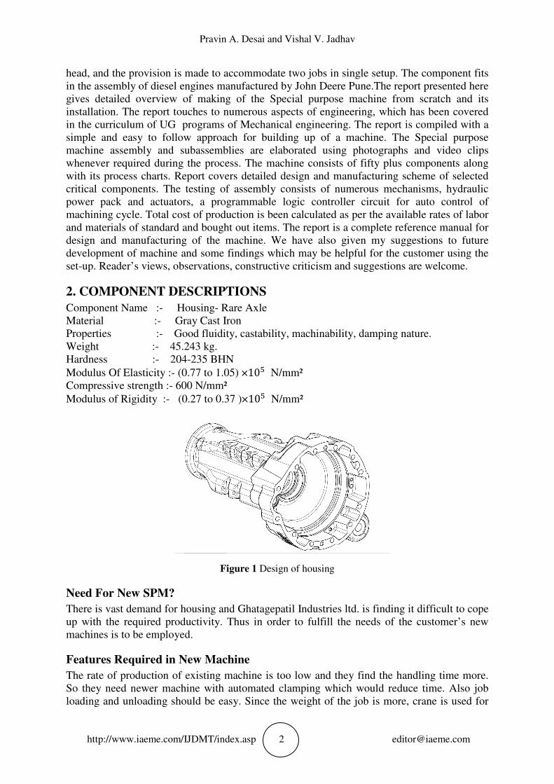
2. COMPONENT DESCRIPTIONS
Component Name :- Housing- Rare Axle
Material :- Gray Cast Iron
Properties :- Good fluidity, castability, machinability, damping nature.
Weight :- 45.243 kg.
Hardness :- 204-235 BHN
Modulus Of Elasticity :- (0.77 to 1.05) ×10� N/mm²
Compressive strength :- 600 N/mm²
Modulus of Rigidity :- (0.27 to 0.37 )×10� N/mm²
Figure 1 Design of housing
Need For New SPM?
There is vast demand for housing and Ghatagepatil Industries ltd. is finding it difficult to cope
up with the required productivity. Thus in order to fulfill the needs of the customer’s new
machines is to be employed.
Features Required in New Machine
The rate of production of existing machine is too low and they find the handling time more.
So they need newer machine with automated clamping which would reduce time. Also job
loading and unloading should be easy. Since the weight of the job is more, crane is used for
Design of Multi Spindle Drilling Machine
http://www.iaeme.com/IJDMT/index.asp 3 [email protected]
loading the job on machine. The machine should be designed taking into consideration the
loading and unloading feature of job.
3. PROPOSED METHOD
Multi Spindle Drilling
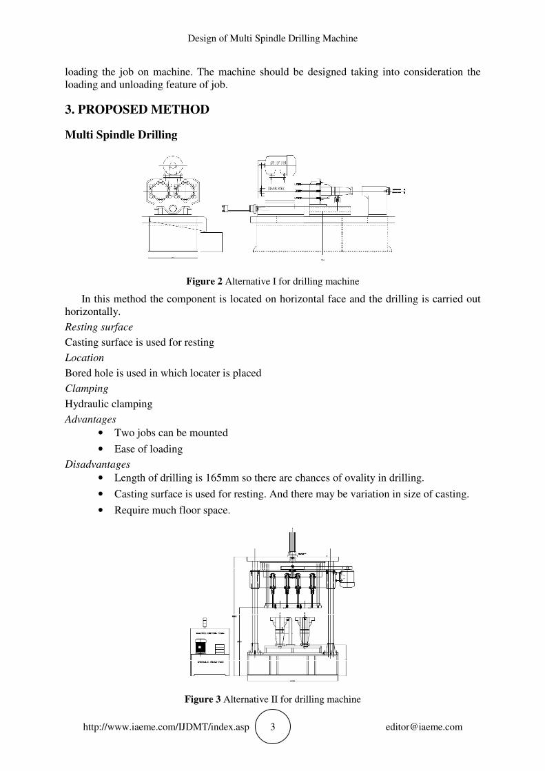
Figure 2 Alternative I for drilling machine
In this method the component is located on horizontal face and the drilling is carried out
horizontally.
Resting surface
Casting surface is used for resting
Location
Bored hole is used in which locater is placed
Clamping
Hydraulic clamping
Advantages
• Two jobs can be mounted
• Ease of loading
Disadvantages
• Length of drilling is 165mm so there are chances of ovality in drilling.
• Casting surface is used for resting. And there may be variation in size of casting.
• Require much floor space.
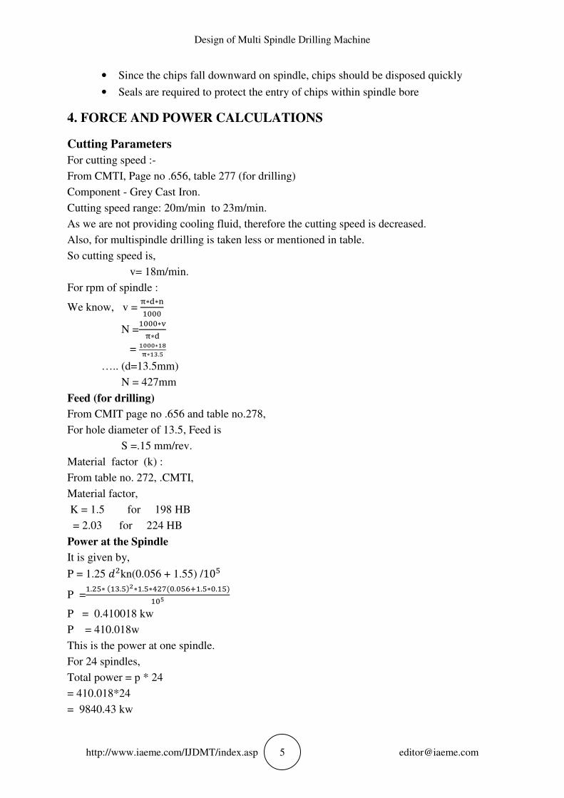
Figure 3 Alternative II for drilling machine

Pravin A. Desai and Vishal V. Jadhav
http://www.iaeme.com/IJDMT/index.asp 4 [email protected]
Job is located vertically on the machined face and the drilling is allowed to carry out in
downward direction.
Resting surface
Machined face is used for resting
Location
Bored hole is used in which locater is placed
Clamping
Hydraulic clamping
Advantages
• Two jobs can be mounted
• Since drilling is in the direction of gravity deflection of drill is minimum
• Floor space required is low
Disadvantages
• Since the job has to be loaded with the help of crane it is difficult to load the job
• Wood pecking system is required for the ease of chip disposal
Figure 4 Alternative III for drilling machine
In this method drilling is done in vertically upward direction allowing the chips to fall
downwards. Job is rested on the machined face and the dowel holes are used for locating the
jobs.
Resting surface
Machined face is used for resting
Location
Dowel holes are used in which locater is placed
Clamping
Hydraulic clamping
Advantages
• Two jobs can be mounted
• Crane can be easily operated for job loading
• Wood pecking is not required since the chips will fall downwards
• Low floor space is required
Disadvantages
• Since the drilling is done against gravity, the taper may found in drilled holes
Design of Multi Spindle Drilling Machine
http://www.iaeme.com/IJDMT/index.asp 5 [email protected]
• Since the chips fall downward on spindle, chips should be disposed quickly
• Seals are required to protect the entry of chips within spindle bore
4. FORCE AND POWER CALCULATIONS
Cutting Parameters
For cutting speed :-
From CMTI, Page no .656, table 277 (for drilling)
Component - Grey Cast Iron.
Cutting speed range: 20m/min to 23m/min.
As we are not providing cooling fluid, therefore the cutting speed is decreased.
Also, for multispindle drilling is taken less or mentioned in table.
So cutting speed is,
v= 18m/min.
For rpm of spindle :
We know, v = �∗�∗��
N =�∗
�∗�
= ����∗� �∗��.�
….. (d=13.5mm)
N = 427mm
Feed (for drilling)
From CMIT page no .656 and table no.278,
For hole diameter of 13.5, Feed is
S =.15 mm/rev.
Material factor (k) :
From table no. 272, .CMTI,
Material factor,
K = 1.5 for 198 HB
= 2.03 for 224 HB
Power at the Spindle
It is given by,
P = 1.25 ��kn(0.056 + 1.55) /10�
P =�.��∗ ���.���∗�.�∗����.����.�∗.���
��
P = 0.410018 kw
P = 410.018w
This is the power at one spindle.
For 24 spindles,
Total power = p * 24
= 410.018*24
= 9840.43 kw
Pravin A. Desai and Vishal V. Jadhav
http://www.iaeme.com/IJDMT/index.asp 6 [email protected]
Total Power = 9.840 w
�� = 9.840 kw
Efficiency of transmission is considered as 90%.
� = 90%
Power at motor is given by,
�! = ( ��) / n
= (9.840) / (0.9)
�! = 10.933 kw
This is the power of motor.
We know ,
1 HP = 746 w =0.746 kw.
Power at motor is
� = (10.933) / (0.746)
� = 14.655 HP
= 15 HP
This value is obtained from calculations.
We can use 15 HP motor. But in practice any rise in required power more than 15 HP motor is
not able to fulfill and machine may stop.
To ensure continuous running of machine ,we will use next standard motor.
We select , 20 HP
� = 20 HP
� = 14.92 kw
Torque at Spindle
Torque for 1 spindle is given by,
"# = 975 * (��/n)
= 975 * (9.84 / 427)
"#= 22.468 kgf.m
(As, 1 kgf.m = 9.81 Nm)
"# = 22.468 * 9.81 Nm
"# = 220.4148 Nm
"# = 220.4148 * 10�Nmm
This is torque at one speed.
Torque on 24 spindles is,
T = "# ∗ 24
T = 220.4148 * 10� * 24
T = 5289.956 * 10�Nmm
Thrust on Spindle
Thrust on 1 spindle is given by,
"&�=1.16kd �100 ∗ '�.(�
"&�= 1.16 * 1.5 * 13.5 * �100 ∗ 0.15�.(�
"&�= 228.454 kgf
Design of Multi Spindle Drilling Machine
http://www.iaeme.com/IJDMT/index.asp 7 [email protected]
"&�= 228.454 * 9.81 N
"&�= 2241.138 N
Now,
thrust on 24 spindles will be,
"&= "&� * 24
= 2241.138 * 24
= 53787.32 N
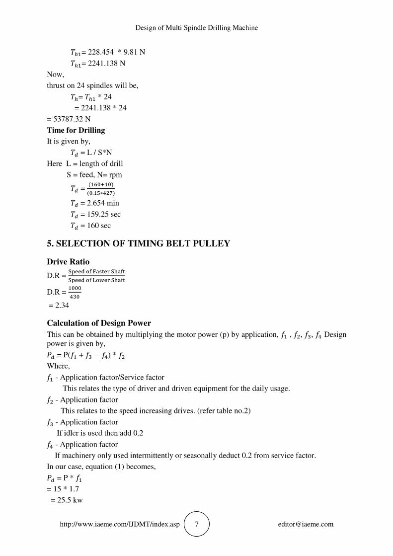
Time for Drilling
It is given by,
"* = L / S*N
Here L = length of drill
S = feed, N= rpm
"* = ������
�.��∗���� "* = 2.654 min
"* = 159.25 sec
"* = 160 sec
5. SELECTION OF TIMING BELT PULLEY
Drive Ratio
D.R = +,--� ./ 0123-4 +51/3+,--� ./ 6.7-4 +51/3
D.R = ���
= 2.34
Calculation of Design Power
This can be obtained by multiplying the motor power (p) by application, 8� , 8�, 8�, 8� Design
power is given by,
9* = P(8� + 8� − 8�) * 8�
Where,
8� - Application factor/Service factor
This relates the type of driver and driven equipment for the daily usage.
8� - Application factor
This relates to the speed increasing drives. (refer table no.2)
8� - Application factor
If idler is used then add 0.2
8� - Application factor
If machinery only used intermittently or seasonally deduct 0.2 from service factor.
In our case, equation (1) becomes,
9* = P * 8�
= 15 * 1.7
= 25.5 kw
Pravin A. Desai and Vishal V. Jadhav
http://www.iaeme.com/IJDMT/index.asp 8 [email protected]
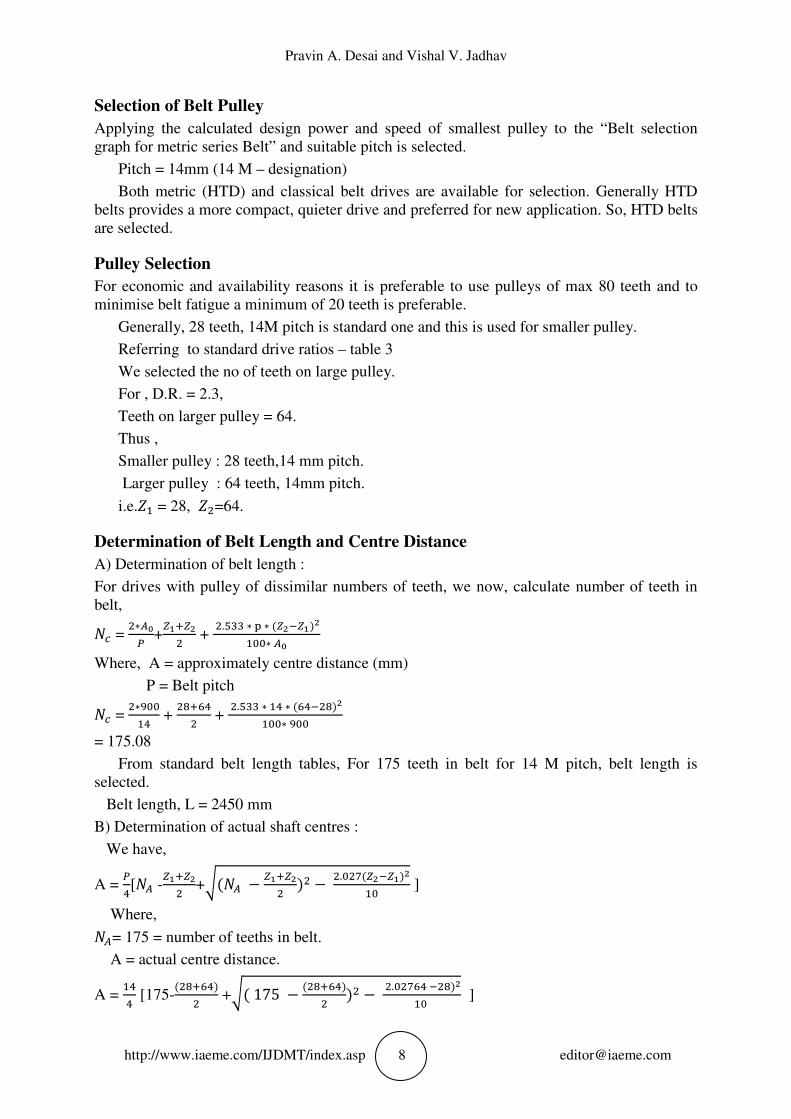
Selection of Belt Pulley
Applying the calculated design power and speed of smallest pulley to the “Belt selection
graph for metric series Belt” and suitable pitch is selected.
Pitch = 14mm (14 M – designation)
Both metric (HTD) and classical belt drives are available for selection. Generally HTD
belts provides a more compact, quieter drive and preferred for new application. So, HTD belts
are selected.
Pulley Selection
For economic and availability reasons it is preferable to use pulleys of max 80 teeth and to
minimise belt fatigue a minimum of 20 teeth is preferable.
Generally, 28 teeth, 14M pitch is standard one and this is used for smaller pulley.
Referring to standard drive ratios – table 3
We selected the no of teeth on large pulley.
For , D.R. = 2.3,
Teeth on larger pulley = 64.
Thus ,
Smaller pulley : 28 teeth,14 mm pitch.
Larger pulley : 64 teeth, 14mm pitch.
i.e.;� = 28, ;�=64.
Determination of Belt Length and Centre Distance
A) Determination of belt length :
For drives with pulley of dissimilar numbers of teeth, we now, calculate number of teeth in
belt,
<= = �∗>�
? +@��@�
� + �.��� ∗ , ∗ �@�A@���
�∗ >�
Where, A = approximately centre distance (mm)
P = Belt pitch
<= = �∗B
�� + �(���
� + �.��� ∗ �� ∗ ���A�(��
�∗ B
= 175.08
From standard belt length tables, For 175 teeth in belt for 14 M pitch, belt length is
selected.
Belt length, L = 2450 mm
B) Determination of actual shaft centres :
We have,
A = ?�[<> -
@��@�� +C�<> − @��@�
� �� − �.���@�A@���� ]
Where,
<>= 175 = number of teeths in belt.
A = actual centre distance.
A = ��� [175-
��(����� +C� 175 − ��(����
� �� − �.���� A�(��� ]
Design of Multi Spindle Drilling Machine
http://www.iaeme.com/IJDMT/index.asp 9 [email protected]
A = 899.42 mm
Now,
9# = 9**8�* 8�
9# = 25.5 *1*1
9# = 25.5 kw
Belt Width Selection
We have, selection power
Ps = 25.5 kw
Also knowing the size of small pulley and relative shaft speed,
Referring table,we get,
Pr=13.51 kw
Now, belt width factor is given by,
Wf = ?#?E = ��.�
��.�� = 1.887
Thus, belt width factor is 1.887.
Now from table, Wf = 2.32
Belt width = 85 mm
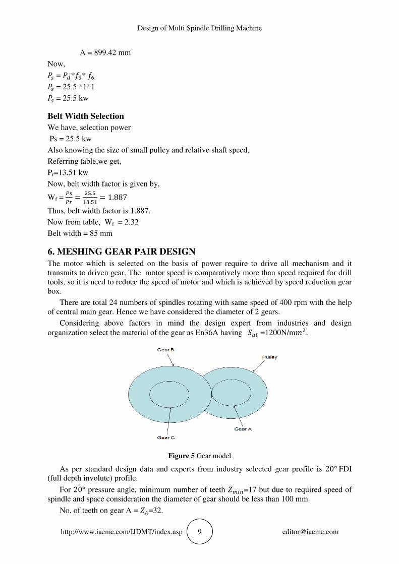
6. MESHING GEAR PAIR DESIGN
The motor which is selected on the basis of power require to drive all mechanism and it
transmits to driven gear. The motor speed is comparatively more than speed required for drill
tools, so it is need to reduce the speed of motor and which is achieved by speed reduction gear
box.
There are total 24 numbers of spindles rotating with same speed of 400 rpm with the help
of central main gear. Hence we have considered the diameter of 2 gears.
Considering above factors in mind the design expert from industries and design
organization select the material of the gear as En36A having HI� =1200N/mJ�.
Figure 5 Gear model
As per standard design data and experts from industry selected gear profile is 20° FDI
(full depth involute) profile.
For 20° pressure angle, minimum number of teeth ; L!=17 but due to required speed of
spindle and space consideration the diameter of gear should be less than 100 mm.
No. of teeth on gear A = ;>=32.
Pravin A. Desai and Vishal V. Jadhav
http://www.iaeme.com/IJDMT/index.asp 10 [email protected]
Calculation of Module
for gear pair A and B:
Power(kw) =14.92, � =1000 rpm, �> = �M=430 rpm.
The material selected for gears is En36A. It has tensile strength 'I�= 1200 N/mJ� .&
BHN = 400 case.
Now factor of safety = 1.5
Service factor = 1
Number of teeth on A are 32 i.e ;>=32, b= 12m , Y = 0.364 for ;>=32 teeth.
Pitch line velocity:
Assuming pitch line velocity as 3 m/s.
Now,velocity factor
NO=�
��� = 0.5
Module is given by,
m = {�∗ �P
Q � �RS��=#��T#�UVQ!V=W X
Y Z[\
� ]�}��
m = {�∗ �P
Q � ���.B�������.����∗��∗.�∗��∗����
� ∗ .����}��
∴ m = 3 mm.
Now,
diameter of gear = �M = `M. J
= 3*32
=96mm.
Pitch line velocity is,
v = Q*V!V
�∗� = Q∗B�∗���∗� = 2.1614 J/'
Velocity factor,
NO = 33 + e = 3
3 + 2.1614 = 0.58
Face width, b = 12m = 12*3 = 36mm.
Addendum = ℎg= module =3mm
Dedendum = ℎT=1.25m= 1.25*3=3.75mm
Clearance = c= 0.25 m = 0.25*3 =0.75 mm.
Tooth thickness = s = 1.5708 * m =1.5708*3=4.7124mm.
For gear A,
>̀ = `= = 32 , <M = 430 h�J = <>
P.C.D = m*`M =3*32=96mm.
For gear B,
`i = ��. N. ��jJ = 150
3 = 50
<k = >̀`i
× <M = 3250 = 275.2 h�J
Design of Multi Spindle Drilling Machine
http://www.iaeme.com/IJDMT/index.asp 11 [email protected]
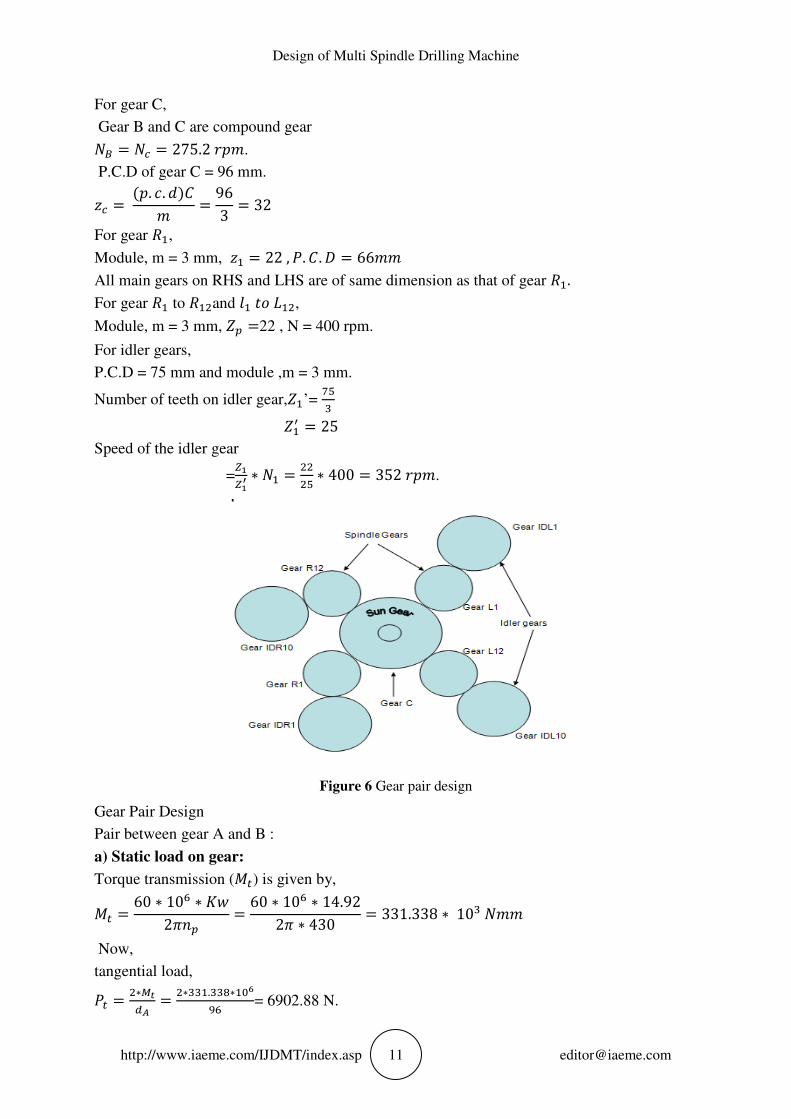
For gear C,
Gear B and C are compound gear
<k = <= = 275.2 h�J.
P.C.D of gear C = 96 mm.
`= = ��. N. ��mJ = 96
3 = 32
For gear o�,
Module, m = 3 mm, `� = 22 , 9. m. q = 66JJ All main gears on RHS and LHS are of same dimension as that of gear o�. For gear o� to o��and r� st u��,
Module, m = 3 mm, ;M =22 , N = 400 rpm.
For idler gears,
P.C.D = 75 mm and module ,m = 3 mm.
Number of teeth on idler gear,;�’= ���
;�v = 25
Speed of the idler gear
=@�@�w
∗ <� = ���� ∗ 400 = 352 h�J.
Figure 6 Gear pair design
Gear Pair Design
Pair between gear A and B :
a) Static load on gear:
Torque transmission (x�) is given by,
x� = 60 ∗ 10� ∗ yz2{�M
= 60 ∗ 10� ∗ 14.922{ ∗ 430 = 331.338 ∗ 10� <JJ
Now,
tangential load,
9� = �∗|\*} = �∗���.��(∗�P
B� = 6902.88 N.
Pravin A. Desai and Vishal V. Jadhav
http://www.iaeme.com/IJDMT/index.asp 12 [email protected]
b) Effective tooth load:
Pitch line velocity,
V =Q*}∗!}�∗� = Q∗B�∗��
�∗� = 2.1614 J/'
mO = ��O� ……. (v<10m/s)
mO = 0.5812
Effective tooth load,
9~TT=�Z∗?\
�W = �.�∗�B�.(.�(�� = 13064.6 <
Beam strength,
Hi = J ∗ � ∗ �i ∗ �
Hi = 3 ∗ 36 ∗ ��� ∗ 0.364 = 15724.8 N
"t �et�� sttsℎ 8��r�h� ��� st �������, Hi>9~TT
Hi = 9~TT ∗ 8. '
8. ' = Hi9~TT
= 15724.813064.6 = 1.2
Thus, Design is safe.
c) Dynamic load on gear
In final stage of gear design, when gear dimensions are known error specified and quality is
determined. We will select finer grade for the manufacture to reduce the dynamic load
because it is essential to get design satisfactory both from standard point of strength and wear.
The error depends upon the quantity of gear and method of manufacture.
Dynamic load is calculated by M.F.Spotts equations, it is given by,
9* = 21 e [m~i + 9�]21 e + �m~i + 9�
Hence error, e = error in tooth profile.
Gears are having the grade 6, e = 8 + 0.63 (m + 0.25√q)
For gear A, �> = 8 + 0.63 (3 + 0.25√96) = 11.43µm
For gear B, �k= 8 + 0.63 (3 + 0.25√150) = 11.82 µm
e = �> + �k = 11.43 + 11.82 = 23.25 μm
Value of deformation factor, C = 1140 N/mm�
Also, v = 2.1614 m/s, b = 36 mm and9� = 6902.88 <
Now,
9* = 21 ∗ 2.1614 ∗ �1140 ∗ 23.5 ∗ 10A� ∗ 36 + 6902.88}21 ∗ 2.1614 + ��1140 ∗ 23.25 ∗ 10A� ∗ 36� + 6902.88
9* = 4298.9 <
Now,
9~TT= G * 9�+ 9* = 1.1 * 6902.88 + 4298.9 = 11892.14 N.
8# = �X
~TT = �����.(��(B�.�� = 1.32
∴ Design is safe.
Design of Multi Spindle Drilling Machine
http://www.iaeme.com/IJDMT/index.asp 13 [email protected]
d) Wear strength is given by,
'S =�>b Q k…………………..(1)
Where, Q = ratio factor = �∗ @�
@�A@} = �∗��A�� = 5.55
K = 0.16 * �k��� ��
To avoid gear failure due to pitting, HS > 9~TT
Let, F.s = 2
HS = 2 ∗ 9~TT
HS = 2 ∗ 11892.14 = 23784.3 <
From equation (1),
23784.3 = 96 * 36 * 5.55 * 0.16 * �k��� ��
BHN = 278 ≅ 300
∴ Required hardness is 300 BHN.
Similarly this procedure is followed for all gear pairs.
7. DESIGN OF SHAFT
Design of Idler Shaft
Selection of material for shaft:
The shaft should have sufficient strength to resist failure due to breakage, provide rigidity and
gives more stability.
Considering above factors in mind the design experts from industries and design
organization select the material for shaft as SAE8620.
SAE8620 → 20 <L 2 mE 1 x�15
Composition → 0.20% C, <L- 2%, mE - 1% ,x� - 0.15%
'I� = 800 </JJ�
H]� = 530 </JJ�
Diameter of idler gear is 75mm.
Permissible shear stresses:
0.30 H]�= 0.30 * 530 = 159 </JJ�
0.18'I� = 0.18 * 800 = 144 </JJ�
Lower of these two values are selected
i.e.� = 144 �
�
Since, keyways are present.
∴ � g� = 0.75 * 144
= 108 </JJ�.
According to ASME code and maximum shear stress theory of failure.
We have,
Maximum shear stress is given by,
� g� = 16{ ∗ �� ∗ ��yi ∗ xi�� + �y� ∗ x���

Pravin A. Desai and Vishal V. Jadhav
http://www.iaeme.com/IJDMT/index.asp 14 [email protected]
Where,
yi= combined shock and fatigue factor applied to bending moment
y�= combined shock and fatigue factor applied to torsional moment
Torsional moment is given by,
x� = 9� ∗ *�
= 10793.6 ∗ 752
= 404760 N mm
For uniform load application,
yi= combined shock and fatigue factor applied to B.M = 1.5
y� = combined shock and fatigue factor applied to T.M = 1
According to ASME code and maximum shear stress theory of failure.
We have,
� g� = 16{ ∗ �� ∗ ��yi ∗ xi�� + �y� ∗ x���
�� = 16{ ∗ 10( ∗ ��1.5 ∗ 335012.8�� + �1 ∗ 404760��
�� = 24777.15
d = 29.15 mm.
The next standard diameter for shaft is
d = 30mm
Figure 7 Stress analysis for idler shaft
Design of Spindle Shaft
Selection of material for shaft:
The shaft should have sufficient strength to resist failure due to breakage, provide rigidity and
gives more stability.
Design of Multi Spindle Drilling Machine
http://www.iaeme.com/IJDMT/index.asp 15 [email protected]
Considering above factors in mind the design experts from industries and design
organization select the material for shaft as SAE8620.
SAE8620 → 20 <L 2 mE 1 x�15
Composition → 0.20% C, <L- 2%, mE - 1% ,x� - 0.15%
'I� = 800 </JJ�
H]� = 530 </JJ�
Diameter of idler gear is 75mm.
Permissible shear stresses:
0.30 H]�= 0.30 * 530 = 159 </JJ�
0.18'I� = 0.18 * 800 = 144 </JJ�
Lower of these two values are selected
i.e.� = 144 �
�
Since, keyways are present.
∴ � g� = 0.75 * 144
= 108 </JJ�.
According to ASME code and maximum shear stress theory of failure.
We have,
Maximum shear stress is given by,
� g� = 16{ ∗ �� ∗ ��yi ∗ xi�� + �y� ∗ x���
Where,
yi= combined shock and fatigue factor applied to bending moment
y�= combined shock and fatigue factor applied to torsional moment
According to ASME code and maximum shear stress theory of failure.
We have,
� g� = 16{ ∗ �� ∗ ��yi ∗ xi�� + �y� ∗ x���
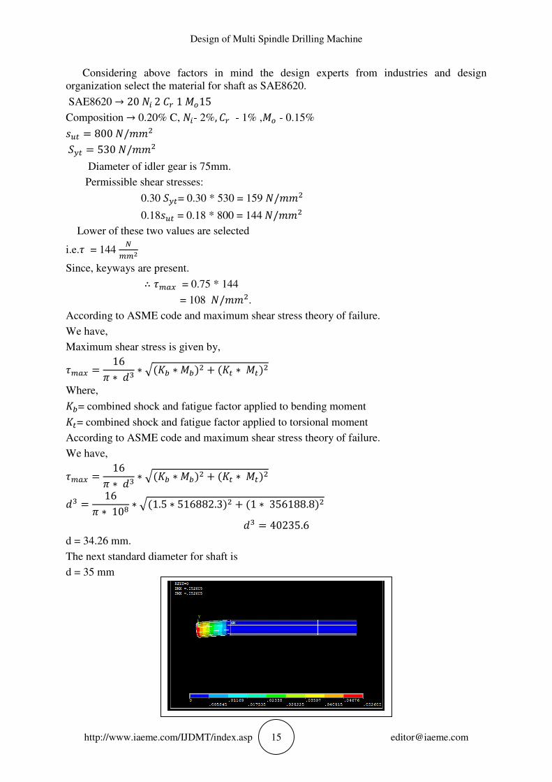
�� = 16{ ∗ 10( ∗ ��1.5 ∗ 516882.3�� + �1 ∗ 356188.8��
�� = 40235.6
d = 34.26 mm.
The next standard diameter for shaft is
d = 35 mm

Pravin A. Desai and Vishal V. Jadhav
http://www.iaeme.com/IJDMT/index.asp 16 [email protected]
Figure 8 Stress analysis for spindle shaft
Design of Intermediate Shaft
Selection of material for shaft:
The shaft should have sufficient strength to resist failure due to breakage, provide rigidity and
gives more stability.
Considering above factors in mind the design experts from industries and design
organization select the material for shaft as SAE8620.
SAE8620 → 20 <L 2 mE 1 x�15
Composition → 0.20% C, <L- 2%, mE - 1% ,x� - 0.15%
'I� = 800 </JJ�
H]� = 530 </JJ�
Diameter of gear is 150mm.
Permissible shear stresses:
0.30 H]�= 0.30 * 530 = 159 </JJ�
0.18'I� = 0.18 * 800 = 144 </JJ�
Lower of these two values are selected
i.e.� = 144 �
�
Since, keyways are present.
∴ � g� = 0.75 * 144
= 108 </JJ�.
According to ASME code and maximum shear stress theory of failure.
We have,
Maximum shear stress is given by,
� g� = 16{ ∗ �� ∗ ��yi ∗ xi�� + �y� ∗ x���
Where,
yi= combined shock and fatigue factor applied to bending moment
y�= combined shock and fatigue factor applied to torsional moment
According to ASME code and maximum shear stress theory of failure.
We have,
Design of Multi Spindle Drilling Machine
http://www.iaeme.com/IJDMT/index.asp 17 [email protected]
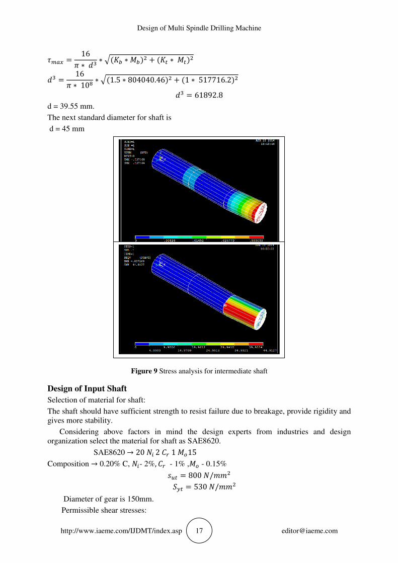
� g� = 16{ ∗ �� ∗ ��yi ∗ xi�� + �y� ∗ x���
�� = 16{ ∗ 10( ∗ ��1.5 ∗ 804040.46�� + �1 ∗ 517716.2��
�� = 61892.8
d = 39.55 mm.
The next standard diameter for shaft is
d = 45 mm
Figure 9 Stress analysis for intermediate shaft
Design of Input Shaft
Selection of material for shaft:
The shaft should have sufficient strength to resist failure due to breakage, provide rigidity and
gives more stability.
Considering above factors in mind the design experts from industries and design
organization select the material for shaft as SAE8620.
SAE8620 → 20 <L 2 mE 1 x�15
Composition → 0.20% C, <L- 2%, mE - 1% ,x� - 0.15%
'I� = 800 </JJ�
H]� = 530 </JJ�
Diameter of gear is 150mm.
Permissible shear stresses:
Pravin A. Desai and Vishal V. Jadhav
http://www.iaeme.com/IJDMT/index.asp 18 [email protected]
0.30 H]�= 0.30 * 530 = 159 </JJ�
0.18'I� = 0.18 * 800 = 144 </JJ�
Lower of these two values are selected
i.e.� = 144 �
�
Since, keyways are present.
∴ � g� = 0.75 * 144
= 108 </JJ�.
Torsional moment:-
x� = 60 ∗ 10� ∗ yz2{�
= �∗�P∗��.B�
�Q∗��
x� = 331.338 ∗ 10� <JJ
Bending moment:
9� ��� 9� are the belt tensions in tight and slack sides.
Now, (9� − 9� )*150=331.338*10�
(9� − 9� ) = 2208.9 (1)
Assume, 9� = 39�..........(2)
From equation 1 and 2
39� − 9� = 2208.9
∴ 9� = 1104.46 <
9� = 3313.38 <
Now, (9� + 9� ) = 4417.84 N
9� ��� 9Eare tangential and radial components of
9�* 48 = 331.338*10�
9� = 6902.87 N
Now, 9E = 9� ∗ tan 20
9E = 6902.87 ∗ tan 20 = 2512.4 N
According to ASME code and maximum shear stress theory of failure.
We have,
� g� = 16{ ∗ �� ∗ ��yi ∗ xi�� + �y� ∗ x���
�� = 16{ ∗ 108 ∗ ��1.5 ∗ 662676�� + �1 ∗ 331338��
�� = 49410.3
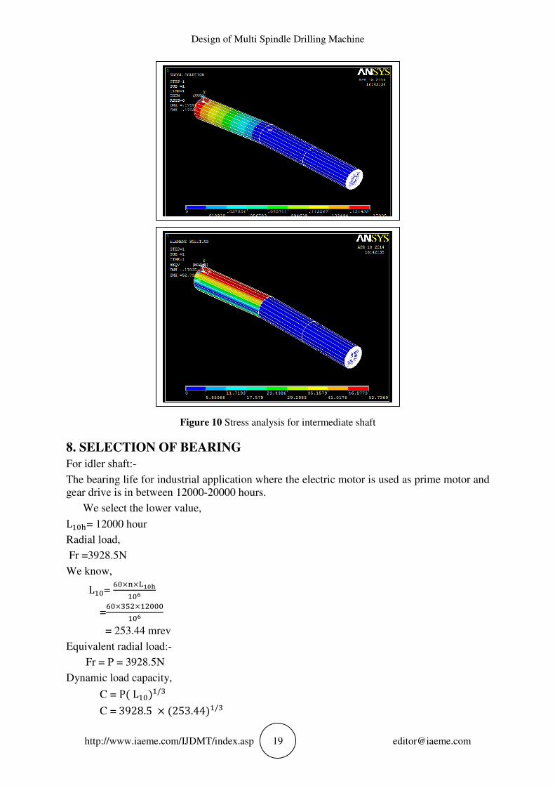
d = 36.7mm.
The next standard diameter for shaft is
d = 40 mm
Design of Multi Spindle Drilling Machine
http://www.iaeme.com/IJDMT/index.asp 19 [email protected]
Figure 10 Stress analysis for intermediate shaft
8. SELECTION OF BEARING
For idler shaft:-
The bearing life for industrial application where the electric motor is used as prime motor and
gear drive is in between 12000-20000 hours.
We select the lower value,
L�5= 12000 hour
Radial load,
Fr =3928.5N
We know,
L�= �×�×6���
�P
=������
�P
= 253.44 mrev
Equivalent radial load:-
Fr = P = 3928.5N
Dynamic load capacity,
C = P� L���/� C = 3928.5 × �253.44��/�
Pravin A. Desai and Vishal V. Jadhav
http://www.iaeme.com/IJDMT/index.asp 20 [email protected]
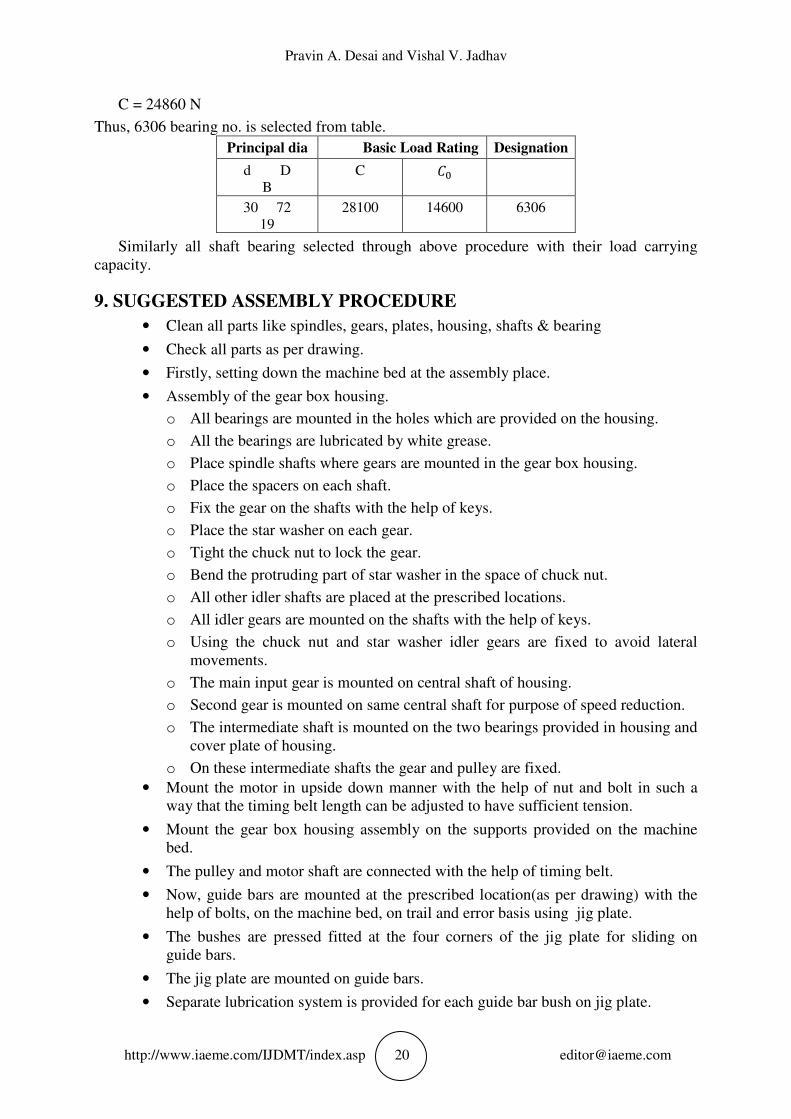
C = 24860 N
Thus, 6306 bearing no. is selected from table.
Principal dia Basic Load Rating Designation
d D
B
C m
30 72
19
28100 14600 6306
Similarly all shaft bearing selected through above procedure with their load carrying
capacity.
9. SUGGESTED ASSEMBLY PROCEDURE
• Clean all parts like spindles, gears, plates, housing, shafts & bearing
• Check all parts as per drawing.
• Firstly, setting down the machine bed at the assembly place.
• Assembly of the gear box housing.
o All bearings are mounted in the holes which are provided on the housing.
o All the bearings are lubricated by white grease.
o Place spindle shafts where gears are mounted in the gear box housing.
o Place the spacers on each shaft.
o Fix the gear on the shafts with the help of keys.
o Place the star washer on each gear.
o Tight the chuck nut to lock the gear.
o Bend the protruding part of star washer in the space of chuck nut.
o All other idler shafts are placed at the prescribed locations.
o All idler gears are mounted on the shafts with the help of keys.
o Using the chuck nut and star washer idler gears are fixed to avoid lateral
movements.
o The main input gear is mounted on central shaft of housing.
o Second gear is mounted on same central shaft for purpose of speed reduction.
o The intermediate shaft is mounted on the two bearings provided in housing and
cover plate of housing.
o On these intermediate shafts the gear and pulley are fixed.
• Mount the motor in upside down manner with the help of nut and bolt in such a
way that the timing belt length can be adjusted to have sufficient tension.
• Mount the gear box housing assembly on the supports provided on the machine
bed.
• The pulley and motor shaft are connected with the help of timing belt.
• Now, guide bars are mounted at the prescribed location(as per drawing) with the
help of bolts, on the machine bed, on trail and error basis using jig plate.
• The bushes are pressed fitted at the four corners of the jig plate for sliding on
guide bars.
• The jig plate are mounted on guide bars.
• Separate lubrication system is provided for each guide bar bush on jig plate.
Design of Multi Spindle Drilling Machine
http://www.iaeme.com/IJDMT/index.asp 21 [email protected]
• Two top covers plates are provided on guide bars.
• All the drilling holes on jig plates are provided with bushes.
• Resting pads are provided on jig plate for resting the job.
• The damping cylinders are fitted on jig plate for each job.
• For movement of jig plate the hydraulic system consisting of two hydraulic
cylinders are provided.
10. LIMITATIONS
• This Special Purpose Machine will be used only for one type of component.
• The initial investment is high.
• The cost of this machine affordable only when the production is in large quantity.
• Noise generation during drilling process.
High electricity required
11. CONCLUSIONS
The company used to manufacture around 14 jobs per shift using conventional drilling
machine. But now with advent machine operation is carried out in the cycle time of 3 min to
manufacture two pieces. By using advanced SPM, the company manufactures around 140
pieces per shift. This clearly reveals that the production rate will increase immensely. One
operator, who looks the loading and unloading of the component, can simultaneously work on
another machine .In this way, the lobour utilization of the company may improve and also add
up to improve the economy involved in the total machining. This will justify the purpose of
manufacturing this SPM machine.
12. FUTURE SCOPE
This machine can be improved in future by using different housing structures which can be
accommodated on the machine bed making set up changes as per requirements of components
with certain adjustments. Presently the SPM can drill the rear brake drum of heavy
commercial vehicle and with different models for TELCO. This machine can also be used for
their other model vehicles. Other models which differ by the centre distance between flanges
can be accommodated provided the PCD remains same. In future to cover all components the
part family flexibility can be achieved by replacing the drilling heads for components with
different PCD. So by this arrangement SPM can be used for variety of components of same
kind.
REFERENCES
[1] Machine tool design handbook, Central machine tool institute, Bangalore, 1st edition,
reprint 2006
[2] R.S.Majumdar, Oil Hydraulic systems , Tata Mcgraw Hill Publication, Edition: - 2002
[3] K. Mahadevan and K. Balaveera Reddy, Design data hand book, - CBS publishers and
distributers, third edition 1987.
[4] V.B.Bhandari ,Design of machine elements, Tata McGraw hill, 2007 Edition
[5] Dr. U. Sathish Rao and Dr. Lewlyn L.R. Rodrigues. Enhancing the Machining
Performance of HSS Drill in the Drilling of GFRP Composite by Reducing Tool Wear
through Wear Mechanism. International Journal of Mechanical Engineering and
Technology, 8(1), 2017, pp. 120–131.

Pravin A. Desai and Vishal V. Jadhav
http://www.iaeme.com/IJDMT/index.asp 22 [email protected]
[6] Syed Mohibuddin Bukhari and M. Manzoor Hussain, Greener, Evaluation of Optimum
Process Parameters in Drilling Process of Hybrid Composites using Taguchi Method.
International Journal of Mechanical Engineering and Technology, 8(4), 2017, pp. 194–
201.
[7] Vikas Mukhraiya, Raj Kumar Yadav and Pooja Tiwari, Optimization of Drilling
Parameters Using Grey Based Taguchi Method. International Journal of Advanced
Research in Engineering and Technology, 6(12), 2015, pp. 16-24