design of offshore concrete structuresbayanbox.ir/view/8175393964076000182/design-of...contents in...
TRANSCRIPT

Design of Offshore Concrete Structures
© 2000 Edited by Ivar Holand, Ove T. Gudmestad and Erik Jersin

Design of Offshore Concrete Structures
Edited by Ivar Holand, Ove T.Gudmestadand Erik Jersin
London and New York
© 2000 Edited by Ivar Holand, Ove T. Gudmestad and Erik Jersin

First published 2000 by Spon Press11 New Fetter Lane, London EC4P 4EE
Simultaneously published in the USA and Canadaby Spon Press29 West 35th Street, New York, NY 10001
Spon Press is an imprint of the Taylor & Francis Group
This edition published in the Taylor & Francis e-Library, 2003.
© 2000 Edited by Ivar Holand, Ove T.Gudmestad and Erik Jersin
All rights reserved. No part of this book may be reprinted or reproduced or utilised in any form or byany electronic, mechanical, or other means, now known or hereafter invented, including photocopyingand recording, or in any information storage or retrieval system, without permission in writing from thepublishers.
The publisher makes no representation, express or implied, with regard to the accuracy of theinformation contained in this book and cannot accept any legal responsibility or liability for any errorsor omissions that may be made.
Publisher’s Note
This book has been prepared from camera-ready copy provided by the editors.
British Library Cataloguing in Publication DataA catalogue record for this book is available from the British Library
Library of Congress Cataloging in Publication DataA catalogue record for this book has been requested
ISBN 0-203-47825-8 Master e-book ISBN
ISBN 0-203-78649-1 (Adobe eReader Format)ISBN 0-419-24320-8 (Print Edition)
© 2000 Edited by Ivar Holand, Ove T. Gudmestad and Erik Jersin

CONTENTS
In memoriam Ivar HolandPreface
1 State of the art1.1 Historical overview
1.2 Design concepts
1.3 Development of the concrete material
1.4 Design
1.5 Construction methods
1.6 Rules and regulations
1.7 Quality assurance
1.8 Durability
1.9 Competitiveness
1.10 Removal. Demolition. Recycling
1.11 Spin-off effects
References
2 Concept definition and project organization2.1 Objectives
2.2 General description of an offshore concrete structure
2.3 Project phases
2.4 Rules and regulations
2.5 Project management
2.6 Work during early phases of a project
2.7 The concept definition phase
2.8 Project organization phase
References
3 Simplified analyses3.1 Introduction
3.2 Analysis activities
3.3 Classification of load effects
3.4 Gravity base structures
3.5 Floating structures
3.6 Ship impact
3.7 Non-linear geometric effects
References
© 2000 Edited by Ivar Holand, Ove T. Gudmestad and Erik Jersin
4 Global analyses4.1 Objective
4.2 Linear finite element methods
4.3 From linear analysis to design
4.4 Postprocessing
4.5 Non-linear analyses
4.6 Verification
References
5 Design5.1 Typical structures and structural parts
5.2 Design documents
5.3 Design procedures
5.4 Reinforcement
References
6 Quality assurance6.1 Introduction
6.2 Basic requirements for quality assurance
6.3 Quality assurance in engineering and design of concrete structures
7 Verification of design7.1 Introduction
7.2 Norwegian Petroleum Directorate requirements
7.3 Levels of verification
7.4 External verification
7.5 Internal verification
7.6 Budgeting, reporting and follow-up of non-conformances
7.7 Requirements concerning qualifications
7.8 Scope of verification activity
References
AppendicesAppendix A Discipline Activity Model
Appendix B Discipline Check (DC)
Appendix C Inter Discipline Check (IDC)
Appendix D Verification
Appendix E Design Review (DR)
Appendix F Hazard and Operability Analysis (HAZOP)
Appendix G Worst-Case Analysis
Appendix H Quality Audit/Quality System Audit
© 2000 Edited by Ivar Holand, Ove T. Gudmestad and Erik Jersin

In memoriam Ivar Holand
Close to finalization of the manuscript of this book, we were informed about professorIvar Holand’s illness. We then received the message of his sudden death with muchsadness. At the age of 75 he was still participing in a number of activities at SINTEF inTrondheim as well as on an international level, and we had only just started to realize thathe was approaching the age of actual retirement.
Ivar Holand graduated as a civil engineer from The Norwegian Institute of Technology(NTH) in 1948. In 1958 he received his Dr.techn degree from NTH for his work Design ofCircular Cylindrical Shells. From 1958 to 1991 he held positions at NTH and at SINTEF.He was Professor of Structural Mechanics at NTH from 1963 to 1991 and head of theCement and Concrete Research Instiute at SINTEF from 1981 to 1991.
Professor Ivar Holand is probably best known as one of the pioneers of computer-basedfinite element methods for structural analyses. This research proved to be of majorimportance when the offshore industry required large offshore concrete structures.
Professor Holand also made significant contributions to the development of concretetechnology and developed SINTEF’s Cement and Concrete Research Institute as a leadingcentre for development of high strength concrete. Over a period of more than threedecades he was actively engaged in the development of standards for design of safe andreliable structures, with principal emphasis on standards for concrete structural design.
© 2000 Edited by Ivar Holand, Ove T. Gudmestad and Erik Jersin

Ivar Holand was on several occasions appointed by the Norwegian government and byStatoil to investigate accidents related to the offshore industry.
Ivar Holand was a member of The Royal Norwegian Society of Sciences and Letters (from1969) and an honorary member of several associations. In 1982 he was appointed anhonorary doctor of Chalmers Institute of Technology in Gothenburg, and in 1995 he wasknighted with the order of St. Olav, the highest honour in Norway.
Professor Holand was the teacher and inspiration of a whole generation of structuralengineers in Norway. Those of us who met him and worked with him will remember himwith the greatest respect and gratitude for his professional achievements as well as hisoutstanding personal qualities.
Ove Tobias Gudmestad Erik Jersin
© 2000 Edited by Ivar Holand, Ove T. Gudmestad and Erik Jersin

Preface
Construction of offshore concrete platforms has to a large extent been a North Sea specialitywith the majority of the activity being undertaken in Norway and UK. When this activitystarted around 1970, there were no standards available, specifically written for offshoreconcrete structures. This fact motivated development work in this field. Moreover, there werelarge potential economic gains from improving the concrete material and the design andproduction methods. The development of high strength/high performance concrete andimprovement of analysis and design methods were very much stimulated by this situation.
The situation also required the development of regulations (on a government level),standards and company specifications to certify that the safety and reliability of the structureswas adequate. Norwegian standards were therefore revised with the particular objective ofbecoming suitable for offshore concrete structures.
The activities in Norway have provided the general background for the present book. Thus,Norwegian regulations, standards and specifications have frequently been referred to in thebook. When the book is used in other countries, the rules and regulations in the country inquestion must be followed. In such cases, references to Norwegian rules and standards may beused as illustrative examples of how various issues may be handled.
Other countries that have had similar interests and activities (but hardly on the same scale asNorway) are the UK and Canada. Furthermore, there has been interest in offshore concretestructures in France (design), the Netherlands and Australia, and rules and standards fromthese countries are referred to when relevant. ISO standards in this field are in drafting stage.Other relevant international documents are so far available only to a limited extent.
For the topic Quality Assurance (Chapter 6 and parts of Chapter 7) the situation iscompletely different. ISO standards in this field are in a mature stage and have been referred to.Chapter 6 explains how the well-known QA methodology is applied to offshore concretestructures.
The present book is based on the technical contents in “Manual for design of offshore concretestructures” prepared by the Norwegian oil company Statoil, Stavanger, Norway, in cooperationwith The Foundation for Scientific and Industrial Research (SINTEF) at the University ofTrondheim, Norway. A first edition of this manual was issued in Norwegian in 1993. Urged byand with the economic support from the Japan Society of Civil Engineers, the manual wastranslated into English, and an English version was issued by Statoil in June 1996.The editorswish to thank Statoil for the permission to use this English version of the manual as the basisfor the present book.
Although the manual has been used as a basis, the content has been completely reworked.Previous chapters and appendices have been combined, parts of the previous appendices havebeen omitted and a new introductory chapter added. Emphasis is given to presenting anoverview of important problem areas in design, and to present specific recommendations toensure the fulfilment of a satisfactory product.
However, due among other things to restrictions on the extent of the volume of the book, thefollowing topics are only briefly dealt with:
© 2000 Edited by Ivar Holand, Ove T. Gudmestad and Erik Jersin

• Concrete platform removal, see Section 1.10, which necessitate that removal procedures aredesigned into the structure from the start
• Durability of concrete structures in sea water, see Section 1.8, where good experience hasbeen acquired in the North Sea
• Construction procedures, see Section 1.5• Geotechnical stability, which is essential for the operation of a safe and reliable structure• Deficiencies related to corrosion of piping systems, and the need for repair procedures for
this types of piping. Different authors have been responsible for the various chapters of this book as indicated in thechapter headings. The contributors are:
Professor, Dr. Ove T.Gudmestad, Statoil, Stavanger, Norway: Chapter 2Professor, Dr. Ivar Holand, SINTEF: Chapters 1 and 4Senior Scientist, M.Sc. Erik Jersin, SINTEF, Trondheim, Norway: Chapter 6Professor, Dr. Tore H.Søreide, Reinertsen Engineering and the Norwegian University ofScience and Technology, Trondheim, Norway: Chapters 3 and 7Professor Erik Thorenfeldt, SINTEF: Chapter 5
The editors thank their co-authors and the publisher for their excellent co-operation duringthe entire process of preparing the manuscript.
Trondheim/Stavanger, Spring 2000
Ivar Holand Ove T.Gudmestad Erik Jersin
Note:After the sad loss of Ivar Holand, his son Per Holand volunteered to read the final proofs
of the manuscript. Without his enthusiastic effort in the final phase, the publishing of thisbook would have been considerably delayed. Many thanks, Per!
Ove T.Gudmestad Erik Jersin
© 2000 Edited by Ivar Holand, Ove T. Gudmestad and Erik Jersin

1 State of the art
Ivar Holand, SINTEF
1.1 Historical overview
The beginning of the story of the remarkable offshore concrete structures is only 30 years behindus. When the petroleum industry established activities in the North Sea in the late sixties, animmediate reaction from the Norwegian construction industry was that concrete should be ableto compete with steel, that had been the traditional structural material in this industry (Fjeld andMorley, 1983), (Moksnes, 1990), (Gudmestad, Warland, and Stead, 1993). This assumptionproved to be true regarding the cost of the structure as well as the maintenance costs.
One after the other of spectacular structures, 22 in total, have been placed on the sea bed inthe North Sea reaching up to 30 m above sea level and down to 303 m at the deepest location,making this structure one of the tallest concrete structures in the world (Holand and Lenschow,1996). (A general description of an offshore concrete structure is also found in Chapter 2.)
The most innovative period was around 1970, when the Ekofisk concrete platform was towedto its location (Fig. 1.1), and the first of the many Condeep platforms was on the drawing board.
Fig. 1.1 The Ekofisk tank, completed 1973 (by courtesy of Aker Maritime)
© 2000 Edited by Ivar Holand, Ove T. Gudmestad and Erik Jersin
Offshore concrete structures have proved to represent a competitive alternative forsubstructures in the North Sea and in other places where large offshore structures for productionof oil and/or gas are required. The deep Norwegian fjords have represented a particularadvantage during the construction phase, as the substructures here can be lowered deep into thesea, enabling the production plant to be floated on barges over the platform for transfer to thesubstructure. Hence, the production plant can be completed at quay side where the productivityis best. Hereby, costly offshore heavy lifting and hook-up activities are avoided.
Furthermore, offshore concrete structures have proved to be highly durable and to have goodresistance against corrosion (Fjeld and Morely, 1983), provided that the concrete is dense, havea minimum of cracks and sufficient cover over the rebars. The Norwegian Standard NS 3473requires 40 mm for permanently submerged parts and 60 mm in the splash zone. In the NorthSea even larger rebar covers have normally been used.Recent concrete projects are: • in the Netherlands: F3, concrete gravity base 1992• in the North Sea, Norwegian sector: Troll gas fixed platform (Fig. 1.2), Heidrun tension leg
platform (Fig. 1.3) and Troll oil catenary anchored floating oil platform (Fig. 1.4), allcompleted in 1995
• in the North Sea, British sector: The BP Harding Gravity Base Tank completed in 1995• in Congo: N’Kossa, concrete barge 1995• in Australia: Wandoo B, Bream B, West Tuna, concrete substructures completed 1996• on the Canadian continental shelf outside Newfoundland: Hibernia 1997• in the North Sea, Danish sector: South Arne, to be completed in 1999. Although the recent development has not favoured concrete platforms, there are several conceptstudies ongoing in the design offices. As promising floater concepts, new generations of tension legplatforms and a concrete Spar shall be mentioned. (Chabot, 1997), (Brown and Nygaard, 1997).
At present work is ongoing to develop more cost-efficient concrete structures fordevelopment of smaller hydrocarbon fields. The F3 field in the Dutch offshore sector,mentioned above, is an example; a concrete structure installed at Ravenspurne North in theBritish sector is another.
1.2 Design concepts
1.2.1 Cylindrical tanks
The first concrete platform was the Ekofisk platform (Fig. 1.1), that was built according to aFrench-Canadian concept and completed in 1973.
The decision to launch the Ekofisk platform made way for the development, not only ofoffshore structures but also for a development of the concrete material, design methods,construction methods, load predictions, quality management and safety evaluations.
Three additional designs in the North Sea followed mainly the Ekofisk concept (Frigg CDP-1 1975, Frigg MP-2 1976 and Ninian Centre 1978) (FIP, 1996). The huge platform built by
© 2000 Edited by Ivar Holand, Ove T. Gudmestad and Erik Jersin

Mobil at the Hibernia field in Canadian waters and completed in 1997 is also mainly of thesame type.
1.2.2 Condeeps and similar gravity based structures
The next concept, the Condeep, which became the winning concept for a period of time, wasbased on a cellular base with circular cells and one to four hollow columns (shafts), and thus hadthe advantage of a slim shape through the wave zone. Beryl Alpha, the first Condeep platform,was placed on the UK continental shelf in 1975. Up to 1995 a total of 14 Condeeps have beeninstalled in the North Sea (Ågnes, 1997). Fig. 1.2 shows the largest of these structures.
Other designs were based on the same principles, except that the cells in the raft wererectangular (four platforms in the North Sea completed 1976–78, and also BP Harding in UKwaters, 1995, and South Arne on Danish Continental shelf, 1999).
1.2.3 Tension leg floaters
As the exploitation of hydrocarbons moved to deeper waters, structures carried by buoyancybecame more competitive than gravity based structures. For the first concrete tension legplatform, the Heidrun platform (Fig. 1.3) installed in 1995 in 345 m of water, the completehull, including the main beams carrying a steel deck, is made of high performance lightweightaggregate concrete. The structure received the FIP (Fédération Internationale de laPrécontrainte) award for outstanding structures 1998 (FIP 1998).
1.2.4 Catenary anchored floaters
Depending on several factors (depth, wave conditions, etc.) a catenary anchoring may bepreferred. The first concrete platform of this type is shown in Fig. 1.4.
1.2.5 New concepts
Future concrete structures will most probably be based on a variety of new concepts (Ågnes,1997), (Olsen, 1999), e.g.: • Jack-up foundations (ex. BP Harding in the UK sector of the North Sea (O’Flynn, 1997))• Anchorage Foundations for Tension Leg Platforms• Spar buoys• Lifting vessels for removal A cost comparison of concrete and steel spar buoys (Chabot, 1997) shows an overall saving of10% in the favour of the concrete option.
© 2000 Edited by Ivar Holand, Ove T. Gudmestad and Erik Jersin

Fig. 1.2 Troll Gas, the largest platform of the CONDEEP type (bycourtesy of Aker Maritime)
• completed 1995• water depth 303 m• height of concrete structure 369.4 m• concrete volume 234 000 m3
© 2000 Edited by Ivar Holand, Ove T. Gudmestad and Erik Jersin

Fig. 1.3 Heidrun, the first tension leg floater with a concrete hull(by courtesy of Aker Maritime)
• completed 1995• hull draft at field 77 m• concrete volume 66 000 m3, LC 60, density 1950 kg/m3
• water depth 345 m
© 2000 Edited by Ivar Holand, Ove T. Gudmestad and Erik Jersin
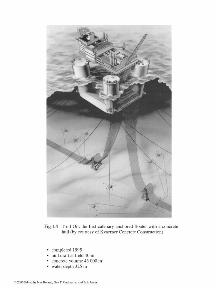
• completed 1995• hull draft at field 40 m• concrete volume 43 000 m3
• water depth 325 m
Fig 1.4 Troll Oil, the first catenary anchored floater with a concretehull (by courtesy of Kvaerner Concrete Construction)
© 2000 Edited by Ivar Holand, Ove T. Gudmestad and Erik Jersin
1.3 Development of the concrete material
When the Ekofisk tank (completed 1973) was designed, the highest strength class allowedaccording to Norwegian Standard was used, namely B 450 with a cube strength (in present units)of 45 MPa, now denoted C 45. Economy favoured a continuous increase of concrete strengthgrades, in particular because cylindrical and spherical shapes were preferred. These needscontributed strongly to the development of high strength/high performance concretes. The strengthgrades in recent structures are, for comparison, about C 80–85. The increase has been madepossible by a steadily increasing level of knowledge accumulated through experience and research.(Moksnes and Sandvik, 1996), (Neville and Aïtcin, 1998), (Moksnes and Sandvik, 1998).
Important factors contributing to the improvements of concrete qualities are:• development of a high strength cement• well controlled aggregate grading• admixtures, in particular superplasticisers and retarders• strict quality assurance procedures The mechanical properties of high-strength concrete differ in many ways from those of traditionalconcrete. Thus, traditional design procedures for reinforced concrete cannot be extrapolated tonew strength classes without a thorough study and relevant modifications. To avoid unnecessaryrestrictions to the application of high-strength concrete, the extended knowledge must beimplemented as rules for high-strength concrete in standards and codes of practice (Section 1.6).
1.4 Design
1.4.1 Preliminary design
Offshore concrete platforms are constructed inshore, floated to a deep-water site for deck-mating and towed to their operation positions offshore. This construction procedure impliesthat the structures must be hydrodynamically stable under many different conditions.Moreover, dynamic response is important in temporary stages as well as at the operating stage.Such requirements necessitate that geometrical external shapes as well as weights andrigidities (and hence thicknesses) are reasonably well approximated in the preliminary design,and that the detailed analyses mainly serve to specify ordinary reinforcement and prestressingsteel. In the preliminary design, basic understanding of structural mechanics and traditionalshell theory, and experience from similar structures play an important role, but computeranalyses may be also used in this phase.
1.4.2 Global analysis
The first designs of the Condeep structures were based on simple, classical shell calculations as
© 2000 Edited by Ivar Holand, Ove T. Gudmestad and Erik Jersin
described under preliminary analyses above. However, the intersections between the differentshell elements introduce irregularities, and the wave loads and other loads introduce variousforces in addition to the hydrostatic ones. Such facts call for more advanced methods of analysis.
The structural analyses have mainly been based on a linear theory of elasticity, and since themid-seventies on the use of large finite element programs. The largest finite elementcalculations may involve more than one million degrees of displacement freedoms and requirethe use of supercomputers (such as CRAY YMP/464 that has been used for the largestanalyses) (Brekke, Åldstedt and Grosch, 1994) (Galbraith, Hodgson and Darby, 1993).
1.4.3 Postprocessing. Dimensioning
The offshore platforms are subjected to a large number of loading conditions during theconstruction, tow-out, installation, operation and removal phases. Large hydrostatic pressuresdominate during deck-mating, while wave, current and wind loads dominate during theoperation phase. To permit the handling of all relevant load cases, a number of basic load casesare selected, from which the actual load cases with load factors for the relevant limit state,possible amplification factors, etc; may be obtained by linear scaling and superposition. Toutilize the huge amount of data from the finite element analysis in an efficient dimensioning ofthe reinforced concrete sections of the structure, a post-processor that is specially developedfor the purpose is needed (Brekke, Åldstedt and Grosch, 1994).
The strength of the reinforced concrete is checked point-wise by comparing the stressresultants with the strength in the same point. The strength evaluation relies on semi-empiricaldesign formulae, mainly based on reduced scale experiments on beams and column elements,and is taking into account cracking and other non-linear effects. The design formulae arespecified in codes and standards, but have also been supplemented by special procedures in thepost-processors (Brekke, Åldstedt and Grosch, 1994). Refinement of the methods is still goingon (Gérin and Adebar, 1998).
1.5 Construction methods
Offshore concrete platforms are constructed inshore, and vertical walls have mainly beenconstructed by slipforming. Slipforming has also been extended to be used for non verticalwalls, variable thicknesses and variation of diameters and cross section shapes as usuallyneeded in the shafts. The slipforming method requires a careful control of the concreteconsistency in order to avoid flaws in the concrete surfaces, thus requiring an intimateinteraction between material technology and construction procedure.
When the concrete structure is completed, it is floated to a deep-water site for deck-matingand towed to the operation position offshore. The production hence also includes challengingmarine operations in narrow fjords.
© 2000 Edited by Ivar Holand, Ove T. Gudmestad and Erik Jersin

1.6 Rules and regulations
1.6.1 Government regulations
Design and construction of offshore structures must, like structures onshore, follow rules thatbasically are laid down by the government that has the sovereignty of the area in question, e.g. in:
USA: United States Department of the InteriorUK: Department of Energy: Statutory Instruments SI 289 1974 The offshore
installationsNorway: Norwegian Petroleum Directorate Norwegian Petroleum Law with Regulations
and Guidelines (NPD, latest version applies).
For the design work in Norwegian waters the following regulations are of particular relevance:• Regulations relating to safety, etc. to Act No. 11 of March 22nd 1985, relating to the
petroleum activities
• Regulations relating to loadbearing structures in the petroleum activities including:* Guidelines to regulations* Guidelines concerning loads and load effects* Guidelines relating to concrete structures
• Regulations relating to the licensee’s internal control in the petroleum activities on theNorwegian continental shelf
• Regulations relating to implementation and use of risk analyses in the petroleum activities,with Guidelines.
As for structural concrete, Norwegian Petroleum Directorate’s “Regulations relating to loadbearing structures with Guidelines” are mainly based on Norwegian standards; see alsoSection 1.6.2 and Chapter 5.
1.6.2 Standards
In many countries, government regulations use the “reference to standards” principle,implying that requirements to safety of structures is considered to be satisfied if specifiedstandards are followed. Thus, standards play an important role for offshore structures. Relevantstandards are, for instance:
• Canadian standard CSA S474–94 Concrete Structures. Part IV of the Code for the Design,Construction, and Installation of Fixed Offshore Structures. ISSN 0317-5669. June 1994.
• ISO standard 13819 Part 3 (to appear, will cover the entire engineering process for offshoreconcrete structures). For design, NS 3473 is referred to as a standard that covers relevantconditions (Leivestad, 1999).
• Norwegian Standard NS 3473 Concrete Structures. Design Rules. 4th edition 1992 (inEnglish), 5th edition 1998 (English edition in print).
© 2000 Edited by Ivar Holand, Ove T. Gudmestad and Erik Jersin

• Norwegian Council for Building Standardisation (1999), Specification texts for building andconstruction, NS 3420, Oslo, Norway, 2nd edition 1986, 3rd edition 1999.
Other documents may play a similar role, e.g. ACI 318–95, saying in the introduction: “The codehas been written in such a form that it may be adopted by reference in a general building code...”
The European prestandard (Eurocode 2, 1991) covers concrete structures in general, butsays explicitly that it does not cover offshore platforms.
Standards are in general not mandatory documents. Similarly, they may also be used outsidethe country or region where they were issued. As an example, the Norwegian standard forconcrete structures was used for the concrete platform on the Hibernia field, Newfoundland,Canada. The reason why the Norwegian standard was preferred was mainly that the operator(Mobil) was well acquainted with this standard from previous projects in the North Sea.
1.6.3 Certification. Classification companies
Control and approval of offshore installations is regulated by national government authorities.The third party role of classification societies in this activity differs (Andersen and Collett, 1989).
The most active classification societies in offshore activities are Lloyd’s Register and DNV,which may be described briefly as follows: • Lloyd’s Register is the world’s premier ship classification society and a leading independent
technical inspection and advisory organisation, operating from more than 260 exclusivelystaffed offices worldwide and served by 3,900 technical and administrative staff.
• Det Norske Veritas (DNV), Oslo is an independent, autonomous foundation established in1864 with the objective of safeguarding life, property and the environment. DNV has 4,400employees and 300 offices in 100 countries. DNV establishes rules for the construction ofships and mobile offshore platforms and carries out in-service inspection of ships andmobile offshore units.
1.6.4 Company specifications
Codes and standards are often not sufficient as technical contract documents. Thus, oil companiesoften choose to issue their own, more detailed, company specifications. Such specifications mayalso prescribe safety requirements in addition to those given in rules and regulations. An exampleof such a specification is NSD 001, issued by Statoil, a Norwegian oil company.
1.6.5 Development of codes and standards
Codes and standards are subject to a continuous scrutinizing and updating to be abreast of thetechnical development. Many actual decisions are, however, taken in a pre-standardizationphase, where the new knowledge is digested in discussions in an international environment.Important organizations in this role are:
© 2000 Edited by Ivar Holand, Ove T. Gudmestad and Erik Jersin
• fib: International Federation for Structural Concrete (established 1998 by merging FIP andCEB)
• ACI: American Concrete Institute• RILEM: International Union of Testing and Research Laboratories for Materials and
Structures.
1.7 Quality assurance
The highly automated analyses by using finite element methods and dimensioning by post-processors have their pit-falls. Thus, comprehensive schemes for quality assurance areimplemented to avoid errors in analysis and design, including simplified checks of results ofthe global analysis, mainly equilibrium checks. A manual issued by the Norwegian oilcompany Statoil recommends that the simplified preliminary analyses discussed above aresystemized in such a way as to also serve the purpose of a rough check of the results of thedetailed analyses (Gudmestad, Holand, and Jersin, 1996).
The need for quality assurance procedures is well illustrated by the Sleipner accident. Thegravity base structure of the Sleipner A platform is a traditional Condeep platform placed at amoderate depth of 82 m in the North Sea. The first concrete hull built for this purpose spranga leak and sank under a controlled ballasting operation in Gandsfjorden outsideStavanger, Norway, on 23 August 1991 (Jakobsen, 1992). It was rebuilt and placed in positionin 1993.
1.8 Durability
The first concrete platform was placed in the North Sea in 1973. Since then the behaviour ofthese structures has been investigated thoroughly by means of inspection and instrumentationprogrammes. In addition, data from maintenance and repair reports are available. Based onsuch data, the durability of offshore concrete structures has been studied by a working groupappointed by FIP (FIP 1996). The conclusions of this group are, directly quoted: • the concrete offshore platforms provide full operational safety• they show a very high durability level• they do not require costly maintenance and repair operations• their effective lifespan has been underestimated and their 20 years initial design life can be
greatly protracted The document has been based on an inquiry answered by:
• The Norwegian Petroleum Directorate• Oil companies• Certifying authorities• Contractors and consultants
© 2000 Edited by Ivar Holand, Ove T. Gudmestad and Erik Jersin
Similar conclusions are found in (Ågnes, 1997), (Moksnes and Sandvik, 1998), (Bech andCarlsen, 1999) and (Helland and Bjerkeli, 1999).
The FIP report also contains recommendations for design, construction and inspection practice.
1.9 Competitiveness
In spite of good experience with concrete structures, they will not be competitive for alloffshore projects. A few essential arguments for the choice of a concrete structure, because ofcost efficiency, are listed below (Ågnes, 1997): • Topside weight. Heavy topsides can be accomodated on a concrete substructure.• Storage. Oil and stable condensate can be stored in concrete cells.• Durability and maintenance. Concrete is favourable when long life-time is desired.• Seabed conditions. On firm soils the concrete platform rests perfectly by its own weight. On
soft soils long skirts provide an efficient solution.• Collision strength. Concrete is robust to local damage.• Motion characteristics of floaters. Concrete platforms offer better characteristics because of
larger displacement.• Ice infested areas. Concrete may be designed to resist ice forces.• Local content. Large parts of the plain construction work can be carried out by unskilled
labour under competent guidance. Cost competitiveness is also discussed in (Collier, 1997) and (Michel, 1997). Marine concretestructures for the future are discussed by showing several options by Olsen (Olsen, 1998) andby Iorns (Iorns, 1999).
1.10 Removal. Demolition. Recycling
It is assumed that all future offshore concrete platforms shall be removed from site afterdecommisioning, except, perhaps, in rare cases. The decommisioning will usually start byrefloating of the platform. All concrete platforms need a ballasting system, for ballasting to aproper draught, during production and tow-out and final positioning on site. In recent cases(for Condeep platforms since Statfjord B 1978) the ballasting system has also been designed tobe used for refloating. Even Platform Removal Manuals have been produced during the designphase in some cases. In spite of this, the refloating is no straightforward operation and willrequire extensive studies of safety precautions during the operation, including possiblestrengthenings. Problems encountered are, for example, related to penetrations by conductors.
A re-use on another site is generally unrealistic, and the next step will therefore bedemolition and preferably reuse of reinforcement steel and crushed concrete (Olsen andHøyland, 1998) (Høyland and Maslia, 1999). For the monotower platform Draugen and thefloating unit at Heidrun, removal and demolition studies have been performed. ConcretePlatforms for re-use have, however, also been discussed (Stead and Gudmestad, 1993).
© 2000 Edited by Ivar Holand, Ove T. Gudmestad and Erik Jersin

1.11 Spin-off effects
The technology developed for the offshore concrete structures has had a number of spin-offeffects for onshore or near-shore construction technology. The following know-how andanalysis tools for advanced technologies are mentioned, with examples of use for other typesof structures:
Know-how on: • high performance concrete (sub-merged tunnels, any concrete structures designed for long-
term durability)• high-strength normal-weight concrete (long-span bridges)• high-strength lightweight aggregate concrete (long-span bridges, floating bridges)• complex slip-forming with change of thickness and change of cross-section shape (towers,
silos)• marine operations in open sea (complex marine transfer and tow operations)• marine operations in coastal waters (floating bridges, submerged tubular bridges)• underwater soil mechanics (submerged tunnels)• evaluation of accidental actions (industrial plants). Software for: • finite element analyses (irregular box-shaped bridges)• dynamic analyses of structures (towers, bridges built by cantilevering techniques)• static and dynamic wave force analyses (floating bridges, submerged tubular bridges)• pre-processors and post-processors for structural design (bridges, other complex
structures). The examples illustrate that the offshore concrete platforms have brought the total concretedesign and construction technology a substantial step forward, a fact that can be utilized also inrelated applications of the technology. (Olsen, 1999), (Andrews and Bone, 1998).
References
Ågnes, R. (1997) Concrete for Marine Applications. CONCRETE a feasible option foroffshore construction. Two-day International Conference, IBC Technical Services,Aberdeen, May 1997.
Andersen, H.W. and Collett, J.P. (1989) Anchor and Balance. Det norske Veritas 1964–1989.J.W.Cappelens Forlag A.S.Oslo.
Andrews. J. and Bone, D. (1998) The specification of concrete for coastal defence and marineworks. Concrete, April 1998. pp. 24–26.
© 2000 Edited by Ivar Holand, Ove T. Gudmestad and Erik Jersin

Bech, S. and Carlsen, J.E. (1999) Durability of high-strength offshore concrete structures. 5th
International Symposium of High Strength/High Performance Concrete Structures. Eds.Holand, I. and Sellevold, E.J.Sandefjord, Norway, 1999. pp. 1387–1394.
Brekke, D.-E., Åldstedt, E. and Grosch, H. (1994) Design of Offshore Concrete StructureBased on Postprocessing of Results from Finite Element Analysis (FEA), Proceedings ofthe Fourth International Offshore and Polar Engineering Conference, Osaka, Japan.
Brown, P. and Nygaard, C. (1997) New Generation TLP. CONCRETE a feasible option foroffshore construction. Two-day International Conference, IBC Technical Services,Aberdeen May 1997.
Chabot, L. (1997) Spar structures—Steel versus concrete. CONCRETE a feasible option foroffshore construction. Two-day International Conference, IBC Technical Services,Aberdeen May 1997.
Collier, D. (1997) Cost competitive concrete platforms—Innovative solutions for today’smarket. CONCRETE a feasible option for offshore construction. Two-day InternationalConference, IBC Technical Services, Aberdeen May 1997.
Eurocode 2 European Prestandard ENV 1992–1–1. (1991): Design of concrete structures.CEN 1991 (under revision 1999 for transformation to EN, European Standard).
FIP (1996). State of the Art Report—Durability of concrete structures in the North Sea. SETO,London.
FIP (1998) Awards for Outstanding Structures. XIII FIP Congress 1998, Amsterdam.
Fjeld, S. and Morley, C.T. (1983) Offshore concrete structures in Handbook of StructuralConcrete. Eds. Kong, F.K., Evans, R.H., Cohen, E. and Roll, F., Pitman, London.
Galbraith, D.N., Hodgson, T. and Darby, K. (1993) Beryl Alpha—Condeep GBS Analysis.SPE 26689. Offshore Europe Conference, Aberdeen September 1993.
Gérin, M. and Adebar, P. (1998) Filtering analysis output improves the design of concretestructures. Concrete International. December 1998. pp. 21–26.
Gudmestad, O.T., Holand, I. and Jersin, E. (1996) Manual for Design of Offshore ConcreteStructures. Statoil, Stavanger, Norway.
Gudmestad, O.T., Warland, T. Aa. and Stead, B.L. (1993) Concrete Structures for developmentof offshore fields. Journal of Petroleum Technology, August 1993. pp. 762–770.
Helland, S. and Bjerkeli L. (1999) Service life of concrete offshore structures. Offshore WestAfrica ’99 Conference and Exhibition, Abidjan, Ivory Coast.
© 2000 Edited by Ivar Holand, Ove T. Gudmestad and Erik Jersin

Holand, I. and Lenschow, R. (1996) Research Behind the Success of the Concrete Platforms inthe North Sea. Mete A. Sozen Symposium. ACI SP-162. Farmington Hills, Michigan, pp.235–272.
Høyland, K. and Maslia, J. (1999) Removal and recycling of high strength offshore concretestructures. 5th International Symposium on Utilization of High Strength/High PerformanceConcrete. Sandefjord, Norway.
Irons, M.E. (1999) Low-Cost Ocean Platform Construction—A Point of view. ConcreteInternational. December 1999.
Jakobsen, B. (1992) The Loss of the Sleipner A Platform. Proceedings of the Second (1992)International Offshore and Polar Engineering Conference. San Francisco 1992.
Leivestad, S. (1999) ISO Standard for fixed concrete structures. 5th International Symposium ofHigh Strength/High Performance Concrete Structures. Edited by Holand, I and Sellevold,E.J., Sandefjord, Norway, 1999. pp. 421–426.
Michel, D. (1997) The advantages of floating concrete construction. CONCRETE a feasibleoption for offshore construction. Two-day International Conference, IBC TechnicalServices, Aberdeen May 1997.
Moksnes, J. (1990): Oil and Gas Concrete Platforms in the North Sea—Reflections on twoDecades of Experience. Durability of Concrete in Marine Environment, An InternationalSymposium Honoring Professor Ben C.Gerwick, Jr., University of California.
Moksnes, J. and Sandvik, M. (1996) Offshore concrete structure in the North Sea. A review of25 years continuous development and practice in concrete technology. Odd E.GjørvSymposium on concrete for marine structures. New Brunswick, Canada.
Moksnes, J. and Sandvik, M. (1998). Offshore concrete in the North Sea—Development andpractice in Concrete Technology. Concrete under severe conditions 2. E & FN Spon,London, pp. 2017–2027.
Neville, A. and Aïtcin, P.-C. (1998) High performance concrete—An overview. Materials andStructures, Vol. 31, pp.111–117.
Norwegian Council for Building Standardisation, NBR (1998), Concrete Structures, Designrules. NS 3473, 4th edition, Oslo, Norway, 1992 (in English), 5th edition 1998 (EnglishEdition in print).
Norwegian Council for Building Standardisation, NBR (1999), Specification texts for buildingand construction”, NS 3420, Oslo, Norway, 2nd edition 1986, 3rd edition 1999.
Nygaard, C. (1997) Concrete—A potentially schedule competitive option. CONCRETE a
© 2000 Edited by Ivar Holand, Ove T. Gudmestad and Erik Jersin

feasible option for offshore construction. Two-day International Conference, IBC TechnicalServices, May 1997.
O’Flynn, M. (1997) Gravity base structures and jack-up platforms. CONCRETE a feasibleoption for offshore construction. Two-day International Conference IBC Technical Services,May 1997.
Olsen, T.O. and Høyland, K. (1998) Disposal of concrete offshore platforms—Is recycling ofmaterials an acceptable option? Sustainable Construction: Use of Recycled ConcreteAggregate. Thomas Telford, London.
Olsen, T.O. (1998) Marine concrete structures. Concrete under severe conditions 2. E & FNSpon, London, pp. 1596–1605.
Olsen, T.O. (1999) New generation marine concrete structures. 5th International Symposium ofHigh Strength/High Performance Concrete Structures. Edited by Holand, I. and Sellevold,E.J.Sandefjord, Norway, 1999. pp 91–98.
Stead, B.L. and Gudmestad, O.T. (1993) A concrete platform for re-use in variable waterdepths, with varying topside functions and weights. 1993 OMAE—Vol. 1, OffshoreTechnology. ASME.
© 2000 Edited by Ivar Holand, Ove T. Gudmestad and Erik Jersin

2 Concept definition and project organization
Ove T.Gudmestad, Statoil
2.1 Objectives
The objectives of Chapter 2 are to contribute to: • give an overview of the requirements for design of offshore concrete structures.• convey the experiences from prior projects, to those having special interest in offshore
concrete structures.• promote and enhance the confidence in offshore concrete structures.• give an overview of how to design a concrete platform, an overview which can also be
suitable reading for students.
2.2 General description of an offshore concrete structure
Prior to any further discussion regarding design of an offshore concrete structure, referencesare made to Figures 2.1 and 2.2, which show typical fixed and floating concrete structures,respectively. It is of special importance, for further insight, to recognise the names of thevarious elements of the structures.
For several typical offshore concrete concepts, floating stability is not achieved if one (ormore) of the compartments are damaged and flooded with water. This is representing a line ofthinking in design which is not common in connection with ship-design. It also means thatstructural design must be done with particular care. For fixed bottom founded concretestructures the importance of floating stability applies during the floating phases only, as thestructures cannot sink after being installed offshore.
Floating concrete structures have to be designed with sufficient safety against sinking, incase compartments facing open sea would be filled with water during operations at the field.
For design of concrete structures the requirements of Section 18 of the NorwegianPetroleum Directorate’s “Regulations relating to load bearing structures in the petroleumactivities” should be given special attention:
The structural system, details and components shall be such that the structures: a) show optimum ductile properties and little sensitivity to local damageb) are simple to makec) provide simple stress paths with small stress concentrationsd) are resistant to corrosion and other determinationse) are suitable for simple condition monitoring, maintenance and repairf) are removable.
© 2000 Edited by Ivar Holand, Ove T. Gudmestad and Erik Jersin

Fig. 2.1 Gravity Base Structure (Gullfaks C platform in North Sea)
© 2000 Edited by Ivar Holand, Ove T. Gudmestad and Erik Jersin

Fig. 2.2 Tension leg platform
© 2000 Edited by Ivar Holand, Ove T. Gudmestad and Erik Jersin

2.3 Project phases
During design of an offshore structure it is worthwhile noticing that the work is performed inseveral project phases with an increasing degree of detail (Fig. 2.3). During the first phase, forexample, the advantages of various structures is assessed, and comparisons are made for fielddevelopments using various types of structures. As part of the work during the detail designphase, which forms part of the construction phase (not shown in Fig. 2.3), the detailedcalculations are made. For concrete structures this includes geometry drawings, rebardrawings, rebar bending schedules, etc. More detailed description of the work in the variousphases are given in the following sections; see also Fig. 2.3 and Appendix A.
Fig. 2.3 Project Phases for Design of Marine Structures
2.4 Rules and regulations
Offshore concrete structures are to be designed according to national rules and regulations (seeSection 1.6 and also (NPD, 1992), (NBR, 1998) and (NBR, 1999).
© 2000 Edited by Ivar Holand, Ove T. Gudmestad and Erik Jersin

2.5 Project management
2.5.1 Project planning
(a) The objective of project planningDesign of an offshore structure should be regarded as a project, i.e. a set of tasks to beaccomplished within a specified period of time, and with limited resources. Also, there must bea project organisation with responsibility for execution of the project task.
A project is a link in a chain, where the effectiveness and quality, among other things, dependon the interaction between the various links; project employer, project and supplier, Fig. 2.4.
The purpose of the project planning is thus to: • distribute responsibility, authority and tasks• achieve high quality of the project results• manage resources, time and cost and control the use of them• reduce the use of double work and unproductive/unnecessary project tasks. (b) Control activities
To achieve the objectives of the project planning, it is important to establish necessary controlactivities to ascertain the fulfilment of the objectives (Fig. 2.5).
Fig. 2.4 Description of a project as a link in a chain
Fig. 2.5 Control activities
© 2000 Edited by Ivar Holand, Ove T. Gudmestad and Erik Jersin
The control activities are: • to establish goals• establish an activity plan to reach the goals• control the execution of the project in accordance with the plan• follow up the execution• identify and analyse plan deviation• plan and perform improvements and, if necessary, take care of corrective activities. Design of offshore structures will be a sub-project within a major investment project. Aninvestment project can be characterised by a high exposure of cost, combined with highuncertainties. The uncertainties are partly linked to the investment cost for facilities and partlyto future incomes.
The development of an investment project will last for years, with several decision points(milestones). The project is therefore sub-divided into project phases as discussed in theprevious sections of this chapter.
2.5.2 The project control basis
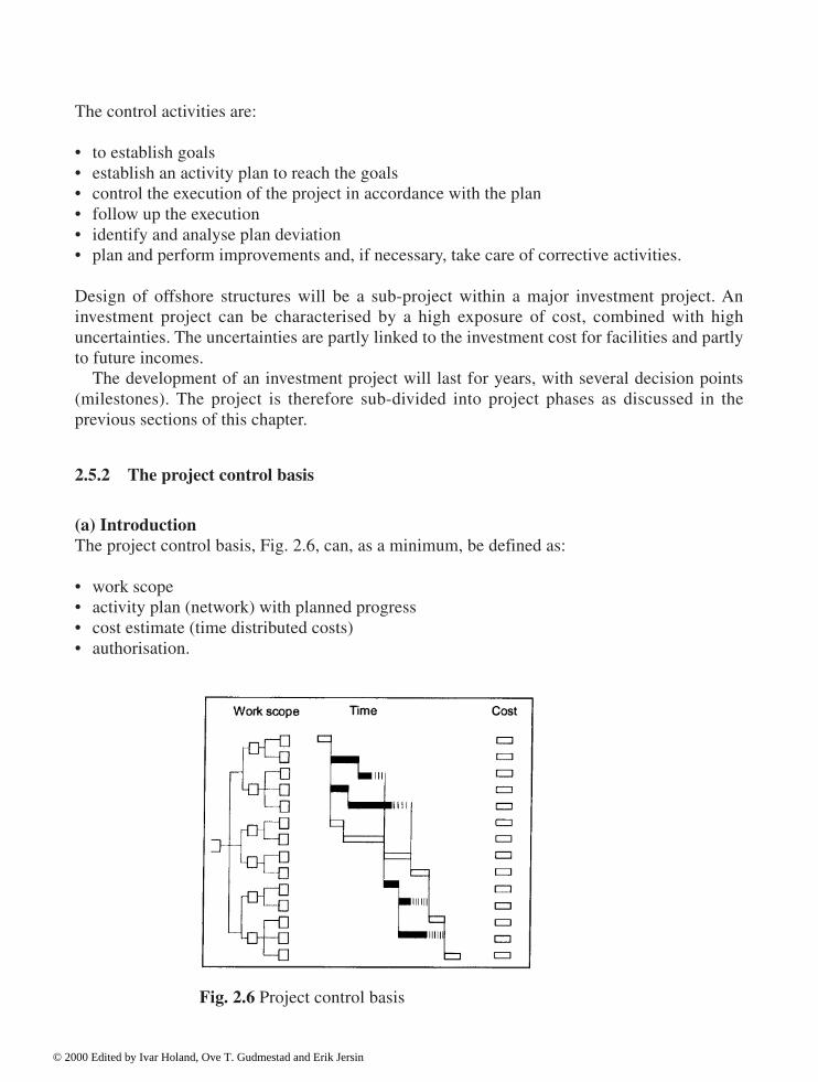
(a) IntroductionThe project control basis, Fig. 2.6, can, as a minimum, be defined as: • work scope• activity plan (network) with planned progress• cost estimate (time distributed costs)• authorisation.
Fig. 2.6 Project control basis
© 2000 Edited by Ivar Holand, Ove T. Gudmestad and Erik Jersin

The control basis should be compiled before the start of each of the phases in the investmentproject.
In addition, the project control basis should define the control parameters influencing theproject objective.
The control parameters should be consistent through all the project phases, and should beupdated when new information gives grounds for changing the parameters.
The result of the planning process: milestones, resource planning and cost phasing establishan execution plan as control basis for the next project phase. (b) Project breakdown structureThe project control basis should be broken down according to a standard cost coding system,enabling easier planning and control of the project, such that deviations can be detected andcorrective actions implemented.
The cost coding system should make allowances for various requirements, depending on theproject phase, i.e. if it is in an early planning phase or in a later project phase (execution).
The cost coding system is designed such that planning data for various project alternativescan be compared and analysed in all the project phases.
The cost coding system will be the foundation for systematically feeding back of experiencedata and for compilation of time schedules and estimates.
The cost coding (Fig. 2.7) accommodates the following three hierarchy structures: • Physical Breakdown Structure• Standard Activity Breakdown• Code of Resource.
The combination of physical extent, standard activity and resource type gives the foundationfor a standard preparation of plans, cost estimates and experience data.
The work scope is broken down into work packages (Fig. 2.8) in the execution/developmentphase.
Fig. 2.7 Standard cost coding system
© 2000 Edited by Ivar Holand, Ove T. Gudmestad and Erik Jersin

The breakdown into work packages should take the following into consideration: • organisation and ownership• contract philosophy• supplier marked availability• work complexity• interface internally and externally in the project• method of assessment and control of workmanship. In the concept definition phase the cost coding of the control basis, in accordance with theStandard Cost Coding System, should be carried on from the project development phase.
During the execution phase, the project control basic is structured in work packages. Thecontrol basis is broken down into a level below work packages (planning level 3).
The project defines requirements to suppliers’ systems. The requirements should be relatedto the interface between the project and additional vendors, enabling the individual vendors touse their own systems. The control basis should be possible to aggregate on all levels. (c) Execution planExecution plans for the project shall be prepared with relations and limitations to: • time• resource• cost. Detailing of the execution plans is dependent on the level of ambitions and on requirementwith respect to uncertainties.
The execution plan is part of the project agreement between client and project, and relates to theproject’s main plan, which forms the basis for project development decision. At all times mustprogress, milestone achievements and other activities during execution of the project be related tothe project’s main plan. The execution plans are thus important references for control of the project.
Fig. 2.8 Work breakdown structure (AFE= Authorization for Expenditure)
© 2000 Edited by Ivar Holand, Ove T. Gudmestad and Erik Jersin

The execution plans should include: • scope of work (including technical specifications)• progress plans (including externally given milestones)• resource plans• cost estimates (including budgets). The relation between scope of work, time, resources and cost are linked to the lowest level(planning level 0) in the project’s Work Breakdown Structure (WBS) see Fig. 2.8. (d) Scope of workThe client is responsible for a proper definition of the project’s goals, and to ensure that thegoals are understood by all parties involved.
The main goal of a project is always to strive for cost/benefit-effect (i.e. to maximise theprofit on the invested capital).
The correlation between the various sub-goals for the project and the main goals can be difficultto understand. The project control parameters must therefore be clearly defined, to assure that allinvolved have got a mutually agreed understanding of common goals, project tasks, assumptions/frame conditions in the entire chain from client to project and to contractor/supplier.
Project agreement. The project goal and the overall control parameters shall be documented ina project agreement. The project agreement shall describe goals and tasks, assumptions andframe conditions, plans and estimates, responsibilities and authorities. The document isprepared by the client.
Contracts. The need for mutual goals and understanding of project scope, assumptions andframe conditions also applies to the supplier for those parts of the project for which he is beinggiven responsibility.
During contract formulation (see also Section 2.8), and following-up of the contract, it mustbe assured that the project’s requirements to management and control systems is met so thatproject goals can be reached.
By setting contract requirements for quality management and control to contractors/suppliers, the possibility of preventing negative deviations are increased. (e) ScheduleThe overall progress plan forming the basis for execution of the project, is called “MasterControl Schedule”.
During project execution, deviations will occur, hereby creating the need for schedulerevisions, called Current Control Schedule.
The work packages in the project containing volume, time and cost shall be split into workorders, CTRs (cost, time, resource estimates), by the contractor/supplier.
Schedules are normally presented in two ways: A network (Fig. 2.9) containing necessaryinformation about work sequences and logic for the aim of analyses, as well as a Gantt-diagram for presentation purposes of the project, (Fig. 2.12).
© 2000 Edited by Ivar Holand, Ove T. Gudmestad and Erik Jersin

Network. The activities’ dependence on each other should be modelled in a project network(Fig. 2.9). The level of detailing and complexity in the network model will be determined bythe project’s complexity, magnitude and requirements for quality and follow up. The networkdefinition comprises of: • activity dependence with type of bonding• early start/finish• late start/finish• delays/overlaps.
Analysis and presentation (Gantt-diagram). The final schedule, with built in slack andoverlapping activities, should be drawn up and determined from what will overall give the bestproject economy. The likelihood of meeting the ending date or in-between milestones shouldalso be determined (Fig. 2.10).
Fig. 2.9 Project network
Fig. 2.10 Analysis of progress schedule
© 2000 Edited by Ivar Holand, Ove T. Gudmestad and Erik Jersin

The time schedule should be presented in a Gantt chart (Fig. 2.12) with duration, start, finishand slack for each activity. When the work scope of each activity is not clearly stated in theplan, then it should be indicated separately.
The activities’ mutual dependence on each other, the network structure and the anticipateduse of resources in each activity, should all be well documented. (f) Resource planningResource planning (Fig. 2.11) and follow up should be formalised in a system. A Code ofResource is to be used for each system where it is considered necessary, with respect to costestimation, duration analysis and physical progress planning.
Guidelines for allocation of resources should be worked out and used for planning,registering and follow up of the physical progress.
Each activity’s minimum duration should be defined, together with the required resourcesand the resulting costs at the same time as constraints from such factors as safety andenvironmental concerns are satisfied. The use of resources and funds as a function of durationshould generally be determined.
(g) Cost estimate requirementsCost estimates. The cost estimate is an approximation of the final project costs, based on factsand reasoning. The estimate should be worked out in accordance with the relevant cost codingsystem for the project phase. Presumptions for a cost estimate, such as: • scope of work/technical solution• inflation, exchange rates• uncertainty• specific planning competence should be documented.
Fig. 2.11 Resource planning
© 2000 Edited by Ivar Holand, Ove T. Gudmestad and Erik Jersin
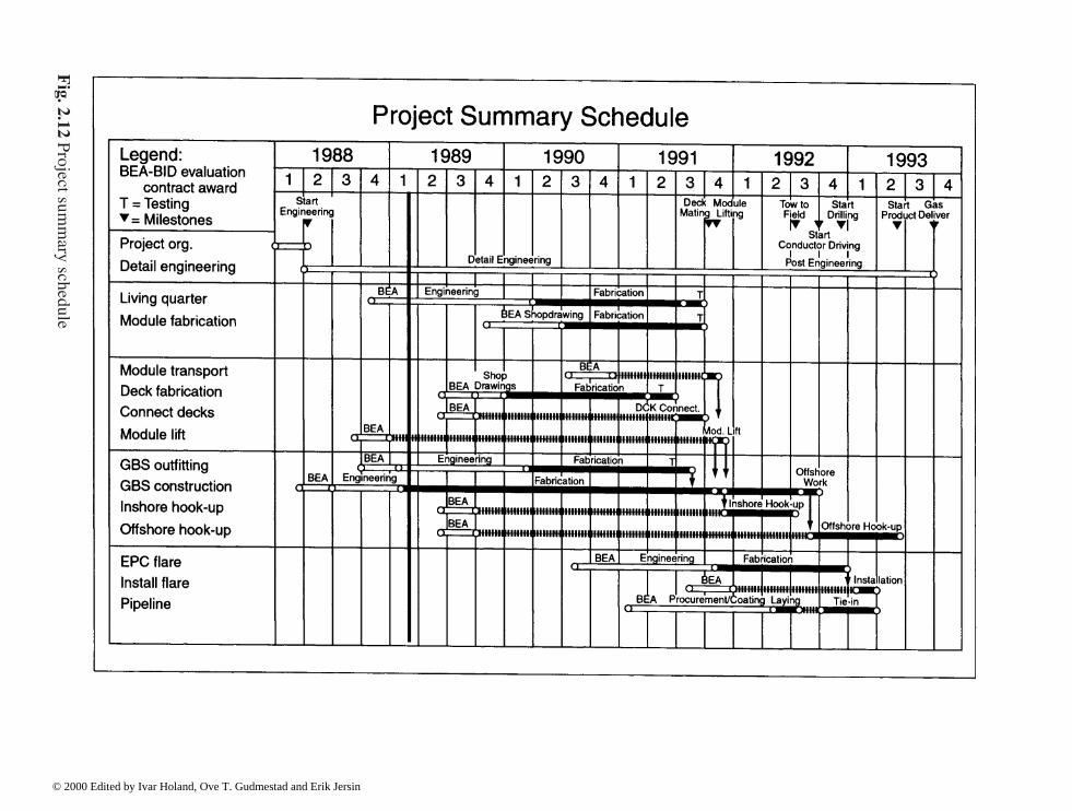
Fig. 2.12 P
roject summ
ary schedule
© 2000 Edited by Ivar Holand, Ove T. Gudmestad and Erik Jersin

Specific planning competence is the project foundation, as defined in the project baseline. Theestimation method will depend on how many of the four variables: • scope• complexity• productivity• price are declared.
Estimation methods (Fig. 2.13) The estimation method will be selected based on the projectphase reached, level of technical definition and access to experience data.
During the early project phases when the extent and complexity of technical definition islimited, the synthetic method will be used, i.e. estimation by relations and factors fromexperience data, main parameters and technical description. The analytic method, i.e.estimation of the all contributing elements directly, where the technical concept is well definedand the scope of work and complexity can be determined, is used in later phases of the project,where the contributing factors can be specified and estimated in detail.
When new concept solutions are proposed, the analytic method will also apply for early phases.The analytic method shall always be used for project development, concept definition and
project execution phases.
Uncertainties. Estimates shall present how much resources are needed to perform the projector how much is the cost of the project.
A cost estimate is an expression of what we believe the project will cost. We assume that thebasic parameters do not change in the course of the project. The estimate is as such anuncertain value of cost and, if calculated, based on the most possible objective criteria, statingapplied norms of estimation, and on professional judgement. The project is estimatedreflecting the established work breakdown structure (WBS) and the chosen execution plan.
Assumptions for cost estimation method and the unit cost (productivity figures, unit ratesetc.) shall be documented.
Fig. 2.13 Estimating methods
© 2000 Edited by Ivar Holand, Ove T. Gudmestad and Erik Jersin

The estimation norms are so set that under given circumstances there should be equalprobability for result over as under the individual unit rate (50/50 estimate).
An estimate is presented with an expectation value (50/50 estimate, i.e. the value giving thesame probability for over/under-run), min/max values and confidence level.
All four variables; scope, complexity, productivity and price are related to uncertainties andthey should, dependant on method used when estimating, interpretation of available data, etc.,be described by a probability distribution (Fig. 2.14). Simplified, this can be a 50/50 value inaddition to the low/high values.
Requirements for cost estimation and schedule classification. Requirements for costestimation and time scheduling classification is a classification system with definedrequirements to: • basic information, work scope• estimation method• level of detailing• time scheduling• uncertainties analysis, etc.• presentation and documentation formats. The classification requirements shall describe the method for cost estimation and timescheduling, give requirements to technical information needed to perform the planning and theneed for the accuracy of the estimate (Fig. 2.15).
Fig. 2.14 Cost estimation uncertainty
© 2000 Edited by Ivar Holand, Ove T. Gudmestad and Erik Jersin

Cost estimates are refined during the course of the project to reflect the additional detailavailable. A progression of five types of construction cost are normally used; order ofmagnitude, conceptual, preliminary, definitive and control.
(h) Risk assessmentProject risks shall be identified, analysed and responded in order to maximise the results ofpositive events and to minimise the consequences of adverse events. Risk identificationconsists of determining which risks are likely to affect the project and documenting thecharacteristics of each. In project context, risk identification is concerned both withopportunities (positive outcome) as well as threats (negative outcomes). The identified riskitems shall be quantified to assess the range of possible project outcomes. Risk responsedevelopment involves defining enhancement steps for opportunities and responses to threats. (i) BudgetBudget Estimate. A budget is established administratively through a management decision. Thebasis for the decision can be a cost estimate, but the budget itself is not linked with uncertainties.The budget is a known, deterministic figure. The budget may have different meanings: • a cost frame for the project to be kept within• an expression of the project’s expected total cost• a target figure for the project organisation to reach at. The different understandings of the budget reflect the extent of authority the project has got inspending money.
Fig. 2.15 Cost estimate in different phases
© 2000 Edited by Ivar Holand, Ove T. Gudmestad and Erik Jersin
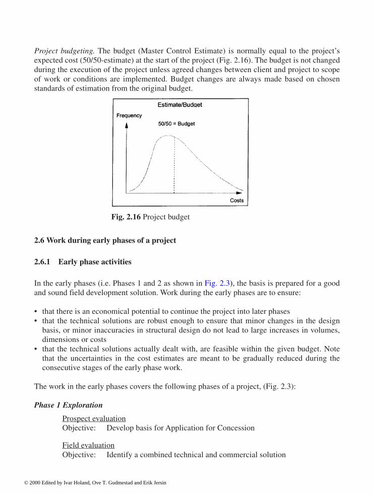
Project budgeting. The budget (Master Control Estimate) is normally equal to the project’sexpected cost (50/50-estimate) at the start of the project (Fig. 2.16). The budget is not changedduring the execution of the project unless agreed changes between client and project to scopeof work or conditions are implemented. Budget changes are always made based on chosenstandards of estimation from the original budget.
2.6 Work during early phases of a project
2.6.1 Early phase activities
In the early phases (i.e. Phases 1 and 2 as shown in Fig. 2.3), the basis is prepared for a goodand sound field development solution. Work during the early phases are to ensure: • that there is an economical potential to continue the project into later phases• that the technical solutions are robust enough to ensure that minor changes in the design
basis, or minor inaccuracies in structural design do not lead to large increases in volumes,dimensions or costs
• that the technical solutions actually dealt with, are feasible within the given budget. Notethat the uncertainties in the cost estimates are meant to be gradually reduced during theconsecutive stages of the early phase work.
The work in the early phases covers the following phases of a project, (Fig. 2.3): Phase 1 Exploration
Prospect evaluationObjective: Develop basis for Application for Concession
Field evaluationObjective: Identify a combined technical and commercial solution
Fig. 2.16 Project budget
© 2000 Edited by Ivar Holand, Ove T. Gudmestad and Erik Jersin

Phase 2 Project developmentFeasibility study
Objective: Reach a decision whether the actual field is commercial and prepare aReport of Commerciality
Field development study
Objective: Describe the best economical solution for field development, andprepare a Plan for Development and Operation (PDO) of the field. InNorway This PDO-document is to be submitted to the authorities forevaluation and for final approval in the Parliament.
During the early phases the possibilities of influencing the development solution and theeconomical results of the final product is high. Work done in later phases tends more to focuson details, and the extent of documentation increases.
It is important to put forward requirements of what efforts are needed to ensure that enoughwork is performed, such that: • the results satisfy the requirements of the phase in question• the results are sufficient to start the work in the next phase. As a result of this, a Discipline Activity Model, which describes the required extent of work inthe various phases of the study, will be useful. A typical Discipline Activity Model for an offshoreconcrete structure is included in Appendix A. Note that the Appendix defines the need for analysisin the various phases of the project. Furthermore, it defines how the work shall be quality assured.The Appendix also specifies which reports are to be issued during the various phases.
In all phases, a technical basis shall be developed to serve as a basis for estimates of costsand plans. The technical basis has to build on realistic information about field parameters. Ofparticular importance for production are parameters like: • production volume• number of wells, risers and J-tubes for pull-in of production pipes from subsea wells and
from other fields• weight and layout of the production plant (topsides)• required storage volume. Furthermore, field specific environmental parameters are important for assessment of the fielddevelopment solution. Of special importance is information regarding: • water depth• wave height and sea current• earthquake conditions (in areas with potential earthquakes)• ice conditions (when relevant)• geotechnical conditions.
© 2000 Edited by Ivar Holand, Ove T. Gudmestad and Erik Jersin

Fig. 2.17 Input to cost estimating programme for estimate in the prospect evaluation phase ofthe development
© 2000 Edited by Ivar Holand, Ove T. Gudmestad and Erik Jersin

Fig. 2.18 The design process is an iterative process
© 2000 Edited by Ivar Holand, Ove T. Gudmestad and Erik Jersin

2.6.2 Selection of concrete structures
Concrete structures are relevant for quite a number of various field developments. It should benoted that: • fixed concrete structures with short skirts were developed especially for the hard seabed
conditions and the large production plants needed for the North Sea during the 1970’s to1980’s
• fixed concrete structures with long skirts were developed especially for the soft soilconditions into and in the Norwegian Trench (Tjelta and others, 1990)
• floating concrete structures have been developed over a long period in the 1980’s and1990’s. A concrete tension leg platform with concrete foundations have been installed at theHeidrun field. For oil production at the Troll field a concrete floater with chain mooringshave been installed.
2.6.3 Design of concrete structures in the early phases, examples
In the Prospect Evaluation Phase, data gained by experience are used to evaluate the potentialsof new blocks. The work can be simplified by the use of PC-based tools. An illustration ofinput data needed is shown in Fig. 2.17, see also Appendix A (Discipline Activity Model forDesign of Offshore Concrete Structures).
In the Field Evaluation Phase there is a search for one development solution which showsprofitability. Even if detailed technical studies are not performed, it is of importance that thepersons performing the job have enough experience such that: • the actual solution is prepared thoroughly to assure that the cost estimate is realistic• the actual solution has not got too many extra reserves built in such that the economical
potential is lost and further work is stopped. In the Feasibility Study Phase the technical solutions shall be ranked. Uncertainties in the costestimates are to be reduced to ± 30%. In this phase concrete structures are compared withalternative solutions. This represents a special challenge to the concrete designers and forcesthem to establish innovative solutions. Both oil companies, relevant engineering groups andcontractors are to be involved.
Notice that the development work to obtain a competitive concept is interactive, as shown inFig. 2.18: • constructive solutions are chosen• load calculations are made and structural analyses are performed• structural design is carried out This is done for the various activities of a development project, including:
© 2000 Edited by Ivar Holand, Ove T. Gudmestad and Erik Jersin

• construction• transportation• installation• operation• removing. Since the objective of the Feasibility Study Phase is to rank the actual technical solutions, thetechnical work has to be performed thoroughly. In particular the need for Quality Assurance isemphasised. This is done by engaging highly experienced persons to participate in the studiesand to evaluate the technical reports.
In the Feasibility Study Phase it is also relevant to consider new concepts with largepotential, which so far only have been developed to a lower degree of detail. Special programsfor technology development can be initiated to qualify development solutions with muchpotential.
In some countries where the technology development not yet has reached Western Europeanlevels, there is particularly large interest in offshore concrete structures, due to the fact thatconcrete structures can be built by means of: • local resources (sand, cement, rebars etc.)• extensive use of local work force. Furthermore, the construction of concrete structures may lead to: • development of local infrastructure (production of cement and reinforcement)• development of engineering companies and technical know-how. In a Field Development Study the work in the Feasibility Study Phase is carried to a higherdetailed level. A more comprehensive technical study is required, to ensure that the costestimates (~~20% accuracy) submitted to the authorities, and which also forms the basis for theauthorities’ decisions, are valid also for the successive phases of the development.
Appendix A (Discipline Activity Model for Design of Offshore Concrete Structures)indicates the level of detail for technical studies relating to an offshore concrete structure.Special attention shall be made to the fact that an acceptable Plan for Development andOperation (PDO) which is submitted to the authorities after the finalisation of the FieldDevelopment Study Phase, requires good insight in: • the environmental loads and other loads like ship collisions, etc.• the geotechnical conditions• the interface between the substructure and the production plant (topsides), including the
decision of whether transfer of the topside to the platform shall take place inshore or belifted on at the offshore site.
To ensure that the correct concept is chosen also implies that:
© 2000 Edited by Ivar Holand, Ove T. Gudmestad and Erik Jersin

• choice of concrete quality must be made (to assure a robust structure it is suggested thatnormal density concrete of quality C70 represents the upper limit for this stage)
• choice of routing of flowlines from wells, risers and J-tubes. Large risers for gas aregenerally routed inside a dry shaft or outside the structure until a location below waterline
• development of criteria for potential use of jack-up drilling platforms must be made. This decides the layout of the foundation of the concrete structure.
Furthermore it shall be noted that tank-testing can be relevant at this stage, to assure thequality and the feasibility of the structure, see also NPD’s “Regulations relating to loadbearingstructures”, paragraph 30.
In case the PDO-report does not open up for choices of concrete structures, it will normallynot be relevant to suggest that concrete structures should be chosen in the later phases of thefield development.
2.7 The concept definition phase
2.7.1 Concept report
The goal of the concept definition phase (the concept evaluation phase) is to work out a ConceptReport, which in turn forms the basis for the detail design and the fabrication contract.
The concept report shall describe the concept in sufficient details to avoid major changes inthe successive detail design phase. Furthermore, the concept shall be robust enough toaccommodate minor technical changes in the design basis. The concept shall also have built ina certain “forgiveness” to allow for minor inaccuracies. It is, furthermore, needed to emphasisethat weight control shall be an important parameter for those working with the topsides, andmajor changes in the topsides weight must be avoided. For concrete structures it is also ofimportance that uncertainties in weight, due to the amount of reinforcement and to waterabsorption in concrete, are included in the concept definition phase. This is to assure that theplatform has acceptable floating stability during all temporary phases, and for floatingconcrete structures also during the operation phase.
The concept report shall also describe important principles for the detail design, and theseprinciples are assumed to be unchanged throughout the construction phase. For instance, theextent of vertical post tensioning of the concrete shafts represents a principle which is definedduring the concept definition phase. Other principles of importance which are suggested to beincluded in the concept definition phase are: • that the geometry of the concrete is correct. Changes to the geometry (e.g. wall thickness)
could lead to large consequences in the detail design phase• that the concrete quality C70 (for normal density concrete) or LC60 for LWA-concrete (light
weight aggregate concrete) are the maximum values applied during the concept definitionphase. This will give the project some reserves in highly stressed areas. It is, for example,particularly unfavourable if the amount of reinforcement is significantly increased during thelater phases due to the fact that shell walls are too thin in the early phases. It is also very costly
© 2000 Edited by Ivar Holand, Ove T. Gudmestad and Erik Jersin

to build a structure where there is barely room enough for placing the required amount ofrebars as rebar placement and compaction of the concrete then would become very demanding
• that all openings towards the sea have double barriers in case of damage• that the lower dome of the drillshafts shall not be penetrated if a conductor-pipe is lost
during the construction phase. This applies to the cases when the structure is floating withno damage stability and the lower dome is exposed to dropped objects
• that (during the concept definition phase) it should be aimed at avoiding membrane tensionin the concrete walls throughout the section when the structure is to be exposed to the designwave (ultimate limit state with load coefficient of 1,3). This will contribute to a robuststructure with only minor cracks and an acceptable fatigue life.
2.7.2 Technical work
The technical work during this phase will be comprehensive, as indicated in Appendix A(Discipline Activity Model for Design of Offshore Concrete Structures); see also (Fjeld andMorely, 1983) and (Tjelta, Aas, Hermstad and Andenæs, 1990). Some special problems whichshall be evaluated, are as follows: • load analysis with assessment of whether special phenomena may be present due to the
geometry of the structure• the need for model testing• geotechnical conditions and geotechnical stability during installation and operation• analyses of all phases during construction and installation, specially emphasising floating
stability and requirement for stability in case of damage• designing of all critical sections, with calculation of section forces and moments, including
amount of rebars and detailing of the need for pre stressing (see Chapter 3 and Chapter 5).For structures of the Condeep type, the geometry in the tri-cell areas and other joints are tobe designed in detail.
• element analyses of critical sections like top of shaft (see Chapter 4)• the safety of the platform’s mechanical systems e.g. ballast systems and the oil company’s
mechanical systems (flowlines from wells, risers, oil storage system etc.)• choice of bulkhead sectioning and analyses of floating stability during operation. For
floating platforms, specially emphasising how the platform can be designed with acceptablespare buoyancy to allow for some topside load increases in the later phases.
For fixed and floating structures, respectively, the following calculations shall be discussed indepth:
Fixed concrete structures: • Floating stability, including level of ballast water in all essential stages of fabrication• Global wave forces, including the requirements for calculation of forces in the shaft base
(Morison wave load analysis with Stokes 5th order wave theory)
© 2000 Edited by Ivar Holand, Ove T. Gudmestad and Erik Jersin

• Dynamic calculations, including demonstration of the natural response period if “springing”and “ringing” (transient dynamic response) can give a substantial contribution to the globalwave forces
• Geotechnical evaluation, both of geotechnical stability as well as of soil structure interactionin conjunction with dynamic calculations, including analysis of soil pressure distributionunder the foundation during various load applications Furthermore the possibility of soilerosion shall be assessed.
Floating concrete structures: • Floating stability, including estimate of the level of ballast for all essential stages of
fabrication and operation• Detailed hydrodynamic calculations of wave forces as well as global responses. In addition,
it should be noted that certain stages in connection with fabrication can lead to specialdesign forces in parts of the structure
• Dynamic design, including identification of the various natural response periods where“springing/ringing” can contribute to a substantial part of the global wave forces
• Geotechnical calculations in connection with the mooring systems• Analyses of the water tightness of the structure to assure that the structure can be safely
operated throughout its entire design life. The oil company normally gets most of this work performed by experienced consultants/contractors. Concerning development of offshore concrete structures, it is essential that thecontractors tendering for construction are allowed to develop competitive structures adopted totheir own construction facilities. Thus, the oil company can obtain competitive bids fromseveral competent tenderers.
2.7.3 Quality assurance and verification
It is assumed that the work performed during the concept development phase has been subjectto the proper quality assurance, see Appendix A (Discipline Activity Model). The principlesdescribed here are used both by the oil company and the external contractors involved.
In addition it is relevant to use external consultants to perform verification of parts of thedocumentation. For this phase it is recommended to channel all communication related toverification through the oil company (see Chapter 7).
There is also a need for a rough risk analyses during the concept definition phase to identifywhether the concept has built in major risks during the phases of construction or operation related to: • loss of human life• damage to the environment• loss of values. Thus, risk reducing efforts can be incorporated. Special emphasis should be made to focus onthe following risk elements during the construction phase:
© 2000 Edited by Ivar Holand, Ove T. Gudmestad and Erik Jersin

• risk of falling objects• risk of uncontrolled ingress of water due to pipe failure or malfunctions of the ballast system• risk of collisions• risks during towing and installation. In addition, the accidental design loads applied in the operation phase are to be determined.
2.7.4 Schedules and budgets
An important part of the concept definition phase is to establish detailed schedules and budgetsfor the development project.
2.7.5 Competence requirements
The concept report represents the final basis for a successful performance of a developmentproject. Consequently, it is of the highest importance that all parties involved use their mostexperienced engineers and make them responsible for the project’s concept evaluation phase.
2.8 Project organization phase
2.8.1 Introduction
The project Organisation Phase represents an intermediate phase inbetween the phases ofconcept definition and construction. Note that detail design is part of the construction phase.
During the project organisation phase the construction work (fabrication) is prepared. Severalfundamental principles of technical nature have therefore to be clarified during this phase.
2.8.2 Contract
A contract for the construction phase has to be established in this phase. Included herein ischoice of type of contract. The following definitions can be used for important tasks during theconstruction phase:
E Engineering work (detail design)P ProcurementC ConstructionI Installation
The contract for construction can include one or more of these tasks. For construction ofoffshore concrete structures the normal contract form has been to select one contractor for thewhole work, i.e. an EPCI-contract. In some cases, though, the oil company has separated the
© 2000 Edited by Ivar Holand, Ove T. Gudmestad and Erik Jersin

Main Mechanical Outfitting work (MMO-work) from this contract and placed that part of thescope with a separate mechanical contractor. This split of contract implies that the oil companyhas to co-ordinate the concrete and mechanical contractors.
In other cases the detail design is also assigned to a separate design contractor. Theadvantage is that more contractors can tender for construction after the completion of the detaildesign work. The drawback is that this leaves the oil company as responsible for assuring thatthe detail engineering is performed properly and that the design is constructable, and issued indue course. Any changes may lead to claims for costly change orders.
Most of the arguments lead to the preference of one EPCI-contract for detailed design andconstruction of an offshore concrete structure. Such a contract puts the responsibility on onecontractor. The oil company has in advance qualified the tendering contractors. The judgementregarding qualifications are based on technical competence, experience and financial strength. Ofspecial importance is to have documented that the project can be performed according to schedule.
With such a comprehensive contract format as described above, it is of paramountimportance that the contract clarifies essential relations between the oil company and thecontractor. This applies to inter alia: • list of specifications according to which the work shall be performed• required detailing of contractor’s documentation and work, including detailed specifications
of the basis for the work and requirements for co-operation with the oil company. Especially,it is regarded important that the oil company has the right to take direct control over theamount of reinforcement (payment by unit rate)
• requirements for efficient organisation of contractor’s work, to ensure that safety, environment,cost and progress are secured. Included in this is clear definitions of “who to do what” incontractor’s organisation, and of which subcontractors be accepted and how they are managed
• requirements to contractor’s technical know-how, including requirements to the involvedpersons. Special requirements must be set to contractor’s technical management and theirco-ordination of the technical work
• requirements to the contractor’s internal control• requirements to co-operation between the contractor, the oil company and the consultant
performing the third party verification, including agreement with the contractor as to howcomments from the third part verification shall be duly incorporated
• procedures for reporting of results, progress, problems and deviations• agreement of milestones for revisions, and agreement of the oil company’s right to claim
revisions as and when it finds it necessary. This also applies to revisions of subcontractors• agreement on commercial relations. Special emphasis is to be made such that the contractor shall follow the Concept Report issuedby the oil company during the concept definition phase. It is assumed that the oil company hasestablished a thorough concept report which includes: • robustness to withstand minor changes in the design basis, for instance increased weight of
the topsides within ±5%• “forgiveness” to avoid major changes to the concept, if minor omissions are made in the
concept definition phase which lead to changes in dimensions and weight.
© 2000 Edited by Ivar Holand, Ove T. Gudmestad and Erik Jersin
This does, however, not mean that safety margins shall be applied beyond the requirements ofthe national rules and standards. Arrangements must be laid down in the contract to ensure thatall changes to the concept report shall be agreed by the oil company and treated according tospecially agreed procedures.
During contract preparation and negotiations it is important that the oil company’s projectgroup has high technical expertise and long administrative experience.
2.8.3 Quality assurance plan
During the Project Organisation Phase the oil company must prepare a plan for how to performquality assurance of the work during detail engineering and construction. As to procedures andsome available tools for quality assurance, see Chapter 6.
2.8.4 Verification plan
A plan for verification has to be developed. The plan shall include: • description of the extent of work for the verification, emphasising special critical areas of
the structure• requirements to the oil company’s own verification of contractor’s work, with description of
the follow-up work during the detail design and construction activities• requirements to the contractors’ internal quality control and surveillance• working methods and work description valid for the consultant performing the third party
verification• requirements for prompt implementation of the results from the verification. The choice of strategy for external verification is of special importance. The oil company musthave direct contact with the third party verification consultant. Payment should be madeaccording to spent hours within agreed limitations. Chapter 7 details two models for externalverification: 1. the oil company submits the results from the verifying consultant to the contractor2. company is managing the verification, but the verification consultant communicates
mainly directly with the contractor. Regardless of which model is followed, the verifying consultant is obliged to follow a tightschedule not to delay the progress of the contractor. The oil company must take all formaldecisions in case disagreements arise between the contractor and the third party verificator.The oil company should also be the single point contact with the authorities and the partners.
© 2000 Edited by Ivar Holand, Ove T. Gudmestad and Erik Jersin

2.8.5 Preparation for the organization of the construction phase
During the process of preparing for a development project, project organisations are built upwithin the oil company and the contractor. The oil company is to ensure that both his ownpersonnel and those of the contractor have the acceptable competence. This is partly done byspecifying competence requirements for every leading position in the project. Every leadermust have thorough knowledge of the technical content of the activity he is meant to lead. It ispresupposed that the project is organised to assure openness with respect to technicalquestions, and that the requirements for quality in performance is characterising the dialoguesand feed backs. No project philosophy which suppresses technical problems should be allowed
In offshore field development projects, key persons who have worked during earlier phasesin the same project should be brought in, so that continuity in the technical work is maintained.All staff in a project must agree to the project’s goals and the procedures applied to reach thesegoals.
References
Fjeld, S. and Morely, C.T. (1983) Offshore Concrete Structures, in Handbook of StructuralConcrete. Eds Kong, F.K., Evans, R.H., Cohen, E. and Roll, R, McGraw Hill.
Norwegian Council for Building Standardisation, NBR (1999) Specification texts for buildingand construction, NS 3420, Oslo, Norway, 2nd edition 1986, 3rd edition 1999.
Norwegian Council for Building Standardisation, NBR (1998), Concrete Structures, Designrules. NS 3473, 4th edition, Oslo, Norway, 1992 (in English), 5th edition 1998 (Englishedition in print).
Norwegian Petroleum Directorate, NPD, Rules and Regulations for Petroleum Activities, Newedition issued every year by the Norwegian Petroleum Directorate, Stavanger, Norway.
Norwegian Petroleum Directorate, NPD (1992) Regulations relating to loadbearing structuresin the petroleum activities, stipulated by the Norwegian Petroleum Directorate, Stavanger,Norway.
Tjelta, T.I., Aas, P.M., Hermstad, J. and Andenæs, E. (1990) The skirt piled Gullfaks Cplatform installation. Paper OTC 6473. Proceedings Offshore Technology Conference, pp.453–462, Houston, Texas.
© 2000 Edited by Ivar Holand, Ove T. Gudmestad and Erik Jersin

3 Simplified analyses
Tore H.Søreide, Reinertsen Engineering
3.1 Introduction
This Chapter deals with simplified calculation schemes for use in the engineering of marinestructures, as an alternative to complex computerized techniques for response analysis. Themain objective of the development of analytical techniques is to come up with a tool for earlyestimates of dimensions, prior to the start of the process of detail engineering. Furthermore,simplified methods, either by hand or based on spreadsheets, are also useful for the control ofthe complex scheme of global response analysis.
The complete analysis set-up is shown below in Section 3.2, which demonstrates that forsimplified response analysis there is a need both for global and local models for capacity control.
As a basis for the evaluation of calculation methods, the loads are to be classified inaccordance with the characteristics of their impact on the structural system. Section 3.3 gives abrief introduction into basic dynamics, which is also relevant when deciding the type ofanalysis in the global response model.
Section 3.4 presents simplified analytical techniques to be used for fixed gravity basedplatforms. The global response is calculated by modal techniques which keep the number ofparameters to a minimum.
The analysis schemes for floating marine structures are given in Section 3.5, where catenaryanchored as well as tension leg platforms are dealt with. Formulas are depicted for the analysisof first order wave effects, ringing effects as well as hydrostatic stability. Section 3.6 considersship impact and presents methods for global response analysis.
Section 3.7 handles second order geometric effects in design, including shafts and planarwalls as well as cylindrical cell walls. The geometric effects from finite rigid body rotations offloating structures are also illustrated. The problem areas dealt with for floating marinestructures are also relevant for fixed structures during fabrication, tow and installation,especially the hydrostatic stability calculations, built-in forces and skew ballast.
3.2 Analysis activities
3.2.1 Analysis for detail design
This section describes the process of analysis during detail design. The purpose of thispresentation is to show at which stages in engineering simplified methods are relevant as asupplement to complicated finite element response models.
© 2000 Edited by Ivar Holand, Ove T. Gudmestad and Erik Jersin

Fig. 3.1 illustrates the complete scheme for analysis and capacity control. The term analysishere means the global response analysis for the specific design situations. The load effects arestresses, stress resultants and displacements. The analysis models cover all stages offabrication, mating, tow, installation and operation. The finite element model of the raft is to becoupled to the topside model for response analysis of the completed structure.
The design activity includes the combination of results for the individual basic load cases aswell as load combinations for capacity control. The input both for analysis as well as forcontrol is taken from the Design Basis document (see Chapter 5).
Fig. 3.2 gives the analysis procedure normally applied for the load effect from first orderwaves. A panel model is generated from the wet part of the raft (below mean water). Regularwaves with unit amplitudes and different directions and periods form the basis for thestochastic extreme value estimation of stress resultants. The response from the stochasticanalysis is now represented by a regular wave with the same response value, often termed thedesign wave. This procedure enables the phase between section forces to be simulated, thoughin the form of one single regular wave.
The process of design wave evaluation ends up strictly with one design wave per responseparameter. In practical design, however, emphasis is normally given to group design waves forseveral responses, ending up with a limited number of basic wave load cases. The panelpressures and rigid body accelerations from the hydrodynamic model go into the global stressanalysis model, by which a quasi-static analysis scheme is followed.
3.2.2 Simplified analysis scheme
As a supplement to the rather complex global analysis of load effects, the simpler analyticalformulas can be applied in order to produce early estimates of section forces andcorresponding dimension controls. Basic structure mechanics knowledge is essential for thecreation of the analytical models, where rigid body dynamic effects should also be included. Alimited number of governing load situations are implemented, and insight into the responsecharacteristics of the structural system is vital for safe selection.
For the global analysis, hand calculations can be used, or a frame model is made of the raft.The stiffness and mass characteristics of the topside are to be implemented, as well as possiblefoundation characteristics. For gravity base marine structures of moderate height, the dynamicmotions are normally of minor importance, so that a pure static response analysis is sufficient.
The above calculations provide the static and dynamic stress resultants created by the globalload carrying behaviour. Local effects from water pressure such as membrane and bendingstresses in shaft and cell walls, are calculated either by analytical shell theory, or alternativelyby a limited finite element model. In the case of such local finite element models being used,the boundary of the element mesh with load or displacement restrictions is to be put in somedistance from the critical sections under consideration.
Fig. 3.3 illustrates the flow of calculations by means of a simplified procedure. A frame modelis established and the topside connection is included. At the same time the process of local finiteelement analyses is set, with input from the global calculations of the boundary forces.
Load combinations, as well as the estimates of design section forces come in subsequently,in accordance with the Design Basis document and possible specifications from the operator.
© 2000 Edited by Ivar Holand, Ove T. Gudmestad and Erik Jersin

Fig. 3.1 Analysis and capacity control by computer program© 2000 Edited by Ivar Holand, Ove T. Gudmestad and Erik Jersin
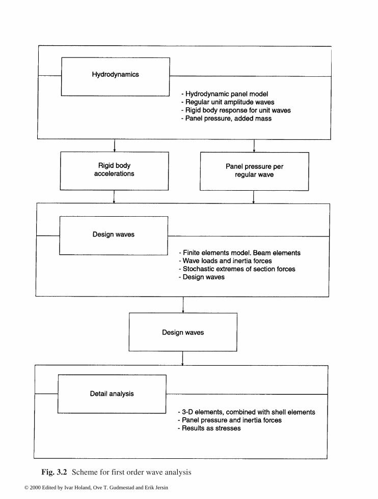
Fig. 3.2 Scheme for first order wave analysis
© 2000 Edited by Ivar Holand, Ove T. Gudmestad and Erik Jersin

Fig. 3.3 Simplified response analysis and design
© 2000 Edited by Ivar Holand, Ove T. Gudmestad and Erik Jersin

3.3 Classification of load effects
3.3.1 System analysis
Prior to the activity on final analysis models, a system analysis is to be made as a basis for thesubsequent selection of analysis models. The main objective of this evaluation of responsecharacteristics is to sort load effects into respectively static and dynamic classes of response.The characteristics of structural changes during fabrication and installation and the evaluationof load effects must produce relevant response models for all stages. It is convenient toseparate the displacements of the system into rigid body motion and deformation modes,respectively.
The system analysis is to be documented. Experience from larger projects proves that allpersonnel involved in the engineering team benefit from a presentation of the system analysisas a basis for their considerations concerning design load situations. A description of thestructural load carrying behaviour also makes the control of the global analysis results easierfor the engineering personnel.
3.3.2 Load effects
Once the structural system is determined, the different loads are to be categorized inaccordance with their influence on the structure. This will reveal if static response can beapplied, or a dynamic model is needed. As a basis for this evaluation of responsecharacteristics, the natural frequencies of the system should be made available, either by anelement analysis, or alternatively, from simple analytical estimates.
As an example of categorization of loads, reference is made to the Norwegian PetroleumDirectorate (NPD) regulations, see Section 1.6.1. The following load types normally implystatic response analysis: • Dead load (permanent load)• Ballast (variable load)• Prestress• Hydrostatic pressure (permanent load)• Tide (variable load)• Current (variable load)• Mean 10-min. wind (variable load)• Built-in forces (permanent load)• Imposed deformations (deformation load, temperature, shrinkage). For the cases of wave load response and for impacts, dynamic effects are to be included.Dynamic wave analysis also implies the consideration of the fabrication stages, for which thedeformation modes may be flexible with low natural frequencies close to the highest wavefrequencies (0.5–0.2 Hz).
© 2000 Edited by Ivar Holand, Ove T. Gudmestad and Erik Jersin

The upper and lower outer limits for the dynamic response characteristics are as follows: Stiffness dominated
The frequency of the load is low when compared to the modal frequencies of the structure:
KX= R(t) (3.1) Inertia effects are neglected, as for a fixed gravity base platform in a permanent situation. Inertia dominated
The load frequency is high when compared to the natural frequencies, resulting in dominancefrom inertia forces in the dynamic equilibrium:
M X =R(t) (3.2) This is often the situation with impact loads. For a catenary anchored floater, all six rigid bodymotions may be inertia dominated, while for a tension leg platform, the surge and swaydirections of motion are inertia dominated.
Between the two above outer limits, stiffness, mass and damping govern the load effects.For local stress control, static analysis can normally be used.
3.4 Gravity base structures
3.4.1 Model for global response analysis
This section deals with a simplified model for global response analysis of gravity baseconcrete structures, which combines the contribution of the rigid element displacement of thestructure and the beam effect of the shafts. The actual load effects are displacement andacceleration of the deck, and alternatively, beam moment and shear at the base of the shaft.
Fig. 3.4 points to several factors that need to be evaluated prior to running the globalanalysis model. These factors include: stiffness characteristics, mass motion and soil damping,as well as the deformation characteristics of the caisson cell walls that influence the degree ofclamping at the base of shaft. The deck connection to the top of shafts affects also the momentand the shear force in the shafts. A total understanding of load distribution in the deck and thestructure is necessary. Interaction with the surrounding water shall be accounted for. Fig. 3.5gives an illustration of load, mass and damping that are included in the dynamic model.
© 2000 Edited by Ivar Holand, Ove T. Gudmestad and Erik Jersin

There are now two ways to perform a simplified global analysis: either by a simplified elementmodel (beam elements for shafts and shell elements in the caisson), or by hand calculations.
The following procedure gives a rough indication of these approaches: A. The analyses should include all critical phases such as construction, towing, installation
and operation.
B. For each phase an eigenvalue analysis is performed with due consideration of water mass.
C. If the natural period of the structure is substantially below the load period interval, aquasi-static calculation is performed by neglecting the mass contribution.
D. When masses are believed to influence the behaviour of a slender structure they are takeninto account.
Further illustrations are based on simple hand calculations.
Fig. 3.4 Simplified model
© 2000 Edited by Ivar Holand, Ove T. Gudmestad and Erik Jersin

Fig. 3.5 Global dynamic effects
© 2000 Edited by Ivar Holand, Ove T. Gudmestad and Erik Jersin

Simplified equations for one degree of freedom:
Modal stiffness
(3.3)
Modal mass:
(3.4)
Eigenfrequency:
(3.5)
where
�(x) = assumed deformation�,xx = curvaturems = mass of structure including ballast waterma = additional mass from surrounding water.
a. Submerged phasefor deck connection
b. Operation phase
Fig. 3.6 Simplified eigenvalue calculations
© 2000 Edited by Ivar Holand, Ove T. Gudmestad and Erik Jersin
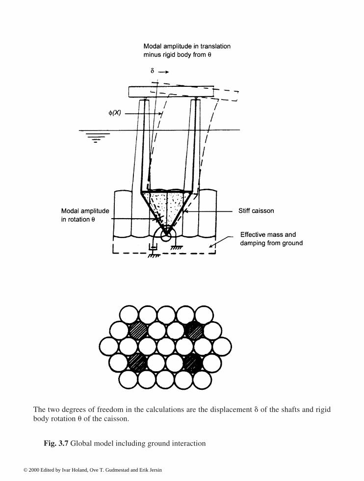
The two degrees of freedom in the calculations are the displacement � of the shafts and rigidbody rotation � of the caisson.
Fig. 3.7 Global model including ground interaction
© 2000 Edited by Ivar Holand, Ove T. Gudmestad and Erik Jersin

Fig. 3.6 shows a model of the submerged phase just prior to coupling the deck to thestructure and also a model in the operation phase. In both models the shafts are assumed to beclamped at the top of the caisson. For the submerged phase, it is necessary to compare thenatural frequency with the wave period at the actual location. In protected water, such as in afjord, the values are somewhere between 2 and 6 seconds. Clement weather is needed forcoupling operations.
In the operation phase the composite action of the deck and the structure is considered. InFig. 3.6b a simply supported connection is indicated between the deck and the shaft (situationjust after coupling). A fixed connection is then established by stressing cables and grouting thespace between the deck panels and the shaft. An indication of the deck stiffness compared tothe shaft stiffness can be obtained by calculating the modal stiffness in the same mode for thedeck and the shaft.
In Fig. 3.7 an alternative global model is shown, where the caisson is assumed to be stiff, butthe stiffness, the mass and the damping are included for the ground.
The general equations for the elements in modal stiffness, mass and damping are:
(3.6)
(3.7)
(3.8)
where:m
s= mass of structure including ballast water
ma
= additional mass of surrounding water
Ck
= damping in structure
ca
= damping from surrounding water.
In relation to equations in Fig. 3.6, Fig. 3.7 includes rigid body displacement of shafts andcaisson. It is appropriate to use a two-degrees of freedom system, where the modal amplitudesare, for example, the rotation of the caisson and the horizontal displacement of the top ofshafts. The displacement pattern with two degrees of freedom may be described by the globalmodes (see Fig. 3.8):
u(x) = � · y for the caisson
for the shafts
© 2000 Edited by Ivar Holand, Ove T. Gudmestad and Erik Jersin

Fig. 3.8 Displacement pattern
The stiffness and mass calculations are then
Stiffness:
Mass: (3.12)
(3.11)
(3.10)
(3.9)
© 2000 Edited by Ivar Holand, Ove T. Gudmestad and Erik Jersin

Horizontal displacement:
u(x)=� · ��(x)+� · �
�(x) (3.16)
where �
�(x) and �
�(x) are the modal functions.
From this comes a 2 x 2 system of stiffness, mass and damping.
Two eigenvalues are obtained from the condition
det (K–�2M)=0 (3.17) and the equivalent eigenvector from
(K-�i2 M) X
i=0 (i=1,2) (3.18)
Simplified calculations of eigenvalues may be done by hand. An alternative method is to use abeam program that is merged to a corresponding element model of the deck. Fig. 3.9 showssuch an analysis of the Condeep platform Sleipner A.
Eigenvalues can be used to study the sensitivity of the structure with regard to assumptionsmade in the analysis. In Fig. 3.10 a sensitivity study has been performed of eigenvalues withregard to variation in deck stiffness, ground stiffness and structure stiffness.
Eigenvectors from the calculations above are the modal displacement pattern. A global loadanalysis with a chosen governing wave can be calculated by hand by “placing” the wave loaddistribution in the modes above. The equations can be solved for each mode. The load effect isthen increased by multiplying it by a dynamic factor.
If the inertia forces are substantial, the acceleration is computed for each mode. If severaleigenforms are used, the total acceleration is calculated as the contribution from eachindividual period where the phase angles are considered. In most cases, the eigenperiods are soshort with respect to the wave period that all the modes can be assumed to be in phase with theloading. The water mass is considered in the inertia forces.
© 2000 Edited by Ivar Holand, Ove T. Gudmestad and Erik Jersin

Fig. 3.10 Eigenperiod as a function of flexibility
Fig. 3.9 Eigenvalue calculations with a beam program
© 2000 Edited by Ivar Holand, Ove T. Gudmestad and Erik Jersin

3.4.2 Models for local load effects
For a Condeep gravity base structure simplified calculations can be performed for most of thestructural parts using shell theories. With reference to Fig. 3.11 this applies to the shaft walls,upper domes, cell walls and lower domes. Common to all the parts is that the dominant loadconsists of compressive normal forces.
(a) Outer cellsFor the outer parts of the lower and upper domes and outer cylinder wall of an outer cell, anaxisymmetric assumption gives a good indication of the sectional forces. Such analyses can bemade by hand, by satisfying the compatibility and equilibrium conditions of the domes, ringbeam and cylinder wall on rotation/moment and displacement/shear force.
Another method is to use an element program modelling the cell and the domesaxisymmetrically. With regard to the choice of element size and type see Chapter 4 that dealsspecifically with cylindrical shells.
Fig. 3.11 Load effects for a simplified analysis
© 2000 Edited by Ivar Holand, Ove T. Gudmestad and Erik Jersin

where
r = middle radius of cylinder wallt = wall thicknessv = Poisson’s ratiop = outer hydrostatic pressure (uniform)le
= elastic length.
Within a distance of le from each edge, the compression force will be determined from a
membrane solution
N� = p · r (3.22) An indication of the local bending effect close to the ring beam can be calculated usingEquation (3.19) with a wall thickness of t=0.60 m and a middle radius of 10 m with acorresponding elastic length of 1.90 m. For thick cylinder walls the above equations must beadjusted to account for the difference between the middle radius and the radius of surfacewhere the load is applied. (b) Inner cellsFor the inner cells, the geometry and the boundary conditions are more complex. Apart fromthe circular walls, some of the caissons also have straight walls. A horizontal beam analogy ismore appropriate for those walls when subjected to one-sided hydrostatic pressure.
For the upper and lower domes on the other hand, an axisymmetric solution givesappropriate sectional forces when the dome is subjected to hydrostatic pressure. Because of thestiffening effect of the surrounding cells it is a good approximation to assume clamping at thering beam, in other words no rotation or translation.
In the unique case of no rotation or displacement at the ring beam, bending of thecylinder wall is characterized by:
© 2000 Edited by Ivar Holand, Ove T. Gudmestad and Erik Jersin

(c) ShaftsFor the shaft the axisymmetric theory can be used to estimate the bending moment and shear atthe junction caisson/shaft. Furthermore, the compressive normal force along the shaft can becalculated from (3.22) with correction for thick shell.
At the boundary condition caisson/shaft, a special analysis is needed to take into account theeffect of the upper domes and the surrounding cells. A local element model by shell or solidelements would be necessary. Forces from earlier global analysis are applied in the model.
During coupling of deck to the shaft, large concentrated forces develop. A finite elementmesh would be required at the interface to evaluate the forces. In these areas a strut and tiemethod of calculation can be useful for design. (d) CastingsIt is not unusual that during detailed design, changes and adjustments occur to the geometrywhich then does not correspond to the global finite element model. An example is concretecastings around mechanical outfittings. These castings affect the structure, but they are nottaken into account in the global analysis.
For such situations a local element model is advisable. Displacements from the globalanalysis are applied to the local model.
In addition to castings inside the structure, similar castings are used outside the platformsuch as around J-tubes and crane footings.
3.5 Floating structures
3.5.1 General
This section reviews the major load effects acting on a floating concrete structure. Thedescription is based on simple models for hand calculations or desk computers.
The action between the raft and the deck is especially important for a floating structure. Thissection will nevertheless deal mainly with the concrete raft and takes into account the effect ofdeck stiffness at the intersection points. With regard to the mass of the deck it is also importantthat, for the hand calculations, the actual weight distribution and weight placement are substituted.
A system analysis with emphasis on global response in the construction and operationphases is considered. The hydrostatic stability calculations are reviewed in addition to thestatic loading. The static and dynamic characteristics are analysed together with criticaldeformation patterns of the raft. This gives an overall indication of inertia forces in thedynamic models including the water mass.
Catenary anchored platforms as well as tension leg platforms are considered.
3.5.2 System description
Design of floating platforms requires the analysis of all construction phases, mating (coupling)of the deck, installation and operational phases. Residual forces from the construction phasescan be important for design.
© 2000 Edited by Ivar Holand, Ove T. Gudmestad and Erik Jersin

As shown in Fig. 3.12, before placement of the deck, the raft has little global bendingstiffness. In the submerged phase, such as during mating, the additional mass from the sea issubstantial. This gives a high natural period (approximately 3 seconds) that could give aresonance effect for short fjord waves. For maximum depth of submergence, the line of actionof the wave is highest. The effects mentioned above can govern the design of the entire raft, notonly due to the high hydrostatic pressure but also due to the global effect.
Fig. 3.13 shows the total picture of the structure system with the deck included. The deckstiffens the raft at the top and cancels the deformations shown in Fig. 3.12. Load distributionbetween the raft and the deck is important in the design of the deck as well as the raft.
For floating structures where large motions are common, it is more appropriate to split theload effect from displacement and deformations in two, namely one set of rigid body modessuperimposed with a set of deformation modes. This is a well established method for theanalysis of structures with large motions. Rigid body modes are dominant in the determinationof the inertia forces, while the deformation modes determine the sectional forces in thestructure.
For static loads, the split mentioned above is easy since the calculation of load effectsfollows the same principle for all modes with regard to rigid body and deformation types. Forboth mode types a modal stiffness is calculated which is then compared with the modal load.
For dynamic loads, the dynamic increase of each individual mode must be included. It isnecessary here to have a model where the contribution of the mass from the structure and the
Fig. 3.12 Raft before deck mating
© 2000 Edited by Ivar Holand, Ove T. Gudmestad and Erik Jersin
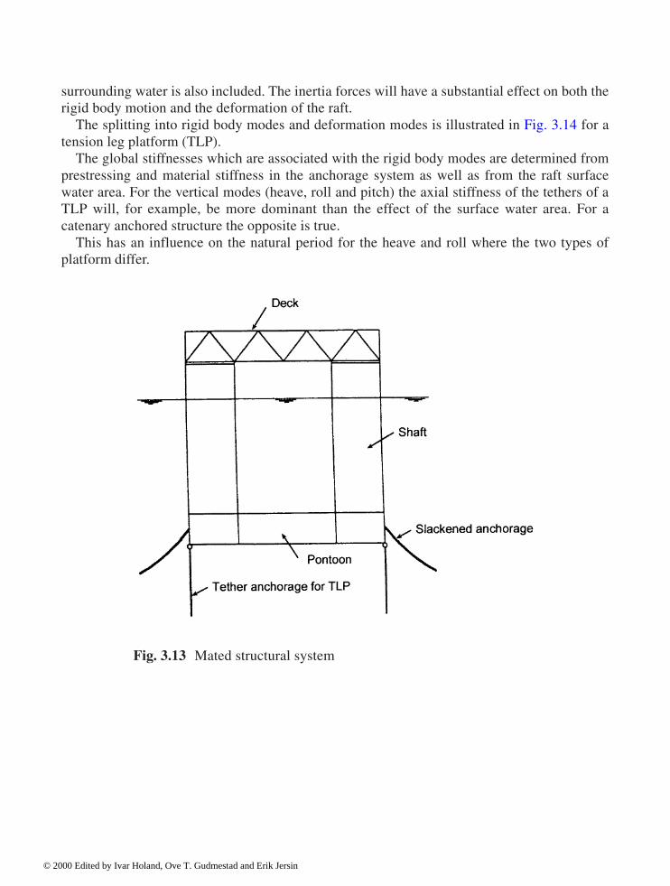
surrounding water is also included. The inertia forces will have a substantial effect on both therigid body motion and the deformation of the raft.
The splitting into rigid body modes and deformation modes is illustrated in Fig. 3.14 for atension leg platform (TLP).
The global stiffnesses which are associated with the rigid body modes are determined fromprestressing and material stiffness in the anchorage system as well as from the raft surfacewater area. For the vertical modes (heave, roll and pitch) the axial stiffness of the tethers of aTLP will, for example, be more dominant than the effect of the surface water area. For acatenary anchored structure the opposite is true.
This has an influence on the natural period for the heave and roll where the two types ofplatform differ.
Fig. 3.13 Mated structural system
© 2000 Edited by Ivar Holand, Ove T. Gudmestad and Erik Jersin

Fig. 3.14 Rigid body mode and deformation mode
© 2000 Edited by Ivar Holand, Ove T. Gudmestad and Erik Jersin
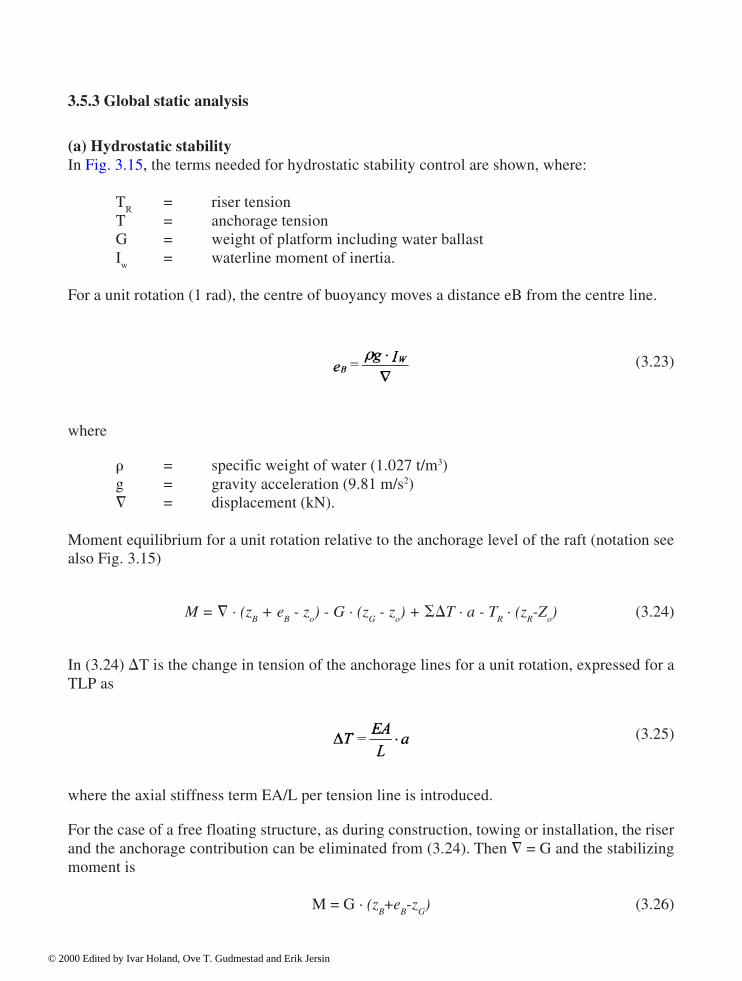
3.5.3 Global static analysis
(a) Hydrostatic stabilityIn Fig. 3.15, the terms needed for hydrostatic stability control are shown, where:
TR
= riser tensionT = anchorage tensionG = weight of platform including water ballastI
w= waterline moment of inertia.
For a unit rotation (1 rad), the centre of buoyancy moves a distance eB from the centre line.
(3.23)
where
� = specific weight of water (1.027 t/m3)g = gravity acceleration (9.81 m/s2)� = displacement (kN).
Moment equilibrium for a unit rotation relative to the anchorage level of the raft (notation seealso Fig. 3.15)
M = � · (zB + e
B - z
o) - G · (z
G - z
o) + �T · a - T
R · (z
R-Z
o) (3.24)
In (3.24) T is the change in tension of the anchorage lines for a unit rotation, expressed for aTLP as
(3.25)
where the axial stiffness term EA/L per tension line is introduced.
For the case of a free floating structure, as during construction, towing or installation, the riserand the anchorage contribution can be eliminated from (3.24). Then � = G and the stabilizingmoment is
M = G · (zB+e
B-z
G) (3.26)
© 2000 Edited by Ivar Holand, Ove T. Gudmestad and Erik Jersin

and
(3.27)
The Z
0 requirement is the stability criterion for a free-floating structure.
For a TLP in operation the tethers are the dominant items for hydrostatic stability.
Fig. 3.15 Hydrostatic stability
© 2000 Edited by Ivar Holand, Ove T. Gudmestad and Erik Jersin

(b) Static rigid body motionThe raft is assumed now as non-deformable and that the stiffness of the anchorage systemdetermines the motion for given loads. As shown in Fig. 3.16 it is convenient to establish theequilibrium equations in the Cartesian co-ordinate system with the origin located in the centreof the anchorage system of the platform. A 6 x 6 stiffness relation is then established:
(3.28)
For a TLP the stiffness in the horizontal modes can be defined from the geometric stiffness
(3.29)
of the tethers:
where Ti is the pretension and L
i length of tether number “i”.
The vertical stiffness in heave and roll will depend on the axial stiffness of the tethers,whereas the contribution of the water surface area is secondary. We get:
(3.30)
where EA/L is the axial stiffness of a tether and Aw the water surface area of the platform.
The expression in (3.28) is linear and does not take into account that the tensile forces in theanchorages change as a consequence of the platform motion. For a TLP where the stiffness ofthe tethers is dominant, the raft will follow an approximately circular path in the vertical planefor sideways motion. For a given horizontal displacement U, the increase in depth will be:
(3.31)
where L is the length of the tether.
© 2000 Edited by Ivar Holand, Ove T. Gudmestad and Erik Jersin

This increase in depth can be in the order of a few metres. This gives a buoyant force that,once more, alters the force in the tether.
(c) Static deformation of raftThis section deals with the deformation mode of the raft under the influence of static loads inorder to obtain the sectional forces in the structure. The deformation pattern shown in Fig. 3.17is a typical example for loads from waves and wind.
Fig. 3.16 Global reference system
© 2000 Edited by Ivar Holand, Ove T. Gudmestad and Erik Jersin

To obtain the deformations and the sectional forces one needs the stiffness of the pontoons,the shafts and the deck. It is also important to get the correct stiffness model of the boundariesbetween the pontoon and the shafts and between the shafts and the deck.
A method using hand calculations to obtain the sectional forces is shown below. Analternative method is to use a beam model in an element program, particularly when differentload situations are to be analysed.
With reference to Fig. 3.18, the virtual deformation figure is chosen with the intention ofcalculating the moments at the boundaries of the pontoon. It is assumed here that we still havea simply supported connection between the top of the shaft and the deck, this assumptionneeds to be re-evaluated for each load situation. Given the pontoon moment as MPON, and � asthe virtual angle at a section with MPON, the internal virtual work, including two pontoons, is:
�Wi=4 · M
PON · �ß (3.32)
Fig. 3.17 Bending deformation of raft
© 2000 Edited by Ivar Holand, Ove T. Gudmestad and Erik Jersin
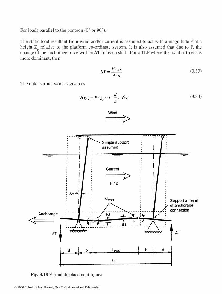
For loads parallel to the pontoon (0° or 90°):
The static load resultant from wind and/or current is assumed to act with a magnitude P at aheight Z
p relative to the platform co-ordinate system. It is also assumed that due to P, the
change of the anchorage force will be T for each shaft. For a TLP where the axial stiffness ismore dominant, then:
(3.33)
The outer virtual work is given as:
(3.34)
Fig. 3.18 Virtual displacement figure
© 2000 Edited by Ivar Holand, Ove T. Gudmestad and Erik Jersin

See also Fig. 3.18 for notations.
The relation between �� and � is given from the geometry of Fig. 3.18:
(3.35)
By comparing (5.10, 5.12 and 5.13), the bending moment at the boundary of the pontoon is:
(3.36)
The relation above is evolved for a static load parallel to the actual pontoon. For a differentload direction it is advantageous to use a simple frame program.
The moment diagram over the pontoon for the case shown in Fig. 3.18 would be linear withtension on the opposite side of the two pontoons and nil bending moment at the centre of thepontoon. The shear force from wind/current is constant along the pontoon.
By using the virtual work as mentioned above, it is vital to include all the loads contributingto the global equilibrium model, refer to contribution of T. (d) Residual sectional forcesEccentric positioning of the deck load during the mating operation generally leads to the needfor jacking operations to reduce the deformations and the sectional forces in the flexible raft;see Fig. 3.12. This and the simultaneous deballasting of the raft after mating leads topermanent stresses in the raft which must be accounted for in design.
The residual sectional forces can be calculated by hand or alternatively by using a beammodel in a computer. In this case, it is necessary to model the shaft/deck connection with afinite element model more accurately than is possible with hand calculations. A local shellelement model combined with a beam model of the lower part of the raft can be used. (e) Uneven ballastFig. 3.19 illustrates the situation with uneven ballasting for a doubly symmetrical raft. Twodiagonally opposite shafts have more ballast water whereas the two others havecorrespondingly less. The total ballast and the draft are therefore correct, but the internalredistribution introduces stresses in the raft.
By having the modal amplitude as the difference in the deflection between the two sets ofshafts, the stiffness of the model would be:
© 2000 Edited by Ivar Holand, Ove T. Gudmestad and Erik Jersin
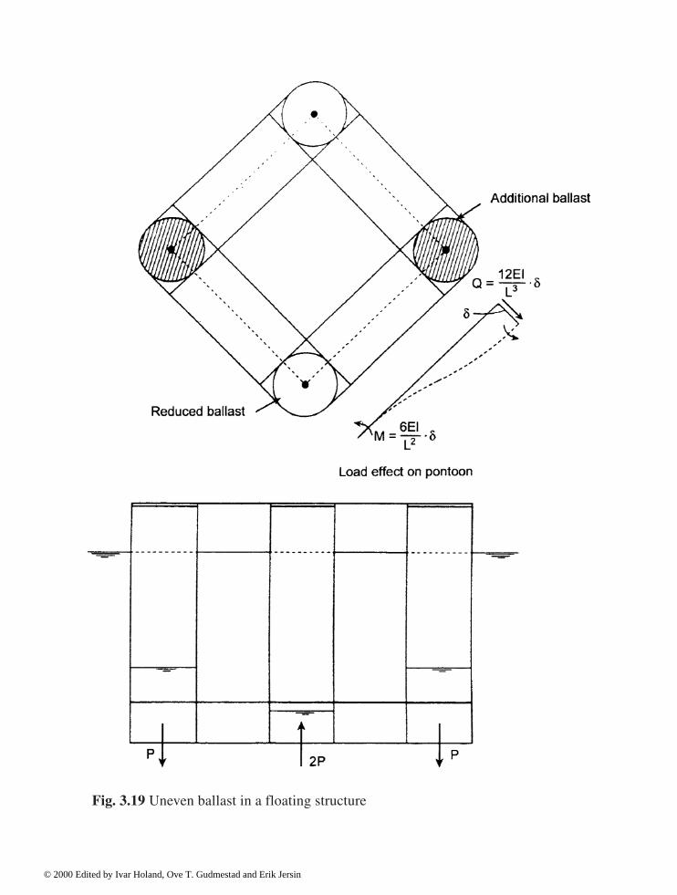
Fig. 3.19 Uneven ballast in a floating structure
© 2000 Edited by Ivar Holand, Ove T. Gudmestad and Erik Jersin
(3.37)
whereEI
PON= sectional stiffness about the horizontal axis of the pontoon
LPON
= effective length of the pontoon, distance between the boundaries.
For a catenary anchored structure, the raft will carry the entire uneven load. For a TLP on theother hand, a portion of the load will be carried by the tether axial stiffness. To find the relativedistribution between the tethers and the raft, a comparison is made between the raft modalstiffness in (3.37) and the modal stiffness of the tethers.
(3.38)
whereEA
TETH= sectional stiffness of tethers for each shaft
For a TLP, the raft will carry most of the uneven load since the modal stiffness in (3.37) is 10 to20 times larger than the contribution of the tethers (3.38).
The bending moment at the end of the pontoon is
(3.39)
where
P = the additional ballast per shaft.
From (3.39) the bending stresses in the pontoons can be calculated.
3.5.4 Global natural period
This section deals with the stiffnesses and masses for the deformation modes duringconstruction phases as well as the rigid body modes in the operation phases. The intention is todevelop a simple design method suitable for hand calculations to estimate the natural period. (a) Raft prior to deck matingAs mentioned in Section 3.5.2, the submerged phase just prior to deck mating is the mostcrucial with regard to the global response of the raft and also with regard to the largehydrostatic pressures exerted on the walls. By choosing the rotation of the shafts as modalamplitude, the modal stiffness contribution from two pontoons is obtained.
© 2000 Edited by Ivar Holand, Ove T. Gudmestad and Erik Jersin
(3.40)
For distribution of masses the following notations are used:
mCOL
= construction mass per unit height of column (shaft), ballast includedm
aCOL= additional mass from surrounding water per unit height of column
(shaft) = Cm x � g A
mPON
= construction mass per unit length of a pontoon, ballast includedm
aPON= additional mass from surrounding water per unit length of pontoon
= Cm x � g A.
With regard to the deformation mode in Fig. 3.12, the modal mass can be written
(3.41)
In (3.41) the lengths LCOL
, LWET
and LPON
are related to the centre axes.
An estimate of the natural period for the chosen mode is:
(3.42)
Among the effects mentioned above, the additional mass in the shafts will contribute most tothe modal mass.
In the submerged phase, Equation (3.42) can give a natural period in excess of 3 seconds. Toevaluate the load effect in this phase, the natural period must be compared with the sea state atthe actual location in protected water. In the Norwegian fjords waves giving natural periodsfrom 2 to 6 seconds can be expected. Damping is also low in the 3 second area and one cantherefore expect a substantial dynamic increase in the submerged phase prior to mating. (b) Platform in operationA catenary anchored structure is different from a tension leg platform particularly concerningheave and roll. For these motions, the TLP is much stiffer and therefore has lower naturalperiods. Typical natural periods for a TLP are:
© 2000 Edited by Ivar Holand, Ove T. Gudmestad and Erik Jersin

Horizontally : 60 to 120 secondsVertically : 2.0 to 4.0 seconds
The horizontal natural periods are determined from the lateral stiffness of the anchorage lines,while the water surface area and the axial stiffness of the lines contribute to the verticalstiffness. For a TLP the axial contribution is more dominant; see Section 3.5.3.
For rotational modes the illustration in Fig. 3.20 is used. Since the lateral anchorage forcesare small, the centre of rotation in the vertical direction will be dependent on the inertia forces.The actual masses are added in the figure. A centre of rotation is chosen with a verticalordinate Zo. The position of the centre of rotation Zo is chosen such that the horizontal resultantof the mass forces is zero. After that, the mass inertia moment, or the modal mass, isdetermined.
Fig. 3.20 Inertia forces due to roll
© 2000 Edited by Ivar Holand, Ove T. Gudmestad and Erik Jersin

3.5.5 First order wave
This section shows the use of deterministic wave theory to give an indication of the sectionalforces in the raft from the first order wave. (a) LoadsThe relation between maximum wave height and period for the actual field location is assumedto be supplied for ULS (100 year return period) and for SLS (1 year). Fig. 3.21 illustrates sucha relation.
Fig. 3.21 Wave height versus period
© 2000 Edited by Ivar Holand, Ove T. Gudmestad and Erik Jersin
Morison’s formula gives two contributions to the load on the raft. The viscous part given as:
(3.43)
where
� = specific gravity of seawater (1.027 t/m3)C
D= viscosity coefficient
vr
= relative velocity between wave particles and raftA = area across the velocity, per linear metre.
The other contribution in Morison’s formula is the mass component
FM = (1 + C
m) · � · V · w (3.44)
where
Cm
= coefficient for added massV = submerged volume per linear metrew = wave particle acceleration.
As is shown below, the mass component (3.44) is generally the most dominant. From (3.43)and (3.44) we notice that the contribution is 90° out of phase.
Distributed load at the waterline per metre length of a single shaft from the mass componentin Morison’s formula is then:
(3.45)
where
D = outer shaft diameterT = wave periodH = maximum wave height from Fig. 3.21.
The variation of load intensity as a function of water depth z from the waterline is
FM (Z)= F
MO · e-kz (3.46)
where
k = wave numberg = gravity acceleration
The total wave force on a shaft over a depth d would then be:
© 2000 Edited by Ivar Holand, Ove T. Gudmestad and Erik Jersin

(3.47)
(3.48)
Resultant at depth do below sea water level is
(3.49)
For short waves, approximate values are used
(3.50)
(3.51) Equations (3.48) to (3.51) are used later in the global equilibrium consideration.
For the evaluation of critical wave periods, it is interesting to look at the load resultant P as afunction of the wave period. The relation H/T in Fig. 3.21 is applied in (3.45) together with theactual outer diameter, specific density of water, as well as a factor for added mass. Since themass contribution is the most dominant and is 90° out of phase with the viscous term, only(3.45) and (3.50) are applied. (b) Waves in 0 and 90 degree directionsWaves in 0 and 90 degree directions act along the main axes of the platform; that is; parallel toor normal to the pontoons. For the bending moment in the pontoon close to the column aboutthe horizontal axis, the case illustrated in Fig. 3.22 often governs the design, with a wavelength between the shafts. The situation in Fig. 3.22 is also often critical for the shear at thepontoon ends. All four shafts now have their maximum horizontal wave load in one direction atthe same instant, implying horizontal acceleration of the platform
Fig. 3.18 is used together with the formulas in (3.3.2–3.3.6) in order to calculate the bendingmoment in the pontoon. The difference from the static expressions is now that the horizontalinertia force resultant is included, as indicated in Fig. 3.22. As horizontal motion is inertiadominated, for a catenary anchored platform as well as for a TLP, Equation (3.36) for staticload effect can be used directly, modifying the vertical arm z to be the distance between waveresultant load and the inertia force, added mass included. P is the resulting wave load on to theraft.
© 2000 Edited by Ivar Holand, Ove T. Gudmestad and Erik Jersin

Letting L (m) be the centre spacing of the shafts, the wave period T(s) representing theabove situation comes out as:
T=0.80 · L0.5 (3.52) In most cases the wave (3.52) is the shortest design wave for the structure. (c) Diagonal waveFor a bending moment in a pontoon about a vertical axis, a diagonal wave is often dominent. Inthe case of a quadratic floater with L (m) being the centre shaft spacing, the critical wavelengthcomes out as twice the diagonal spacing, with wave period:
T=1.35· L0.5 (3.53) Fig. 3.23 illustrates the mode of deformation resulting in a bending of the pontoons about thehorizontal and vertical axes, as well as torsion in the pontoons. Given the modal deformationpattern in Fig. 3.23 the modal contributions to stiffness from bending and torsion can becalculated. In most cases bending of the pontoons about the vertical axis gives by far thedominant terms.
Based on the deformation pattern in Fig. 3.23 the bending and torsion moments in thepontoons are calculated after the deformation amplitude has been found from the stiffnessexpressions. The load situation in Fig. 3.23 for the wave phases of 0 and 180 degrees creates noresulting horizontal load on the structure, and inertia forces do not enter into the expressions.Other wave phases are also to be considered, where platform rigid body motion is to beincluded.
© 2000 Edited by Ivar Holand, Ove T. Gudmestad and Erik Jersin
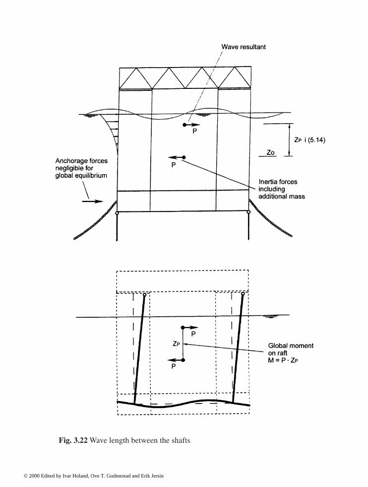
Fig. 3.22 Wave length between the shafts
© 2000 Edited by Ivar Holand, Ove T. Gudmestad and Erik Jersin

Fig. 3.23 Diagonal wave situation
© 2000 Edited by Ivar Holand, Ove T. Gudmestad and Erik Jersin

3.6 Ship impact
3.6.1 General
The present section outlines simplified calculation schemes for the response due to shipimpact. Major effort has been placed on techniques for calculating global responses, dynamiceffects included.
The objective of presenting the simplified impact considerations below, is among otherthings enabling estimates of section forces from impact to be made, and by comparing these toother load effects, evaluate whether ship impact is the governing force. Impact analysis is notpart of the automised design scheme and thus requires special analyses.
As a supplement to the global response, a complete analysis of impact also includespunching control. Here, the distributed load intensity from impact is the governing parameter,rather than the resultant load. Thus, hard impacts from smaller ships are often critical forpunching.
Methods for impact analysis of floating and gravity base structures are given below. Theillustrations are made for floating structures, so as to see the variation in dynamic effects fordifferent modes of motion, Gravity base structures follow the techniques in Section 3.6.5 forrotation, where the eigenperiod is in the range of the duration of impact.
3.6.2 Impact load
As shown in Fig. 3.24 a central impact is assumed, so that the impact force is directed throughthe vertical line in the platform mass centre, added mass from water included. The velocity ofthe ship prior to impact is denoted vo, mass of ship with added mass included is Ms, andplatform mass with surrounding water is Mp.
Further, it is assumed that the impact force is constant during the duration of the impact, andgiven by the plastic capacity of the ship. This is an approximation, since for plasticdeformation of the ship hull the contact force varies with the indentation. In subsequentexpressions the impact force is denoted P (kN) and the duration of impact t (s).
3.6.3 Impact mechanics
In Fig. 3.25 a diagonal impact is suggested towards one of the platform shafts. The loadresultant P acts in the waterline area. The global reference system lies at the elevation of theanchorages, with the X-axis directed along the impact force. The impact force has elevation habove the origin of co-ordinates.
© 2000 Edited by Ivar Holand, Ove T. Gudmestad and Erik Jersin
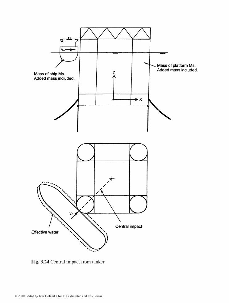
Fig. 3.24 Central impact from tanker
© 2000 Edited by Ivar Holand, Ove T. Gudmestad and Erik Jersin

The two-parameter system for analysis now has X as horizontal translation and R for rotationabout the global Y-axis. The following notation is used for stiffness and mass elements:
KXX = anchoring stiffness in translationKRR = rotation stiffness about origo due to anchoring and waterline areaMXX = translation mass from platform and added massMRR = rotation mass about origo of platform and added massMXR = mass coupling since the mass centre lies outside origo.
With the origo in the elevation where the anchorage system enters the structure, no couplingterms enter the stiffness, and the following 2x2 relation comes out of the impact mechanics(damping neglected).
Fig. 3.25 Diagonal central impact
© 2000 Edited by Ivar Holand, Ove T. Gudmestad and Erik Jersin

Platform:
(3.54)
Ship:
MS · X = -P (3.55)
Below, Equations (3.54) and (3.55) are implemented in modes of response with differentdynamic characteristics. The objective of the calculations is now to determine accelerationsand inertia forces due to impact, so that sectional forces can be found.
3.6.4 Catenary anchored floater
For a floater, the motions in the horizontal plane in the form of X-translation (surge) androtation about vertical axis Z (yaw) are inertia dominated, so that according to (3.2) thestiffness terms are neglected. It is now convenient to refer the displacements to the centre ofmass for the system, added mass included. Fig. 3.25 depicts the symbols for translation androtation directions of motion. For a catenary anchored floater the motion in roll or pitch is alsoinertia dominated. Equation (3.55) for the platform motion now becomes uncoupled also interms of mass:
Translation: MP · ü = P , (0 � t � t
1) (3.56)
Rotation: IMP
· � = P · d , (0 � t � t1) (3.57)
where
MP
= translation mass of the platform, added mass includedI
MP= inertia moment of the platform, added mass included
d = distance from mass centre to impact force resultantt = timet1
= impact duration.
The ship and platform common velocity during impact is thereby:
(3.58)
© 2000 Edited by Ivar Holand, Ove T. Gudmestad and Erik Jersin

(3.59)
(3.60)
From (3.58–3.60) the duration of impact can be calculated as the time when ship and platformhave the common velocity
vs = u. + d · �
. , (t = t
1) (3.61)
Impact duration:
(3.62)
The duration of impact t1 will normally be in the range 0.5–2.0 seconds.An estimate of the platform indentation in the ship hull is now obtained from the
displacements:
(3.63)
(3.64)
The assumption of constant impact force with time, causes (3.64) to underestimate theindentation if maximum force P is being used.
Fig 3.26 shows typical time functions for displacement u before and after impact. Themaximum displacement umax is obtained at time T/4 from contact, where T is the eigenperiod.The calculations for t > t1 apply the homogeneous equation corresponding to (3.54), includingthe initial conditions at t = t1. Ship and platform are to be considered as one mass.
© 2000 Edited by Ivar Holand, Ove T. Gudmestad and Erik Jersin
Regarding sectional forces in the raft, the situation during impact is governed by 0 � t � t1.The global structure behaviour is in the form of frame response effects in the raft. This is easilycalculated by hand as in Section 3.5.3, where impact force and inertia forces are included.Alternatively, a frame program is used.
3.6.5 Tension leg platform
For a TLP the eigenperiod in rotation about the horizontal axis is in the range 2.0–4.0 s, andstiffness and mass determine response in this mode. Dynamic amplification of the response, asrelated to static stiffness dominated reactions, can take place. The horizontal displacement insurge u is inertia dominated, also for a TLP.
From the above, the tension by platform produces different dynamic characteristics forimpact in the two modes of motion. As for the catenary anchored floater the stiffness KXX in(6.1) is neglected, and only inertia terms apply.
Referring to the mass centre, the parameters u and � in coupling terms in stiffness areneglected. Referred to the mass centre, added mass included, the two dynamic equations read
Translation : MP · ü=P (3.65)
Rotation : K
· +IMP
· =P · d (3.66)
Equations (3.65) and (3.66) now substitute (3.56) and (3.57) for a catenary anchored floater.The equation of motion (3.55) for the ship is still valid. Implementing the initial conditions:
= 0 for t = 0 (3.67)
=0 for t=0 (3.68)
Equation (3.66) is solved
(3.69)
with K
being the rotation stiffness, dominated by the tethers.
© 2000 Edited by Ivar Holand, Ove T. Gudmestad and Erik Jersin

Fig. 3.26 Time history for inertia dominated displacement
© 2000 Edited by Ivar Holand, Ove T. Gudmestad and Erik Jersin

Referring to Fig. 3.15, the rotation stiffness reads:
(3.70)
where EAi /L
i is axial stiffness of a single tether. The second contribution to K
comes from
the waterline area:
(3.71)
In (3.71) four shafts are assumed with distance c from the platform centre. Again, (3.71) can beneglected in practical design. Equation (3.69) includes the eigenfrequency � (rad per sec.) forrotation. As related to static solution, (3.69) comes out with a dynamic amplification:
DAF=(1 - cos �t) (3.72)
The extreme value of (3.72) is
(3.73)
where T is the eigenperiod. A dynamic amplification of 2.0 for the rotation mode seemsreasonable.
The estimation of impact duration t1 follows the procedure (3.58)—(3.62). Forsimplification, rotation terms may be neglected for the TLP.
Fig. 3.27 illustrates a typical time history for rotation in the case of impact duration t1
equal to half the eigenperiod T.For global response in the raft, the instant t = 0, t = t1
- and t = t1+ are to be controlled, where
t1- is the time just before the end of impact, and t1
+ is correspondingly just after the impact. Thereaction forces in the tethers give major contributions to retardation as soon as the impact forcedisappears.
The time history in Fig. 3.27 is also typical for the response in the shafts of a gravity baseplatform.
© 2000 Edited by Ivar Holand, Ove T. Gudmestad and Erik Jersin

Fig. 3.27 Time history for roll of TLP
© 2000 Edited by Ivar Holand, Ove T. Gudmestad and Erik Jersin
3.7 Non-linear geometric effects
3.7.1 General
This section deals with the incremental forces as a consequence of second order geometriceffects. In Section 3.7.2 the basis for the second order bending moment on beams is described.The objective is to illustrate simplified rules for calculating additional moments in rules andstandards (in e.g. (Eurocode 2, 1991), Section 4.3.5; (ACI 318–95, 1995), Sections 10.11–10.13; (NS 3473, 1998), Section A.12.2).
The formulas in Section 3.7.2 deal with the reduction of global stiffness of the shafts of agravity base structure and the increase of the sectional forces due to increased deformations.Section 3.7.3 similarly shows the effect on vertical panels, and how the equivalent one-dimensional elastic buckling length can be calculated for such a two-dimensional structuralelement. In Section 3.7.4, circular cylindrical shells are reviewed. Finally, Section 3.7.5 showsadditional forces on the raft due to large rigid body rotations.
3.7.2 Beam stiffness of shaft
The axial compression on the shaft reduces the bending stiffness and consequently the lateraldeformation increases. This is illustrated by an example below.
With reference to Fig. 3.6, a free rotation is assumed at the coupling between the shaft andthe deck. The deformation function along the shaft can be assumed:
w(x) = � · �(x) (3.74) where � is the displacement at the top of the shaft and �(x) is the deformation function.
The modal material stiffness which includes the sectional elastic stiffness EI, is given as
(3.75)
�fxx
is the curvature of the shape function.The stiffness reduction from the axial compression N in the shaft is given by the geometric
modal stiffness
(3.76)
where �,x is the slope of the shape function.
The criterion for linear buckling is now for the one-parameter system
KM - K
G = 0 (3.77)
i.e. the ideal elastic buckling load
© 2000 Edited by Ivar Holand, Ove T. Gudmestad and Erik Jersin
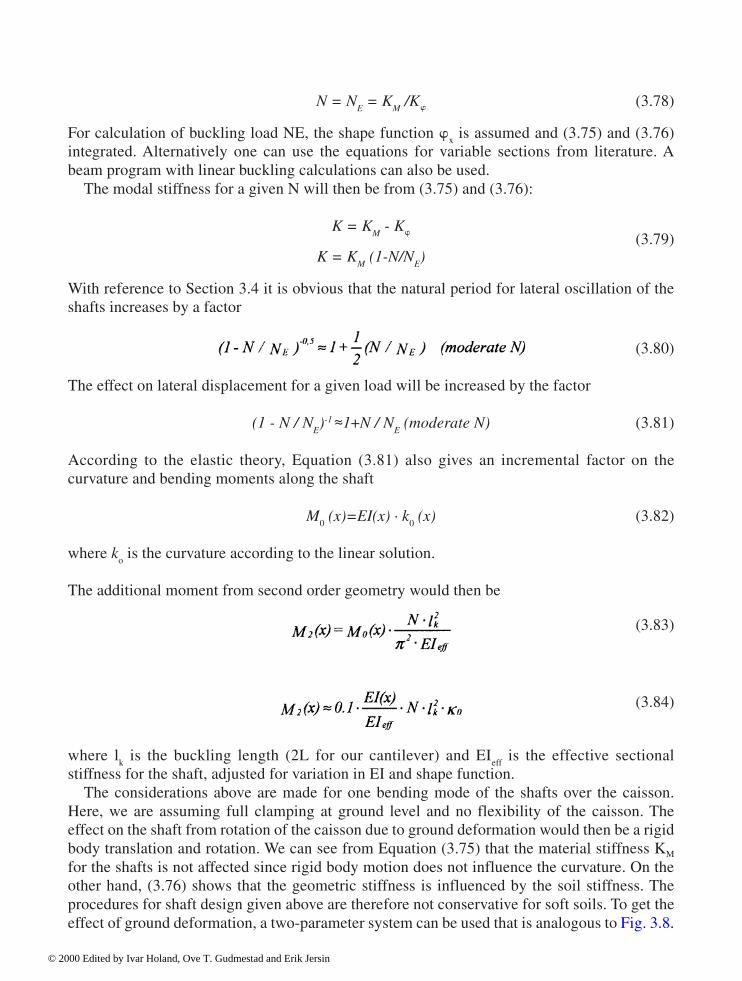
N = NE = K
M /K� (3.78)
For calculation of buckling load NE, the shape function �
x is assumed and (3.75) and (3.76)
integrated. Alternatively one can use the equations for variable sections from literature. Abeam program with linear buckling calculations can also be used.
The modal stiffness for a given N will then be from (3.75) and (3.76):
K = KM - K�
K = KM (1-N/N
E)
(3.79)
With reference to Section 3.4 it is obvious that the natural period for lateral oscillation of theshafts increases by a factor
(3.80)
The effect on lateral displacement for a given load will be increased by the factor
(1 - N / NE)-1 ~~1+N / N
E (moderate N) (3.81)
According to the elastic theory, Equation (3.81) also gives an incremental factor on thecurvature and bending moments along the shaft
M0 (x)=EI(x) · k
0 (x) (3.82)
where k
o is the curvature according to the linear solution.
The additional moment from second order geometry would then be
(3.83)
(3.84)
where l
k is the buckling length (2L for our cantilever) and EI
eff is the effective sectional
stiffness for the shaft, adjusted for variation in EI and shape function.The considerations above are made for one bending mode of the shafts over the caisson.
Here, we are assuming full clamping at ground level and no flexibility of the caisson. Theeffect on the shaft from rotation of the caisson due to ground deformation would then be a rigidbody translation and rotation. We can see from Equation (3.75) that the material stiffness KM
for the shafts is not affected since rigid body motion does not influence the curvature. On theother hand, (3.76) shows that the geometric stiffness is influenced by the soil stiffness. Theprocedures for shaft design given above are therefore not conservative for soft soils. To get theeffect of ground deformation, a two-parameter system can be used that is analogous to Fig. 3.8.
© 2000 Edited by Ivar Holand, Ove T. Gudmestad and Erik Jersin
3.7.3 Planar structural elements
The plane stresses �x, �y, �xy are transformed to principal stresses �1 and �2. Here �2 is thelargest compressive stress. The stress �1 will be considered below only if it is compressive.
From the geometry and boundary conditions of a planar structural element, the criticalbuckling stress �2 cr is calculated with regard to the combined stress state �1/�2. Tables for idealplate buckling from (Timoshenko and Gere, 1961) or (Column Research Committee of Japan,1971) can be used. Another alternative procedure is: a. Deal with each principal stress separately. Calculate the buckling stresses
(3.85)
(3.86) where b is the effective plate width which can be different for �
1 and �
2, t the plate thickness,
and D the sectional stiffness. b. Find the relation � between the acting principal stresses, such that
�1=� · �
2(� > 0) (3.87)
c. Critical principal stress �2cr
from the combined effect can be derived from the interactionformula
(3.88)
d. When the critical stress is found, the equivalent one-dimensional buckling length can be derived from:
(3.89) i.e.
(3.90)
Buckling length lk2
from (3.90) is used in conjunction with the acting stress �2 for slenderness
control according to Section 12.2.4 in the Norwegian Standard and to calculate the incremental
© 2000 Edited by Ivar Holand, Ove T. Gudmestad and Erik Jersin

moment according to (3.74) above. The two principal directions are to be considered for theincremental moment.
3.7.4 Circular cylindrical shell
The same procedure mentioned above in Section 3.7.3 is used to find the second ordersectional forces. The only difference is the elastic buckling stresses.
Provided the membrane compressive stress �1 is in the hoop direction and �2 in thegeneratrix direction and that the membrane shear is negligible for second order effects, thenthe ideal buckling stress for �1 acting alone can be written (Timoshenko and Gere, 1961), or(Column Research Committee of Japan, 1971).
(3.91)
where
E = modulus of elasticity of concretev = Poisson’s ratiot = wall thicknessr = middle radiusl = effective length.
With �2 acting alone, the elastic buckling stress can be written (Timoshenko and Gere, 1961)
or (Column Research Committee of Japan, 1971).
(3.92) provided that
l»1.72 · (rt)0.5 (3.93) With the help of interaction formulas as in (3.87) and (3.88) above, the critical stress can becalculated. It is convenient to use the hoop stress �
1 as a reference rather then �
2 as in (3.87)
and (3.88), after which lk1
is calculated from (3.89) and (3.90). By setting lk1
in relation to thecylinder circumference, an estimate of the number of half waves in the buckling mode aroundthe periphery is obtained. This is an important check particularly for cases where the circularcylinders do not form a full circle (similar to the cell walls of gravity base platforms). Thevalidity of (3.91) for a partly complete cylinder can then be confirmed.
For slenderness control and for calculations of the second order moment, the procedure inSection 3.7.2 is followed. As a reminder the second order moments are to be calculated forboth directions. Often the governing case is during the mating of the deck to the shaft.
For the lower part of a shaft of a floating platform or the cell walls of a gravity basestructure, the stresses are derived from the water pressure p:
© 2000 Edited by Ivar Holand, Ove T. Gudmestad and Erik Jersin

(3.94)
(3.95)
In other words, the vertical stress is half the hoop stress.
Practical values can be:
Wall thickness t = 0.60mMiddle radius r = 12.0mCylinder height 1 = 30.0mModulus of elasticity E = 30 000 MPaPoisson’s ratio v = 0.20
From (3.91) the critical buckling stress for the hoop force alone
�1E
= 112MPa ,(�2 = 0) (3.96)
and for vertical stress alone from (3.92)
�2E
= 884 MPa , (�1 = 0) (3.97)
From the stress relationship in (3.94) and (3.95) and the buckling stresses in (3.96) and (3.97) it isclear that, generally speaking, the hoop stress is more dominant with regard to second order effects.
3.7.5 Rigid body rotation of a floating structure
The computational models for the global effects on the raft, shown in Section 3.5 and Fig.3.17, are geometrically linear as the rigid body modes are not included, and the deformationmodes are assumed to give infinitesimal displacements. Note that displacements include bothtranslation and rotation.
This last assumption about the minor displacements from the deformation modes is valid formost of the floating platforms. At the same time, the rigid body rotation in a catenary anchoragesituation can be so large that additional forces are exerted on the raft. An uncontrolled accidentalwater ballasting situation can result in a rigid body rotation (or tilt) of several degrees.
As shown in Fig. 3.28 such a rotation will lead to a lateral load on the raft due to the weightand also an increase in the hydrostatic pressure due to the deeper draft. The lateral force fromthe weight corresponds to the inertia force from acceleration in translation such as:
© 2000 Edited by Ivar Holand, Ove T. Gudmestad and Erik Jersin

X = - g · sin (3.98) The change in water pressure is
p=p g · X · sin (3.99) For purposes of comparison, a wave acceleration for a 100 year storm of about 1.0 to 1.5 m/s2,leads to the same lateral force on the raft as a rotation of the raft of �=6.00. The tilted position,shown in Fig.3.28, can also be critical for the connection between the raft and the deck.
Further reading
The following references are recommended as a supplement to the present Chapter 3:
R.W.Clough and J.Penzien (1975): ''Dynamics of Structures'', McGraw-Hill.
Fig. 3.28 Lateral forces from rigid body rotation
© 2000 Edited by Ivar Holand, Ove T. Gudmestad and Erik Jersin

S.P.Timoshenko and W.Krieger (1959): ''Theory of Plates and Shells'', McGraw-Hill.
S.P.Timoshenko and J.M.Gere (1961): ''Theory of Elastic Stability'', McGraw-Hill.
Column Research Committee of Japan (1971): ''Handbook of Structural Stability'', CoronaPublishing Company; Tokyo.
T.Sarpkaya and M.Isaacson (1981): ''Mechanics of Wave Forces on Offshore Structures'', vanNostrand Reinhold Company.
T.H.Søreide (1981): ''Ultimate Load Analysis of Marine Structures'', Tapir, Norway.
References
American Concrete Institute (1995) Building Code Requirements for Structural Concrete (ACI318–95) and Commentary—ACI 318R 95 (metric versions ACI 318M-95 and ACI 318RM95)
Eurocode 2 European Prestandard ENV 1992–1–1. (1991): Design of concrete structures.CEN 1991 (under revision 1999 for transformation to EN, European Standard).
Norwegian Council for Building Standardisation, NBR (1998), Concrete Structures, Designrules. NS 3473, 4th edition, Oslo, Norway, 1992 (in English), 5th edition 1998 (Englishedition in print).
© 2000 Edited by Ivar Holand, Ove T. Gudmestad and Erik Jersin
4 Global analyses
Ivar Holand, SINTEF
4.1 Objective
The analyses of offshore structures may be split in several steps: • load analyses• modelling, preprocessing• global analysis• study of selected areas by non-linear analyses• postprocessing, dimensioning, including analysis of reinforcement needed. In this chapter only the global analysis will be discussed. The other steps are, to some extent,discussed in Chapters 3 and 5.
The objective of the global analysis is to provide an accurate and detailed knowledge of thedesign load effects as they are distributed all over the structure. The load cases to be includedin the linear global analyses must be chosen in such a manner as to allow all relevant loadcombinations to be achieved by linear combinations.
Global analyses of offshore structures are carried out exclusively by linear analyses. Thereare several reasons for using linear elastic analyses in accordance with the theory of elasticity,among which should be mentioned: • The structures, in particular the caissons made up of circular cells, are complex, and the
main stress distribution is not obvious.• The offshore platforms are subjected to a large number of loading conditions during the
construction, tow-out, installation, operation and removal phases. Large hydrostaticpressures dominate during deck-mating, while wave, current and wind loads dominateduring the operation phase. To permit the handling of all relevant load cases, a number ofbasic load cases are selected. The actual load cases, with load factors for the relevant limitstate, possible amplification factors etc, may in a linear analysis be obtained by linearscaling and superposition, allowing an automatic postprocessing.
• The solution found satisfies equilibrium and provides a reasonable distribution of staticallyindeterminate forces.
• The linear solution gives an adequate basis for design for serviceability.• The simultaneous occurrence and the relative magnitude of several section forces may be
important, e.g. the sign and magnitude of a normal force acting together with a shear force.
It is assumed that non-linear analyses will gain importance, since they provide reasonablecorrespondence between assumed material behaviour in an ultimate limit state design, and the
© 2000 Edited by Ivar Holand, Ove T. Gudmestad and Erik Jersin

100 Global analyses
distribution of internal section forces in the structure. They also enable the influence ofdisplacements on load effects to be considered. However, when the large number of load casesand the resulting need to superimpose load effects are considered, the linear analysis is likelyto remain the primary method in a foreseeable future.
Here, a global linear analysis will primarily be discussed, but non-linear analyses will alsobe touched upon. Dimensioning is discussed in Chapter 5 (Design). In non-linear analysesdimensioning cannot, however, always be separated from analysis.
4.2 Linear finite element methods
4.2.1 Description of methods
The structural analyses have, since the mid-seventies, mainly been based on the use of largefinite element programs. Description of finite element methods are found in a number oftextbooks, e.g. (Bathe, 1982), (Cook et al., 1989), (Zienkiewicz and Taylor, 1989), (NAFEMS,1991), (Crisfield, 1991), (Saabye Ottoson and Petersson, 1992), (Hinton, 1992).
The finite elements may be categorized as: • bar elements• beam elements• plane stress elements• plate bending elements• shell elements• solid elements• several kinds of special elements. Whereas bar and beam elements describe the loadbearing at the same level of accuracy (orwith greater accuracy) as when using the traditional strength of materials, the moresophisticated elements may be developed in several ways and with different levels of accuracy.Various versions of these elements are described in the textbooks mentioned above.
The choice of elements and models govern the accuracy. Hence, the person using a program mustevaluate what accuracy can be achieved with the element type used. Accuracy here means accuracycompared with the linear theory of elasticity. Exact solutions according to the theory of elasticity maybe obtained only in certain idealized cases. The power of the finite element method is that it providesa systematic approach and, correctly applied, a good approximation to the theory of elasticity.
Solid elements in the shape of regular or irregular hexahedrons with 8 nodes (one in eachcorner) have been frequently applied. If such elements are used, it must be recognized thatirregular elements may cause considerable errors, and that the accuracy obtained by regularelements depends on the displacement functions and the integration approach applied (severalvariants of this element exist). In the same manner, irregular quadrilateral elements with 4nodes for plane stress or plane strain should be used with care.
Solid elements with 20 nodes are more robust concerning the element shape, and generallygive better results. This is even more the case for solid elements with 27 nodes; see Section 8.7in (Zienkiewicz and Taylor, 1989).
In present usage in offshore structures solid elements are preferred, not because detailed© 2000 Edited by Ivar Holand, Ove T. Gudmestad and Erik Jersin

Global analyses 101
linear stresses are needed, but because the modelling of a complex geometry and theapplication of water pressure on external surfaces is facilitated using solid elements. Sub-structuring is used to make the modelling more modular. The responses are stored in thedatabase as stresses in the super-convergent (Barlow) points.
The largest finite element calculations may involve more than one million degrees ofdisplacement freedoms and requires the use of super-computers (CRAY YMP/464 has beenused for the largest analyses) (Brekke, Åldstedt and Grosch, 1994).
In design, stresses and stress resultants are also needed at the boundary of the structural part,normally at the interface with an other structural part, and these values must be found byextrapolation from the internal points. The accuracy of this extrapolation (linear, parabolic)must be assessed, and when using the results it should be observed how the actual type ofquantity would vary close to an edge. An example of an unfortunate effect of extrapolation isshown in connection with Fig. 4.8.
Irrespective of the choice of element type, the user should thoroughly study the informationon the choice of element type and the modelling of the element mesh to understand thelimitations of the program system (see examples in Section 4.2.5).
If the program manuals or previous applications of the same program do not providesufficient documentation for an evaluation of accuracy, users must use test examples to providesufficient insight in the obtainable accuracy.
A way of testing accuracy is to use the element chosen for a simple, but thoroughrepresentative, static model with a known analytic solution. For example, a clamped beam, asimply supported quadratic plate, an axial-symmetric tank or a spherical shell with simpleboundary conditions. Examples are shown in Section 4.2.5. Accuracy assessments and testanalyses must be included in the documentation.
The results in areas with irregular elements should always be scrutinized. If elements insuch areas are generated automatically, the mesh must be studied and adjusted as necessary.
In some places irregular elements cannot be avoided, for instance in a transition zonebetween small and larger elements, or in cases of irregular geometry, for example at theinterface between cell elements or in domes. It is important that irregular elements are placedin areas where the stresses are of secondary interest, or in areas with small stress gradients.Stresses in irregular elements should be used with care in design. Such cases should be subjectto special assessment, by comparison with earlier accuracy studies of similar cases, or byanalysing simple cases by the same element model for the local area.
Re-entrant corners give singular points and thus theoretically infinite stresses in an analysisaccording to the linear theory of elasticity. At such points the calculated stresses may get any value,depending on the element model. The case is not critical, since stress resultants, which are used inthe design, are finite. However, by studies of accuracy it is necessary to be aware of the phenomenon.
Tools to support the study of the accuracy of finite element models are so far only implementedin commercial software to a limited extent. A check described in textbooks referred to above isthe “patch test”. If the test is satisfied, the solution converges to the correct result when theelement size approaches zero. The test, however, says nothing about the accuracy for a certainelement size and shape. Accuracy of stress resultants, not local stresses, is vital in design ofconcrete structures (Mathisen, Kvamsdal and Okstad, 1994), (Kvamsdal and Mathisen 1994).
When it is deemed necessary to account for the non-linear behaviour of reinforced concrete,particularly because of cracking, additional non-linear analyses are adapted for isolated parts,
© 2000 Edited by Ivar Holand, Ove T. Gudmestad and Erik Jersin

102 Global analyses
using results known from linear analyses at the boundaries. Such analyses are required inhighly stressed intersections between shell type structural members and for slender shellpanels, where geometrical non-linearities may also be important.
4.2.2 Program systems
A number of program systems are commercially available. It is necessary to choose a programsystem that has or gives access to relevant pre- and postprocessors, including load generationprocedures for the relevant types of loads. Postprocessing is discussed in Chapter 5, Section5.3.2, where also relevant postprocessors are listed.
4.2.3 Modelling and element meshes for shell surfaces
The isolated structural parts usually have simple geometries such as plane plates, circularcylinders, spherical domes and circular ring beams. By modelling for the use of a shellprogram, a reference surface in the middle of the thickness is chosen, resulting in amathematical model with surfaces which can easily be generated automatically. The procedurebecomes more complex if the thickness varies and a simple mathematical expression is chosenfor the concrete form side. The most correct reference surface for a static analysis is a middlesurface, and a deviation between the middle surface and a reference surface creates normalforces forming a narrow angle with the middle surface. Even though the angle is narrow, theeffect can be significant; since shear forces and shear strengths are small compared to normalforces. Hence, a correction is needed, either of the automatically generated nodal pointgeometry, or of the results, especially those related to shear forces, for deviations between thereference surface and the middle surface. If an element model with solid elements is chosen,the modelling may be simplified, but the physical problem returns when shear forces and axialforces are to be computed from the stresses; see Chapter 5 (Design).
The choice of element size depends on the element types and the gradients of the quantitieswhich are to be described; in the present case this means how the stress resultants in shell- andplate-shaped structural parts vary over the surfaces.
The structural parts are joined together in such a way that the bearing function is complexand the gradients are not accurately known until the analyses have been completed.Nevertheless, knowledge about gradients for simpler cases with known analytical solutionsprovides good support.
For a one-way slab with a uniform load the gradients only depend on the width spanned. Theelement size may thus be chosen in relation to the width (example: tri-cell walls in Condeep platforms).
For singly and doubly curved shell surfaces the loads may be considered to be carried bymembrane forces, with the qualification that the membrane state is disturbed by edges, which inour case are mainly horizontal or vertical. The edge disturbances materialize as bending momentsand shear forces in the shell. These edge disturbances are described mathematically as dampedsine and cosine functions and show large gradients. The element size close to the edge must bechosen in such a manner that the edge disturbances are sufficiently accurately described.
For a cylindrical tank with constant thickness and axial-symmetric loading, edge disturbances
© 2000 Edited by Ivar Holand, Ove T. Gudmestad and Erik Jersin

Global analyses 103
emerge from the horizontal edges (for a Condeep cell from the upper or lower domes, see alsoChapter 3 (Simplified analyses)). The damping of edge disturbances, and hence the variationwith the distance z from the edge is a function of the non-dimensional coordinate
z/√(rt) (r=radius, t=thickness) (The parameter √(rt) is related to the elastic length as applied in Chapter 3, by a constantfactor.) The variation is shown in Fig. 4.1 for a moment M and in Fig. 4.2 for a shear force Qacting at the edge.
To reduce uncertainties in the transition from analysis to design, it is also important tochoose an element model that is suited for the subsequent design. This aspect is discussedmore closely in Chapter 5.
As Figs 4.1 and 4.2 show, the edge disturbances are limited to a zone extending about 2z/√(rt) from the edge, and the large gradients are found within a distance of about √(rt) from theedge (see also Fig. 4.5).
For edge disturbances for a spherical shell, the damping is approximately as for a cylindricalshell, when the radius of the sphere replaces the radius of the cylinder.
For an edge along a generator in a cylindrical shell, the damping is slower, and the situationmore complex. The difference between a simple arch and an arch in a shell is mainly found in therestraining of tangential displacements of the arch in the shell, caused by the shell surface. Thedegree of restraining depends on the shell length measured along the generator, radius/thicknessratio, etc. The largest gradients occur for strong restraining. For our objective, namely an assessmentof the element size, it is conservative to assume completely rigid tangential restraining. In thatcase the differential equation for the arch will be the same as for the axial-symmetric tank; thedamping will be the same. Thus, the extension of the elements at a straight edge can be chosenequal to the extension of the elements in the direction of the generator at the curved edges.
4.2.4 Design brief
In order to have analysis approaches, organization, responsibility allocation and quality assurancethoroughly discussed and decided; a Design Brief should be worked out for the element analysis.The Design Brief should also describe error estimates. These documents may be separate or partsof a more general document. Design Briefs are discussed in more detail in Chapter 5.
4.2.5 Examples of accuracy studies
(a) Background for the examplesAs a part of the investigation work after the loss of the Sleipner A platform (Holand, 1994)Statoil contracted SINTEF to carry out a number of studies of accuracy. A selection ofexamples from these studies is included here. The good accuracy demonstrated for thecylindrical walls is assumed to represent a normal accuracy obtained by finite elementmethods. The errors for the tri-cell walls are, however, particularly large, and illustrate therisks that may be connected with the application of finite element programs, and the necessityof a careful application of program systems.
© 2000 Edited by Ivar Holand, Ove T. Gudmestad and Erik Jersin

104 Global analyses
Fig. 4.1 Variation with distance from edge, of a moment M, acting at a curved edge of acylindrical shell
Fig. 4.2 Variation with distance from edge, of a shear force Q, acting at a curved edgeof a cylindrical shell
© 2000 Edited by Ivar Holand, Ove T. Gudmestad and Erik Jersin

Global analyses 105
(b) Cylindrical shellFig. 4.3 shows a cylindrical wall constituting a part of an axial-symmetric cell with externalpressure. The wall is assumed to be clamped at the upper edge. By also clamping the loweredge, symmetry is obtained about a section at the middle of the height, as shown in Fig. 4.3.The model is reasonably close to the actual situation in an external cell in a Condeep platformand is assumed to be representative for a model case suited for an investigation of accuracy.
The shell has been modelled by solid elements, and an element model shown in Fig. 4.4.Each element has 8 nodes. Moments and shear forces computed by using the program systemNASTRAN are shown in Fig. 4.5.
With the simple assumptions a differential equation may also be used for the analysis of thecell. Such an analysis gives a clamping moment of 1.75 MN and a shear force at the edge of1.873 MN/m. The results from the element analysis (1.71 MN, respectively 1.849 MN/m,) arethus very close to the theoretically exact ones, and the model for the cylinder wall must beconsidered to be fully satisfactory.
Fig. 4.3 Cylindrical wall. Geometry and edge conditions
© 2000 Edited by Ivar Holand, Ove T. Gudmestad and Erik Jersin

106 Global analyses
Fig. 4.5 Moments [MNm/m] and shear forces [MN/m] in cylindrical wall
Fig. 4.4 Element model for cylindrical wall
© 2000 Edited by Ivar Holand, Ove T. Gudmestad and Erik Jersin

Global analyses 107
(c) Plane cell wallFig. 4.6 shows a section of an element model as it has been modelled by a pre-processor. Thesection has been placed around a tri-cell and includes the tri-cell walls and adjacent walls. (Amore complete description of a structure of this type is found in Chapter 3.) The accuracyobtained by this type of modelling will be investigated for the load case internal water pressurein the tri-cell. The problem is local and may be studied by analysing the local area included inthe plane element model in Fig. 4.6. The pre-processor has produced the element model bydividing the inside as well as the outside of the cell wall in equal element side lengths. Theprocedure may seem logical, but the skew elements cause problems.
An analysis using NASTRAN yields bending moments and shear forces in the cell wall asshown in Figs. 4.7 and 4.8. Computed values in the centres of gravity of the elements are usedas a basis and are extrapolated to the edge. The correct sum of moments in the middle of thespan and at the support is ql2/8, whereas the distribution between span and support depends onstiffness. As shown in Fig. 4.7 the analysis yields a moment sum, which is 15% too small.
The shear force varies linearly and is equal to ql/2 at the support. Here the result is still muchworse, since the element at the support gives too small a value, and even more since theextrapolation by a parabola through points A, B and C is unfortunate. Depending on what pointis considered, the shear force is 38 or 41% too small.
A change to regular elements as shown in Figs. 1.6 and 1.7 gives a moment sum as well as ashear force very close to the exact ones.
The conclusion is that the element in the NASTRAN version used involves the risk of largeerrors even for relatively moderate deviations from the rectangular shape, but also that suchdeviations may be revealed by simple investigations.
Much better stress resultants may be obtained by using a different interpretation of theresults from the element analysis (Mathisen, Kvamsdal and Okstad, 1994). It is shown in thereference that the same example, with the element model as shown in Fig. 4.6, but with aninterpretation of results based on virtual work, gives exact axial and shear forces and an errorof only 7% in the moment in the critical section.
4.3 From linear analysis to design
The stress resultants found by the linear analysis are correct only if the material is homogeneousand linearly elastic. However, they are in any case a good approximation, since they satisfyequilibrium and also to a reasonable extent the relations between strains and stresses. It should,however, be observed that only the nodal forces satisfy equilibrium completely. When the programcomputes strains from nodal displacements, and later stresses and stress resultants from the strains,and even extrapolates the results to the boundary, the procedure is not uniquely defined. Also,there is no guarantee that these stress resultants satisfy equilibrium. For a good element modelthe deviations are small, but nevertheless, these uncertainties contribute to the needs for accuracyinvestigations as discussed in Section 4.2; see also examples in Section 4.2.5
The further design process in the ultimate limit state is not based on the theory of elasticity,but on the assumption that concrete cannot take tensile stresses. The process also uses designprocedures that are analogous to those used in traditional concrete design; see Chapter 5. Evenif design is based on assumptions that are different from those used in the analysis, the stressresultants are not corrected for this difference.
© 2000 Edited by Ivar Holand, Ove T. Gudmestad and Erik Jersin

Fig. 4.6 Generated element model for tri-cell
© 2000 Edited by Ivar Holand, Ove T. Gudmestad and Erik Jersin
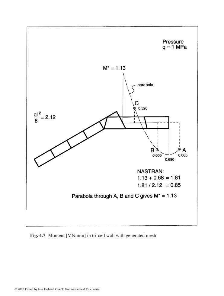
Fig. 4.7 Moment [MNm/m] in tri-cell wall with generated mesh
© 2000 Edited by Ivar Holand, Ove T. Gudmestad and Erik Jersin

Fig. 4.8 Shear force [MN/m] in tri-cell wall with generated mesh
© 2000 Edited by Ivar Holand, Ove T. Gudmestad and Erik Jersin

Fig. 4.9 Moment [MNm/m] in tri-cell wall with modified mesh
© 2000 Edited by Ivar Holand, Ove T. Gudmestad and Erik Jersin

Fig. 4.10 Shear force [MN/m] in tri-cell wall with modified mesh
© 2000 Edited by Ivar Holand, Ove T. Gudmestad and Erik Jersin

Global analyses 113
Normally the deviations caused by non-linear behaviour are small (in the case of staticallydeterminate structures even zero), and the procedure is feasible. Nevertheless, there are caseswhere non-linear analyses are needed, see Section 4.5. If in doubt, displacements due to non-linear behaviour should be estimated and resulting additional moments and forces assessed.
4.4 Postprocessing
When the linear analysis for all chosen basic load cases is completed, the results are stored ondata files for subsequent processing as described in Chapter 5. The transfer of data to thepostprocessor, which may even be found in a different organization and be used by manyothers, is a critical process. This implies that the transfer must be subjected to qualityassurance according to specified routines, which will prevent sources of error, such asincorrect files being used in the postprocessing. Moreover, the stress resultants from thepostprocessing must be checked against the relevant loads.
The postprocessor should, in addition to its primary objective to be a design tool, also beorganized as an efficient tool in checking that the results are correct. The postprocessor should,hence, include routines allowing diagrams to be drawn in a form which is suited to check thestructural response. The requirement implies that the routines should be especially adapted tothe needs of the design of reinforced concrete structures. The diagrams should include stressresultants in the relevant shell and plane sections (Mx, My, Mxy, Nx, Ny, Nxy, Qx, Qy) and stressresultant over larger portions, for example bending moments and shear forces in shafts(columns). Displacement diagrams are also valuable tools to understand the structuralbehaviour, and to check the results.
Generally, it may be said that assumptions inherent in the analysis model also are to befound as results in the output. A large amount of data is produced, and it is essential to sort outthe critical load cases and concentrate diagrams and discussion of results on these criticalcases. Such studies should be included in the documentation.
The part of the postprocessing that is directly related to the design of reinforced concrete isdiscussed in Chapter 5.
A main cause of concern about the linear finite element analysis is whether it produces adesign that is too expensive, especially if the resulting amounts of reinforcement are unnecessarilyhigh. The linear theory of elasticity often provides large local stress peaks in locations withirregular element geometry. The finer the element mesh, the more accurately local stress peaksare described by the finite element methods. Similarly, it may be questioned whether it is necessaryto design for large local section forces caused by elastic restraints. In traditional concrete designsuch stress concentrations have often been neglected or reduced by smoothing the peaks overlarger areas. Also for marine concrete structures it may be unnecessary to design for all stresspeaks. Procedures must be evaluated in the modelling, for instance by reducing stiffness, or indesign, by smoothing, which may be included in the postprocessor. It is difficult to give rules forthis, but reductions must be restricted to stresses that are unnecessary for equilibrium, andsmoothings made in such a manner that the total stress resultants satisfy equilibrium. They must,furthermore, be restricted to the ultimate limit states.
Such smoothings and reductions are obviously accepted in accidental situations, where localfailure is accepted provided that no total structural failure results.
© 2000 Edited by Ivar Holand, Ove T. Gudmestad and Erik Jersin
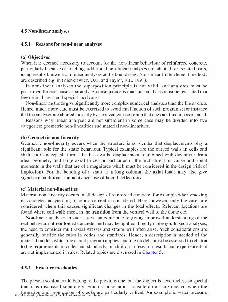
114 Global analyses
4.5 Non-linear analyses
4.5.1 Reasons for non-linear analyses
(a) ObjectivesWhen it is deemed necessary to account for the non-linear behaviour of reinforced concrete,particularly because of cracking, additional non-linear analyses are adapted for isolated parts,using results known from linear analyses at the boundaries. Non-linear finite element methodsare described e.g. in (Zienkiewicz, O.C. and Taylor, R.L. 1991).
In non-linear analyses the superposition principle is not valid, and analyses must beperformed for each case separately. A consequence is that such analyses must be restricted to afew critical areas and special load cases.
Non-linear methods give significantly more complex numerical analyses than the linear ones.Hence, much more care must be exercised to avoid malfunction of such programs; for instancethat the analyses are aborted too early by a convergence criterion that does not function as planned.
Reasons why linear analyses are not sufficient in some case may be divided into twocategories: geometric non-linearities and material non-linearities. (b) Geometric non-linearityGeometric non-linearity occurs when the structure is so slender that displacements play asignificant role for the static behaviour. Typical examples are the curved walls in cells andshafts in Condeep platforms. In these walls, displacements combined with deviations fromideal geometry and large axial forces in particular in the arch direction cause additionalmoments in the walls that are of a magnitude which must be considered in the design (risk ofimplosion). For the bending of a shaft as a long column, the axial loads may also givesignificant additional moments because of lateral deflections. (c) Material non-linearitiesMaterial non-linearity occurs in all design of reinforced concrete, for example when crackingof concrete and yielding of reinforcement is considered. Here, however, only the cases areconsidered where this causes significant changes in the load effects. Relevant locations arefound where cell walls meet, in the transition from the vertical wall to the dome etc.
Non-linear analyses in such cases can contribute to giving improved understanding of thereal behaviour of reinforced concrete, and may be applied directly in design. In such analyses,the need to consider multi-axial stresses and strains will often arise. Such considerations aregenerally outside the rules in codes and standards. Hence, a description is needed of thematerial models which the actual program applies, and the models must be assessed in relationto the requirements in codes and standards, in addition to research results and experience thatare not implemented in rules. Related topics are discussed in Chapter 5.
4.5.2 Fracture mechanics
The present section could belong to the previous one, but the subject is nevertheless so specialthat it is discussed separately. Fracture mechanics considerations are needed when theformation and progression of cracks are particularly critical. An example is water pressure
© 2000 Edited by Ivar Holand, Ove T. Gudmestad and Erik Jersin
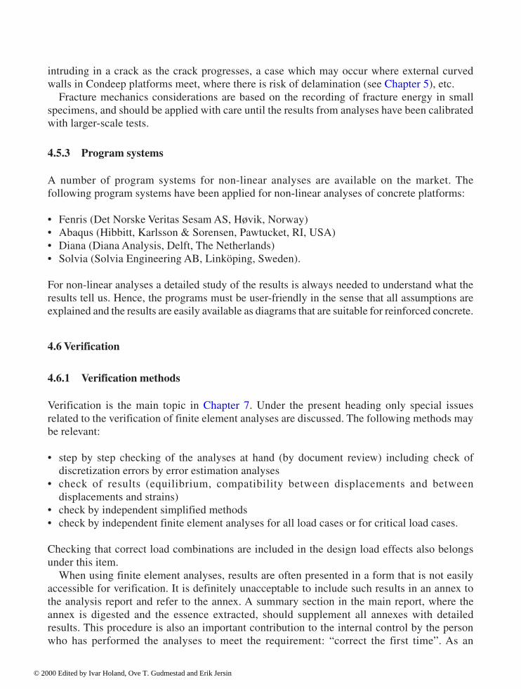
Global analyses 115
intruding in a crack as the crack progresses, a case which may occur where external curvedwalls in Condeep platforms meet, where there is risk of delamination (see Chapter 5), etc.
Fracture mechanics considerations are based on the recording of fracture energy in smallspecimens, and should be applied with care until the results from analyses have been calibratedwith larger-scale tests.
4.5.3 Program systems
A number of program systems for non-linear analyses are available on the market. Thefollowing program systems have been applied for non-linear analyses of concrete platforms: • Fenris (Det Norske Veritas Sesam AS, Høvik, Norway)• Abaqus (Hibbitt, Karlsson & Sorensen, Pawtucket, RI, USA)• Diana (Diana Analysis, Delft, The Netherlands)• Solvia (Solvia Engineering AB, Linköping, Sweden). For non-linear analyses a detailed study of the results is always needed to understand what theresults tell us. Hence, the programs must be user-friendly in the sense that all assumptions areexplained and the results are easily available as diagrams that are suitable for reinforced concrete.
4.6 Verification
4.6.1 Verification methods
Verification is the main topic in Chapter 7. Under the present heading only special issuesrelated to the verification of finite element analyses are discussed. The following methods maybe relevant: • step by step checking of the analyses at hand (by document review) including check of
discretization errors by error estimation analyses• check of results (equilibrium, compatibility between displacements and between
displacements and strains)• check by independent simplified methods• check by independent finite element analyses for all load cases or for critical load cases. Checking that correct load combinations are included in the design load effects also belongsunder this item.
When using finite element analyses, results are often presented in a form that is not easilyaccessible for verification. It is definitely unacceptable to include such results in an annex tothe analysis report and refer to the annex. A summary section in the main report, where theannex is digested and the essence extracted, should supplement all annexes with detailedresults. This procedure is also an important contribution to the internal control by the personwho has performed the analyses to meet the requirement: “correct the first time”. As an
© 2000 Edited by Ivar Holand, Ove T. Gudmestad and Erik Jersin

116 Global analyses
example of guidelines for independent calculations the following guidelines by the NorwegianPetroleum Directorate (NPD, 1992) are quoted:
“The design of structures or structural parts of significance to the overall safety should beverified by means of independent calculations. Such verification may be carried out bymanual calculations or by computer calculations. When computer calculations are used, itis assumed that the person carrying out the verification uses another software programmethan the designer. Software used in verifications should itself be verified for the purposein question. The necessary calculations should be sufficiently accurate and extensive toclearly demonstrate that the dimensions are adequate”.
4.6.2 Checklists
A checklist for verification of element analyses must be adapted to the verification proceduresproposed in Chapter 7. Relevant key words are: • qualification requirements• linear/non-linear analyses• program system• element type• element mesh• input data• accuracy of element model (checking report)• load vectors• transfer between pre-processor and main analysis, storing• transfer of data to postprocessor• retrieval of correct data (make certain that the last corrected data are used)• transfer of analysis results to design (often: stresses to stress resultants)• numerical accuracy Special items for numerical accuracy are: • precision level• tolerances (frequently user controlled)• condition numbers• residual forces• checking capabilities in the program• what is default and what can be controlled by the user? Special key words for non-linear analyses are: • material models for concrete and reinforcement• cracking criteria• strain assumptions (for example plane stress, plane strain)• modelling of reinforcement bars (for example individual bars or smeared)
© 2000 Edited by Ivar Holand, Ove T. Gudmestad and Erik Jersin

Global analyses 117
• connection of individual bars to nodes• water pressure in cracks• geometric deviations• convergence criteria• fracture mechanics analysis
4.6.3 Qualification requirements
Qualifications must be required in two areas when finite element analyses are applied.One area relates to engineering. The person responsible for element types and models, and
for evaluation of results, must understand shell theory and finite element methods and haveextensive knowledge of important restrictions in the programs that are to be used. The personmust also have sufficient knowledge of all neighbouring disciplines, without needing to be aspecialist in, for instance, wave loads or soil mechanics.
The other area relates to computing. The person responsible for the computer runs mustunderstand the various risks of errors, for instance caused by numeric problems.
It is hardly appropriate to require that these two qualification areas are to be mastered by oneperson. It is also necessary to require that there is a fully qualified deputy for the responsibleperson, in case of illness, or in hectic periods requiring work far beyond normal working hours.
References
Bathe, K.J. (1982) Finite Element Procedures in Engineering Analysis. Prentice Hall,Englewood Cliffs, N.J.
Brekke, D.-E., Åldstedt, E. and Grosch, H.: Design of Offshore Concrete Structure Based onPostprocessing of Results from Finite Element Analysis (FEA), Proceedings of the FourthInternational Offshore and Polar Engineering Conference, Osaka, Japan, April 10–15,1994.
Cook, R.D., Malkus, D.S. and Plesha, M.E. (1989) Concepts and Applications of FiniteElement Analysis. John Wiley and Sons, New York.
Crisfield, M.A. (1991) Non-linear Finite Element Analysis of Solids and Structures, Vol. 1:Essentials. John Wiley and Sons, Chichester.
Hinton, E. (1992) Introduction to Non-linear Finite Element Analysis. NAFEMS Publications,NAFEMS, Birniehill, East Kilbride, Glasgow G75 0QU.
Holand, I. (1994) The Loss of the Sleipner Condeep Platform. First Diana Conference onComputational Mechanics, Delft, The Netherlands, October.
NAFEMS (1991). A Finite Element Primer. National Agency for Finite Element Methods andStandards, NAFEMS Publications, Birniehill, East Kilbride, Glasgow G75 0QU.
© 2000 Edited by Ivar Holand, Ove T. Gudmestad and Erik Jersin

118 Global analyses
Norwegian Petroleum Directorate (1992) Regulations concerning loadbearing structures inthe petroleum activities, stipulated by the Norwegian Petroleum Directorate, Stavanger,Norway.
Mathisen, K.M., Kvamsdal, T. and Okstad, K.M. (1994) Techniques for Reliable Calculationof Sectional Forces in Concrete Structures Based on Finite Element Computations.Department of Structural Engineering, The Norwegian Institute of Technology.
Kvamsdal, T. and Mathisen, K.M. (1994) Reliable Recovery of Stress Resultants. First DianaConference on Computational Mechanics, Delft, The Netherlands.
Saabye Ottosen, N. and Petersson, H. (1992) Introduction to the Finite Element Method.Prentice Hall, 1992.
Zienkiewicz, O.C. and Taylor, R.L. (1989) The Finite Element Method, 4th Ed, Vol. 1 BasicFormulation and Linear Problems, McGraw-Hill, London.
Zienkiewicz, O.C. and Taylor, R.L. (1991) The Finite Element Method, 4th Ed, Vol. 2: Solidand Fluid Mechanics, Dynamics and Non-Linearity. McGraw Hill, London.
© 2000 Edited by Ivar Holand, Ove T. Gudmestad and Erik Jersin
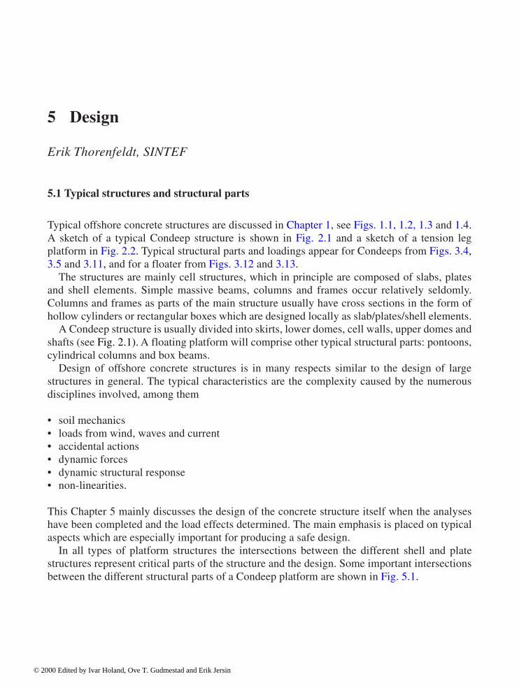
5 Design
Erik Thorenfeldt, SINTEF
5.1 Typical structures and structural parts
Typical offshore concrete structures are discussed in Chapter 1, see Figs. 1.1, 1.2, 1.3 and 1.4.A sketch of a typical Condeep structure is shown in Fig. 2.1 and a sketch of a tension legplatform in Fig. 2.2. Typical structural parts and loadings appear for Condeeps from Figs. 3.4,3.5 and 3.11, and for a floater from Figs. 3.12 and 3.13.
The structures are mainly cell structures, which in principle are composed of slabs, platesand shell elements. Simple massive beams, columns and frames occur relatively seldomly.Columns and frames as parts of the main structure usually have cross sections in the form ofhollow cylinders or rectangular boxes which are designed locally as slab/plates/shell elements.
A Condeep structure is usually divided into skirts, lower domes, cell walls, upper domes andshafts (see Fig. 2.1). A floating platform will comprise other typical structural parts: pontoons,cylindrical columns and box beams.
Design of offshore concrete structures is in many respects similar to the design of largestructures in general. The typical characteristics are the complexity caused by the numerousdisciplines involved, among them • soil mechanics• loads from wind, waves and current• accidental actions• dynamic forces• dynamic structural response• non-linearities. This Chapter 5 mainly discusses the design of the concrete structure itself when the analyseshave been completed and the load effects determined. The main emphasis is placed on typicalaspects which are especially important for producing a safe design.
In all types of platform structures the intersections between the different shell and platestructures represent critical parts of the structure and the design. Some important intersectionsbetween the different structural parts of a Condeep platform are shown in Fig. 5.1.
© 2000 Edited by Ivar Holand, Ove T. Gudmestad and Erik Jersin

120 Design
1. Lower ring beam between the cell wall, lower dome and skirt2. Upper ring beam between the cell wall, upper dome (and shaft)3. Intersection between outer caisson cells4. Intersection between joint cell wall and tri-cell walls
5.2 Design documents
5.2.1 Categories of design documents
The basis of design will be given in regulations, rules, standards, and specifications and will bea part of the contract for the design of the concrete structure. The specific basic documents tobe applied will be decided by the client to a certain extent.
In addition to standards and specifications, the design may be based on existing practice.This will typically be the case when the existing specifications are supplemented by designmethods worked out during the design of previous platforms approved by the client andpossibly by a government agency connected with petroleum affairs.
In order to provide easy access to the necessary information for the personnel in the designteams and thereby enabling them to produce a consistent design, the most important informationfrom the general documents is collected in a main document. This document is here namedDesign Basis. Where convenient, this document will give references to other basic documents.
Fig. 5.1 Typical intersection regions (nodes) in a cell structure (Gullfaks-C)
© 2000 Edited by Ivar Holand, Ove T. Gudmestad and Erik Jersin
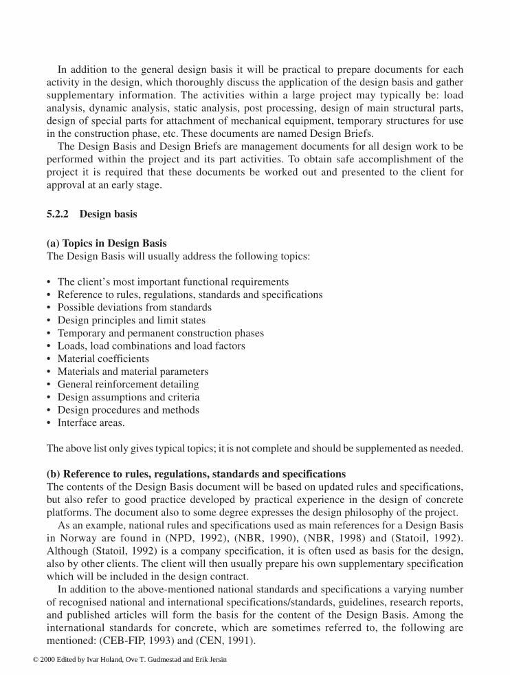
Design 121
In addition to the general design basis it will be practical to prepare documents for eachactivity in the design, which thoroughly discuss the application of the design basis and gathersupplementary information. The activities within a large project may typically be: loadanalysis, dynamic analysis, static analysis, post processing, design of main structural parts,design of special parts for attachment of mechanical equipment, temporary structures for usein the construction phase, etc. These documents are named Design Briefs.
The Design Basis and Design Briefs are management documents for all design work to beperformed within the project and its part activities. To obtain safe accomplishment of theproject it is required that these documents be worked out and presented to the client forapproval at an early stage.
5.2.2 Design basis
(a) Topics in Design BasisThe Design Basis will usually address the following topics: • The client’s most important functional requirements• Reference to rules, regulations, standards and specifications• Possible deviations from standards• Design principles and limit states• Temporary and permanent construction phases• Loads, load combinations and load factors• Material coefficients• Materials and material parameters• General reinforcement detailing• Design assumptions and criteria• Design procedures and methods• Interface areas. The above list only gives typical topics; it is not complete and should be supplemented as needed. (b) Reference to rules, regulations, standards and specificationsThe contents of the Design Basis document will be based on updated rules and specifications,but also refer to good practice developed by practical experience in the design of concreteplatforms. The document also to some degree expresses the design philosophy of the project.
As an example, national rules and specifications used as main references for a Design Basisin Norway are found in (NPD, 1992), (NBR, 1990), (NBR, 1998) and (Statoil, 1992).Although (Statoil, 1992) is a company specification, it is often used as basis for the design,also by other clients. The client will then usually prepare his own supplementary specificationwhich will be included in the design contract.
In addition to the above-mentioned national standards and specifications a varying numberof recognised national and international specifications/standards, guidelines, research reports,and published articles will form the basis for the content of the Design Basis. Among theinternational standards for concrete, which are sometimes referred to, the following arementioned: (CEB-FIP, 1993) and (CEN, 1991).
© 2000 Edited by Ivar Holand, Ove T. Gudmestad and Erik Jersin

122 Design
If, at some point, the rules put forward in the Design Basis deviate from the rules in thereferences, this should be clearly stated. All documents used in the preparation of the DesignBasis should be listed in a reference list. (c) The client’s functional requirementsThe client’s functional requirements are usually specified in a separate document, where theconditions for management and use of the structure are described. In addition to a reference tothis document it would be practical to quote for example: • Maximum and minimum deck weight with centre of gravity• Environmental loads• Lifetime of the structure• Water depths at the field• The orientation of the structure. (d) Design principlesThe structures are usually designed according to the partial safety factor method. Under certainconditions the safety of the structure may also be assessed on the basis of probabilisticmethods with specified safety indices. This approach is mainly used in connection with specialaccidental loadings.
In special cases a testing of structural parts may also be applied. It should be explicitlystated in the Design Basis document if such methods are to be applied. The structures areusually designed in the following limit states: • Ultimate limit state ULS• Serviceability limit state SLS• Fatigue limit state FLS• Accidental limit state (progressive collapse) PLS. Appropriate criteria are given for each limit state. FLS and PLS are according to internationalterminology special cases of ultimate limit states, but since fatigue and accidental actions areparticularly important for offshore structures, it is found convenient to use special identifiersfor these ultimate limit states. (e) Lifespan phasesThe lifespan of the concrete structure from the start of the construction to removal of thestructure from the field may be divided in several phases. Statoil (Statoil, 1992) distinguishesbetween temporary and permanent phases. It may be convenient to subdivide as follows: • Construction phase (temporary) includes the building of the structure. This phase is often
further subdivided.• Transport phases (temporary) include all transport of parts of the structure or the complete
structure until it is at the field, ready for installation.• Installation phase (temporary) includes the time for installation of the structure in its correct
position according to the specification of the client.• Operational phase (permanent) includes the time from completed installation to removal of
the structure.• Removal (temporary) includes the task of removing the structure from the field.
© 2000 Edited by Ivar Holand, Ove T. Gudmestad and Erik Jersin

Design 123
Different sub-phases during construction will often be decisive for the design of traditionalplatform structures. These include floating out of dock or different floating phases during furtherconstruction and especially the almost complete submersion of the structure for deck-mating. (f) Loads, load combinations and load factorsThe loads acting on an offshore concrete structure have different characteristics. As anexample, the Norwegian Petroleum Directorate (NPD, 1992) categorizes loads as permanentloads (P), live loads/variable functional loads (L), environmental loads (E), deformation loads(D), and accidental loads (A). Loads with categorization and detailed specificationsconcerning establishment of characteristic values will be provided by the client. As anexample, see (Statoil, 1992).
Usually, permanent loads from self-weight and water pressure combined withenvironmental loads due to waves and wind will have a dominating influence on the design ofthe concrete structure. Determination of the characteristic environmental loads are based onobservations at the site and the calculation of wind and sea states, according to (NPD, 1992)with 100 years return period. For serviceability limit state criteria or for temporary statesshorter return periods are used, such as 1 year.
In order to determine the static equivalent design load on the basis of dynamicenvironmental loading, separate analyses are performed which take account of the stochasticvariation of the loads and response of the structure. The designing wave load may thereforetake different values for different parts of the structure.
1. If the loads and load effects can be decided with high accuracy, the Norwegian PetroleumDirectorate may allow the use of load factor 1.2.
2. The load factor for permanent loads is set to 1.0, if this is unfavourable.3. For deformation loads from prestressing, national or regional standards may prescribe
other values.4. In the accidental limit state (PLS) it is to be checked that the damage due to accidental
loading remains local. After local damage the structure should still be able to resist definedenvironmental conditions without extensive failure, free drifting, capsizing, sinking orextensive damage to the environment.
Table 5.1 Example of load factors and combinations of loads (NPD, 1992)
© 2000 Edited by Ivar Holand, Ove T. Gudmestad and Erik Jersin
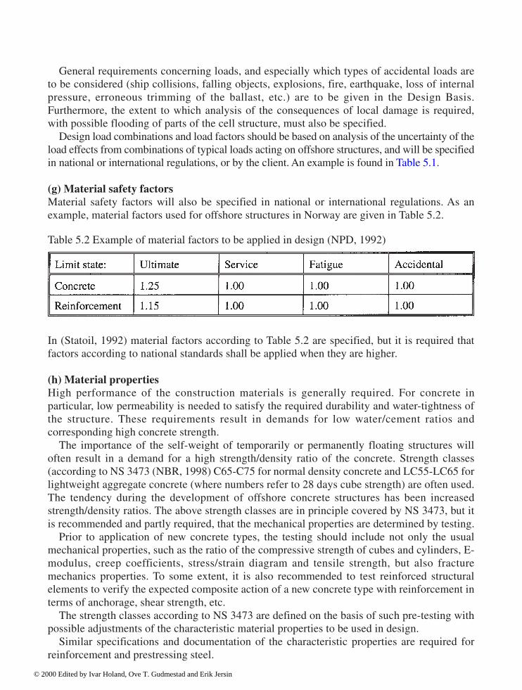
124 Design
General requirements concerning loads, and especially which types of accidental loads areto be considered (ship collisions, falling objects, explosions, fire, earthquake, loss of internalpressure, erroneous trimming of the ballast, etc.) are to be given in the Design Basis.Furthermore, the extent to which analysis of the consequences of local damage is required,with possible flooding of parts of the cell structure, must also be specified.
Design load combinations and load factors should be based on analysis of the uncertainty of theload effects from combinations of typical loads acting on offshore structures, and will be specifiedin national or international regulations, or by the client. An example is found in Table 5.1. (g) Material safety factorsMaterial safety factors will also be specified in national or international regulations. As anexample, material factors used for offshore structures in Norway are given in Table 5.2.
In (Statoil, 1992) material factors according to Table 5.2 are specified, but it is required thatfactors according to national standards shall be applied when they are higher. (h) Material propertiesHigh performance of the construction materials is generally required. For concrete inparticular, low permeability is needed to satisfy the required durability and water-tightness ofthe structure. These requirements result in demands for low water/cement ratios andcorresponding high concrete strength.
The importance of the self-weight of temporarily or permanently floating structures willoften result in a demand for a high strength/density ratio of the concrete. Strength classes(according to NS 3473 (NBR, 1998) C65-C75 for normal density concrete and LC55-LC65 forlightweight aggregate concrete (where numbers refer to 28 days cube strength) are often used.The tendency during the development of offshore concrete structures has been increasedstrength/density ratios. The above strength classes are in principle covered by NS 3473, but itis recommended and partly required, that the mechanical properties are determined by testing.
Prior to application of new concrete types, the testing should include not only the usualmechanical properties, such as the ratio of the compressive strength of cubes and cylinders, E-modulus, creep coefficients, stress/strain diagram and tensile strength, but also fracturemechanics properties. To some extent, it is also recommended to test reinforced structuralelements to verify the expected composite action of a new concrete type with reinforcement interms of anchorage, shear strength, etc.
The strength classes according to NS 3473 are defined on the basis of such pre-testing withpossible adjustments of the characteristic material properties to be used in design.
Similar specifications and documentation of the characteristic properties are required forreinforcement and prestressing steel.
Table 5.2 Example of material factors to be applied in design (NPD, 1992)
© 2000 Edited by Ivar Holand, Ove T. Gudmestad and Erik Jersin

Design 125
(i) Reinforcement principlesThe Design Basis document should outline the basic principles for the reinforcement system inorder to ensure a unified detailing of the reinforcement in the whole structure. This willtypically comprise the required minimum reinforcement, maximum spacing, standard bendingdiameters, methods and standard dimensions of splices and anchorages, limitations ofmaximum reinforcement density; use of bundled bars, etc. The prestressing system withstandard cable dimensions will also be specified in the Design Basis. (j) Design assumptions and criteriaThe main parts of a concrete platform are classified in a high safety class taking into accountthat a failure situation may result in catastrophic consequences with high risk for loss ofhuman lives. The extent of control measures is to be evaluated especially. Regarding control ofthe design and construction, reference is made to Chapters 6 and 7. Examples of relevantspecifications are:
For the serviceability limit state: • design exposure class (with corresponding concrete cover and crack widths)• structural requirements to ensure strict water tightness• criteria concerning vibrations and displacements, especially for shaft structures. For the fatigue limit state: load distribution spectra and lifetime factors.
For dimension tolerances:
• thickness of each structural part• deviations from the intended centre line of the components• concrete cover• position of the reinforcement.• deviations from the ideal middle plane of the structure (as a basis for the design of slender
shell structures). (k) Design procedures and methodsProcedures and methods which are not uniquely described in the reference documents shouldbe specified in the design basis. Examples may be:
• Load effects calculated by linear finite element analysis may be used as the main basis ofdesign of the concrete structure
• Detail design of regular sections of the structure performed by automatic post-processing ofthe analysis results
• The method to be used in transverse shear capacity control• Effect of water pressure in cracks• Practicable simplifications and approximations for design for restraint forces due to
imposed deformations• Analysis and design for inward buckling (implosion)
© 2000 Edited by Ivar Holand, Ove T. Gudmestad and Erik Jersin

126 Design
• Additional design tasks which are not naturally included in the general design of thestructure, like embedded steel structures, crane support structures, tube penetrations,temporary block-outs, etc.
• interface areas to other main parts of the concrete structure and to other design disciplinesrequiring procedures regarding management of interface information and co-ordination.Practical experience has shown that it is a considerable challenge to handle all theinformation necessary to satisfy all the different requirements in such interface areas, andthat this is a source of possible design errors.
An example of the last item is that an offshore oil production platform will be equipped with alarge number of tubes which are originally planned and designed by designers in otherdisciplines. The connection of such tube systems to the concrete structure will often requirespecific limitations of the load effects (deformations) in certain regions of the concretestructure. The technical solution to such problems should be worked out in close co-operationbetween process equipment and concrete structure designers to ensure that the combinedstructure performs as planned and the integrity of the concrete structure is taken care of.
5.2.3 Design briefs
(a) Needs for design briefsIn addition to the Design Basis document, a series of sub-documents in the form of designbriefs for each main activity, such as load analysis, structural FEM analysis and detail designof each main part of the structure should be worked out as part of the Design Briefs. The basisfor the Design Brief for a part of the concrete structure will be:
• relevant results obtained in the concept development phase• drawings of the geometry of the part• relevant parts of the Design Basis explaining how the loads are carried by the structure• construction phases and limit states the structural part is to be designed for. The Design Brief will be an extension and further detailing of the general topics in the DesignBasis. The outline of the Design Briefs should be similar, but the topics to be discussed may varydepending on the type of activity or type of structure. The Design Brief will also include adescription of how the design work is to be performed. It is often experienced that questions of acharacter where clarification with the client is necessary arise during the preparation of the DesignBrief. The document will therefore also be helpful in clarification of all important questions indue time before starting the work-intensive production of design documents and drawings.
The following list of typical topics to be discussed in the design brief is not complete andshould be supplemented in each case:
• Define documents and drawings to be produced within the activity• Depict and describe the configuration of the structural part• Describe interfaces to other parts and disciplines• Indicate key data of load effects and geometry
© 2000 Edited by Ivar Holand, Ove T. Gudmestad and Erik Jersin

Design 127
• Describe the structural system• Describe relevant construction phases and load combinations• Indicate all construction phases and limit states to be checked• Describe the load effects included in the global element analyses• Describe analyses methods for load effects not included in the global analyses• Describe design methods and design sections to be applied• Reinforcement system and standard detailing, prestressing system and configuration• Criticality and sensitivity assessment• Indicate the relevant post-processing files• Discuss the implementation of the quality assurance system for the particular task. DocumentationA comprehensive list of documents and drawings necessary for the documentation of thedesign should be worked out. This list represents a survey of the work to be carried out andmay be used to check that all design tasks are included in the work plan. It is alsorecommended that the document hierarchy is depicted. The purpose of this illustration is toshow the relation between the design documents and the regulatory documents providing thebasis for the design. (b) Configuration and key dataDescriptions and drawings showing the configuration of the total structure and the actualstructural part in particular, including the main construction phases and working joints, willprovide the necessary comprehension and may serve as a reference for descriptions andevaluations performed during the detail design.
The key data for geometry and loads will typically comprise the concrete volume,anticipated amount of reinforcement and prestressing steel, buoyancy volumes, cell areas,resulting beam forces in shafts, global forces to be transferred to the sea bottom, etc. Thisinformation facilitates the designers’ assessment of the sensitivity of the detail design, i.e. theimportance of changes and adjustments of the loads or dimensions occurring during the detaildesign process. (c) Interfaces to other structural parts and disciplinesInterfaces between different design tasks and how information should be handled are usuallydescribed in separate documents. Further discussion is included in the design brief ifnecessary. When the design of large structures is sub-divided and allocated to several separatedesign teams, the design criteria of one part of the structure must be fully compatible with theneighbouring parts, for example co-ordination of the use of prestressing in different main partsof the structure.
A table of important deadline dates for delivery of input data necessary for the designprocess to progress according to plan may be included. In addition, notice should be given indue time during the process. (d) Structural systemThe global structural system is described in brief. An explanation of how the loads will becarried by the actual part of the structure is emphasized. This information is important in order
© 2000 Edited by Ivar Holand, Ove T. Gudmestad and Erik Jersin

128 Design
to provide the detail designers with a general view on the design task and help them inunderstanding the structural behaviour. (e) Construction phases and load combinationsThe design loads are established by scaling the unit load cases used in the analysis bymultiplication with scaling factors for the characteristic value and load factors according to theactual limit state and load combination. Each load combination consists of a number of unitload cases which are scaled and added by linear superposition.
Equilibrium Load Cases consist of a set of active loads (self weight, self weight andfunctional loads on deck structure, weight of equipment, weight of ballasting, water pressureand environmental loads) and reaction loads (reactive soil pressure on ground based structuresin operational phase or buoyancy forces and reaction forces in tethers in floating phases).
In the operational phase the structure will be designed for possible variation of the deckweight, variation of the effect of prestressing and the effect of waves and wind in variousdirections. Furthermore, the possibilities of different possible distributions of the soil reactionsare usually accounted for. Assume that a design section in the structure is to be designed inUltimate Limit State for: • 12 different wave directions• 2 deck weights (max and min)• 2 soil pressure distributions• 2 effects of prestressing (max and min)• 2 load combinations (a and b in ultimate limit state). The example results in 192 load cases which are to be checked. The number of load casesincreases considerably in dynamic and fatigue response calculations.
As mentioned in Section 5.2.2, the lifetime of the structure consists of several phases. Thetotal number of phases will mainly depend on the number of sub-phases during construction.The transportation, installation, operation and removal phases will exist for all typical offshorestructures.
Due to the large number of load combinations and construction phases it is practical toassess which combinations/phases will certainly not be decisive in the design and can thereforebe excluded. This evaluation is commonly based on simplified calculation methods of thesame type as also used in the verification of the design (see Chapters 3 and 7). The results ofthese calculations are included in a separate load-phase document.
An abstract of this document explaining for which construction phases design calculationsare to be made and which load combinations and limit states are to be checked in each phaseshall be included in the Design Brief. The principles for establishment of the design loadcombinations should also be included. However, the detailed combination of unit load casesused in the analysis will be described in separate referenced documents.
All special load combinations which are not included in the global analysis must bedescribed and explained in detail, to avoid time-consuming discussions at a later stage. Typicalexamples are combinations with local loads such as ship collisions and impact from fallingobjects, local implosion or other non-linear effects.
© 2000 Edited by Ivar Holand, Ove T. Gudmestad and Erik Jersin

Design 129
(f) Analysis and design methodsThe general design methods are described at a suitable detail level in the Design Brief and/orwith reference to the Design Basis. A complete list of all relevant analysis result files to beused in the post-processing design of the actual part of the structure should be worked out.Identification of the person responsible for the verification of the analysis and reference to theverification report should also be stated here.
The element mesh used for the actual part of the structure is described and depicted withclear indication of the areas of the structure where the results of the analysis are assumed not tobe sufficiently accurate and modification is needed. All elements where the analysis resultswill not be used as a basis for the post-processing should be identified in the Design Basis.
Reference is made to other documents where the general use of linear element analysis andthe automatic post-processor based design are described in detail. In the Design Brief, alldesign sections to be used by the post-processor for calculation of the section forces based onintegration of the analysis output stresses, are depicted. The selection of design sectionsamong all accessible integration points in the analysis should be explained and justified.
It is often necessary to select a supplementary design section which does not correspond tothe integration points in the analysis. The method of establishing the section forces in suchcases should be explained, especially when the forces in sections at the border of structuralintersections are determined by extrapolation from the forces in neighbouring design sections.
Supplementary analysis and design programs and manual design methods to be applied inthe design of areas with concentrated loads or complex geometry, where direct post-processingof the global analysis results are not applicable, should be described in detail. Typicalexamples are the design of intersection areas and analysis/design for implosion and impactfrom ship collision and falling objects. Furthermore, relevant design methods to be appliedwithin the category Miscellaneous Design (see Section 5.2.2.11) should be described.
It is recommended that all relevant supplementary design methods including assumptions,limitations and how the design results are to be co-ordinated with the results of the general post-processing, are clarified and approved by the client’s revision of the Design Brief at an early stage. (g) Reinforcement system and detailingGeneral principles for detailing of the reinforcement are described in the Design Basis. Theseprinciples are adapted to the main configuration of the actual structural members and furtherspecified in the Design Brief. The reinforcement system is to be fully defined here. Thereinforcement system includes definition of the number of reinforcement layers withdirections relative to the defined principal directions of the structural part and position relativeto the concrete surface. Furthermore, standard diameters for the main and shear reinforcementand the maximum number of bars in reinforcement bundles are to be stated.
The reinforcement system is input data to the post-processor and defines the standardamounts to be used in the design iterations performed by the processor to obtain the necessarypractical reinforcement. The reinforcement system will also provide the basis for thegeneration of general reinforcement drawings showing the selected standard amounts and theoverlap splicing system for the reinforcement in slip-formed structures.
Typical reinforcement configuration drawings of typical intersection areas should also beprepared to ensure efficiency and constructability in areas with complex geometry.
It is also practical to define standard anchorage and lap splicing lengths dependent on thereinforcement dimensions and other influencing parameters according to the concrete design
© 2000 Edited by Ivar Holand, Ove T. Gudmestad and Erik Jersin
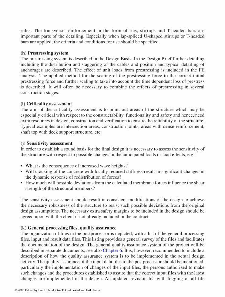
130 Design
rules. The transverse reinforcement in the form of ties, stirrups and T-headed bars areimportant parts of the detailing. Especially when lap-spliced U-shaped stirrups or T-headedbars are applied, the criteria and conditions for use should be specified. (h) Prestressing systemThe prestressing system is described in the Design Basis. In the Design Brief further detailingincluding the distribution and staggering of the cables and position and typical detailing ofanchorages are described. The effect of unit loads from prestressing is included in the FEanalysis. The applied method for the scaling of the prestressing force to the correct initialprestressing force and further scaling to take into account the time dependent loss of prestressis described. It will often be necessary to combine the effects of prestressing in severalconstruction stages. (i) Criticality assessmentThe aim of the criticality assessment is to point out areas of the structure which may beespecially critical with respect to the constructability, functionality and safety and hence, needextra resources in design, construction and verification to ensure the reliability of the structure.Typical examples are intersection areas, construction joints, areas with dense reinforcement,shaft top with deck support structure, etc. (j) Sensitivity assessmentIn order to establish a sound basis for the final design it is necessary to assess the sensitivity ofthe structure with respect to possible changes in the anticipated loads or load effects, e.g.:
• What is the consequence of increased wave heights?• Will cracking of the concrete with locally reduced stiffness result in significant changes in
the dynamic response of redistribution of forces?• How much will possible deviations from the calculated membrane forces influence the shear
strength of the structural members? The sensitivity assessment should result in consistent modifications of the design to achievethe necessary robustness of the structure to resist such possible deviations from the originaldesign assumptions. The necessary extra safety margins to be included in the design should beagreed upon with the client if not already included in the contract. (k) General processing files, quality assuranceThe organization of files in the postprocessor is depicted, with a list of the general processingfiles, input and result data files. This listing provides a general survey of the files and facilitatesthe documentation of the design. The general quality assurance system of the project will bedescribed in separate documents; see also Chapter 6. It is, however, recommended to include adescription of how the quality assurance system is to be implemented in the actual designactivity. The quality assurance of the input data files to the postprocessor should be mentioned,particularly the implementation of changes of the input files, the persons authorized to makesuch changes and the procedures established to assure that the correct input files with the latestchanges are implemented in the design. An updated revision list with logging of all file
© 2000 Edited by Ivar Holand, Ove T. Gudmestad and Erik Jersin

Design 131
changes must be available. The revision log must include the dates of implementation, thecause of the changes and the person responsible. The revision list of each file mayconveniently be included in the heading.
5.3 Design procedures
5.3.1 Design process
In Sections 5.4 and 5.5 the design activities, i.e. the design and detailing of the main concretestructural parts are discussed. For further discussion of the analysis, reference is made toChapters 3 and 4.
All personnel performing technical tasks must know the content of the Design Basis andunderstand the application of this document in their own work. Furthermore, the personnelmust be familiar with the content and application of the Design Brief for the actual part ofstructure where they are involved in the design. Fig. 5.2 shows a simplified flow chart of thedesign process based on the use of a postprocessor.
The design of concrete sections is based on integrated load effects from the finite elementanalysis; see also Chapter 3. Due to the large number of load cases and sections to be checked,a high degree of automation of the design process is necessary. As far as possible apostprocessor is used as a design tool.
It is important to be aware of the inherent limitations of the validity of a section-by-sectiondesign based on forces from linear elastic analysis. The linear analysis cannot simulate allimportant load effects with satisfactory accuracy. Local analysis and manual design musttherefore supplement the analysis. The results of the supplementary design are added to orsubstitute the results from the postprocessor.
An automatic design process represents a demanding challenge to the designer regarding athorough assessment of the results. Independent simplified calculations must be done to verifythat the calculated amounts of reinforcement and utilization of the concrete sections arereasonable. See also Chapter 3 (Simplified analysis) and Chapter 6 (Verification).
5.3.2 Postprocessor
This section gives a brief description of the postprocessor and the limitations in the use of sucha program. The function of the postprocessor is not, however, explained in detail. A moreextensive description of the design of offshore concrete structures based on processing ofresults from finite element analysis is given in (Brekke, Åldstedt and Grosch, 1994). Furtherdetails may be found in the user’s manuals for the respective postprocessing programs.
The detail design is performed in a set of representative sections throughout the structure.The structure may conveniently be divided in horizontal sections (H.S) and vertical radialsections at constant angles (f-sections or F.S). A simple example showing the design sectionsin a cylindrical structure is shown in Fig. 5.3. The design points are determined by theintersections of the horizontal and vertical sections.
© 2000 Edited by Ivar Holand, Ove T. Gudmestad and Erik Jersin
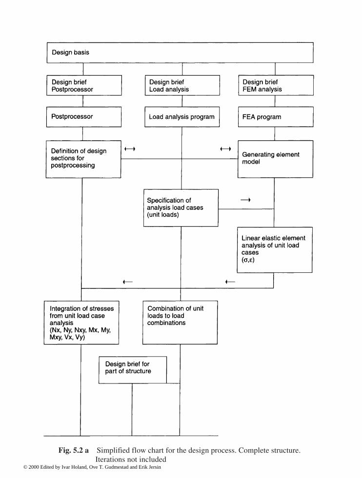
Fig. 5.2 a Simplified flow chart for the design process. Complete structure.Iterations not included
© 2000 Edited by Ivar Holand, Ove T. Gudmestad and Erik Jersin

Fig. 5.2 b Simplified flow chart for the design process for part of structure. Iterations not included
© 2000 Edited by Ivar Holand, Ove T. Gudmestad and Erik Jersin
134 Design
The number and position of the integration points (Gauss-points), where the stresses may beintegrated by the postprocessor, is determined by the choice of the finite element model andthe type of elements. The choice of the element mesh for the analysis also decides the possiblelocations of the design points. Good communication between the analysis team and the teamresponsible for the postprocessing is required to ensure that the practical use of the analysisresults in the detail design is considered in the element mesh development.
The general requirements concerning the element modelling are discussed in Chapter 3.The element size should be reduced towards the borders with high stress gradients to
achieve sufficient accuracy. Rectangular elements should be used as close to the borders of thestructures as possible. The use of skew elements with reduced accuracy and complexinterpretation of the section forces is often unavoidable in intersection regions between theregular structural main parts (see Fig. 5.1).
Forces at the borders of the intersection regions are often needed in practical design. Thesimplest way is to define a design section at the border. Usually these sections do notcorrespond to the integration points of the elements. The section forces are therefore often
Fig. 5.3 Division of a cylindrical shell in design sections. * The section forces in the border sections are determined by extrapolation
© 2000 Edited by Ivar Holand, Ove T. Gudmestad and Erik Jersin

Design 135
extrapolated from the results at integration points further into the regular part of the structure.Extrapolation methods are discussed in Chapter 3.
Acceptably small analysis errors in regular design points are easily unacceptably enhancedby extrapolation. The accuracy must be closely validated. All regions of the structure where theanalysis is expected to give an inaccurate result should be documented in a separate report.This report should be used actively in the design process to ensure that supplementary analysisof these regions is carried out.
In regions with varying shell thickness it is especially important to choose the position anddirection of the design section in order to obtain representative section forces. Sections normalto the middle plane of the elements are usually preferable (see Chapter 3).
The design is based on the shell section forces at each design point. The shell section forcescan be regarded as a combination of in-plane membrane forces and slab section forces(bending moments, torsional moment and out-of-plane shear forces).
This is illustrated in Figs. 5.4–5.6 by application of the forces on two faces of a finiteelement.
In reality it is the forces acting in different directions in defined single points (representedby a line through the thickness) which are the basis of the design.
The postprocessor divides the sections in a series of concrete layers (lamellas) and definesthe direction and position of each reinforcement layer. The design for membrane forces and
Fig. 5.4 Membrane forces (Nx, Ny, Nxy). Fig. 5.5 Slab section forces (Mx, My, Mxy, Vx, Vy).
Fig. 5.6 Shell section forces (Nx, Ny, Nxy, Mx, My, Mxy, Vx, Vy).
© 2000 Edited by Ivar Holand, Ove T. Gudmestad and Erik Jersin

136 Design
moments is based on strain compatibility with the assumption that plane sections remainplane. The non-linear material properties of concrete and reinforcement are taken into account.The processor calculates the response of the section-to-section forces by an incrementaliterative solution procedure. If the design criteria are not met, the processor automaticallyincreases the reinforcement in predefined steps and finally checks that the design strengths ofthe concrete lamellas are not exceeded.
The out-of-plane shear forces are not included in the response calculation. The shearcapacity is checked analytically in accordance with the methods in relevant concrete designcodes or standards, usually by a simplified method.
The water pressure is regarded as a load at the surface of the structure in the global analysis.The effect of water pressure penetrating into cracks is therefore calculated by a special routinein the postprocessor (see Section 5.4.3).
The iterative design based on response calculation followed by an incremental increase ofthe reinforcement and recalculation in several steps is a time-consuming process. Thecalculation time can be reduced by the choice of reasonable starting conditions in terms ofreinforcement amounts and initial strain.
A practical method to establish reasonable reinforcement amounts at an early stage is tostart the processing with a few selected load combinations which are assumed to be decisive.Based on the result of the concept study phase it is often possible to point out the loadcombinations and load cases which will decide the necessary reinforcement in the major partsof the structure. The required minimum reinforcement in the respective structural memberswill be a convenient initial choice for this pre-processing. The preliminary results will still beat hand within a reasonably short time due to the few load cases. Experience shows that thispreprocessing will provide a good basis for the selection of the initial reinforcement amountsin the final processing of the vast number of load cases in the final design.
The necessary reinforcement in each single design point will vary according to the variation ofthe section forces. For practical reasons it is necessary to simplify the reinforcement. The possibilityof defining regions of the structure with constant reinforcement amount as input data is thereforea necessary feature of the post-processor program. It is often practical to define different constantreinforcement regions for each principal reinforcement direction and layer. Separate proceduresare developed for the definition of the staggering of the shear reinforcement.
Due to the large amount of input data to be handled in the design of a complex structure, astrict accountancy of the use of the postprocessor is necessary. The limited number of personsauthorized to make changes in the input data should be listed in the Design Brief. An updatedrevision list with logging of all file changes must be available. The revision log must includethe dates of implementation, the cause of the changes and the person responsible. The revisionlist of each file may conveniently be included in the heading. It is also essential that all resultfiles clearly state all input data. The key word is traceability.
The postprocessor manuals should provide the designer with easy access to all necessaryinformation for an optimal utilization of the design tool. The manuals must include the basicdesign formula and criteria and clear statements regarding the limitations of the validity of theprogram. The manuals will conveniently comprise a general part followed by designspecifications with optional design criteria adaptable to different kinds of structures.
During the design process it may be necessary to change the design parameters, e.g. theconcrete strength class. It is therefore important that the processor is prepared for a flexible
© 2000 Edited by Ivar Holand, Ove T. Gudmestad and Erik Jersin
Design 137
implementation of such changes. The designer will sometimes also change the designparameters in order to assess the robustness/sensitivity or criticality of the design.
The postprocessor should be prepared for use together with the most commonly used finiteelement programs. It will be advantageous if it also is easily adapted to other FE programs. Aflexible postprocessor in this respect will provide a freedom of choice of the analysis programthat is best suited for the present task.
The postprocessor will utilize a lot of information concerning the concrete structure alreadyexisting in the finite element program employed in the analysis of the structure. Thepostprocessor should be able to retrieve all relevant information from the analysis result fileswithout time-consuming manual data input. The print and plot facilities of the postprocessorprogram should provide simple selection of optional result presentations in the form of resulttables and/or graphical presentations.
In addition to automatically generated result tables containing the main results only, itshould be possible to easily generate more detailed information tables. Such tables mayconcern specified sections containing, e.g. section geometry data, load combination, sectionalforces, strain result vector, stresses in concrete, normal and shear reinforcement andsummarized design results in terms of Utilization Ratios (UR).
The design load combination will generally consist of several basic load cases. Easy access tothe listing of all basic load cases with scale factors and the corresponding contribution to thesection forces are necessary processor facilities to enable the designer to perform simple checkingof the section forces. This is very important in order to achieve correct and reasonable results.
Plotting of the distribution of forces and reinforcement amounts with correspondingcapacity along the structure should be emphasized. Graphical presentations will often be themost effective means for assessment of the design results.
The processor program should have a low user threshold with easy access to the input andoutput files. In large projects new personnel will frequently join the design team withoutexperience in the use of the design tool. It is therefore important that inexperienced personnelcan quickly grasp the details of the standard use of the program.
The postprocessor should be flexible as regards the adaptation to various types of hardware.Preferably it will be adaptable to large computers, workstations and Personal Computers. Itought to be the extent of the design task, not the structure of the postprocessor, which decidesthe necessary hardware.
It is, however, important that sufficient computer capacity is available. The timeconsumption running the processor should not have too much influence on the progress of thedesign work. It should at least be possible to start running a fairly large design task, e.g. aspherical shell, at the end of a workday and receive the result file ready for assessment andfurther adaptation the next morning.
Periodically the design tool will be used intensively. Often several large design jobs will beperformed during the same period within strict time limits. It is important to establish efficientsupport functions by computer experts. Possible errors or defects occurring during theintensive design periods must be corrected without delay. The support team should also bereadily available to answer questions concerning the advanced use of the postprocessor beyondwhat is naturally included in the manuals.
Especially in the start-up phase of the detail design process it will be necessary to performconsiderable manual operations, e.g. to get the processor operative, and there will be a
© 2000 Edited by Ivar Holand, Ove T. Gudmestad and Erik Jersin
138 Design
relatively high risk that human errors will occur. This again emphasizes the importance of aresponsible and critical use of the automatic design tool. The results should be criticallyassessed and not be regarded as an authorized answer to correct design.
All software to be deployed in detailed design of marine concrete structures is to be verifiedfor this application (NPD, 1992).
The ISO standard (ISO13819 Part 3) will, when available, for design refer to NS 3473 as astandard that covers relevant conditions (see Chapter 1, Section 1.6.2). It will still be advantageousfor further international application if the postprocessor also has the possibility of performingthe design checking according to other standards, e.g. the British Standard (BS), Canadian Standard(Can Standard) or the American ACI codes, and Eurocode 2. Design according to other codes isalready implemented in some of the existing postprocessors. In any case, the postprocessor programshould be prepared for easy implementation of optional design codes.
5.3.3 Effect of water pressure in cracked concrete
(a) GeneralMarine structures may be exposed to very high water pressure. For example, the water pressureat 250 m depth corresponds to a load of 250 tonnes per square metre, or a surface stress of 2.5MPa. The design tensile strength of C65 concrete according to NS 3473 also equals 2.5 MPa.This implies that existing structures are exposed to water pressure of the same order ofmagnitude as the tensile strength of the concrete.
In a concrete body with unsealed surfaces exposed to high water pressure the internal porepressure will gradually increase. Ordinary concrete contains pores in a wide range of relativesizes with different fluid surface stresses. It is therefore difficult to measure directly arepresentative “effective” pore pressure in the material. The notion of the effective porepressure is therefore based on the interpretation of the observed influence on strain andstrength of concrete exposed to high water pressure.
Measured strain and strength of 100 mm concrete cubes with or without sealing of the surfaceexposed to high water pressure (800 m water head) show that the build-up of pore pressure insidethe concrete is strongly material- and time-dependent (Bjerkeli, 1990). The results indicate that anear 100% effective pore pressure can develop in small specimens of ordinary porous concrete(C25—C35) in a few days. For high strength concrete (strength class higher than C65) the porepressure development will take months, and the maximum effective pore pressure will finally beabout 60–90%. For high-strength lightweight aggregate concrete the eventual pore pressuredevelopment may take a very long time, probably due to the combination of low permeability ofthe high strength mortar and large pore volumes in the lightweight aggregate.
For thick structures with the actual concrete types used in marine structures the developmentof pore pressure will generally take a long time. In structures exposed to water pressure on oneside, the pore pressure will probably stabilize with a gradually decreasing pore pressure fromthe exposed outside towards the inside, but the pore pressure gradient is not necessarily linear.
If the structure has visible cracks with open communication with the exposed surface, it isnaturally assumed that the water will penetrate into the crack with a constant water pressure equalto the external pressure action on the crack surfaces. The effect of the water pressure will be a localwedge effect which will affect the state of equilibrium of the cracked section of the structure.
© 2000 Edited by Ivar Holand, Ove T. Gudmestad and Erik Jersin

Design 139
Obviously, the effect of high water pressure in cracks must be taken into account, due totensile stresses induced by direct loading or restraining of imposed deformations. It is a matterof discussion to which extent it is also necessary to take into account the effect of possiblewater pressure in arbitrary internal cracks without direct communication with the exposedsurface, due to local stresses in the interior of the concrete sections. A design philosophy basedon the assumption that cracks with full water pressure can occur in arbitrary locations anddirections anywhere in the concrete members will consequently lead to extreme situationswhere, for example, the spalling off of the concrete cover is unavoidable. (b) Calculation of section forcesIn a generally formulated clause in NS 3473 it is suggested that the water pressure in thestructure should be taken into account. In clause 9.4.7 it is stated:
Potential fluid or gas pressure in pores or cracks shall be accounted for instructures exposed to direct pressure from fluid or gas in the calculation offorces and moments if this increases the action effects or reduces the capacity.
For thick shell structures it will generally be significant for the calculation of the section forces inthe structure, whether the water pressure load is assumed to act on a presumed watertight surface,or the pressure is assumed to act deeper in the structure, e.g. at the middle plane of the shell.
In regular cases with external water pressure the penetration of water into the concrete willlead to reduced forces on the structure. For example, the horizontal force in the hoop directionof a cylindrical platform shaft with external water pressure will decrease approximatelyproportionally to the ratio between the middle and the outer diameter of the shaft. Also themoments and the shear forces at the shell borders will usually decrease (as opposed to apressure vessel with internal pressure where the section forces tend to increase).
It is therefore conservative to assume that the water pressure acts on the outer surface.Furthermore, when the structure is modelled with volume elements it will be morecomplicated to depart from the usual finite element method routine for application ofdistributed load on the element surfaces.
In most cases it is therefore accepted that the water pressure is applied on the surface in thestructural analysis. It is, however, important to be aware of this assumption and take intoaccount the effects of water pressure in cracks and pores by the capacity check of each singlesection and local areas of the structure. (c) Design for axial forces and moments by water pressure loadsIn ultimate limit state design it is usually assumed that concrete cannot transfer tensileresultants. By calculation of the resistance to actual forces and moments it is assumed that thetensile strength of the concrete is zero and that cracks will occur in the tensile zones of thestructure. The capacity check of a section is at first calculated without water pressure. If thetensile face is exposed to water pressure the wedging effect of water pressure in the crack istaken into account as an external tensile force calculated as the resultant of a constant pressureon the crack surface, and a new state of equilibrium is calculated. The tensile force resultantcontributes to the moment as well as the axial force in the section.
In the general case, where the sections are checked by a postprocessor, the section issubdivided in several layers. The tensile forces from the water pressure are applied in eachlayer with direction normal to a calculated crack direction, i.e. in the principal tensile strain
© 2000 Edited by Ivar Holand, Ove T. Gudmestad and Erik Jersin

140 Design
direction. In general, this direction will vary from layer to layer. For practical reasons the waterpressure is applied in all layers where the minimum compressive stress is less than the waterpressure. The consequence of this is that elements that are not subjected to significant biaxialmoments with equal signs, or biaxial membrane compression, may be subjected to tensilestresses from the water pressure in all layers but with varying direction.
Application of water pressure load as tension in the principal strain direction of the layerswill generally increase the necessary reinforcement and appears to be a safe method forcalculation of the effects of water pressure on the axial force and moments in the ultimate limitstate. Naturally the importance of the water pressure varies with the force of the waterpressure. The relative influence on the reinforcement demand is more significant in areas of thestructure with small reinforcement amounts near the required minimum reinforcement. (d) Design for shear force due to water pressure loadDesign for shear force in slabs and shells is usually based on the “simplified method”according to NS 3473. The method includes a considerable “concrete contribution”, whichincreases significantly in structures with axial compression force, and a contribution fromshear reinforcement based on the standard truss model with 45 degree compression diagonals.It is usually accepted that shear reinforcement (stirrups) can be omitted in areas where theconcrete contribution to the shear strength is sufficient.
Calculation of necessary stirrup reinforcement in loaded areas near the supports and designrules for necessary shear reinforcement are based on the usual cases where the load is appliedby compression against the top side of the structure with respect to the direction of the load andthe support forces are transferred by compression against the under side. If the loads or supportreactions are imposed on the structure in such a way that internal tensile forces occur in thedirection of the load, it is required that these forces are carried by the reinforcement.
When the loads are caused by compression from fluid (or gas), the pressure may penetrate intoshear cracks and influence the transfer of loads to the structure in a way which is comparable tosuspended (hanging) loads. The transfer of water pressure load will, however, be distributedthrough the thickness of the structure and thereby not be quite as unfavourable as suspendedloads. On the other hand, it may be argued that the concrete contribution to the shear strengthmay be further reduced if water pressure of the same order of magnitude as the tensile strength ofthe concrete is allowed to penetrate into the structure. This particularly concerns the upper limitof the concret e contribution in the design formula in NS3473 which is clearly related to thecriteria that the principal tensile stress at the centre of the section equals the tensile strength ofthe concrete. Activation of shear reinforcement presupposes that inclined shear cracks exists.Such cracks, however, do not have direct communication with the water-exposed surface.
Fig. 5.7 shows the required shear capacity related to the shear force diagram of a memberwith constant distributed load. The stapled capacity diagram for members with suspended loadwell above the shear force diagram is recommended also for structures with water pressureloading. No reduction is made for loads near the support. This means that the maximum shearforce at the edge of the support should be accounted for.
As mentioned in Section 5.4.3, the necessary tensile reinforcement is increased due to theeffect of water pressure normal to the bending cracks. If the main tensile reinforcement isstaggered, the effect of inclined shear cracks is considered by extending the reinforcement alength equal to the internal lever arm (z) with an additional (full) anchorage length beyond thesection where the actual part of the reinforcement may theoretically be terminated.
© 2000 Edited by Ivar Holand, Ove T. Gudmestad and Erik Jersin

Design 141
According to the simplified method in NS3473 a compressive axial force will increase theshear capacity considerably. It is recommended that the axial force calculated by the globalanalysis with water pressure at the external surface is conservatively reduced by a forceresultant corresponding to full water pressure in the section area.
The upper limit of the shear capacity formula will often be decisive for structural members withhigh compressive axial force. When high compressive stresses exist in the principal shear directionof a slab or shell or, maybe more often, normal to this direction, the tensile strength in the thirdprincipal direction will decrease. A full utilization of the shear strength according to the simplifiedmethod for members without shear reinforcement may in such cases turn out to be non-conservative.
Application of the alternative truss model method for shear design will result in a generalneed for shear reinforcement in all members subjected to transverse shear. This seemsunnecessaryly conservative for slabs and shells in general.
Methods based on the modified compression field theory (MCFT) (Collins and Michell,1991) represent a further option which is also introduced in the so-called general method inNS3473. This method is primarily intended for members with in-plane shear, but is alsoapplicable for beams and slabs with shear reinforcement.
Based on the notion of the mean tensile strength of cracked (reinforced) concrete and theability of shear transfer in cracks, the method also features a “concrete contribution” to theshear strength, but the method is apparently not sufficiently well verified to be applied in theshear design of members without shear reinforcement. The need for minimum shearreinforcement in platform structures is further discussed in Section 5.4.3.
(e) Water pressure in the nodes of the structureThe possibility that transverse loads from external water pressure will be transferred to thestructure in shear cracks is indirectly taken into account in the design of regular members. Thetransverse component of the pressure on the inclined crack surfaces will substitute thetransverse load at the outer surface in the same area.
Fig. 5.7 Curtailment of shear reinforcement by distributed load. Simplified method
© 2000 Edited by Ivar Holand, Ove T. Gudmestad and Erik Jersin
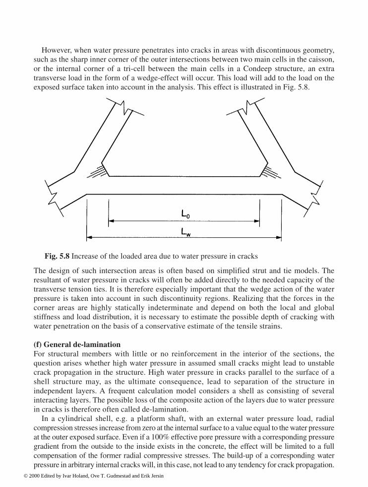
142 Design
However, when water pressure penetrates into cracks in areas with discontinuous geometry,such as the sharp inner corner of the outer intersections between two main cells in the caisson,or the internal corner of a tri-cell between the main cells in a Condeep structure, an extratransverse load in the form of a wedge-effect will occur. This load will add to the load on theexposed surface taken into account in the analysis. This effect is illustrated in Fig. 5.8.
The design of such intersection areas is often based on simplified strut and tie models. Theresultant of water pressure in cracks will often be added directly to the needed capacity of thetransverse tension ties. It is therefore especially important that the wedge action of the waterpressure is taken into account in such discontinuity regions. Realizing that the forces in thecorner areas are highly statically indeterminate and depend on both the local and globalstiffness and load distribution, it is necessary to estimate the possible depth of cracking withwater penetration on the basis of a conservative estimate of the tensile strains. (f) General de-laminationFor structural members with little or no reinforcement in the interior of the sections, thequestion arises whether high water pressure in assumed small cracks might lead to unstablecrack propagation in the structure. High water pressure in cracks parallel to the surface of ashell structure may, as the ultimate consequence, lead to separation of the structure inindependent layers. A frequent calculation model considers a shell as consisting of severalinteracting layers. The possible loss of the composite action of the layers due to water pressurein cracks is therefore often called de-lamination.
In a cylindrical shell, e.g. a platform shaft, with an external water pressure load, radialcompression stresses increase from zero at the internal surface to a value equal to the water pressureat the outer exposed surface. Even if a 100% effective pore pressure with a corresponding pressuregradient from the outside to the inside exists in the concrete, the effect will be limited to a fullcompensation of the former radial compressive stresses. The build-up of a corresponding waterpressure in arbitrary internal cracks will, in this case, not lead to any tendency for crack propagation.
Fig. 5.8 Increase of the loaded area due to water pressure in cracks
© 2000 Edited by Ivar Holand, Ove T. Gudmestad and Erik Jersin

Design 143
The risk of de-lamination is therefore linked to the possible existence of relatively opencommunication paths for the water to enter into the concrete structure where high waterpressure can occur with sufficient water supply to enhance the widening and propagation ofexisting cracks. Permeable zones due to imperfect working joints, inhomogeneity of theconcrete, zones with congested reinforcement or embedded steel parts or more regularcracking due to load-effects, may facilitate water transport.
Also imperfect bonding between ducts for prestressing steel and the surrounding concretemay provide continuous passageways for water. This is enhanced in cases where tensilecracking along the duct occurs due to high compression stresses normal to the duct beforemortar injection, or due to excessive injection pressure.
If cracks with water overpressure occur in unreinforced zones, the question of possible crackpropagation is a fracture mechanics problem. This has been modelled and analysed by non-linearFE analysis, but the fracture criteria when water pressure is a driving force in the crack, is not wellknown. In its extreme consequence, de-lamination may cause failure of the structure. Unfortunatebuild-up of high water pressure in cracks parallel to the inner surface at the level of the innermostlayer of reinforcement may easily lead to local failure with loss of the concrete cover. This type offailure cannot be prevented by reinforcement. The failure consequences are, however, limited.
It will be much more serious if water pressure in cracks near the middle plane of the shellwould cause complete delamination with transfer of the full water pressure load to the innerhalf of the shell.
Thick shell structures exposed to water pressure of a magnitude comparable to the effectivetensile strength of the concrete in the actual three-dimensional stress state should be equippedwith transverse (shear) reinforcement. This is especially needed where it is possible to pointout probable water passageways for water such as cracks, working joints, embedded steel, orprestressing ducts.
5.3.4 Discontinuity areas
(a) Design methodsStandard methods and rules for the design of regular sections of slabs, walls and shells, whichare included in the design routines in design programs (postprocessors) are not sufficient inregions of the structure with discontinuity of geometry or loading. The design calculationsmay then be based on simplified force models that satisfy the equilibrium conditions. Themodels might be simple strut-and-tie models or more complex truss models or stress fieldsadapted to the actual geometry of the region in accordance with the standard or code used. Thedescription below refers to Norwegian Standard (NS3473, 1992), where design principles forregions where the assumption that plane sections remain plane is invalid are: • The main principle is that the concrete is assumed to transfer compression forces by
assumed concentrated struts or more distributed compression fields with a series ofcompression struts between cracks. The main tensile forces are transferred by reinforcementwith directions in conformity with the force model. The reinforcement is anchored safely at,or beyond the assumed nodes of the model.
• Full utilization of the design strength of the reinforcement ties may be assumed only whentensile strains corresponding to the yield strain of the reinforcement can be accepted.
© 2000 Edited by Ivar Holand, Ove T. Gudmestad and Erik Jersin

144 Design
• The effective cross section of the compression struts or compression fields is to be assumedin accordance with recognized calculation models. The design compressive strength of theconcrete in the struts is to take into account the effect of the cracking parallel to the principalcompressive strain direction. A modified design strength dependent on the transverse strainis given, e.g. in NS3473. This implies that the transverse strains must be controlled andlimited. Usually a simplified assessment of the transverse strain as a basis for the design ofthe distributed reinforcement directed approximately normal to the struts is required.
• The transverse reinforcement must be able to resist tensile forces due to possible deviationsfrom the assumed compression field. Insufficient transverse reinforcement may lead tosplitting of the compression struts with a shear failure through the compression field as apossible consequence.
• The compression capacity may be decisive in concentrated joints. Simplified rules,especially applicable for concentrated loads and supports are given, e.g. in NS 3473. Injoints where one or more tensile ties will be anchored, it is important that the reinforcementis safely anchored in, or behind, the joint area to ensure a safe transfer of forces between thetensile ties and the compression struts.
A main challenge as regards the use of simplified force models is to develop models insufficient conformity with general strain compatibility requirements. If there is no recognizedcalculation model for the member and states of stress in question, the geometry of the modelmay be developed on the basis of load testing or theoretical analysis based on straincompatibility of members with similar or comparable geometry. Analysis of the member bylinear finite element methods may give valuable support for the choice of force directions andforce distribution in statically indeterminate models. Linear analysis will, however, not giverealistic results in cases where the cracking of the concrete will significantly change the flowof forces in the area, e.g. in members with tensile stresses around sharp internal corners.
Calculation models for typical discontinuity regions may be verified and modified by non-linear finite element analyses where the reinforcement units and the cracking of the concreteare modelled. It is, however, important to be aware of the limitation of the validity of currentpractically applicable non-linear analysis methods where, for example, an unrealisticmodelling of perfect bond between concrete and steel is usually applied. For important, typicalintersection areas, load testing of the prototype or scaled down physical specimens may berequired.
According to NS3473, force models should be applied in order to determine internal forcesat distances less than the effective depth (d) from the support or from concentrated loads. Theprovision is especially intended to ensure safe transfer of forces to concentrated supports. Inshell structure intersection regions with more gradual transition into corner areas, often withindirect support of one structural member on the other, it is important to define the sectionswhere the shear capacity verification should change from the simplified method to a forcemodel (truss, strut and tie or compression field model). An example is shown in Fig. 5.9.
© 2000 Edited by Ivar Holand, Ove T. Gudmestad and Erik Jersin

Design 145
(b) Example. Corner area in Sleipner A1 Condeep platformFailure in the corner area in the Condeep structure Sleipner A1 was the reason for the loss ofthe platform. Hence, the joint between the tri-cell walls and the joint cell wall in this structurehas been tested in full scale (Jakobsen et al., 1993) and thoroughly analysed. Possible modelsfor the design of 60-degree corners with opening moment, shear force and axial forces arediscussed with reference to the results for reconstruction of Sleipner A1.
Simple models for the transfer of pure opening moment in wall corners are shown in Fig.5.10. The capacity of 90-degree corner with the simple reinforcement as shown in Fig. 5.10 a)will be very limited. The main reason is that the compression diagonal in the corner will inreality not be rectilinear as depicted. Tensile stresses directed along the intersection diagonalbetween the inner and outer corners will cause cracking parallel to the compression diagonal inthe corner when the tensile strength of the concrete is exceeded. After cracking, the unbalancedforce resultant on the concrete body outside the crack will cause a push-off failure of thecorner. With the exception of thin wall corners with moderate stresses and low reinforcementratios, it will be necessary to apply diagonal links as indicated in principle in Fig. 5.12 b). Thenecessary reinforcement detailing will be strongly scale dependent.
Fig. 5.9 Definition of discontinuity regions. Tri-cell corner
© 2000 Edited by Ivar Holand, Ove T. Gudmestad and Erik Jersin

146 Design
A pure bending moment is transferred more naturally by the simple reinforcement withalmost constant internal lever arm around the 60-degree corner shown in Fig. 5.10 c). Thetensile force resultant of the inside reinforcements is naturally intersecting the deviation anglesof the compression struts. However, to avoid excessive width of the tensile crack occurring inthe inner corner, a transverse reinforcement crossing the inner corner as shown in Fig. 5.10 d)is recommended.
Fig. 5.12 shows corners with significant shear forces and corresponding balancing axialforces in addition to the opening bending moments. In the 90-degree corner in Fig. 5.11 a) theshear force in one of the adjacent walls may be picked up by the main tensile reinforcement inthe opposite wall. Supplementary reinforcement is not necessary, however, the anchorage ofthe tensile reinforcement close to the outside compression face is increasingly important.
The shear force in the 60-degree corner in Fig. 5.11 b) cannot be transferred directly to themain reinforcement in the opposite wall. This reinforcement is slanting 30 degrees to the“wrong” side compared to the principal tensile direction of the stresses at the axis of theadjacent wall. Safe transfer of the shear forces depends entirely on the transversereinforcement A suspension support of the walls is established by the transverse cornerreinforcement. The support function of the reinforcement is enhanced if the corner is equippedwith a haunch with the reinforcement placed in the haunch as shown in Fig. 5.11 b). In thiscase the reinforcement will also take over the transfer of the tensile force due to the openingcorner moment.
The transverse reinforcement crossing the inner corner is also recommended for 90-degreecorners to minimize the width of the corner crack.
The intersections between the tri-cell walls and the joint main-cell wall in a Condeepstructure with high water pressure externally and inside the tri-cells will be subjected to largeaxial compression forces in the walls in addition to moment and shear in the tri-cell corners.The axial forces are often dominating, i.e. the components normal to the joint wall of the axialforces and the shear forces in the tri-cell walls result in transverse compression in thetheoretical node point of the intersection. This is often the case also when additional wedgeforces due to water pressure in cracks are taken into account. Large axial forces compared tothe opening moment will also tend to minimize the tension forces in the reinforcement at theinside of the tri-cell walls near the inner corner.
Due to the thickness of the walls, the inside faces will, however, meet at the inner corner at aconsiderable distance from the theoretical intersection point of the wall centre-lines. The ratioof the thickness of the tri-cell wall to the joint wall will increase this distance. Due to the straingradient in the corner, large transversal tensile stresses may occur near the inner corner in spiteof the large axial compression forces. The transverse stress resultant will increase radically bythe introduction of a corner haunch.
In the simplified force model of the Sleipner A1 tri-cell corner shown in Fig. 5.12 a), thecomponent normal to the tri-cell wall of the tensile force (Fsv) in the transverse reinforcementin the haunch must equilibrate the full shear force of the tri-cell wall. This reinforcement mustalso transfer the resulting tensile forces due to opening moment/axial force and additionalwedge forces due to water pressure in cracks in the haunch. Supplementary distributedtransverse reinforcement is necessary to balance water pressure on cracks deeper into theintersection region.
© 2000 Edited by Ivar Holand, Ove T. Gudmestad and Erik Jersin
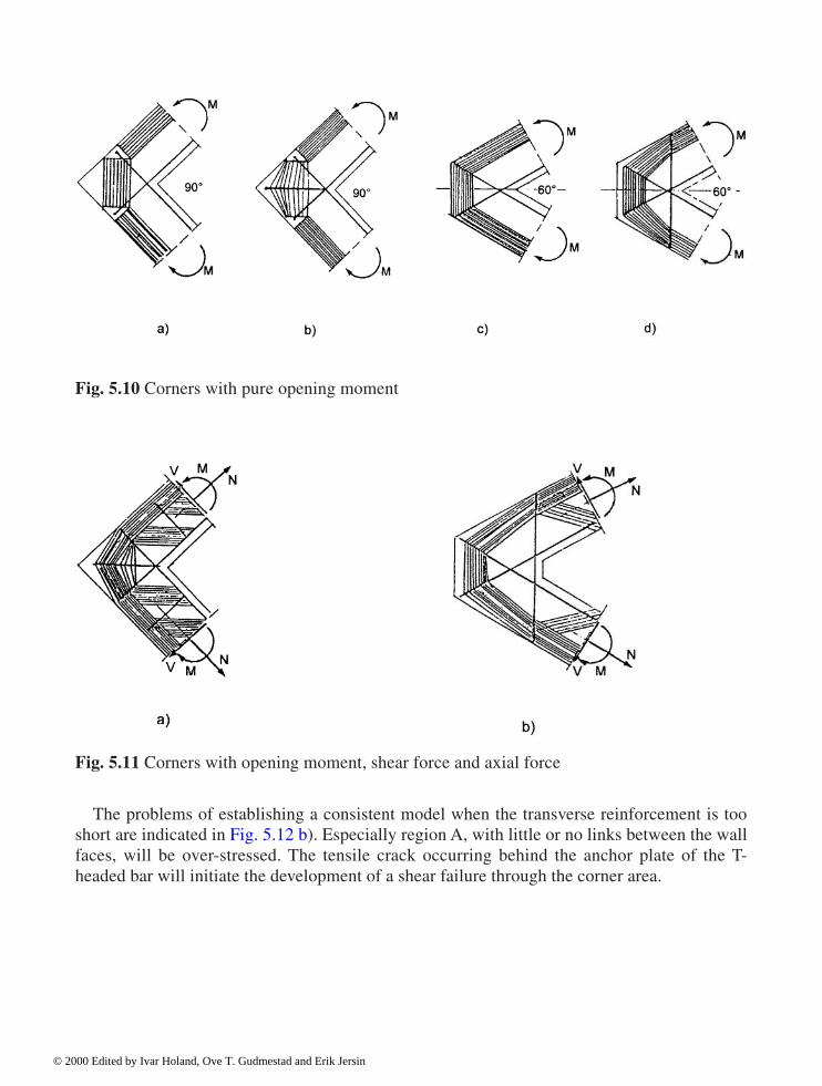
Design 147
Fig. 5.10 Corners with pure opening moment
The problems of establishing a consistent model when the transverse reinforcement is tooshort are indicated in Fig. 5.12 b). Especially region A, with little or no links between the wallfaces, will be over-stressed. The tensile crack occurring behind the anchor plate of the T-headed bar will initiate the development of a shear failure through the corner area.
Fig. 5.11 Corners with opening moment, shear force and axial force
© 2000 Edited by Ivar Holand, Ove T. Gudmestad and Erik Jersin

148 Design
Fig. 5.12 Force models for the tri-cell corner of Sleipner A1
© 2000 Edited by Ivar Holand, Ove T. Gudmestad and Erik Jersin
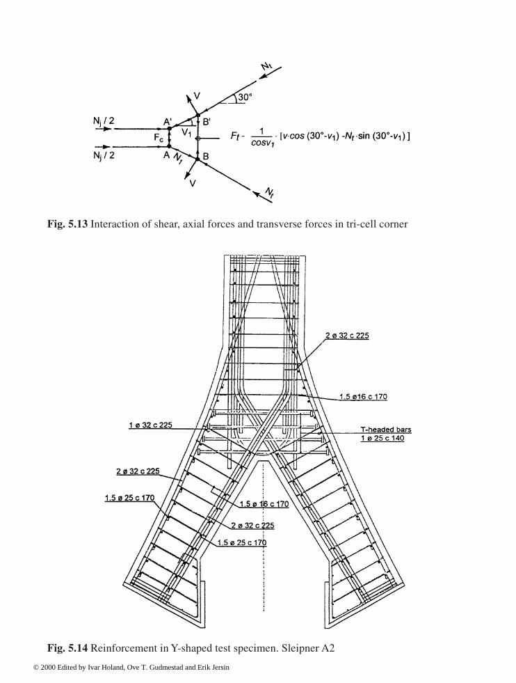
Design 149
Fig. 5.14 Reinforcement in Y-shaped test specimen. Sleipner A2
Fig. 5.13 Interaction of shear, axial forces and transverse forces in tri-cell corner
© 2000 Edited by Ivar Holand, Ove T. Gudmestad and Erik Jersin

150 Design
The necessary transverse reinforcement may be somewhat reduced by a further developmentof the force model in Fig. 5.12 a). The main question is to which extent the shear forces can becarried by a change of direction of the compression struts in the corner area. The interaction ofthe shear and normal forces in the corner is indicated in Fig. 5.13. When the normal forces arelarge, the transverse force (Ft) will decrease considerably by a small change of direction of thenormal force at point B.
The anchorage of the transverse reinforcement as close as possible to the opposite surface isa condition for the model to work as conceived. Tensile stresses in the concrete behind the endof the transverse reinforcement may initiate shear failure if the reinforcement is too short.Detailing of the transverse reinforcement with due consideration of practical placing of thereinforcement in slip-form construction is very important.
A series of small diameter bars with hooks around the outer horizontal reinforcement is probablythe best structural solution, but requires strict tolerances and many different reinforcement units.Large diameter transverse bars anchored by overlap parallel to outer layer horizontal reinforcementare possible, but difficult to place. Anchor plates in the form of right-angle T-heads will interferewith the concrete cover if anchored outside the outer layer of the longitudinal reinforcement asdesired. A combination of more than one type of reinforcement may be practical. Fig. 5.14 showsreinforcement detail sketch with T-headed bars combined with thinner hooked links.
The Y-shaped specimen shown was load-tested as part of the development of reinforcementdetails for the new Sleipner platform. The test proved satisfactory performance with a surpluscapacity without any sign of shear failure. The test confirmed that large tensile forces occur inthe corner, however; in the actual case the number of layers of T-bars probably could have beenreduced without significant change of the load bearing capacity.
5.3.5 Ship collision and falling objects
The design of concrete structures for ship collisions and impact from falling objects willmainly imply the design of walls and shells for various kinds of punching effects. Theprobability of occurrence of collision loads exceeding certain limits determines whether thedesign is performed according to the ultimate or accidental limit state criteria.
By ship collisions, the magnitude and distribution of a static equivalent load is mainlydetermined by the speed, mass and deformability of the colliding vessel itself. Impactmechanics and impact loads are dealt with in Chapter 3, Section 3.6.
As a rule the ordinary design formula for the resistance to local concentrated static loads(punching shear capacity) are applied. Shear reinforcement is often required in structures exposedto ship collisions between specified levels above and below the operational mean water level. Inthe case of collision with large ships, the global resistance of the structure will often be decisive.
Falling objects are usually regarded as stiff bodies with a specified kinetic energy hitting theconcrete structure at a concentrated contact surface. The impact of falling objects with highvelocity and small cross section may penetrate into the concrete and eventually lead to directperforation of the concrete shell structure.
The exposed upper domes of a Condeep structure or the pontoons of a floating concretestructure are often protected against moderate impacts from falling objects by a layer of low-strength lightweight aggregate concrete. In this case the load may be determined by the
© 2000 Edited by Ivar Holand, Ove T. Gudmestad and Erik Jersin

Design 151
dynamic crushing strength of the protective concrete, and the penetration depth by equating theimpact energy and the internal work. The resistance of the main structure is related to the staticpunching shear resistance with increased material strengths due to the high strain rates. Theexisting rules may not be fully applicable for extremely concentrated loads.
5.3.6 Fatigue
Fatigue of the longitudinal or shear reinforcement due to the large number of load cycles fromthe wave action may be decisive for certain parts of concrete platform structures. Fatigue ofconcrete in compression is seldom decisive.
Design rules concerning fatigue of reinforced and prestressed concrete are constantlydeveloping. Recommended references are CEB-FIP Model Code (CEB-FIP Model Code1990) and Norwegian Standard (NS3473, 1992). Safety against fatigue failure may bedifferentiated dependent on the basis of failure consequences and inspection accessibility. Anexample of safety differentiation is found in the regulations by the Norwegian PetroleumDirectorate (NPD, 1992), where the number of cycles during the assumed service life ismultiplied by a specified fatigue factor.
5.3.7 Prestressing
Several advantages can be achieved by the prestressing of structures. Prestressing may benecessary in certain parts of the structure to comply with specified requirements regardingwater-tightness or limitation of crack widths to avoid corrosion of the reinforcement.Prestressing is also applied to decrease the stress range in the ordinary reinforcement instructures subjected to fatigue-load cycles. Prestressed structures are to a larger extentperforming in the un-cracked state, with larger stiffness and better conformity between thelinear analysis and the design. The use of high strength prestressed reinforcement substitutinga larger amount of ordinary reinforcement will decrease the weight of the structure, which willbe advantageous in highly weight-sensitive floating structures.
On the other hand, prestressing of areas of the structure, which will be subjected to largecompression stresses by reversal of the direction of the load, might give undesirable additionalcompressive stresses.
The degree of prestressing of offshore structures is often presented as the percentage of theload effect of the characteristic wave action which is counteracted by the prestressing withouttensile stresses in the critical section.
The effect of prestressing is usually taken into account by a basic load case in the globalanalysis. The time dependent loss of prestress is taken into account by determination of anapproximate single loss factor for the actual part of the structure.
The needed prestressing force depends on the load effects. The optimal choice of degree ofprestressing is discussed and decided in each single case. The necessary prestressing is decidedmainly by the requirements regarding durability and water-tightness.
By the checking of maximum allowable crack widths to ensure durability without corrosion,it is usually accepted to calculate the load effects (normal force and moments) of waves
© 2000 Edited by Ivar Holand, Ove T. Gudmestad and Erik Jersin
152 Design
occurring 100 times during the service life of the structure. These load effects will be about75% of the effect of the characteristic wave with 100-year return period.
The usual water-tightness criterion for important buoyancy compartments is that resultingmembrane tension should be avoided in service state. An important question is for which waveload (return period) this requirement should be satisfied.
If the same load level as for the durability requirement is applied, there is a risk thatstructures designed for water-tightness may experience cracking through the full sections dueto seldom loads, but still with a high probability of occurrence during the service life of thestructure. Cracks through the section represent a weakness zone with potential water leakagealso after the closure of the crack.
Prestressing capable of resisting the axial forces due to the full characteristic (100-year)wave action without cracks through the section is recommended for structures where thetightness of the structure during the full service life is emphasized. It seems, however,reasonable to take into account a safe portion in the tensile strength of the concrete whendesigning for such rare wave loads.
The requirements in NS3473 regarding the maximum allowable stresses in the prestressingreinforcement may also influence the effectiveness of the prestressing.
In the section of NS3473 concerning the Serviceability Limit State it is stated:The stresses in the prestressed reinforcement shall for no combination of actionsexceed 0.8 fy, alternatively 0.8 f02.During prestressing, however, stresses up to 0.85 fy, alternatively 0.85 f02, maybe permitted provided it is documented that this does not harm the steel, and ifthe prestressing force is measured directly by accurate equipment.
The background for these requirements is mainly to prevent excessive loss of prestress in the
service state. This may occur if the steel is stressed significantly above the proportionality limitor exposed to such high sustained stresses that the relaxation of the steel increases considerably.
Because of the gradual decrease of the stresses in the prestressing steel with time due to thegeneral prestressing losses, the above requirements will usually be decisive duringprestressing. However, the stress in the prestressing steel may exceed the initial prestress inspecial cases with especially high service loads. This may be the case if the load effects of thefull characteristic 100-year wave are applied in the Serviceability Limit State. The requiredlimitation of the service stresses may then be decisive for the prestressing steel demand and thepossible choice of the prestressing level.
When designing for such seldom loads, it seems acceptable to allow stresses up to 0.85 fy,alternatively 0.85 f02 also in service states of short duration, provided that inelastic strain in theprestressing steel is compensated for by initial prestressing to the same level.
The passive anchors of the prestressing cables may be placed internally or at the surface of thestructure. The active prestressing anchor must be accessible from the outside and may be placed inrecesses or outside ribs. The use of recesses is the most practical method in slip-form construction.
The anchor recesses will disturb to some extent the flow of forces and the general reinforcementin the structure. The recesses are to be well distributed to avoid continuous weakness zones in thestructure. The recesses are grouted when the prestressing is finished, but the compression strengthof the grouted section is still somewhat reduced. The reduced compressive and tensile strengthloss is to be compensated by additional reinforcement if necessary.
© 2000 Edited by Ivar Holand, Ove T. Gudmestad and Erik Jersin

Design 153
It is important to calculate the tensile forces due to the deviation of the general forces aroundanchor zones and where the prestressing cables themselves change direction, and provide thenecessary reinforcement. Walls and shells are to be equipped with both transversal and extralongitudinal reinforcement in the anchorage zones.
5.4 Reinforcement
5.4.1 Basis for reinforcement design
All reinforcement is to comply with the requirements in relevant codes and the correspondingproduct standards. The required reinforcement amount calculated by the postprocessor andsupplementary manual calculations is the basis for the preparation of reinforcement drawingsand schedules.
The reinforcement systems used for offshore structures are principally the same as foronshore structures. The main practical differences from ordinary structures are the largedimensions and high loads, requiring particularly heavy reinforcement.
Furthermore, large parts of concrete platforms are slip-formed, e.g. skirts, cell walls andshafts. The comments concerning practical detailing and reinforcement systems in Section5.4.3 are therefore mainly related to slip-form construction.
The reinforcement production documents comprise reinforcement schedules, speciallistings of reinforcement for slip-form construction, “reinforcement keys” etc, in addition toordinary reinforcement drawings.
5.4.2 Minimum surface reinforcement
The primary purpose of the reinforcement is to transfer internal tensile forces. The commonlyused models for calculation of the capacity of concrete structures presuppose that the structureis sufficiently reinforced to establish a stable system of inner forces even after the tensilestrength of the concrete is exceeded and tensile cracks occur. The reinforcement must be ableto distribute cracks without yielding.
The reinforcement ratio necessary to meet this general requirement depends on the tensilestrength of the concrete and the distribution of the tensile stresses at cracking. The largestreinforcement percentage is required when the cracking is caused by axial tension.
According to NS3473 it is allowed to assess the necessary minimum reinforcement in eachactual case. Clause 17.4.1:
In each individual case, the actual structure and state of stress shall be takeninto consideration when determining the minimum reinforcement.
By this assessment of the crack distributing ability of the reinforcement it is to be taken intoconsideration that tension forces due to restraining of imposed deformations may influence thestate of stress significantly in minimum reinforced areas. Pure axial tension, however, occursmore rarely.
© 2000 Edited by Ivar Holand, Ove T. Gudmestad and Erik Jersin
154 Design
A reduced percentage of surface reinforcement may still give satisfactory crack distributionin thick structures. The main reason is that the tension forces transferred by reinforcementbonds introduce unevenly distributed tensile stresses in the concrete section.
The required minimum reinforcement is increased in areas of the structure exposed to highwater pressure. The reinforcement must resist the additional resultant of the water pressure atthe crack surface.
The minimum reinforcement in walls and shells according to the NPD-guidelines (NPD,1992) takes into account the thickness of the structure and the water pressure. The requiredminimum amount at each face and in each main direction is as follows:
As min
=k Ac (ft
k+av)f
tk/f
sk
where k is a factor varying from 0.4 for wall thickness 300 mm to 0.25 for wall thickness> 800 mm. (interpolation for intermediate wall thicknesses)v is the actual water pressure� is a factor, which is taken as 1.0 if the relevance of lower values is notdocumentedA
c is the area of the concrete section
ftk is the tensile strength of the concrete
fsk
is the yield strength of the reinforcement.
The theoretical k-value is 0.5 if the stress at cracking is constant through the thickness andftk is the actual tensile strength. Crack distribution is therefore not guaranteed by the requiredminimum reinforcement if this situation can occur.
Prestressed reinforcement in injected ducts only contributes slightly to the distribution of cracks.The general requirement regarding compressive reinforcement is not so clear. Standard
requirements have been related to general assessment of the safety of reinforced concretestructures. The increased safety of sections consisting of two materials with uncorrelatedstrength variables may be regarded as a condition for the use of material safety coefficients forreinforced concrete. The risk that tension may occur in unexpected directions, e.g. due toaccidental loads, is a further argument for requiring a minimum amount of reinforcement. Thedirection of the internal forces in shells and wall members of offshore structures subjected toenvironmental loads may vary considerably. Equal minimum reinforcement at both faces andin both main directions is therefore usually required.
5.4.3 Minimum transverse reinforcement
Simplification of the reinforcement by omitting transverse reinforcement is accepted inordinary thin slabs and walls in building structures. Slabs, as opposed to beams, may bedesigned without shear reinforcement if the shear capacity calculated according to thesimplified method is sufficient without stirrups.
This has also been good practice for ordinary shell structures. A minimum amount of shearreinforcement is required only when the shear reinforcement is assumed to contribute to theshear capacity of the shell. The usual requirement: As min=0.2 Ac ftk /fsk is identical to therequirement for slabs in NS3473. For concrete strength C75 and reinforcement yield strength
© 2000 Edited by Ivar Holand, Ove T. Gudmestad and Erik Jersin
Design 155
500 MPa this corresponds to, for example, Ø12 mm reinforcement links with spacing of 270mm in both main directions.
There are several special reasons for requiring a general minimum transversal reinforcementin walls and shells in large marine structures. Some of these reasons are: • Scale factors for thick structures• The use of concrete with high strength and brittleness• Water pressure in pores and cracks• Frequently lap sliced reinforcement• High bi-axial compression stresses. The use of a general minimum amount of transverse reinforcement is recommended in thickstructures exposed to high water pressure. Specific general requirements are lacking.
5.4.4 Reinforcement layout and detailing
The detailing of the reinforcement in structures composed of intersecting cells satisfying therequirements regarding the continuity and safe anchorage of the reinforcement and, at the sametime, the desired simplicity of production and placing of the reinforcement, is a challengingdesign task.
Based on the calculated theoretically necessary amount of reinforcement in a limitednumber of design points, a practical curtailment of the reinforcement is to be chosen whichsatisfies the required amount in all sections by a reasonably simple variation of thereinforcement in different sectors and levels.
The necessary extension of the reinforcement in order to cover the additional tension forcedue to the effect of transverse shear and the necessary anchorage length beyond the theoreticalpoints where a part of the reinforcement may be terminated, are to be considered by thecurtailment of the longitudinal reinforcement.
The curtailment of the transverse reinforcement is related to the distribution of the shear force.The recommended shear reinforcement curtailment for suspended loading is to be chosen wherethe shear force is due to water pressure, which may penetrate into cracks; see Fig. 5.7.
Continuity of the reinforcement with effective splicing and anchorage should beemphasized. However, due to the large dimensions of the structure and the rather shortpractical lengths of the reinforcement bars in slipform construction, the reinforcement will befrequently lap spliced throughout the whole structure, also in areas with high utilization of thecapacity. It is therefore utterly important to stagger the reinforcement and distribute the splicesas well as possible, preferably with not more that 1/3 of the reinforcement spliced in the samesection. The lap splices in the outer layers are to be secured by stirrups.
The reinforcement amounts are usually increasing towards the structural main nodes in theintersections between the structural members. Realistic models of the force flow in the nodeareas are necessary and helpful as a basis for the detailing of the reinforcement in such areas. Itis especially important to get a clear picture of which parts of the reinforcement should bemade continuous and which parts should be anchored and terminated in the node area. The
© 2000 Edited by Ivar Holand, Ove T. Gudmestad and Erik Jersin
156 Design
reinforcement is to be shaped in accordance with the analytical model and anchored safely atthe assumed local joints.
The general requirements concerning the local positioning of the reinforcement is stated inNS3473 as follows: • Reinforcement shall be placed in such a way that concreting will not be obstructed and so
that sufficient bond anchorage, corrosion protection and fire resistance will be achieved.• The positions of ribbed bars may be designed in accordance with the given minimum
spacings without regard to the ribs, but the actual outer dimensions shall be taken intoaccount when calculating clearance for placing of reinforcement and execution of theconcreting.
• The positioning of the reinforcement shall be designed so that the given requirements to theconcrete cover can be obtained in compliance with the specified tolerances.
The minimum theoretical clearance between single bars or bundles according to (NS 3473,1992) is 2 Ø
e (or 1.5 Ø
e in lap splicing areas), where Ø
e is the equivalent diameter of bundles.
Bundles are widely used in large structures, but more than 2 bars in each bundle (3 bars at thesplices) is avoided as far as possible.
It is important to take into account the actual outer dimensions of ribbed bars whenreinforcement in several layers is used. Production of realistic detail drawings (and sometimesprototype tests) of intersection regions is necessary to avoid obstructions during theconstruction work; (see Fig. 5.14).
Fig. 5.15 shows a simplified sketch of the reinforcement in a slipformed cell wall. Thereinforcement must be directed vertically and horizontally due to the yokes carrying theformwork and due to the continuous lifting operation. The horizontal “hoop” reinforcementmust be inserted beneath the yokes. The hoop reinforcement is preferably placed in the outerlayer outside the vertical reinforcement. The placing of more than one reinforcement layer oneach side of the curved wall is difficult. The second horizontal layer must in this case be placedinside the inner vertical layer, but handling of the curved bars in the internal of the wall is stilldifficult, and the practical bar lengths will be very limited. Reinforcement in several layers iseasier to accomplish in plane walls with straight bars.
The horizontal reinforcement is indicated on the drawings with the required constantspacing of the bundles. The required vertical reinforcement intensity is to be recalculated andindicated by the equivalent number of bundles between the yokes. The diameter of the shaftstructures will typically vary with the height levels. The distance between the yokes and thenumber of reinforcement bundles will vary accordingly.
The vertical reinforcement is placed inside guidance racks attached to the slipformconstruction. The vertical position and a reasonable distribution of the bundles are therebysecured. Vertical bars are placed as close as possible to the yokes to minimize the inevitableincreased spacing due to the width of the yokes (typically 200–250 mm). The designer musttake into account the necessary practical adjustment of the reinforcement in slipformconstruction by the choice of a reasonably large theoretical spacing in order to avoid violationof the minimum spacing requirement in practice. The spacing of the vertical bars can beadjusted (if needed) where the hoop reinforcement bars are tied to the vertical reinforcement.
© 2000 Edited by Ivar Holand, Ove T. Gudmestad and Erik Jersin

Design 157
Strict tolerances on the spacing of the vertical bundles are required at working joints. Thenecessary full co-ordination of the reinforcement in adjacent structural parts requires highquality production secured by operative quality assurance systems.
The concrete cover with its assumed tolerances is taken into account in the design. Thereinforcement is to be placed within the prescribed tolerances. “Spacers” are usually attachedto the top edge of the formwork to obtain the correct minimum cover of the outer layer of thehorizontal reinforcement, and thereby also securing the position of the outer layer of thevertical reinforcement. Additional spacers between the reinforcement layers are to beprescribed if more than one layer of vertical reinforcement is used.
By slipform production of structural members with varying dimensions it is important totake precautions to avoid the possibility that the reinforcement is forcing the formwork out ofthe correct position and direction. The opposite effect that the slipform is guiding thereinforcement, is the desired situation.
Simplification of the reinforcement with equal amounts in reasonably large sectors ispreferred in slipform construction. The continuous progress of concreting without delay is themandatory consideration.
The reinforcement system and detailing suggested by the designer should be discussed withthe responsible personnel at the building site before the finalizing of the reinforcement production
Fig. 5.15 Simplified reinforcement of slipformed wall
© 2000 Edited by Ivar Holand, Ove T. Gudmestad and Erik Jersin

158 Design
documents. This concerns primarily the personnel responsible for the reinforcement, but thepersonnel responsible for the concreting should also be consulted, especially when the density ofthe reinforcement will require special workability of the concrete. In that case it may also benecessary to determine the position of the concreting tubes in advance.
Thorough discussions with the responsible personnel at the site and adjustment of thereinforcement in order to simplify the execution, but without violation of the requiredcontinuity and safe anchorage of the reinforcement, will certainly result in more optimalreinforcement solutions. The staff on site has generally the best knowledge of the problemsoccurring during the execution of the reinforcement. Some of the points of importanceregarding the mounting of the reinforcement are: • Practical lengths and shapes of the reinforcement (handling weight limits, simplicity of
production and installation)• The number of regions with different reinforcement (a large number of variants will
generally increase the risk of errors and delay)• Practical and clear production documents (drawings, lists, etc). It is often necessary to increase the number of workers drastically within the limited timeperiods when the large main parts of the structures are reinforced and concreted. This isespecially the case when executing large slipform constructions on continuous shift-workbasis. In addition to the proper training of all personnel on site, the best guarantee for asuccessful result is the choice of a simple reinforcement without unnecessary large number ofreinforcement variants.
Reinforcement shapes or amounts are not to be changed on site without the explicit approvalby the responsible designer. All changes are to be reported, registered and evaluated. Thechanges are finally summarized in updated drawings showing the final structure as built.
References
Bjerkeli, L.M. (1990) Water Pressure on Concrete Structures. Dr.ing Thesis 1990:31, Divisionof Concrete Structures, The Norwegian Institute of Technology.
Brekke, D.-E., Åldstedt, E. and Grosch, H. (1994) Design of Offshore Concrete StructuresBased on Postprocessing of Results from Finite Element Analysis (FEA): Methods,Limitations and Accuracy. Proceedings of the Fourth International Offshore and PolarConference, ISOPE, Osaka, Japan, pp. 318–28.
CEB-FIP. Model Code 1990 (1993). Thomas Telford Services, London
CEN (Comité Européen du Normalisation) (1991) European Prestandard ENV 1992–1–1.Eurocode 2. Design of concrete structures .
Collins, M.P. and Mitchell, D. (1991) Prestressed Concrete Structures. Prentice-Hall.
© 2000 Edited by Ivar Holand, Ove T. Gudmestad and Erik Jersin

Design 159
ISO standard 13819 Part 3 (to appear, will cover the entire engineering process for offshoreconcrete structures).
Jakobsen, B., Gausel, E., Stemland, H. and Tomaszewicz, A., (1993) Large-scale tests on cellwall joints of a concrete base structure. High Strength Concrete 1993 Proceedings.Lillehammer, Norway.
Norwegian Council for Building Standardisation, NBR (1998), Norwegian Standard NS 3473Concrete Structures, Design rules, 4th edition, Oslo, Norway, 1992 (in English), 5th edition1998 (English edition in print).
Norwegian Council for Building Standardisation (NBR) (1990) Norwegian Standard NS 3479Design of Structures. Design Loads. 3rd Edition (In Norwegian).
Norwegian Petroleum Directorate (NPD) (1992) Regulations Concerning LoadbearingStructures in the Petroleum Activities. Including guidelines for structural design of concretestructures, stipulated by NPD, Stavanger, Norway.
Statoil (1992) N-SD-001. Specification for Design. Structural Design for OffshoreInstallations.
© 2000 Edited by Ivar Holand, Ove T. Gudmestad and Erik Jersin

6 Quality assurance
Erik Jersin, SINTEF
6.1 Introduction
6.1.1 Purpose and limitations of Chapter 6
The purpose of this chapter is to give a general view of the basic demands for QualityAssurance and throw light on what these imply when it comes to engineering, design anddimensioning of concrete structures at sea.
The description particularly concentrates on important elements, considering the scope of thisbook. Consequently, this chapter does not give a complete picture of which requirements shouldbe fulfilled, for instance to fully satisfy ISO 9001:1994 Quality Systems. Model for qualityassurance in design, development, production, installation and servicing. Thus, among othersthe following important elements in ISO 9001:1994 have only been dealt with superficially:
4.1 Management responsibility4.5 Document and data control4.13 Control of non-conforming products4.14 Corrective and preventive action4.16 Control of quality records
In addition, Quality Assurance related to the development and use of software has not beendealt with here. Particular standards for the above-mentioned exist, e.g. ISO 9000–3:1992Quality Management and Quality Assurance standards, Part 3: Guidelines for the applicationof ISO 9001 in development, supply and maintenance of software.
6.1.2 Special features of engineering and design of concrete structures at sea
In relation to Quality Assurance there are several conditions that characterize engineering anddesign of concrete structures (Gravity Base Structures—GBS) at sea: • Improved calculation models and larger computer capacity has led to more reliable
calculations and better utilisation of loadbearing structures than previously. Consequently,reduced safety factors have been accepted. However, attention should be drawn to the factthat the introduction of higher and more complex technology, generally speaking, doesincrease the vulnerability to errors, faults and other nonconformities. Thus, to maintain thesame level of safety even better conformance to specifications during engineering, design,dimensioning and construction is required.
© 2000 Edited by Ivar Holand, Ove T. Gudmestad and Erik Jersin
162 Quality assurance
• The use of rather complicated computer systems for analysis, calculation and dimensioningimplies a certain risk of reduced awareness of the importance of keeping a general view onthe construction.
• Short time limits often make it necessary to carry out simultaneously, activities thatpreviously were carried out in series. Concurrent engineering thus leads to a number ofiterations and greater demand for managing the changes.
• A considerable number of certain types of GBS’s, e.g. Condeep, have been built. Thus there is adanger of reduced attention during the engineering, design and construction processes. When atask or a project comes to be looked upon as a routine job, it is tempting to use younger personnelwith less experience. However, if one does not make sure that senior personnel with sufficientexperience attend to the control functions, there is a serious risk of jeopardising the quality.
• After the Internal Control and Quality Management/Quality Assurance concepts were broughtinto focus during the last decade, there has been a shift in attention from the product (the structure)to the processes and procedures that generate the product. The strategy behind this is clear andlogical enough. In general, it will be wise to focus on the prevention of mistakes, deviations andnonconformities as opposed to inspection and rework at later stages. Thus, by focusing on theorganizing, planning, procedures and management systems instead of employing extensivechecks of details in the final product, greater profit can be achieved. However, the question couldbe raised, whether this trend has gone too far during the last decade. Thus, a present challengecould be to find the right balance between (system) control and (product) inspection.
6.1.3 Vocabulary
In the discussion of Quality Assurance in this chapter, the latest version of ISO’s vocabularystandard in this field has been used (ISO 8402:1994 Quality Management and QualityAssurance. Vocabulary).
In general, it should be noted that in everyday speech one would often come acrossparticular, usually trade-related terms. These could have occurred more or less by chance, andcan be a mixture of different languages, e.g. Norwegian, English and American. Such termsshould not be used uncritically, because they often lead to confusion rather than improvedcommunication. Two examples are given below.
Design Review is a well-established term in most trades and commonly used in QualityAssurance standards. Within some companies, the term Engineering Technical Audit is oftenused, as well. The content of this term in fact is so similar to Design Review that the need for itcould be questioned. Problems that may be experienced in making the Design Reviewseffective are hardly solved simply by introducing another term.
Likewise, Quality Audit is another well-established term. The term Implementation Reviewis sometimes used to denote a Quality Audit carried out prior to Contract Award. The rightterm would be, for example, Pre Contract Quality System Audit.
Moreover, one should be aware of the fact that the ISO vocabulary is being revised fromtime to time. In addition, new standards and guides are more or less continuously being drawnup. A need for defining new terms or re-defining previously used terms may arise. Because itusually takes several years to revise an existing ISO-standard and even longer to publish a newone, terminology in itself can be a problem.
© 2000 Edited by Ivar Holand, Ove T. Gudmestad and Erik Jersin

Quality assurance 163
The conclusion is that it would be wise to follow the ISO 8402 strictly, avoid self-inventedterms, if possible, and by all means define necessary additional terms carefully.
6.1.4 Further reading
The following textbooks could be recommended for more detailed information:
Carrubba, E.R. and Gordon, R.D. Product Assurance Principles. Integrating DesignAssurance and Quality Assurance. McGraw-Hilll Book Company, New York, 1988. ISBN0-07-010148-5.
Evans, James R. and Lindsay, William M. The management and Control of Quality. WestPublishing Company, St. Paul, 1989. ISBN 0-314-47285-1.
Fox, M.J. A Quality Auditing Manual. Technical Communications (Publishing) Ltd.,Letchworth, 1992. ISBN 0-946655-62-6.
Jersin, Erik. Kvalitetsstyring—Kvalitetssikring—Kvalitetskontroll. TAPIR, Trondheim, 1985.(In Norwegian only.) ISBN 82-519-0596-6.
Juran, J.M. Quality Control Handbook. McGraw-Hill, New York, 1988, ISBN 0-07-033176-6.
Lock, Dennis (ed.). Handbook of Quality Management. Grower Publishing Company Limited,Hants, 1990. ISBN 0-566-02770-4.
Onnias, Athuro. The Language of Total Quality. TPOK Publications on Quality. Castellamonte(To), 1992. ISBN 88-86073-00-3.
Robinson, Charles B. How To Make The Most Of Every Audit: An Etiquette Handbook ForAuditing. ASQC Quality Press, Milwaukee, 1992. ISBN 0-87389-158-9.
Rothery, Brian. ISO 14 000 and ISO 9000. Gower Publishing Company, The Netherlands,1995. ISBN 0-566-0764-89.
6.2 Basic requirements for quality assurance
6.2.1 Reference requirements
The basic Quality Assurance requirements that regulate the activities of offshore operators andcontractors at the Norwegian continental shelf have been laid down in the followingdocuments: • ISO 9001:1994 Quality Systems. Model for quality assurance in design, development,
production, installation and servicing.• The Petroleum Act and corresponding regulations, particularly The Norwegian Petroleum
Directorate (NPD): Regulations concerning the licensee’s internal control in petroleum
© 2000 Edited by Ivar Holand, Ove T. Gudmestad and Erik Jersin

164 Quality assurance
activities on the Norwegian Continental Shelf with comments (“The Internal ControlRegulation”)
In addition, several guides are in frequent use. These are not regulatory documents, but offerguidelines. Particular attention should be drawn to the following: • ISO 9004–1:1994 Quality management and quality system elements. Part 1: Guidelines.• ISO 9000–3:1992 Quality management and quality assurance standards. Part 3: Guidelines
for the application of ISO 9001 to the development, supply and maintenance of software.• ISO 10011:1992 Guidelines for auditing quality systems. Parts 1, 2 and 3.• ISO 9004–4:1995 Quality management and quality system elements. Part 4: Guidelines for
quality improvement. Note that “The ISO 9000-family” is being revised at present. The target dates for publishingthe revised standards are year 2000–2001. However, there is no reason to assume that theactual quality assurance requirements in the revised standards will be significantly changed.
6.2.2 The three basic principles of Quality Assurance
In view of the large number of documents that exist when it comes to Quality Management(QM) and Quality Assurance (QA), it is important to keep in mind the following three simpleand basic QA principles: • Prevent• Detect• Correct These principles in fact form the three-pronged basic strategy of all commonly used QAstandards and guidelines to day. Table 6.1 gives a broad outline of how the most usual QualityAssurance requirements can be grouped accordingly.Each element is described in more detail below.
Table 6.1. The basic principles of Quality Assurance and some corresponding requirements
© 2000 Edited by Ivar Holand, Ove T. Gudmestad and Erik Jersin

Quality assurance 165
(a) PreventIn modern Quality Assurance, the main consideration is to prevent defects and non-conformities from occurring in the first place. This is because it would always be profitable todo things “right the first time”, as opposed to correcting mistakes and nonconformities lateron. In addition, prevention increases the chances of the final product being correct, since thereis always a risk that inherent defects and nonconformities will not be detected at all, or notuntil it is too late. Note that the term “product” may include service, hardware, processedmaterials, software or a combination thereof (ISO 8402). In this chapter, “product” alsoincludes intermediate results of the engineering, design and construction process, i.e.calculations, drawings, specifications and other documents.
The most important preventive activity during engineering and design, in addition to goodorganizing and planning, is to make sure that the key personnel working on the project havesufficient and suitable competence (knowledge and experience). (b) DetectIn general, it should be appreciated that modern technology and the interaction betweentechnology and man, is not well enough developed to prevent all defects and nonconformitiesfrom occurring. Man is often considered to be the weakest joint in the chain. This goes for manyproducts and businesses. It is therefore important to realise that defects and nonconformitiescertainly will occur from time to time, almost regardless of how much effort is put into preventingthem.1 Efficient checks, inspections, audits and reviews must therefore be organized to ensurethat the nonconformities are discovered and as quickly as possible, before they lead to seriousconsequences in terms of quality or safety problems, or financial losses.
During engineering, design and dimensioning, such checks should be carried out at differenttimes and by means of various techniques. As mentioned above, the checks would have twoobjectives. One is to verify the processes, i.e. that the quality control and quality assurancesystems are effectively planned and implemented. To this end Quality (System) Audits shouldbe carried out. The other objective is to check the output, i.e. the results of the differentactivities during engineering, design and dimensioning. To this end Self-Checks, DisciplineChecks (DC), Inter Discipline Checks (IDC) and Third Party Verifications are vital. (c) CorrectAs soon as a nonconformity has been detected, it must be assessed and a decision about how itshould be treated further must be made. It is important that the decision is made at the rightlevel in the organization. “Right level” here usually means the lowest level that has a completeview of the consequences of the decision. Usually, the decision concerning nonconformity inthe engineering and design phase will be to correct or revise the relevant documents,calculations, etc. to satisfy the requirements. However, sometimes it may be relevant to applyfor a deviation permit, with or without rework. This would often imply a need for approval bythe authorities. In any case, the procedure for treatment of nonconformities should be welldefined beforehand. To ensure verifiability and possibility of supervision of nonconformities,the decisions must be properly recorded as well.
Having treated the nonconformity in a justifiable manner, it is important to analyse why it
1 The nuclear, space and aviation industries put down more efforts and resources to prevent failures than any other trade. Still, seriousaccidents do occur and unfortunately will continue to occur from time to time in the future.
© 2000 Edited by Ivar Holand, Ove T. Gudmestad and Erik Jersin
166 Quality assurance
occurred, i.e. to find the root cause, and implement the necessary measures to preventrecurrences. Such measures are usually called Corrective Actions. The analysis also includesan evaluation of the present nonconformity in view of previous ones, in order to discover andcorrect prospective unfortunate trends as early as possible. If, for example, a significantlyincreasing number of defects have been detected on drawings after they have been distributed,this could be a reason for tightening up the Self-Check requirement on the designers.Alternatively, the drawing software programs should be re-checked (verified).
6.3 Quality assurance in engineering and design of concrete structures
6.3.1 The ISO requirements for Quality Assurance
ISO 9001 describes a series of general requirements to the quality system in engineering anddesign, construction, installation and servicing. In this chapter we presuppose that such a basicsystem has been implemented. This means that the ISO requirements regarding determinationof Quality Policy, responsibility and authority, etc. are fulfilled and in addition that proceduresexist for document control, nonconformity treatment, corrective actions, quality records,internal quality audits, training, etc. In this chapter, we will therefore concentrate on thoseelements that are particularly relevant in engineering and design of concrete structures.
The general requirements for Quality Assurance in engineering and design are described inthe following ISO standards: • ISO 9001:1994, item 4.4• ISO 9004–1:1994, item 82. In general, the ISO 8402:1994 terms have been used. In the cases where these deviate from theterms that are used among concrete professionals, the latter have been used.
6.3.2 Some important QA-elements and QA-tools in engineering and design
“QA-elements” in this context means the procedures, etc. that are required for the Quality Systemto satisfy the 20 main requirements in the ISO 9001:1994 standard. These elements have beengiven the numbers 4.1 to 4.20 in the standard. “QA-tools” are used as a less precise term forcertain specific techniques and tools that will contribute to fulfilling the requirements effectively.
Some of those elements and tools have been described in brief below, namely qualifying keypersonnel, Self-Check, Discipline Check (DC), Inter Discipline Check (IDC), Third PartyVerification, Design Review (DR), Hazard and Operability Studies (HAZOP), Worst-CaseAnalysis and Quality Audit.
Fuller descriptions are given in Appendices B-H.
2Note that ISO 9004–1 is a Guide; it is not intended as a contract requirement.
© 2000 Edited by Ivar Holand, Ove T. Gudmestad and Erik Jersin

Quality assurance 167
(a) Qualifying key personnelIn design of concrete structures, as in other high technology projects, one of the most importantpreventive measures is ensuring that fully qualified personnel are assigned to the key positions.Before anyone is appointed, it should be made clear which basic qualifications and what type ofexperience, for example from similar projects, are required. Subsequently, the most suitablecandidates should be selected based on CVs, references and interviews. Finally, the candidatesshould be asked to outline how they will attack the task, and the answers evaluated. (b) Self-CheckAll analyses, calculations and documents should be thoroughly self-checked, that is to saychecked by the person or persons who have carried out the work, before the results are passedon to others. As mentioned, the policy should be to make everything right the first time.
Fig. 6.1 shows the relation between Self-Checks and the other elements in the verificationprocess.3 When Fig. 6.1 is read vertically, the order of the different checks appears. Thus, alldocuments and drawings should first be subject to a Self-Check, i.e. a check by the same personwho is carrying out the task. If a nonconformity (NC) to the specification for that particular taskis observed it should be corrected at once, i.e. before the document or drawing is passed on. Therelevance of the subsequent checks depends on the criticality of the document or drawing. If thetask has no criticality classification at all, the result would pass on to a Design Review (if required)or directly for approval. If classified I, II or III (see Table 6.2) the document or drawing would besubject to a Discipline Check at a suitable level. Documents or drawings of Criticality II and IIIwould in addition be subject to an Inter Discipline Check (if relevant). The most critical results(Criticality III) would finally be subject to a Third Party Verification as well.
If nonconformity is detected during these checks, the document or drawing will, of course,have to be corrected or re-worked. In Fig. 6.1 this is indicated by the dotted feed-back loops.
Design Review, Discipline Check, Inter Discipline Check and Third Party Verification aremore closely examined below and in Appendices B—E. (c) CriticalityThe amount or level of quality assurance of documents and drawings should reflect their importance(level of criticality), which could be decided by a qualified person or by a Design Review. Thecriticality should be clearly stated in the document. This is to ensure that the level of attentioncoincides with the document’s importance in relation to quality, safety, environment and/oreconomy. Three levels of criticality are described in Table 6.2. In engineering and design ofGravity Base Structures (GBS’s) a major part of the technical calculations, documents and drawingswill in principle be of Criticality III. However, as indicated in Fig. 6.1, there are still severalpossibilities for tailoring the amount of quality control to a suitable level. (d) Discipline check (DC)A Discipline Check is an inspection to ensure that the technical documentation satisfies allinternal and external requirements within one’s own discipline before further distribution anduse. In order to be acceptable, a Discipline Check has to be independent, i.e. carried out by acompetent person or body other than the one(s) that drew up the documents, or wereresponsible for or involved in the process in some other way. This goes for the other types of
3 The term verification is used here as a joint term for several types of checks that aim at providing evidence that specified requirements hasbeen fulfilled.
© 2000 Edited by Ivar Holand, Ove T. Gudmestad and Erik Jersin

168 Quality assurance
verification as well, except for Self-Check. However, as mentioned above, the necessary levelof independence may vary according to the criticality of the document or drawing.
The reason for the principle of independent checks is that, according to many years of experience,it is usually much easier to discover mistakes, defects and weaknesses when it comes to other’swork than one’s own. In addition, those who carry out the checks should not be under any influenceor pressure that could have a negative impact on quality. Such a pressure would, for example,exist if the person(s) carrying out the checks would also be held responsible for lost time oradditional costs resulting from detecting and correcting errors. Discipline Check (as well asThird Party Verification; see Fig. 6.1) can be carried out on four different levels:Level 1: Document ReviewLevel 2: Extended Document ReviewLevel 3: Independent CalculationLevel 4: Scale TestFor a further description of Discipline Check, as well as the four above-mentioned levels, seeAppendix B and Chapter 7, Verification of design.
Fig. 6.1. The verification process in engineering and design
© 2000 Edited by Ivar Holand, Ove T. Gudmestad and Erik Jersin
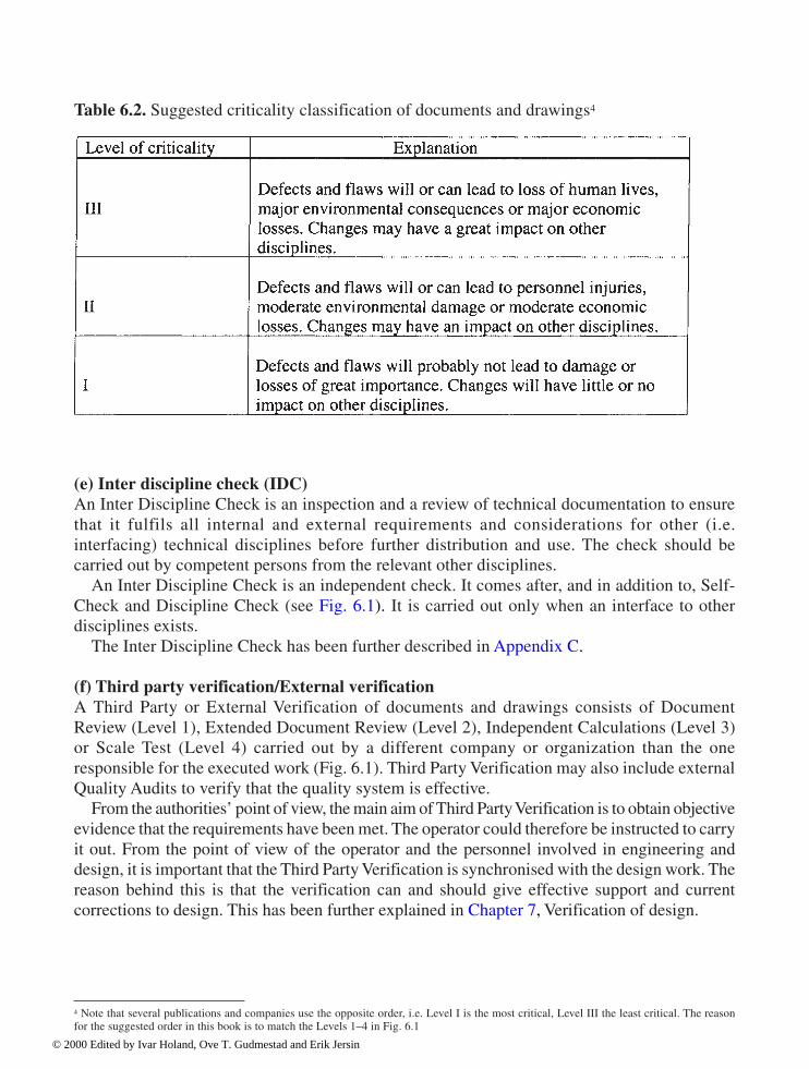
Quality assurance 169
(e) Inter discipline check (IDC)An Inter Discipline Check is an inspection and a review of technical documentation to ensurethat it fulfils all internal and external requirements and considerations for other (i.e.interfacing) technical disciplines before further distribution and use. The check should becarried out by competent persons from the relevant other disciplines.
An Inter Discipline Check is an independent check. It comes after, and in addition to, Self-Check and Discipline Check (see Fig. 6.1). It is carried out only when an interface to otherdisciplines exists.
The Inter Discipline Check has been further described in Appendix C. (f) Third party verification/External verificationA Third Party or External Verification of documents and drawings consists of DocumentReview (Level 1), Extended Document Review (Level 2), Independent Calculations (Level 3)or Scale Test (Level 4) carried out by a different company or organization than the oneresponsible for the executed work (Fig. 6.1). Third Party Verification may also include externalQuality Audits to verify that the quality system is effective.
From the authorities’ point of view, the main aim of Third Party Verification is to obtain objectiveevidence that the requirements have been met. The operator could therefore be instructed to carryit out. From the point of view of the operator and the personnel involved in engineering anddesign, it is important that the Third Party Verification is synchronised with the design work. Thereason behind this is that the verification can and should give effective support and currentcorrections to design. This has been further explained in Chapter 7, Verification of design.
4 Note that several publications and companies use the opposite order, i.e. Level I is the most critical, Level III the least critical. The reasonfor the suggested order in this book is to match the Levels 1–4 in Fig. 6.1
Table 6.2. Suggested criticality classification of documents and drawings4
© 2000 Edited by Ivar Holand, Ove T. Gudmestad and Erik Jersin

170 Quality assurance
Third Party Verification can be costly and should therefore only be used to identify andverify the most critical parts of the structure (Criticality III, see Table 6.2). For furtherdescription, also see Appendix D. (g) Design review (DR)Briefly explained, a Design Review is a systematic, independent review of the design and theway it is documented. In general, Design Reviews should at least be carried out between themain activities or phases of the project (see Fig. 6.2). The general aim is to optimalize thedesign solutions. The reviews should be carried out by groups of persons who have the relevanttechnical background and experience, among other things, in order to obtain synergetic effectsand make the most of the available competence.
For further description of Design Review, see Appendix E. (h) Hazard and operability studies—HAZOPA HAZOP is a formal, systematic and critical review of different parts of a system, design,plant or structure in order to identify potential problems regarding safety and operability, sothat risk-reducing actions can be implemented. The analysis could be a complete risk analysisor a pre-study for more detailed studies of critical parts of a structure. HAZOP can be carriedout both during pre-engineering and detail design. The analyses could also be carried outduring operations, e.g. in connection with maintenance or modifications of the design or theoperational procedures. For further description, see Appendix F. (i) Worst-case analysisA Worst-case analysis is a systematic analysis and evaluation of the consequence of the worstpossible input data, occurrences and combinations of occurrences, to personnel, theenvironment and assets.
The purposes of a Worst-Case Analysis are two-sided (for further description, see Appendix G): • To verify that safety and other important functions are maintained under abnormal loads,
foreseeable abuse and abnormal human stress.• To ensure that decisions on not designing and dimensioning for such extreme conditions
are made on the right (i.e. high enough) level in the organization. (j) Quality audit/Quality system auditA Quality (System) Audit is, simply put, a systematic and independent review or investigationto ensure that the Quality System is properly designed and implemented. Audits should becarried out according to written procedures.
Quality Audits have been greatly emphasised as an important management tool during thelast decades. Requirements have been made to ensure that the audits are carried out both inNPD’s Internal Regulations and in ISO 9001. However, it can be argued that practice withinthis area has developed in a somewhat unfortunate direction. Especially within offshoreapplications, attention has been drawn primarily to audits of written quality systemdescriptions and procedures. The question could be raised, whether this may have been at thesacrifice of attention on the quality of the actual product.
For further description of Quality Audits, see Appendix H.
© 2000 Edited by Ivar Holand, Ove T. Gudmestad and Erik Jersin

Quality assurance 171
6.3.3 Quality Assurance elements related to the main activities in engineering anddesign
Fig. 6.2 gives a general view of the main activities and documents in the engineering anddesign phase.
The first activity is Review and detailing of Design Basis (Fig. 6.2). This is done on the basisof the Concept Report from the previous phase (Concept Defining). The Concept Reportcontains the superior Design Basis with separate chapters regarding loads, environmental data,functional requirements, conditions for use, geotechnical conditions and reference documents.During this stage, a further analysis of the conditions for the structure, and an in-depth reviewof the consequences for the different disciplines, are carried out.
A general requirement to the results of all the activities during design, is that the documentsmust be correct and attend to all necessary regards to clarity, unambiguity and suitability forfurther use, including traceability and verifiability. This means that the configuration controland the document control must be satisfactory, as well. In relation to this, one should alsorealise that the iterative character of the engineering and design process makes it veryimportant to be in total control of all changes that are made on the way. “Total control” heremeans that all consequences of the proposed changes should be considered thoroughly and
Fig. 6.2 Main activities and documents in engineering and design of marine concretestructures (DR=Design Review).
© 2000 Edited by Ivar Holand, Ove T. Gudmestad and Erik Jersin

172 Quality assurance
evaluated at the right organizational level before they are implemented. This implies amongother things that the person(s), who worked out the original requirement or the previoussolution, should have an opportunity to assess the consequences of the proposed changes,before they are accepted and implemented.
When a change has been accepted, everyone who is in position of the original documentsmust be informed of the change at once.
During the review and detailing of the Design Basis for the different disciplines, Self-Checks, Discipline Checks, and Inter Discipline Checks should be carried out. This isindicated with small parallelograms in Fig. 6.2.
A (Project) Quality Plan should be prepared at the same time as the review and detailing ofthe Design Basis (see Fig. 6.2). The Quality Plan describes the particular quality assuranceactivities that are to be carried out in the project to satisfy the requirements, and what resourcesshould be used for this. Table 6.3 gives an example of the layout of a Quality Plan for theengineering and design phase.
The Quality Plan should be rooted in the operator’s Quality System and be co-ordinatedwith or constitute part of the Project Plan. The Quality Plan for the complete project shouldinclude the following elements as well (ref.: ISO 9004–1:1994, item 5.3.3 and ISO 9004–5Guidelines for quality plans): • Description of aims for quality• Distribution of responsibility and authority in different project phases• Procedures, methods and work instructions that are to be employed
Table 6.3. General layout of a Quality Plan during engineering and design (example)
© 2000 Edited by Ivar Holand, Ove T. Gudmestad and Erik Jersin

Quality assurance 173
• Programs for testing, reviews, inspections and audits in the different phases• System for change and modification of the Quality Plan as the project proceeds• Other initiatives that are to be carried out in order to reach the goals.
The Design Brief (see Fig. 6.2) is prepared on the basis of the revised Design Basis. TheDesign Brief lays down the Design Criteria further, together with the design procedures,important interfaces and preferred methods for analysis and calculations. Other important partsare the results of criticality evaluations for the individual parts of the structure, and aspecification of the software programs accepted for use.
During development of the Design Brief, the same quality elements as in the treatment ofthe Design Basis should be employed, that means Self-Check, Discipline Check, InterDiscipline Check and Design Review. Since the extent of the documents is steadily increasingas the project progresses, it is evident that the checks require more and more resources. Tosome extent, different kinds of competence are needed, too.
The analyses are carried out on the basis of the Design Brief. They consist of DynamicWave Analysis, Stability Analysis and Global Analysis.
Dynamic Wave Analysis results in dimensioning waves for different parts of the structure,hydrodynamic loads, masses and damping. The results are used as basis for the GlobalAnalysis.
Stability Analysis gives an answer to whether the structure has the necessary stability againstcapsizing during the construction process, submerging, tow-out, installation, operation andservice. Both floating stability and geotechnical stability has to be assessed.
Global Analysis gives an answer to what kind of strain the different parts of the structure isexposed to during submerging, tow-out, installation and operation.
The three above-mentioned analyses together make up the basis for the later dimensioning,and are therefore critical for the structure’s safety and fitness for use. Related to Figs. 6.1 and6.2, there is a need for a more comprehensive quality assurance than previously, in this phaseof the project. In addition to Self-Check, Discipline Check and possibly Inter DisciplineCheck, Third Party Verifications would therefore be needed and hence required by theauthorities.
The dimensioning is carried out on the basis of a general view of the load effects. Duringdimensioning, the length and location of the reinforcement, the final wall thickness and thequality of the concrete and the reinforcement are determined.
The result of the dimensioning is entered in the Dimensioning Document. This should besubject to Self-Check, Discipline Check and possibly Design Review before the drawing workstarts.
The drawing work will result in drawings, material lists and descriptions that are necessaryfor the construction to start (see Fig. 6.2). All sketches and specifications should be subject toSelf-Check and suitable independent verification. A Design Review (“Engineering ReadinessReview”) should be completed before release for construction and fabrication.
© 2000 Edited by Ivar Holand, Ove T. Gudmestad and Erik Jersin

7 Verification of design
Tore H.Søreide, Reinertsen Engineering
7.1 Introduction
The purpose of this description of verification is to present a procedure for control for detaileddesign of offshore structures. For exemplification, Chapter 7 refers to government regulationsfrom the Norwegian Petroleum Directorate (NPD, 1997) as well as company specificationsfrom the Norwegian oil company Statoil (Statoil, 1991). Both documents require designverification to be part of the quality assurance. The major activities of verification are outlinedbelow, together with the basis for verification in the form of authority and companyspecifications.
Chapter 6 has presented the overall system for quality assurance, where design verificationis an integrated part. The objective of verification is to guarantee that the final product is inaccordance with the Government regulations and Company specifications. For engineering,the outcome is in the form of drawings and specifications for fabrication.
The NPD regulations (NPD, 1997) give detailed requirements concerning verification.Section 7.2 discusses these requirements as well as the corresponding verification activities.Depending on their importance for the quality and safety of the final structure, the variousdocuments need different types of control. Section 7.3 presents four levels of verification thatinvolve document control as well as prototype testing.
Section 7.4 considers a system for external verification. Special emphasis is given to theview that the verification should ideally also be a support for engineering, so that timecoordination becomes important. Alternative means of organizing verification are presented inSection 7.5, while Section 7.6 considers administrative services coupled to the work onverification. These services include budgeting and a set-up for reporting and communicationbetween the engineering and verification bodies on unsolved topics.
Qualification requirements for the engineers participating in the verification work are dealtwith in Section 7.7. Special effort should be made to guarantee that there are particularlycompetent people in the technical lead position within the verification activity. An essentialfunction of the technical leader is to sort out the major technical questions for follow-up.Section 7.8 exemplifies the scope of work involved and how the verification job may beplanned. Fig. 7.1 illustrates the importance of co-ordination in time between engineering andverification. It is clear that for the verification to affect design prior to fabrication, thecomments from verification should reach engineering within the timeframe when the problemis being addressed. If not, it is often difficult for engineering to react to the comments fromverification, and a negative atmosphere of dialogue arises.
© 2000 Edited by Ivar Holand, Ove T. Gudmestad and Erik Jersin
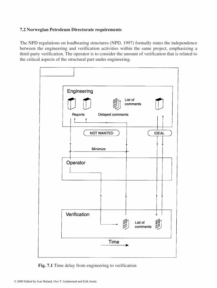
176 Verification of design
7.2 Norwegian Petroleum Directorate requirements
The NPD regulations on loadbearing structures (NPD, 1997) formally states the independencebetween the engineering and verification activities within the same project, emphasizing athird-party verification. The operator is to consider the amount of verification that is related tothe critical aspects of the structural part under engineering.
Fig. 7.1 Time delay from engineering to verification
© 2000 Edited by Ivar Holand, Ove T. Gudmestad and Erik Jersin

Verification of design 177
NPD provides a detailed list of verification activities. These are areas of verification that all engi-neering on offshore loadbearing structures should undergo. Among the essential areas listed are: • Design Basis in accordance with guidelines• Qualifications by personnel in engineering• Organization of engineering• Documentation and testing of computer programs• Load modelling• Response analysis• Capacity control• Tolerances in design• Drawings in accordance with design calculations• Design and forming of details. For parts of the structure that are essential for its integrity, verification should be carried out asan independent analysis. In general, NPD states that verification may be in the form of acombination of document review and analysis. The term “verification” is to cover all types ofcontrol, document review as well as independent analyses.
Requirements on the qualifications of personnel depend on their function in the engineeringteam. The requirements differ from the technical supervisor down to the design engineer. It isessential that the lead personnel have held positions of project experience, from which insightinto behaviour of structures is gained. Further, the scheme of engineering activities must beuniquely defined, and experience as well as basic theoretical knowledge within structuralmechanics is necessary to ensure that the model is representative of the real structure. Amongcritical areas in the present design of offshore structures are the modelling for stress analysisand the selection of relevant design wave situations for different areas of the structure. Specialproblems also arise in the postprocessing phase, related to design of heavily loaded areas.
Documentation and testing of analysis programs should be related to the planned use of theprogram. The purpose of such control is twofold, in the sense that the program as well as theuser shall be tested. The verification of computer programs includes problem relevantexamples to be analysed, as well as documentation of the correctness of the results. The user ofthe program is to perform this verification. In parallel, a description is to be implemented in theDesign Brief document, in which the major analysis activities to come up in engineering areoutlined, including the scope of work and budget. For the case of non-linear analysis, specialattention is to be given to personnel qualifications and program verification.
The engineering activities on load modelling, response analysis and capacity controlconstitute the major design calculations. The load modelling discipline brings the DesignBasis specifications into the analysis. Response analysis provides the stresses and includesstatic as well as dynamic analyses, see also Chapter 3. Classification of the loads, as related tothe response characteristics of the structure, is vital for a correct scheme of response analysis.
The activity related to capacity control implies combining section forces from separate loadeffects up to design load situations, as a basis for dimension control.
It is clear that the series of load modelling, response analysis and capacity control is the vitalbasis for the later fabrication drawings, and as such all three activities should be subject to ahigh level of verification, primarily independent analysis.
© 2000 Edited by Ivar Holand, Ove T. Gudmestad and Erik Jersin

178 Verification of design
The NPD requirement (NPD, 1997) regarding tolerances and inaccuracies as part ofverification, relates to the check that the choice of material safety factor in design is inaccordance with the Design Basis specifications, as well as with the system of control duringfabrication. For critical areas with complex geometry, the verification of capacity shouldinclude a sensitivity study, in which upper limits for deviations are considered, even beyondthe tolerances specified. Non-linear analysis is often an alternative to linear elastic analyses forcomplex stress flows, representing a more realistic simulation of stress redistribution.
The verification of fabrication drawings is to pay full attention to the control so that thedrawn structure is in accordance with the input and the results of the engineering calculations.Major elements for control are the dimensions given, as well as reinforcement amounts andlocations. The amount of pretensioning specified for fabrication should also be checkedagainst the corresponding load modelling.
The term “D-regions” (D for Discontinuity) is used to locate areas for design that the globalanalysis model does not cover, and where special calculations of capacity are needed. Theverification of these areas either is made by a local finite element model, or, in some cases,where ultimate capacity is to be verified, by a strut and tie model. The verification of D-regionsputs special requirements on the personnel. Experience in practical design may be needed to beable to determine the flow of forces in and out of the detail in question.
Section 7.8 gives some proposals on verification activities that follow from the NPDregulations. However, the complete set of verification activities depends on the problem faced,and, thus, a verification plan should be initiated at the start of all engineering projects.
7.3 Levels of verification
7.3.1 Choice of levels
As discussed above, the level of verification depends on how critical the actual engineeringactivity is. As a general rule, the major analysis elements are given top priority. It is convenientto classify the verification into the following four levels:
Level 1: Document ReviewLevel 2: Extended Document ReviewLevel 3: Independent AnalysisLevel 4: Scaled Model Tests
A description of objectives and content is given below for the above four classes ofverification.
7.3.2 Level 1: Document review
The verification by document review is the simplest type of control, and as such implies a criticalevaluation of the document from engineering according to project specific checklists, and reportingon questions that arise. A general rule is that the relevance of the analysis model is checked,together with input for analysis and values of load effects from the analysis and corresponding
© 2000 Edited by Ivar Holand, Ove T. Gudmestad and Erik Jersin
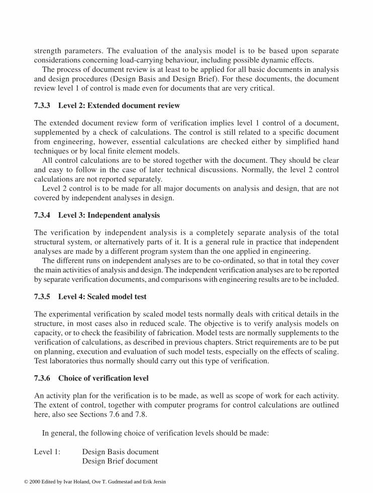
Verification of design 179
strength parameters. The evaluation of the analysis model is to be based upon separateconsiderations concerning load-carrying behaviour, including possible dynamic effects.
The process of document review is at least to be applied for all basic documents in analysisand design procedures (Design Basis and Design Brief). For these documents, the documentreview level 1 of control is made even for documents that are very critical.
7.3.3 Level 2: Extended document review
The extended document review form of verification implies level 1 control of a document,supplemented by a check of calculations. The control is still related to a specific documentfrom engineering, however, essential calculations are checked either by simplified handtechniques or by local finite element models.
All control calculations are to be stored together with the document. They should be clearand easy to follow in the case of later technical discussions. Normally, the level 2 controlcalculations are not reported separately.
Level 2 control is to be made for all major documents on analysis and design, that are notcovered by independent analyses in design.
7.3.4 Level 3: Independent analysis
The verification by independent analysis is a completely separate analysis of the totalstructural system, or alternatively parts of it. It is a general rule in practice that independentanalyses are made by a different program system than the one applied in engineering.
The different runs on independent analyses are to be co-ordinated, so that in total they coverthe main activities of analysis and design. The independent verification analyses are to be reportedby separate verification documents, and comparisons with engineering results are to be included.
7.3.5 Level 4: Scaled model test
The experimental verification by scaled model tests normally deals with critical details in thestructure, in most cases also in reduced scale. The objective is to verify analysis models oncapacity, or to check the feasibility of fabrication. Model tests are normally supplements to theverification of calculations, as described in previous chapters. Strict requirements are to be puton planning, execution and evaluation of such model tests, especially on the effects of scaling.Test laboratories thus normally should carry out this type of verification.
7.3.6 Choice of verification level
An activity plan for the verification is to be made, as well as scope of work for each activity.The extent of control, together with computer programs for control calculations are outlinedhere, also see Sections 7.6 and 7.8.
In general, the following choice of verification levels should be made:
Level 1: Design Basis documentDesign Brief document
© 2000 Edited by Ivar Holand, Ove T. Gudmestad and Erik Jersin

180 Verification of design
LoadsCriteria for capacity
Level 2: Secondary calculationsInternal verificationFinite element modelsLocal capacity controlsInterface analysis/capacity control
Level 3: Load modelsDesign wavesGlobal stress analysisLoad combinationCapacity control
Level 4: Global response (wind and waves)Capacity of vital detailsFabrication feasibility of details in full scale (reinforcement).
7.4 External verification
7.4.1 Alternatives in external verification
The present section deals with external (third party) verification of detail design, the objectivebeing to phase the verification work into the project organization. In addition, a set-up for third-party verification is outlined that enables engineering to profit from the verification work. Alternative 1: Operator controlled verificationFig. 7.2 illustrates the organization of the design project, including one box for engineering,one for operator and finally a separate box for third-party verification. The solid lines show theusual progression, in which all communication to third-party verification and back goes via theoperator. The system proposed also puts special requirements on the communication betweenoperator and engineering, as well as from operator to third party verification.
The above set-up for engineering control is based upon the system control by the operator,an activity that makes the need for a technical team by the operator. The third-party verificatortogether with the operator now comes out as one unit in discussion with engineering. Theoperator also sorts out the engineering activities for third-party verification, and decides theextent of verification. In practice, the verificator comes up with a budget for the work, which isthen the subject for discussions with the operator.
The lists of comments as well as the checklists from third-party verification are sent to theoperator for evaluation and possible completion. The final comments to engineering are madeby the operator. The operator also runs the subsequent technical discussions with engineering,as well as follow-up of non-conformances.
It emerges that the above organization of verification is both time consuming and expensive.
© 2000 Edited by Ivar Holand, Ove T. Gudmestad and Erik Jersin

Verification of design 181
The operator gets a key role in the clarification effort on comments from verification. Theheavy involvement of the operator in the technical discussions between engineering andverification also represents a large risk for time delays, and the gains from verification toengineering may disappear. Alternative 2: Direct communication between engineering and third party verificationAn alternative system for verification of engineering is illustrated in Fig. 7.3, involving directcommunication between engineering and verification. The formal responsibility is still by theoperator, as well as the task of discipline co-ordination. The main difference from the scheme inFig. 7.2 is that direct technical discussions now take place between engineering and verification.
7.4.2 Choice of alternative
The criteria for the selection of system for third-party verification are as follows:Criterion 1: Technical qualificationsThe sum of experience and theoretical basis by the operator and the third-party verificator foralternative 1, is to be compared to the qualifications by the verificator for alternative 2. Themain emphasis is laid upon key persons for the verification, their formal education as well asexperience from relevant projects.Criterion 2: Plan for third-party verificationA scope of work for verification is to be set out, including an activity plan and time schedulefor reporting back to engineering. In the selection of company for third-party verification, theabove activity description should be a major criterion.Criterion 3: CostBased on an estimate for man-hours a budget is to be made for the verification work. Theoperator may choose a split contract based on separate activities, or a type of frameworkagreement, with an upper limit on costs.
As seen from the above alternatives, the type and size of project are quite often decisive forthe choice of system for verification. In the case of operator supplement to third partyverification, the alternative in Fig. 7.3 should be chosen.
For both alternatives 1 and 2, the verificator is to report to the operator the work done. In thecase of alternative 2, lists of non-conformances are to be sent in parallel to engineering and tothe operator, and the operator may supplement this by comments.
7.5 Internal verification
The internal verification of results from engineering is to be included in the plan forverification, including personnel, level of control as well as technical subject for control.
© 2000 Edited by Ivar Holand, Ove T. Gudmestad and Erik Jersin
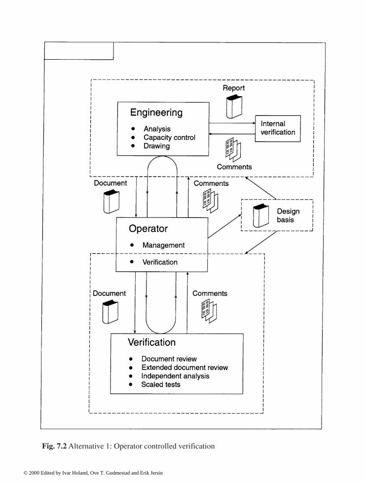
Fig. 7.2 Alternative 1: Operator controlled verification
© 2000 Edited by Ivar Holand, Ove T. Gudmestad and Erik Jersin

Fig. 7.3 Alternative 2: Direct communication between engineering and third partyverification
© 2000 Edited by Ivar Holand, Ove T. Gudmestad and Erik Jersin

184 Verification of design
Figs. 7.2 and 7.3 each shows a box for internal verification in engineering. The plan forverification should co-ordinate this activity with the overall set-up for the third-partyverification. The most common system is to have a separate group in engineering, thatfunctions like a group for third-party verification. All comments and the follow-up ofcomments from internal verification are then to be documented.
The alternative is that well-qualified personnel come into the engineering team with theirmajor effort on control. Communication to engineering is easier, and internal verification inengineering can now also become a daily support for the design work. It is, however, stillessential to keep the formal requirements intact, such as reporting of comments anddocumentation of the follow-up, even though the personnel doing the internal verification arein close contact with engineering.
Both the above alternatives involve the internal verification being an independent activityfrom engineering, so that the personnel for verification themselves do not have responsibilityfor design work.
7.6 Budgeting, reporting and follow-up of non-conformances
7.6.1 Budgeting
This section presents a system for the budgeting of the third-party verification activities. It alsodescribes forms of reporting by verification as well as follow-up of non-conformances.
Prior to the start of verification, a detailed plan is to be made, taking into account the controlactivities in verification as well as the treatment of non-conformances.
For the case of a split contract for third-party verification, or alternatively with a frameworkagreement, a budget for the verification work is to be made. The budget schemes contain thescope of work for each verification activity, together with planned man-hours and personnel.
A similar set-up should also be made for planning additional work during verification, eitheras an extension of existing activities, or by making a new scope of work.
Any exceedance of the budget has to be reported immediately and be subject to verification.Possible modifications of scope of work, so as to reduce the costs, need acceptance by the operator.
7.6.2 Reporting of non-conformances
The company responsible for verification is to produce a system for reporting on commentsand non-conformances, covering all four levels of verification. As far as possible, effort shouldbe made to keep the same form of reporting for level 1 and level 2 controls. The document onnon-conformances should have a standardized front page, see Fig. 7.4, together with a list forreporting and follow-up comments, Fig. 7.5.
The report on non-conformances is to be signed by the person with technical responsibilityfor the verification work. A checklist should follow each document from engineering, andproduce the major technical issues in the report. The engineer doing the verification work,should pay special attention to the checklist, and finally make their own evaluation of thecompletion of the different technical subjects.
© 2000 Edited by Ivar Holand, Ove T. Gudmestad and Erik Jersin

Verification of design 185
The comments from verification are to follow the document. In Fig. 7.5 the list fromverification contains the reference to engineering document, numbering of non-conformancesas well as a technical description of each comment, possibly also supplemented by sketches. Acolumn is also included for reporting on the follow-up, in which a signature confirms and datesthe verification of the corrective action, when agreement between engineering and verificationis obtained. Each list on non-conformances is to be checked and signed by the technicalsupervisor for verification.
Fig. 7.4 Front page on non-conformance report© 2000 Edited by Ivar Holand, Ove T. Gudmestad and Erik Jersin

186 Verification of design
Fig. 7.5 List of non-conformances
© 2000 Edited by Ivar Holand, Ove T. Gudmestad and Erik Jersin

Verification of design 187
7.7 Requirements concerning qualifications
7.7.1 Documentation of qualifications
Necessary qualifications are to be documented for the persons making the verification, in theform of formal education as well as relevant experience.
7.7.2 Requirements for technical leader for verification
A technical responsible person is to be identified by the third-party verificator. The primaryfunction of the technical leader is to evaluate all comments from verification to engineering,assuring that relevant comments are forwarded. A wide theoretical basis is necessary to coverglobal behavioural effects on the structure, as well as local problem areas. As a minimum, tenyears of experience in structural design should also be required in order to lead the verificationof larger projects.
The function of the technical leader is to evaluate the technical activities presented forverification and distribute these among the engineers for control. To follow up the controlwork, knowledge is also needed concerning special analyses on load effects, response analysisand design. The technical leader for verification is to check all comments that arise during thecontrol work and sort out the essential non-conformances that are to be forwarded. Thecomments also ought to be ranked with respect to critical aspects, making the discussion withengineering rational.
At certain milestones, the technical leader for verification is to report on the status ofprogress, highlighting on the critical items that are still not cleared from the list of non-conformances. Evaluations are then to be made whether the items still remaining require aredesign and thereby a stop in fabrication.
The technical leader represents the verification in all meetings with engineering and theoperator. Qualifications in technical presentations, also in foreign languages, are a requirementin larger projects.
7.7.3 Requirements for engineers
For the verification engineer in general, good basis within structural mechanics is necessary,including theory concerning load effects, stress analysis as well as capacity control. It isessential that tasks for the verification engineers are related to their qualifications. It is theresponsibility of the technical leader for verification to let the engineers have the relevantdocuments for control.
In the case of level 3 control by independent analysis, experience in the use of computerprograms is required. Further, structure behaviour knowledge is needed for making self controlof the level 3 analysis results, prior to reporting on possible non-conformances.
© 2000 Edited by Ivar Holand, Ove T. Gudmestad and Erik Jersin

188 Verification of design
7.8 Scope of verification activity
7.8.1 Planning of verification
The present section outlines the plans for some major activities within verification, theobjective being to come up with major issues in the verification of documents fromengineering. It is, however, to be emphasized that the activity schemes below do not representthe complete set of verification activities for a structure design project.
7.8.2 Verification of global analysis model
The control of the global model for stress analysis has its main objective to verify that the finiteelement mesh represents the load carrying behaviour of the structure. The verification is also toidentify areas where the model is not representative for the real structure behaviour and whereextra effort on design needs to be taken.
The control of the model follows the level 2 scheme of verification. The document on globalmodel by engineering is to have plots on section stress resultants and verification ought tocheck these with simplified techniques. Tests are to be made on the accuracy of the model inareas with high degrees of element distortions, ending up in a documentation of the feasibilityof the analysis model to handle certain complicated areas.
As a supplement to the document control of the global analysis model, an independentanalysis of stress results is to be performed by verification, applying an independent computerprogram. The modelling should include an evaluation of areas where separate analyses areneeded (D-regions).
The independent analysis model is related to the model from engineering, together withcomparisons on stresses for design. A separate document is made on the verification ofanalysis model.
7.8.3 Verification of design waves
The main objective of the present design wave verification is to assure that the waves fordesign calculations are representative for the load effects and the response characteristics ofthe structure.
The engineering evaluation of design waves is checked, involving the hydrodynamic model,unit amplitude waves, stochastic response analysis with extreme value estimates, as well aschoice of wave directions and range of wave periods.
For the hydrodynamic model, panel sizes are related to the shortest wave. The selection ofwave periods is related to the Design Basis document on environmental data, and the naturalperiods of the structure system.
The models for stress analysis are considered with major effort placed on element types thatare related to geometry, stiffness, mass and damping.
For the global rigid-body model on hydrodynamics, effort is to be placed on the control ofwave directions and periods. The wavelengths should also be related to the geometry of thestructure. Critical waves for essential load effects are sorted out by simplified frame models.
© 2000 Edited by Ivar Holand, Ove T. Gudmestad and Erik Jersin

Verification of design 189
For the stochastic analysis, the choice of wave input parameters is considered in parallelwith the Design Basis document and the NPD regulations (NPD, 1997). Extreme valueestimates from the stochastic analysis are compared with the hand-calculated responses, seeChapter 3. In general, the design wave period should be close to the predefined critical seastate peak period. Scaling of the amplitude of the design wave should also be given specialattention, The document control of verification, as described above, is a level 2 control withsimple supplementary calculations. Special attention is to be placed on the selection of designwaves, as these are fictive regular waves, representing the critical sea states for differentresponses in the structure.
7.8.4 Verification of loads in global model
The purpose of the present activity on load modelling verification is to check the application ofunit load cases, together with the scaling of responses into design combinations.
The basic load cases in the engineering analysis model are related to the different stages ofconstruction, installation and operation. Wave loading, together with current, wave drift andwind are checked against the Design Basis document, supplemented by estimates on forces.For the dynamic effects from waves, special care ought to be taken for the modelling of inertiaforces due to rigid-body motion of the structure.
Load effects from pretensioning are to be checked against the actual routing of cables.Evaluation is also to be made on possible modifications of the pretensioning system duringfabrication in heavily loaded areas to cover possible redesign.
The independent global model by verification also includes the load modelling referred toabove in Section 7.8.2.
7.8.5 Verification of design loads combinations
The activity on verification of design load combinations is essential in the way that it coversthe latest stage of calculations before fabrication drawings. Time co-ordination is important forthe present verification activity.
For different areas of the structure, design load combinations are taken out of the automaticprocess of capacity control. Plots of section forces are part of this information fromengineering. Then there are also stress resultants in the form of shell forces as well as globalstress resultants for columns and shafts. Often, verification is given direct access to theengineering files.
Based upon critical load combinations, estimates of stress resultants are made by simplifiedcalculations. The structure system depends on the stage of fabrication, installation or operation.
For cases where first order waves come into a design load combination, relevance to Section7.8.3 on design wave selection is appropriate. However, in combination with other load types,correlation between the different load effects is to be taken into account, and thus the criticalsingle wave does not necessarily come out as the worst wave for the combined load effect.
The selection of design waves is based upon scaling of regular wave responses to fit the
© 2000 Edited by Ivar Holand, Ove T. Gudmestad and Erik Jersin

190 Verification of design
extremes of a stochastic analysis. The process of design wave generation is made for a certainnumber of structure areas. The control of design waves from engineering should also include acheck of the correct design wave being applied for the structure part for which it is valid. Basedon the independent analysis control of stress resultants, a separate verification is made ofcapacity and reinforcement amounts.
References
Norwegian Petroleum Directorate (NPD), (1997) Acts, Regulations and Provisions for thePetroleum Activity. Norwegian Petroleum Directorate, Stavanger, Norway.
Statoil (1991) Structural Design for Offshore Installations, Specification for Design. N-SD-001, Statoil, Stavanger, Norway.
© 2000 Edited by Ivar Holand, Ove T. Gudmestad and Erik Jersin

Appendices
© 2000 Edited by Ivar Holand, Ove T. Gudmestad and Erik Jersin

Appendices 193
Appendix A Discipline Activity Model
Fixed platforms—Concrete substructures checklists
The objective of Appendix A is to present possible checklists for design of offshore concretesubstructures. Such checklists could be useful tools for the practical design to avoid importantsteps being missed out during the different stages of the design process.
The following key relates to checklists A1 through A5:
© 2000 Edited by Ivar Holand, Ove T. Gudmestad and Erik Jersin

194 Appendices
A1. Fixed platform—Concrete substructure design data checklist (3 pages)
5 Order of Magnitude
© 2000 Edited by Ivar Holand, Ove T. Gudmestad and Erik Jersin

Appendices 195
A1. Fixed platform—Concrete substructure design data checklist (3 pages)
© 2000 Edited by Ivar Holand, Ove T. Gudmestad and Erik Jersin

196 Appendices
A1. Fixed platform—Concrete substructure design data checklist (3 pages)
© 2000 Edited by Ivar Holand, Ove T. Gudmestad and Erik Jersin

Appendices 197
A2. Fixed platform—Concrete substructure activity checklist (2 pages)
© 2000 Edited by Ivar Holand, Ove T. Gudmestad and Erik Jersin
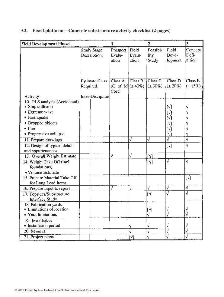
198 Appendices
A2. Fixed platform—Concrete substructure activity checklist (2 pages)
© 2000 Edited by Ivar Holand, Ove T. Gudmestad and Erik Jersin

Appendices 199
A3. Fixed platform—Concrete Substructure Design Tools Checklist (1 page)
© 2000 Edited by Ivar Holand, Ove T. Gudmestad and Erik Jersin

200 Appendices
A4. Fixed platform—Concrete Substructure Special Study Checklist (1 page)
© 2000 Edited by Ivar Holand, Ove T. Gudmestad and Erik Jersin

Appendices 201
A5. Fixed platform—Concrete Substructure Deliverables Checklist (1 page)
© 2000 Edited by Ivar Holand, Ove T. Gudmestad and Erik Jersin
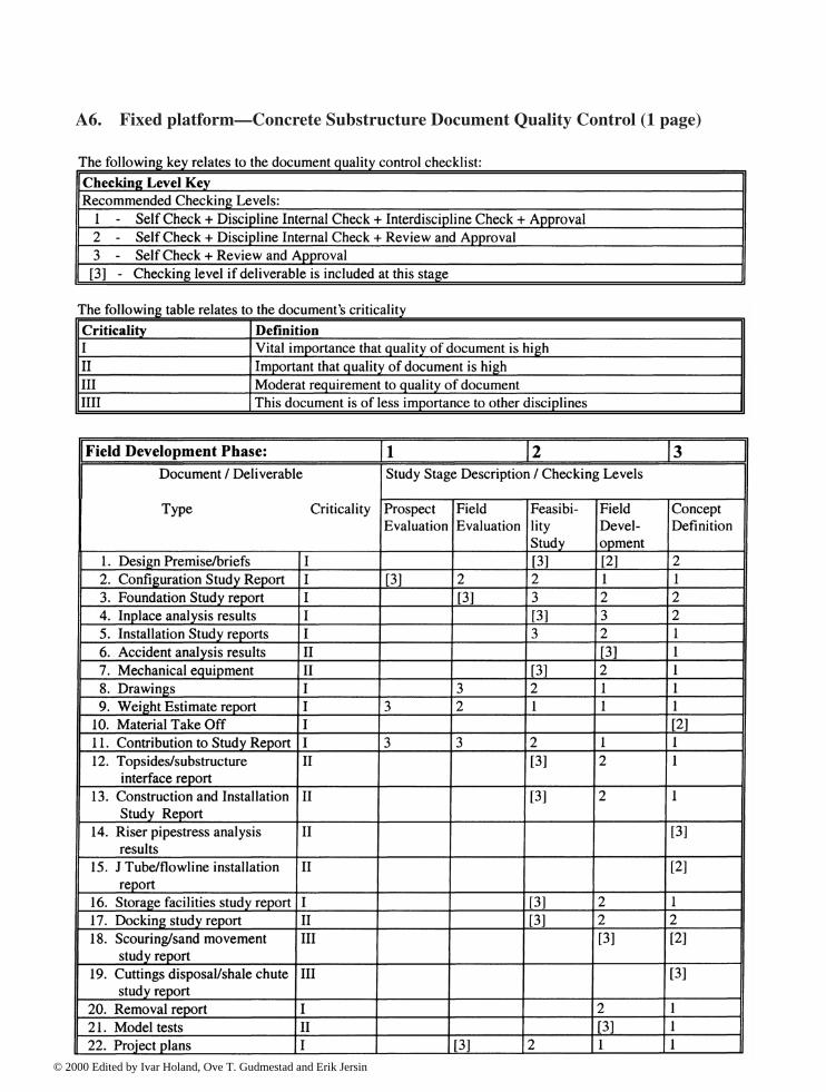
202 Appendices
A6. Fixed platform—Concrete Substructure Document Quality Control (1 page)
© 2000 Edited by Ivar Holand, Ove T. Gudmestad and Erik Jersin

Appendices 203
Appendix B Discipline Check (DC)
Definition: Discipline Check is a check to ensure that technical documents satisfyall internal and external requirements within one’s own discipline beforefurther distribution and use. A competent person, other than the one(s)that drew up the documents should carry out the check.
Purpose: To prevent defects and additional work in later phases due to thedocuments not being based on the correct assumptions or limitations, orthat they contain technical or formal defects or weaknesses.
Limitations: 1. Discipline Check does not guarantee that the interfaces to otherdisciplines are attended to. For this purpose, Inter Discipline Check(IDC) is used.
2. Discipline Check can be carried out by a person (or severalpersons) who has the same, or a higher level of competence thanthe person(s) who worked out the documents. DC adds safety incomparison to Self-Check, but does not in principle, due to theabove-mentioned reason, attend to other defects or weaknessesthan those that could have been discovered by a more detailedSelf Check.
Reference :Requirements * ISO 9001, item 4.1.2.2
* ISO 9001, item 4.4* ISO 9001, item 4.5.2* Norwegian Petroleum Directorate (NPD): Regulations for
structural design of loadbearing structures
Principles: 1. The individual Discipline Manager is responsible for carryingDC into effect within his own area of responsibility before thedocuments are distributed to others. If consultants are used therelevant Discipline Manager, if necessary supported by the QAdepartment, is also responsible for ensuring that DC has beencarried out at the consultant’s.
2. DC is carried out by checking that all internal and externalrequirements have been attended to, particularly the following:a) Accordance with the last, valid version of the Design Basis
(Design Baseline), which lays down the loads,environmental data and other functional requirements,conditions for use, geotechnical conditions, referencedocuments, etc. that will make up the basis for theengineering and design work.
b) Accordance with the last, valid version of the Design Brief,which describes how the engineering and design workshould be carried out (that is to say what important analyses,
© 2000 Edited by Ivar Holand, Ove T. Gudmestad and Erik Jersin
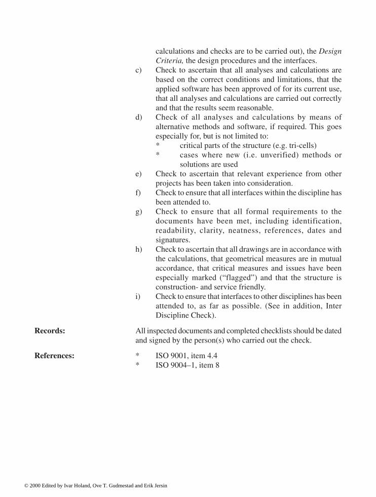
204 Appendices
calculations and checks are to be carried out), the DesignCriteria, the design procedures and the interfaces.
c) Check to ascertain that all analyses and calculations arebased on the correct conditions and limitations, that theapplied software has been approved of for its current use,that all analyses and calculations are carried out correctlyand that the results seem reasonable.
d) Check of all analyses and calculations by means ofalternative methods and software, if required. This goesespecially for, but is not limited to:* critical parts of the structure (e.g. tri-cells)* cases where new (i.e. unverified) methods or
solutions are usede) Check to ascertain that relevant experience from other
projects has been taken into consideration.f) Check to ensure that all interfaces within the discipline has
been attended to.g) Check to ensure that all formal requirements to the
documents have been met, including identification,readability, clarity, neatness, references, dates andsignatures.
h) Check to ascertain that all drawings are in accordance withthe calculations, that geometrical measures are in mutualaccordance, that critical measures and issues have beenespecially marked (“flagged”) and that the structure isconstruction- and service friendly.
i) Check to ensure that interfaces to other disciplines has beenattended to, as far as possible. (See in addition, InterDiscipline Check).
Records: All inspected documents and completed checklists should be datedand signed by the person(s) who carried out the check.
References: * ISO 9001, item 4.4* ISO 9004–1, item 8
© 2000 Edited by Ivar Holand, Ove T. Gudmestad and Erik Jersin
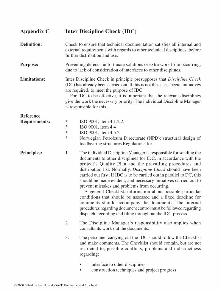
Appendices 205
Appendix C Inter Discipline Check (IDC)
Definition: Check to ensure that technical documentation satisfies all internal andexternal requirements with regards to other technical disciplines, beforefurther distribution and use.
Purpose: Preventing defects, unfortunate solutions or extra work from occurring,due to lack of consideration of interfaces to other disciplines.
Limitations: Inter Discipline Check in principle presupposes that Discipline Check(DC) has already been carried out. If this is not the case, special initiativesare required, to meet the purpose of IDC.
For IDC to be effective, it is important that the relevant disciplinesgive the work the necessary priority. The individual Discipline Manageris responsible for this.
ReferenceRequirements: * ISO 9001, item 4.1.2.2
* ISO 9001, item 4.4* ISO 9001, item 4.5.2* Norwegian Petroleum Directorate (NPD): structural design of
loadbearing structures Regulations for
Principles: 1. The individual Discipline Manager is responsible for sending thedocuments to other disciplines for IDC, in accordance with theproject’s Quality Plan and the prevailing procedures anddistribution list. Normally, Discipline Check should have beencarried out first. If IDC is to be carried out in parallel to DC, thisshould be made evident, and necessary initiatives carried out toprevent mistakes and problems from occurring.
A general Checklist, information about possible particularconditions that should be assessed and a fixed deadline forcomments should accompany the documents. The internalprocedures regarding document control must be followed regardingdispatch, recording and filing throughout the IDC-process.
2. The Discipline Manager’s responsibility also applies whenconsultants work out the documents.
3. The personnel carrying out the IDC should follow the Checklistand make comments. The Checklist should contain, but are notrestricted to, possible conflicts, problems and indistinctnessregarding:
• interface to other disciplines• construction techniques and project progress
© 2000 Edited by Ivar Holand, Ove T. Gudmestad and Erik Jersin
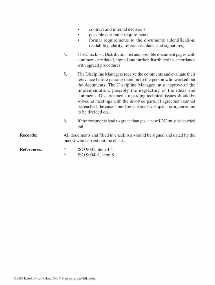
206 Appendices
• contract and internal decisions• possible particular requirements• formal requirements to the documents (identification,
readability, clarity, references, dates and signatures)
4. The Checklist, Distribution list and possible document pages withcomments are dated, signed and further distributed in accordancewith agreed procedures.
5. The Discipline Managers receive the comments and evaluate theirrelevance before passing them on to the person who worked outthe documents. The Discipline Manager must approve of theimplementation, possibly the neglecting of the ideas andcomments. Disagreements regarding technical issues should besolved at meetings with the involved parts. If agreement cannotbe reached, the case should be sent one level up in the organizationto be decided on.
6. If the comments lead to great changes, a new IDC must be carriedout.
Records: All documents and filled in checklists should be signed and dated by theone(s) who carried out the check.
References: * ISO 9001, item 4.4* ISO 9004–1, item 8
© 2000 Edited by Ivar Holand, Ove T. Gudmestad and Erik Jersin

Appendices 207
Appendix D Verification
Definitions: VerificationConfirmation by examination and provision of objective evidence thatspecified requirements have been fulfilled.[ISO 8402:1994]
Notes:1. In engineering, design and dimensioning, verification concerns
the process of examining the result of a given activity, to establishconformance with the stated requirements for that activity.Verification is thus a joint term for several elements of QualityAssurance which concern different types of internal and externalreviews, checks, inspections, tests, alternative calculations,surveillance’s and quality audits.
2. The term “verified” is used to designate the corresponding status.
Objective evidenceInformation, which can be proved to be true, based on facts obtained
through observation, measurement, test or other means.Independence
The verification is independent when personnel other than those whoare directly responsible for the work and the results that are to be verifiedcarry it out. Furthermore, the personnel should not report to the samemanager and they should be free from any pressure that may influenceon their judgement.Internal verification
Verification carried out by own employees.External Verification/Third Party’s Verification
Verification carried out by personnel employed by and reporting toanother organization/body.
Purpose: The purposes of all types of verification are the following:
1. Preventing defects and failures in the final product or service, aswell as preventing additional work and costs due tononconformities being discovered at a later point in time.
2. Providing evidence of, and thus greater confidence in, that therequirements have been met, and that the product will be well fitfor use.
Limitations: 1. The final proof of the product’s fitness for use can only be obtainedby real use. The applied technology and the verifying personnel’scompetence in each case limit the value of the verificationactivities.
© 2000 Edited by Ivar Holand, Ove T. Gudmestad and Erik Jersin
208 Appendices
2. The degree of independence is often of vital importance to theconfidence in the results of the verification. Internal verificationis necessary, but not always sufficient, for instance with respectto the authorities and one’s own management. Usually, the reasonbehind this is not suspecting occurrences of conscious actions oromissions, but rather the fact that the ability of someonediscovering defects in his/her own work is inferior to someone“from outside”. Besides, one cannot ignore the fact that the powerof judgement could be impaired due to stress, for instanceregarding time, money or the mere knowledge about potentialconsequences of discovering defects and nonconformities. Anexample of the latter would be if costly analyses or calculationshad to be redone if errors were discovered.
Example 1. The value of a simulation depends on how well the computerprogram has been tested (verified) for similar tasks previously, and thatthe operator handles the data and the program correctly and unaffectedby the desired result.
Example 2. A Design Review could be an efficient means of ensuringthat the previous experience and the total competence of the organizationare conveyed to the structure. However, a condition for this is that personswho have the adequate competence and experience carry out the review,and that sufficient time has been allocated for the purpose.
Example 3. When calculations which have been carried out by meansof Finite Element Analysis (FEA) are to be verified, a different methodshould be applied, or at least a different program. The reason behind thisis to avoid the same (systematic) mistakes from being repeated in theverification. In addition, it is presupposed that possible nonconformities,which have been discovered by the verification, will be subject to an in-depth analysis and assessment. If such nonconformity were explainedaway, for instance by claiming that a coarser model was used in theverification compared to in the original calculations, the verification wouldgive a false feeling of safety.
Referencerequirements: * ISO 9001, item 4.1.2.1
* ISO 9001, item 4.1.2.2* ISO 9001, item 4.4.7* ISO 9001, item 4.4.8* Norwegian Petroleum Directorate (NPD): Regulations for
structural design of loadbearing structures
Principles: 1. Both internal and external verification should in principle beindependent, that means carried out by personnel other than theperson(s) who is (are) directly responsible for the work that is tobe verified.
© 2000 Edited by Ivar Holand, Ove T. Gudmestad and Erik Jersin

Appendices 209
2. Regular verification should follow predetermined procedures.
3. Independent, external experts are often used in the verification ofhigh-technology activities or products. These experts should inprinciple be free to choose their own methods. Neither the projectteam nor others should direct the verification process in detail,for two reasons. First, because this often creates confusionregarding authority (who is responsible for what) and second,because it can reduce the confidence in the results of theverification. The verifying party in addition ought to have a majorimpact on which activities or results should be subject to (thirdparty) verification.
4. Verification during engineering, design and dimensioning can becarried out on four different levels (see Fig. 6.1):Level 1: Document ReviewLevel 2: Extended Document ReviewLevel 3: Independent CalculationsLevel 4: Scale Test(s).
Document Review involves a check to ascertain that all documents fromthe engineering and design phase (calculations, specifications, drawings,technical reports, etc.) are available, and impeccable, unambiguous andfit for use. The review could be carried out on all or some of the documents,depending on the criticality.
Document Review is not likely to reveal more basic defects, e.g. dueto the use of inferior methods.
Extended Document Review implies normal Document Reviewsupplied with checks of selected items. Those checks should bedocumented and filed together with the original document.
Independent Calculations should be carried out if the consequences ofpotential defects or nonconformities are major. The highest level of safety,and thus the greatest confidence, is achieved if a different method,computer program, computer, etc. is used. However, this is more timeconsuming. It is also required that methods, computer programs, etc.that are used during verification are themselves verified for the currentapplication. Simple analyses and manual calculations can in some casesbe an efficient, cheap and sufficient verification of the results.
Independent calculations should concentrate on the most critical partsof the structure.
Scale Test(s) imply that selected parts of the structure are built, usuallyon a smaller scale, and loaded or otherwise tested, under controlledconditions. The purpose could be to verify in practice that the structure isable to take the loads it has been dimensioned for, with the given marginsfor safety, and/or that it can be constructed and inspected with the
© 2000 Edited by Ivar Holand, Ove T. Gudmestad and Erik Jersin

210 Appendices
presupposed methods, tools, dimensions and materials. Due to practicaland economic reasons, such tests with large concrete structures usuallycannot be carried out on a full scale (1:1), When evaluating the results, itis of vital importance to take possible scale effects into consideration.
References: * ISO 9004–1, item 8.5* ISO 9001, item 4.4.7* ISO 9001, item 4.4.8
© 2000 Edited by Ivar Holand, Ove T. Gudmestad and Erik Jersin

Appendices 211
Appendix E Design Review (DR)
Definition: Documented, comprehensive and systematic examination of a design toevaluate its capability to fulfil the requirements for quality, identifyproblems, if any, and propose the development of solutions. [ISO8402:1994]
Purpose: Exploiting the total experience from previous projects to achieve anoptimal structure. It is, of course, particularly important to prevent seriousfaults, which can lead to structural breakdown.
Limitations: 1. Design Review is not alone sufficient to ensure a high qualitystructure.
2. The benefits of DR depends on the participants in the review,particularly their competence, experience from similar projectsand structures, creativity and ability to identify potential problems.
3. The Design Review is usually of advisory character. The effecttherefore also depends on the project leader having the will andability to take the advice into consideration.
Referencerequirements:
• NPD: Regulations for structural design of loadbearingstructures
• NPD: Regulations concerning the licensee’s internal controlin petroleum activities
• ISO 9001, item 4.4.6• NPD: Regulations concerning implementation and use of
risk analyses in petroleum activities
Principles: 1. Design Reviews can in principle be carried out in all phases duringengineering, design, dimensioning, construction and fabrication.The reviews should be included in the Project Plan or QualityPlan. Ad-hoc-like reviews should be arranged if considerablechanges in the functional specifications arise, or if needed due toparticular problems.
To characterise the individual reviews further, supplementarydesignations are often used, for instance:
• Preparatory Design Review• Following-up Design Review• Design Review of the Design Basis (Design Baseline)• Design Review of the Design Brief
© 2000 Edited by Ivar Holand, Ove T. Gudmestad and Erik Jersin

212 Appendices
• Design Review of the Design Criteria• Civil Design Review• Design Review of the Shaft Design• Design Review of tri-cell reinforcement, etc.• Mechanical Design Review• Engineering Readiness Review (often used before
permission to start the construction work is granted), etc.
2. The project leader, or the person he/she has authorised, isresponsible for preparing, summoning and leading the meetings,in co-operation with the QA department. The participants,sometimes called the Design Council, should be persons withrelevant competence regarding the themes that are to be dealtwith. Consultants, the authorities and/or contractors may beinvited, when appropriate. The necessary documents to bereviewed should always have been studied in advance.
3. Those themes which should be dealt with could include thestructure’s fitness for use, constructability, testability, strength,reliability, maintainability, safety, environmental considerations,life cycle costs, etc.
The result of DR could be:
• calling attention to nonconformities, weaknesses andpotential problems with the proposed solution, for instancein light of experience from other projects
• proposals for improvement• confirmation of favourable choices for solutions• agreement on the need for other reviews.
4. Minutes of the meetings should be drawn up. It is important togive the reasons for the advice and recommendations, as well. Ifthe project manager chooses not to follow the advice, the reasonfor this should also be recorded.
References:• ISO 9001, item 4.4.6• ISO 9004–1, item 8.4• ISO 9004–1, item 8.6• ISO 9004–1, item 8.7
© 2000 Edited by Ivar Holand, Ove T. Gudmestad and Erik Jersin

Appendices 213
Appendix F Hazard and Operability Analysis (HAZOP)
Definition: Formal, systematic and critical review of different parts of a system, designor structure in order to identify potential safety and operational problems.
Purpose: Identifying possible safety and/or operational problems that may ariseduring construction, operation and maintenance of a process plant or astructure. The analysis could be a complete risk analysis or a prestudy forlater, more detailed studies of certain critical parts of a plant or structure.
Limitations: 1. Any non-predicted hazard will not be part of the analysis.
2. The results depend on the competence of the analysis group.
3. HAZOP does not take human failures and common cause failuresinto account.
4. It is difficult to identify component failures and environmentaleffects as reasons for nonconformity.
Reference requirements:• NPD: Regulations for structural design of loadbearing structures• NPD: Regulations concerning the licensee’s internal control in
petroleum activities• NPD: Regulations concerning implementation and use of risk
analyses in the petroleum activities
Principles: HAZOP may be carried out as part of pre-engineering and/or detail design,as well as in connection with maintenance and/or modifications of thestructure, operation procedures, etc.
The analysis can be divided into 5 steps:1. Define the purpose of the study, the methodology and the time
schedule.
2. Select the members of the analysis group.
3. Prepare the analysis work.
4. Carry out the analysis.
5. Record the results.
The analysis group should be made up of persons with differentbackgrounds, who have special competence within their own field. Thegroup usually consists of a leader, a secretary plus 4–6 additional persons,depending on the size and the complexity of the object of the analysis. Ifthere is a need for it, other persons can be brought in. The work is mainly
© 2000 Edited by Ivar Holand, Ove T. Gudmestad and Erik Jersin

214 Appendices
carried out in a series of brainstorming meetings, conducted by the leader.The process demands much from the leader of the working group; he orshe ought to have previous experience with HAZOP.
The analysis is normally done on the basis of drawings, constructionprocedures, etc.
The analysis work starts by clarifying the purpose and the normalcondition of the elements that are to be evaluated. The work is directedby the HAZOP-leader by means of a series of guiding words andchecklists. Examples of guiding words are “none”, “bigger than”, “smallerthan”, etc. Every guiding word is used on different structure elements atthe specific items that are to be examined. By means of these guidingwords, possible nonconformances from the normal condition in everystructural element are identified, as well as the reason(s) behindnonconformity and the consequences. The analysis should be carried outfor different conditions.
The results should be verifiable and recorded by means of a HAZOPReport Form. The form should as a minimum contain a column for guidingwords, nonconformances, causes, consequences, recommenda tions andcomments. The latter could, for example, be questions for the projectmanager, recommendations regarding changes in design or commentsabout particular risks that ought to be dealt with in special procedures.
References: * NS 5814:1991 Requirements to risk analyses* Rausand, Marvin, 1991: Risikoanalyse—Veiledning til NS 5814,
Tapir, Trondheim. (This is a guide to the Norwegian Standard NS5814.)
© 2000 Edited by Ivar Holand, Ove T. Gudmestad and Erik Jersin
Appendices 215
Appendix G Worst-Case Analysis
Definition: Systematic analysis and assessment of the consequences of the worstpossible input data, occurrences and combinations of occurrences forpeople, the environment and assets.
Purposes: 1. To verify that safety and other important functions are maintainedunder abnormal loads, foreseeable abuse and abnormal humanstress.
2. To ensure that possible decisions on not dimensioning for suchextreme conditions are made on the right (i.e. a high enough)level in the organization.
Limitations: In worst-case analyses, only those occurrences and combinations ofoccurrences which have been identified beforehand, and assessed to beof current interest to such analyses, are dealt with.
Referencerequirements: * NPD: Regulations for structural design of loadbearing structures
Principles: 1. Worst-case analyses should be carried out for critical designparameters to obtain a general view of the consequences forpersonnel, the environment and material values due to extremestresses that may occur in connection with testing, operation andmaintenance. The environment may cause such extreme stresses,by single occurrences or by combinations of occurrences. Theassessment may start out with the normal condition of theinstallation. Alternatively, potential nonconformity’s can form thestarting point. For example, the normal condition would be thatall reinforcement has been installed as planned, while a potentialnonconformity might be that 5% of the reinforcement is lackingor seriously corroded in critical sections of the structure.
2. In order for worst-case analyses to be carried out, there ought tobe a certain probability for the occurrence(s) to happen. Theidentification of those occurrences and conditions should be basedon a systematic review of the installation.
3. The worst possible occurrences might be analysed one by one, oras a combination of occurrences. Such combinations should bepossible, although not very likely to happen at the same time.The analysis of combinations could be by means of a systematicreview of different scenarios, e.g. in the form of a matrix.
4. Worst-case analyses do not use a particular technique or method;it is rather a philosophy for finding out how robust the installation
© 2000 Edited by Ivar Holand, Ove T. Gudmestad and Erik Jersin

216 Appendices
is under the influence of extreme conditions and stresses. Theprinciple can be used both in risk analyses and also for instancein stress calculations and dimensioning.
5. The analyses should be documented in a verifiable manner. Inaddition the basis for the choice of the analysed occurrences shouldbe recorded.
6. The results could for example be expressed like this: “The structureis robust against the influence”, “Risk reducing action ought tobe carried out” or “The probability of the occurrences happeningis too small—no action is required”.
7. The result of the analysis should form a basis for decisions.
Examples: a) Calculation of the structure’s ability to withstand the 10.000-yearwave.
b) Calculation of the structure’s stability during an earthquakecombined with a hurricane and insufficient maintenance.
c) Assessment of the consequences if all uncertainties in thedimensioning would be pulling in the same, unfortunate directionand at the same time 5% of the reinforcement would be lackingor seriously corroded in critical sections.
d) Assessment of the consequences, if one of the structural elementsshould be torn off (as in the “Alexander L. Kielland”6 case).
6 “Alexander L.Kielland” was a semi-submersible flotel which capsized in the Northern Sea on March 27, 1980. The direct/immediate causeof the loss was that one of the 5 platform legs was torn off, due to extremely heavy weather conditions.
© 2000 Edited by Ivar Holand, Ove T. Gudmestad and Erik Jersin

Appendices 217
Appendix H Quality Audit/Quality System Audit
Definitions: Quality AuditSystematic and independent examination to determine whether quality
activities and related results comply with planned arrangements andwhether these arrangements are implemented effectively and are suitableto achieve objectives. [ISO 8402:1994]Audit Program
General view of the planned audits for a particular period of time.Audit Plan
Detailed plan for the carrying out of a particular audit.Observation
A statement of fact made during an audit and substantiated by objectiveevidence. [ISO 10011–1:1992]Objective Evidence
Qualitative or quantitative information, records or statements of factspertaining to the quality of an item or service or to the existence andimplementation of a quality system element, which is based onobservation, measurement or test and which can be verified. [ISO 10011–1:1992], see also Appendix 3 Verification.Nonconformity
Non-fulfilment of specified requirements. [ISO 8402:1994]Recommendation
The audit team’s proposal for improvement of the auditee’s systems.
Purposes: Quality System Audit is carried out with one or more of the followingintentions in mind:a) Ascertain whether the elements in the Quality System comply
with the requirements of the company and the authorities, as abasis for pre-qualification of a supplier or contractor or as a partof the follow-up of a contract.
b) Assess how effective the Quality System is implemented when itcomes to meeting the goals for quality.
c) Give the auditee an opportunity to improve the Quality System.
Limitations: 1. Quality Audits can and should contribute to a safe and efficientproject execution, but it can never guarantee that nonconformitywill not occur or that it is detected in time. The situation could becompared to the car-driving test (as basis for issuing a drivinglicence); the test is a means of ensuring safe driving, but it cannotguarantee that the driver will never cause accidents.
2. The audit will in practice be based on spot tests, which, of course,affects the reliability.
© 2000 Edited by Ivar Holand, Ove T. Gudmestad and Erik Jersin

218 Appendices
3. The effectiveness of the audit depends on the competence of theauditor(s) and the auditee’s will and power to participate andcooperate, both during the audit and with regard to implementingcorrective actions.
Reference requirements:• NPD: Regulations for structural design of loadbearing
structures• NPD: Regulations concerning the licensee’s internal control
in petroleum activities• ISO 9001, item 4.17
Principles: 1. Regular quality audits are done in accordance with a drawn upaudit program. Audits could also be caused by significant changesin the quality system or the quality of delivered products orservices, or in order to follow up Corrective Action Requests(CAR). When selecting the areas to be audited, emphasis shouldbe put on how critical the activity is when it comes to the safetyand fitness for use of the product or service and the vulnerabilityregarding nonconformities.
2. The Quality Audit typically applies to, but is not limited to, thequality system or elements thereof and to processes, productsand services. Such audits may be called, respectively:* Quality System Audit* Process Quality Audit* Product Quality Audit* Service Quality Audit, etc.
Quality System Audit is the one most frequently used. The basicprinciples are, however, the same for all of them. Quality Auditcan also be termed according to when in the engineering anddesign or construction process it is carried out, e.g. in connectionwith pre-qualifying of supplier, or before commissioning. (Thelatter is often called Implementation Quality Audit or sometimesImplementation Review.)
3. Audits should be carried out in accordance with ISO 10011–1, –2 and –3; Guidelines for auditing quality systems. The standardsgive guidelines for the following conditions:a) The responsibilities and tasks of the audit team and audit
leader.b) The qualification requirements to the auditors and the audit
leader.c) Planning, preparation, carrying out and reporting the audit.d) Follow-up of Corrective Action Requests.
© 2000 Edited by Ivar Holand, Ove T. Gudmestad and Erik Jersin

Appendices 219
Records: The Quality Audit should be reported and recorded in accordance withthe guidelines in ISO 10011–1. The audit is not “closed” until it is verifiedand duly signed to show that all the Corrective Action Requests havebeen properly dealt with.
References: * ISO 9004–1, item 5.4* ISO 10011–1, –2, –3 Guidelines for auditing quality systems;
Part 1: AuditingPart 2: Qualification criteria for quality system auditorsPart 3: Management of audit programmes
© 2000 Edited by Ivar Holand, Ove T. Gudmestad and Erik Jersin