design of outfall and culvert details · normal calculation method and the backwater calculation...
TRANSCRIPT

Design of Outfall and Culvert Details
DN-DNG-03071 March 2015
Design Standards DN
TRANSPORT INFRASTRUCTURE IRELAND (TII) PUBLICATIONS
About TII Transport Infrastructure Ireland (TII) is responsible for managing and improving the country’s national road and light rail networks. About TII Publications TII maintains an online suite of technical publications, which is managed through the TII Publications website. The contents of TII Publications is clearly split into ‘Standards’ and ‘Technical’ documentation. All documentation for implementation on TII schemes is collectively referred to as TII Publications (Standards), and all other documentation within the system is collectively referred to as TII Publications (Technical). This system replaces the NRA Design Manual for Roads and Bridges (NRA DMRB) and the NRA Manual of Contract Documents for Road Works (NRA MCDRW). Document Attributes Each document within TII Publications has a range of attributes associated with it, which allows for efficient access and retrieval of the document from the website. These attributes are also contained on the inside cover of each current document, for reference. For migration of documents from the NRA and RPA to the new system, each current document was assigned with new outer front and rear covers. Apart from the covers, and inside cover pages, the documents contain the same information as previously within the NRA or RPA systems, including historical references such as those contained within NRA DMRB and NRA MCDRW. Document Attributes
TII Publication Title Design of Outfall and Culvert Details TII Publication Number
DN-DNG-03071
Activity Design (DN) Document Set Standards
Stream Drainage (DNG) Publication Date March 2015
Document Number
03071 Historical Reference
NRA HD 107
NRA DMRB and MCDRW References For all documents that existed within the NRA DMRB or the NRA MCDRW prior to the launch of TII Publications, the NRA document reference used previously is listed above under ‘historical reference’. The TII Publication Number also shown above now supersedes this historical reference. All historical references within this document are deemed to be replaced by the TII Publication Number. For the equivalent TII Publication Number for all other historical references contained within this document, please refer to the TII Publications website.

Design of Outfall and Culvert Details
Volume 4 Section 2 Part 4
NRA HD 107/15
March 2015
St. Martin’s House, Waterloo Road, Dublin 4 Tel: +353 1 660 2511 Fax +353 1 668 0009 Email: [email protected] Web: www.nra.ie

Summary:
This Standard gives guidance on detailing of outfall structures to road drainage systems and design of culverts including scour but excluding hydraulic design.
Published by National Roads Authority, Dublin 2015
NRA DESIGN MANUAL FOR ROADS AND BRIDGES
March 2015 i
VOLUME 4 GEOTECHNICS AND DRAINAGE
SECTION 2 DRAINAGE
PART 4
NRA HD 107/15
DESIGN OF OUTFALL AND CULVERT DETAILS
Contents
Chapter
1. Introduction
2. Road Drainage Outfalls
3. Outfall Details
4. Culverts: Introduction
5. Culverts: Location and Layout
6. Culverts: Flood Estimation
7. Culverts: Scour Issues
8. Culverts: Screen Details
9. Culverts: Environmental Aspects
10. Culverts: Maintenance Issues
11. References
12. Enquiries
APPENDIX A: Construction Details
APPENDIX B: Culvert Alignment Options

National Roads Authority Volume 4 Section 2 Design Manual for Roads and Bridges Part 4 NRA HD 107/15
March 2015 2
1. INTRODUCTION General
1.1 This Standard gives guidance on detailing of outfall structures from road drainage systems and design of culverts including scour but excluding hydraulic design. Advice on the hydraulic design of culverts is given in CIRIA 689 Culvert Design and Operation Guide. The guidance given in this Standard relates to adapting the guidance, given in the CIRIA document, specifically for road applications.
1.2 This Standard contains guidance on the construction of outfalls from road drainage systems to, principally, natural channels, watercourses, or purpose-made drainage channels. In Ireland, consent is required from the Office of Public Works (OPW), under the Arterial Drainage Acts, 1945 and 1995, for the creation and modification of watercourses, embankments, weirs and bridges. These requirements shall apply to all pre-defined watercourses that fall under the remit of the OPW and take priority over guidance provided in this Standard. Earthworks drainage designed to intercept and convey overland flow approaching National Road projects and perimeter field ditches are understood not to be covered under the scope of OPW requirements and the designer should follow the guidance in this Standard and NRA HD 106 Drainage of Runoff from Natural Catchments for these elements.
1.3 In assessing the hydraulic design reference should be made to CIRIA 689, except for flood estimation purposes where primary reference should be made to the OPW flood risk management requirements (www.opw.ie/en/floodriskmanagement/) and secondary reference to NRA HD 106.
1.4 In addition to the advice contained herein, the design of flood alleviation culverts where a road is constructed across a floodplain, primary reference should be made to the OPW flood risk management requirements (www.opw.ie/en/floodriskmanagement/) and secondary reference to NRA HD 45 Road Drainage and the Water Environment.
1.5 The 2015 revision of the NRA’s drainage standards was precipitated by post-doctoral research carried out under the NRA’s Research Fellowship Programme and mentored by the NRA’s Environment Unit. This research looked at the impacts of national road drainage systems on both surface and ground water. The research concluded that the NRA’s drainage standards needed to be expanded to promote the use of sustainable drainage systems and to maximise environmental benefits. A report entitled Drainage Design for National Road Schemes – Sustainable Drainage Options (NRA, 2014) documents this research and provides useful background reading to the NRA’s drainage standards. This document is available at: nrastandards.nra.ie/latest/other-nra-documents.
Scope
1.6 The principles outlined in this Standard apply to all National Roads projects.
Implementation
1.7 This Standard shall be used forthwith for all schemes for the construction and/or improvements of National Roads projects. It shall be applied to the design of schemes already being prepared unless, in the opinion of the National Roads Authority, application would result in significant additional expense or delay progress. In such cases, Design Organisations shall confirm the application of this Standard to particular schemes with the National Roads Authority.

National Roads Authority Volume 4 Section 2 Design Manual for Roads and Bridges Part 4 NRA HD 107/15
March 2015 3
2. ROAD DRAINAGE OUTFALLS General
2.1 The term outfall is applied to the point where the road drainage system discharges into a different type of drainage system: this maybe natural channels, watercourses, or purpose-made drainage channels. For the purposes of this Standard, outfalls are to either ditches or receiving watercourses.
2.2 Where the outfall is to a watercourse, the arrangement detail should be determined in consultation with the relevant authorities (e.g. local authorities, Environmental Protection Agency (EPA), Inland Fisheries Ireland (IFI), National Parks & Wildlife Service (NPWS)). Flood data provided by the OPW (www.floodmaps.ie) should also be consulted.
Outfall to ditch
2.3 The ditch may drain the carriageway, verge and the adjacent unpaved area. However, water from the road drainage system is likely to discharge to the ditch long before that from the adjacent land, the time of concentration being a matter of minutes for the road drainage system and hours for the adjacent unpaved areas.
2.4 Outfalls to ditches and watercourses will generally be either from individual pipes or the outlet from an upstream system. Individual pipe outlets can be formed from rendered concrete blockwork, cast in-situ reinforced concrete, pre-cast concrete units, or other suitable proprietary products. Refer to Series 500 of the NRA Road Construction Details (NRA RCD) for headwall details.
2.5 The components of the outfall structures are described in greater detail in Chapter 3.
Outfall to watercourse
2.6 It is important to determine the top water levels of the receiving watercourse both in dry and wet weather conditions. The road pavement is much more responsive to rainfall run-off than the surrounding natural catchment so, generally, the peak discharge from the outfall pipe occurs before that in the watercourse. It may therefore be necessary to protect the bed and banks from scour (see Chapter 3).
2.7 It is also possible that during periods of prolonged heavy rainfall the flow in the receiving watercourse may rise above the invert level of the outfall pipe. The design of the road drainage system shall be assessed to investigate the effects of a drowned outfall. NRA HD 33 Drainage Systems for National Roads outlines further outfall requirements with respect to watercourse top water levels.
2.8 If recent flooding has been experienced, then data relating flow depth in the channel to flow rate may be available from the local authority, EPA or OPW. The designer should be aware of the accuracy of such information and also the difference between the calculated design flow and the flow depth obtained from the recorded data.
2.9 The water surface profile can be calculated for the backwater length formula
Lbw = 0.7D/s
where D is the bank full depth and s is the slope of the water surface (or bed surface where that of the water is unavailable). The designer should refer to the CIRIA 689 for the worked example on the normal calculation method and the backwater calculation method.

National Roads Authority Volume 4 Section 2 Design Manual for Roads and Bridges Part 4 NRA HD 107/15
March 2015 4
2.10 Typical Manning’s n values for channel roughness are tabulated in Table 2.1. This table is more comprehensive than information contained in the CIRIA 689 and it is recommended that designers use Table 2.1 values in their calculations.
Table 2.1: Typical values for Manning’s “n”
Natural Stream
Lowland Streams
Min Normal Max
1. Clean, straight, full stage, no rifts or pools 0.025 0.030 0.033
2. As above with more stones and weeds 0.030 0.035 0.40
3. Clean, winding, some pools and shoals 0.033 0.040 0.045
4. As above with some weeds and stones 0.035 0.045 0.050
5. As above, lower stages, more ineffective slopes & sections 0.040 0.048 0.055
6. As 4 above with more stones 0.045 0.050 0.060
7. Sluggish reaches, weedy, deep pools 0.050 0.070 0.080
8. Very weedy reaches, deep pools & heavy timber stand 0.075 0.100 0.150
Mountain Streams
1. Bottom: gravels, cobbles, and few boulders 0.030 0.040 0.050
2. Bottom: cobbles with large boulders 0.040 0.050 0.070
Excavated Channel
1. Gravel, straight uniform, clean 0.022 0.030 0.033
2. Straight, uniform, short grass and weeds 0.022 0.027 0.033
3. Winding and sluggish, grass some weeds 0.025 0.030 0.033
4. Winding, sluggish, dense weeds or plants in deep channels 0.030 0.035 0.040
5. Winding, sluggish, earth bottom, rubble sides 0.028 0.030 0.035
6. Winding, sluggish, stony bottom, weedy banks 0.025 0.035 0.040
7. Winding, sluggish, cobble bottom, clean sides 0.030 0.040 0.050
8. Dredged light brush on banks 0.035 0.050 0.060
9. Rock smooth and uniform 0.025 0.035 0.040
10. Rock jagged and irregular 0.035 0.040 0.050
Unmaintained excavated channel, weeds/brush uncut
1. Dense weeds, high as flow depth 0.050 0.080 0.120
2. Clean bottom, brush on both sides 0.040 0.050 0.080
3. As 2, highest stages of flow 0.045 0.070 0.110
4. Dense brush, high stage 0.080 0.100 0.140
2.11 Ordnance Survey maps may be used to determine initial watercourse or ditch channel gradients for preliminary design calculations, however accurate cross-sectional dimensions will be necessary for more detailed designs.
Outfall Design
2.12 Determine or estimate the top water level in the receiving watercourse or ditch channel for the corresponding design storm applicable to the road drainage system design (NRA HD 33). The invert level of the outfall pipe should be at or above this level.
2.13 The top water level of the receiving watercourse or ditch should then be assessed for more intense storms up to a 1 in 100 year storm event to determine the extent of any adverse impacts compared with the existing scenario.

National Roads Authority Volume 4 Section 2 Design Manual for Roads and Bridges Part 4 NRA HD 107/15
March 2015 5
2.14 Should the outfall pipe be partially submerged under the above conditions, then the designer should consider increasing the diameter of the upstream pipeline. This will enable a greater volume of flow to pass through the pipeline, however, the designer should assess the part-full flow characteristics of the partially submerged pipes using appropriate hydraulic modelling software.
National Roads Authority Volume 4 Section 2 Design Manual for Roads and Bridges Part 4 NRA HD 107/15
March 2015 6
3. OUTFALL DETAILS General
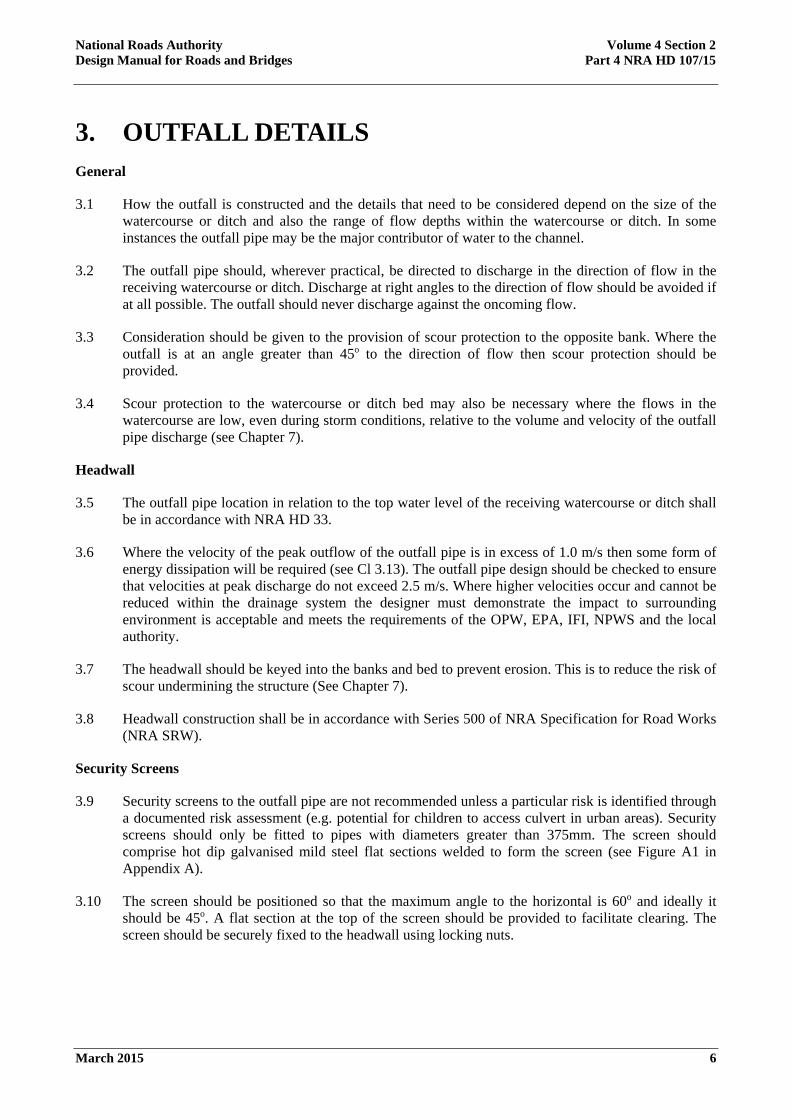
3.1 How the outfall is constructed and the details that need to be considered depend on the size of the watercourse or ditch and also the range of flow depths within the watercourse or ditch. In some instances the outfall pipe may be the major contributor of water to the channel.
3.2 The outfall pipe should, wherever practical, be directed to discharge in the direction of flow in the receiving watercourse or ditch. Discharge at right angles to the direction of flow should be avoided if at all possible. The outfall should never discharge against the oncoming flow.
3.3 Consideration should be given to the provision of scour protection to the opposite bank. Where the outfall is at an angle greater than 45o to the direction of flow then scour protection should be provided.
3.4 Scour protection to the watercourse or ditch bed may also be necessary where the flows in the watercourse are low, even during storm conditions, relative to the volume and velocity of the outfall pipe discharge (see Chapter 7).
Headwall
3.5 The outfall pipe location in relation to the top water level of the receiving watercourse or ditch shall be in accordance with NRA HD 33.
3.6 Where the velocity of the peak outflow of the outfall pipe is in excess of 1.0 m/s then some form of energy dissipation will be required (see Cl 3.13). The outfall pipe design should be checked to ensure that velocities at peak discharge do not exceed 2.5 m/s. Where higher velocities occur and cannot be reduced within the drainage system the designer must demonstrate the impact to surrounding environment is acceptable and meets the requirements of the OPW, EPA, IFI, NPWS and the local authority.
3.7 The headwall should be keyed into the banks and bed to prevent erosion. This is to reduce the risk of scour undermining the structure (See Chapter 7).
3.8 Headwall construction shall be in accordance with Series 500 of NRA Specification for Road Works (NRA SRW).
Security Screens
3.9 Security screens to the outfall pipe are not recommended unless a particular risk is identified through a documented risk assessment (e.g. potential for children to access culvert in urban areas). Security screens should only be fitted to pipes with diameters greater than 375mm. The screen should comprise hot dip galvanised mild steel flat sections welded to form the screen (see Figure A1 in Appendix A).
3.10 The screen should be positioned so that the maximum angle to the horizontal is 60o and ideally it should be 45o. A flat section at the top of the screen should be provided to facilitate clearing. The screen should be securely fixed to the headwall using locking nuts.

National Roads Authority Volume 4 Section 2 Design Manual for Roads and Bridges Part 4 NRA HD 107/15
March 2015 7
Flap Valves
3.11 Flap valves prevent the back flow of water from the receiving watercourse or ditch into the road drainage systems. Their presence may cause a significant head loss to the discharge flows and hence reduce the capacity of the latter sections of the system. An allowance should be made during the hydraulic design. Where any pipeline is at risk of being submerged by the flows in the watercourse or ditch or where the drainage system discharges to a tidal reach, then a flap valve may be installed. The designer should assess the possible adverse effects that may arise due to the use of a flap valve.
3.12 Where the outfall may be accessible to members of the public, coplastics (composite plastic) valves rather than cast or ductile iron may be less susceptible to vandalism.
Energy Dissipation
3.13 The velocity of the flow within the outfall pipe may be sufficient to cause erosion of the bed and bank of the receiving watercourse or ditch. This is more likely to occur where the gradient of the outfall pipe is steep and/or where the peak volume of the flow within the outfall pipe is similar or greater than that of the receiving watercourse or ditch. Note that the peak rate of discharge from the outfall pipe will usually occur many hours before the peak flow rate of the watercourse or ditch.
3.14 Where the peak discharge velocity of the outfall pipe is in excess of 1.0 m/s, some form of energy dissipation will be required.
3.15 The principle types are:
a) Stilling basin: this is the preferred option from a maintenance aspect although this requires a longer structure and hence may be precluded due to land take considerations. Consultation with IFI, OPW, NPWS, EPA and the local authority should be carried out, as required.
b) Concrete revetment: this consists of concrete blocks or teeth cast on to the apron to interrupt the flow and hence dissipate energy. There is a maintenance issue in that the blocks will trap debris, especially from the watercourse. Concrete blocks within fish bearing watercourses can lead to abrasion of fish and natural rounded stones are more suitable. Consultation with IFI, OPW, NPWS, EPA and the local authority should be carried out as required.
c) Rock Amour: this consists of a layer of material used to armour the watercourse or ditch banks. It is made from graded, preferably angular stone and regular in shape. Consultation with IFI, OPW, NPWS, EPA and the local authority should be carried out as required.
3.16 It is often appropriate to reinforce the watercourse bank opposite the point of discharge in order to reduce the risk of erosion. Rock armour using natural stone is the preferred option rather than concrete revetment, a wall or stone gabions.

National Roads Authority Volume 4 Section 2 Design Manual for Roads and Bridges Part 4 NRA HD 107/15
March 2015 8
4. CULVERTS: INTRODUCTION General
4.1 The following features are considered good practice:
Hydraulic Performance
a) Adequate size to ensure that design flows are accommodated without surcharge and that debris can pass through the culvert
b) No changes of direction within the culvert or steps in the invert
c) Streamline both the inlet and outlet
d) Constant gradient through the culvert, maintaining the gradient of the watercourse or ditch
e) Self-cleansing, to ensure that no silt is deposited
f) Free from internal fittings that may snag debris
Environmental
g) Accommodates wildlife and fish migration with regard to velocity and flow characteristics
h) Is aesthetically complementary to the adjacent surroundings
Safety Requirements
i) Constructed to be traversed safely when within the clear zone
j) Presents no safety hazard to maintenance workers or the public
k) Access incorporates features such as hand rails and steps where appropriate
l) Where practical access does not cross third party land
m) Screens are omitted or designed to be cleared without entering the watercourse or ditch
Budgetary
n) Lowest whole-life costs
4.2 Culverts for conveying a watercourse from one side of the carriageway to the other have greater design requirements than those forming part of the road drainage system. Most of the foregoing conditions are also applicable to ditches or earthworks drainage culverts, however due to the fluctuating nature of flows, deposition of silt is inevitable. The diameters of this type of culvert tend to be small and hence access for maintenance should be incorporated into the design (see Chapter 10).
4.3 Watercourse culverts are subject to regulation under Section 50 of the Arterial Drainage Act, 1945, as amended and compliance is managed by the OPW. Requirements for watercourse culverts are stipulated by the OPW (www.opw.ie/en/floodriskmanagement/) and shall take precedence to requirements outlined in this standard. Generally ditches and earthworks drainage culverts are outside the scope of these requirements and are only subject to the requirements of this standard and NRA HD 106.
National Roads Authority Volume 4 Section 2 Design Manual for Roads and Bridges Part 4 NRA HD 107/15
March 2015 9
Culvert Shape
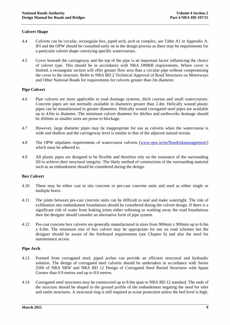
4.4 Culverts can be circular, rectangular box, piped arch, arch or complex, see Table A1 in Appendix A. IFI and the OPW should be consulted early on in the design process as there may be requirements for a particular culvert shape conveying specific watercourses.
4.5 Cover beneath the carriageway and the top of the pipe is an important factor influencing the choice of culvert type. This should be in accordance with NRA DMRB requirements. Where cover is limited, a rectangular section will offer greater flow area than a circular pipe without compromising the cover to the structure. Refer to NRA BD 2 Technical Approval of Road Structures on Motorways and Other National Roads for requirements for culverts greater than 2m diameter.
Pipe Culvert
4.6 Pipe culverts are more applicable to road drainage systems, ditch courses and small watercourses. Concrete pipes are not normally available in diameters greater than 2.4m. Helically wound plastic pipes can be manufactured to greater diameters. Helically wound corrugated steel pipes are available up to 4.0m in diameter. The minimum culvert diameter for ditches and earthworks drainage should be 450mm as smaller sizes are prone to blockage.
4.7 However, large diameter pipes may be inappropriate for use as culverts when the watercourse is wide and shallow and the carriageway level is similar to that of the adjacent natural terrain.
4.8 The OPW stipulates requirements of watercourse culverts (www.opw.ie/en/floodriskmanagement/) which must be adhered to.
4.9 All plastic pipes are designed to be flexible and therefore rely on the resistance of the surrounding fill to achieve their structural integrity. The likely method of construction of the surrounding material such as an embankment should be considered during the design.
Box Culvert
4.10 These may be either cast in situ concrete or pre-cast concrete units and used as either single or multiple bores.
4.11 The joints between pre-cast concrete units can be difficult to seal and make watertight. The risk of exfiltration into embankment foundations should be considered during the culvert design. If there is a significant risk of water from leaking joints either softening or washing away the road foundations then the designer should consider an alternative form of pipe system.
4.12 Pre-cast concrete box culverts are generally manufactured in sizes from 900mm x 900mm up to 6.0m x 6.0m. The minimum size of box culvert may be appropriate for use on road schemes but the designer should be aware of the freeboard requirements (see Chapter 6) and also the need for maintenance access.
Pipe Arch
4.13 Formed from corrugated steel, piped arches can provide an efficient structural and hydraulic solution. The design of corrugated steel culverts should be undertaken in accordance with Series 2500 of NRA SRW and NRA BD 12 Design of Corrugated Steel Buried Structures with Spans Greater than 0.9 metres and up to 8.0 metres.
4.14 Corrugated steel structures may be constructed up to 8.0m span to NRA BD 12 standard. The ends of the structure should be shaped to the ground profile of the embankment negating the need for inlet and outlet structures. A structural ring is still required as scour protection unless the bed level is high.

National Roads Authority Volume 4 Section 2 Design Manual for Roads and Bridges Part 4 NRA HD 107/15
March 2015 10

National Roads Authority Volume 4 Section 2 Design Manual for Roads and Bridges Part 4 NRA HD 107/15
March 2015 11
Complex Structures
4.15 These may be multiple barrel structures or single barrel with a composite invert incorporating, for example, a dry weather channel. These structures are only permitted by way of a successful Departure from Standards application approved by the NRA. In advance of the application, consultation with the relevant statutory bodies must be conducted (i.e. OPW, IFI, EPA, NPWS and local authority) and an acceptable level of compliance demonstrated in the application.
4.16 Multiple barrel culverts may be appropriate where there is limited headroom due to relative carriageway and channel levels or where the channel profile is particularly wide. Where the channel’s cross-sectional area is greater than 5m2 multiple bores should be considered.
4.17 To avoid problems associated with low flow velocities, such as silt deposition that may occur due to significant variations between dry and wet weather flows, it may be desirable to restrict dry weather flows to a single channel.
4.18 Multiple barrels also give the opportunity to divert flows into a single barrel to facilitate maintenance.
4.19 There will be a hydraulic head loss at the inlet to a multiple barrel structure that may be minimised by providing cut-waters between the pipes at the culvert entry. NRA BD 12 requires multiple corrugated steel arches to be separated a minimum of 1m.
4.20 Composite structures incorporate a separate channel section within the invert of the culvert. This can be by forming a cast in situ base with a channel in the invert or by forming a shelf to one side, see Table A1 in Appendix A.

National Roads Authority Volume 4 Section 2 Design Manual for Roads and Bridges Part 4 NRA HD 107/15
March 2015 12
5. CULVERTS: LOCATION AND LAYOUT General
5.1 The position of a culvert is dependent on its intended purpose. Although often used for traversing a watercourse in place of a bridge, culverts are also used to facilitate crossings of ditches or to transfer the drainage run from one side of the carriageway to another.
5.2 Culverts to streams or small rivers are of necessity larger than those to channels that form part of the road drainage system. The transition from watercourse to culvert should take account of the existing landscape features to ensure that the culvert and structures are not visually intrusive.
Culvert Alignment
5.3 The alignment of the culvert relative to that of the road should aim to minimise its length. Ideally the crossing would be as direct as possible. However there are a number of factors to be considered (see Appendix B, Figure B1):
a) maintenance of channel flows during construction
b) effects on the watercourse or ditch of realignment
c) scour or sedimentation problems
d) design and cost of river training works
e) maintenance access and working area.
f) environmental constraints
5.4 A culvert constructed along the line of the existing watercourse or ditch is the better option for maintaining existing hydraulic conditions. However the problems associated with on line construction must be addressed during the design stage, and these are, briefly:
a) pumping or temporary channelling of the watercourse
b) removal of the channel bed and in-filling of soft spots. Care must be taken during construction to ensure that there is no localised settlement of the culvert.
5.5 Off-line construction has advantages of maintaining the existing channel flows and working in the dry. However diversion of the watercourse or ditch through the new culvert may require the introduction of short radius bends, particularly where the culvert crossing is close to 90o to the carriageway.
5.6 The introduction of bends will probably result in either erosion of the bank on the outside of the bend or silt deposition on the inside. Watercourse training works may entail significant structures, either independent of the culvert or forming part of it. Where possible these structures should be avoided and the guidance given in the NRA’s Guidelines for the Treatment of Otters Prior to the Construction of National Road Schemes should be followed along with other relevant environmental guidance outlined in the NRA Project Management Guidelines.
5.7 Option 3 shown in Figure B1 of Appendix B probably offers the better solution, being off-line but minimising the deviation of the channel alignment.

National Roads Authority Volume 4 Section 2 Design Manual for Roads and Bridges Part 4 NRA HD 107/15
March 2015 13
5.8 Whichever option is chosen, the designer should ensure that access for maintenance can be readily obtained and that the area both upstream and downstream of the culvert provides sufficient space for the maintenance activities to take place.
Ditch Culverts
5.9 A typical example of a ditch culvert would be where the road drainage ditch at the edge of a road is crossed by a field access. The flows in the drainage system will tend to be low both in volume and velocity and the channel will also be relatively shallow.
5.10 The culvert in this location will be short, generally a pipe of moderate diameter and have a minimal cover. It will also be prone to obstruction by vegetation growth.
5.11 The pipe should be designed to accommodate the design peak flow in the channel without surcharging, ideally having a greater capacity to allow for sediment deposition within the bore. Guidance on channel design is given in NRA HD 106. There are a number of features to take into account at this point:
a) The headwall to the culvert should extend into the banks of the ditch over the full depth. The headwall shall be in accordance with Series 500 of NRA SRW for pipe sizes up to 1.8m. Refer to NRA BD 2 Technical Approval of Road Structures on Motorways and Other National Roads for culverts greater than 2m. All should be adequately founded below the invert of the channel to prevent ingress of water and consequent erosion.
b) A small concrete apron should be constructed in front of the headwall to suppress vegetation growth immediately upstream of the inlet, and ideally also at the outlet. On small diameter culverts, this can be simply achieved using precast concrete paving slabs.
c) Security screens to the outfall pipe are not recommended unless a particular risk is identified through a documented risk assessment (e.g. potential for children to access culvert in urban areas).
d) Ensure that the pipe has adequate cover and is of the appropriate class. Refer to NRA HD 140 Determination of Pipe and Bedding Combinations for Drainage Works for further guidance.
e) The height of the headwalls should adequately support the fill material over the culvert pipe.
Carriageway Crossings
5.12 The alignment of the carriageway relative to the watercourse can have a significant effect on the design of the culvert. The length of the culvert should be kept as short as possible for reasons of:
a) hydraulics
b) cost
c) habitat migration
d) ease and effectiveness of maintenance
e) light penetration
Culverts to Larger Watercourses
5.13 Culverts constructed in floodplains, in particular flood relief culverts, should also meet the requirements of the OPW and NRA HD 45.

National Roads Authority Volume 4 Section 2 Design Manual for Roads and Bridges Part 4 NRA HD 107/15
March 2015 14
5.14 Culverts to large watercourses such as rivers may necessitate multiple barrels due to the relative width of the channel to the depth of the structure, (see 4.15). These structures are only permitted by way of a successful Departure from Standards application approved by the NRA and shall be subject to OPW requirements (www.opw.ie/en/floodriskmanagement/).
5.15 The culvert invert may be required to be set below the bed level of the watercourse to facilitate fish passage. The IFI should be consulted for relevant requirements.

National Roads Authority Volume 4 Section 2 Design Manual for Roads and Bridges Part 4 NRA HD 107/15
March 2015 15
6. CULVERTS: FLOOD ESTIMATION General
6.1 This Standard is not intended to set out the procedures for the hydraulic design of culverts, but aims to supplement the guidance given in CIRIA 689 by giving specific guidance on aspects of culvert design that should be taken account of in the design process.
6.2 Culverts beneath roads tend to be relatively short but have to accommodate restrictions imposed by carriageway alignment and road construction, i.e. cover to the top of the culvert. The presence and probable size of culverts must be determined early in the road design process.
6.3 The capacity of the culvert shall be designed in accordance with OPW requirements (www.opw.ie/en/floodriskmanagement/).
6.4 The maximum discharge velocity under design flood flow conditions should be in accordance with OPW requirements (www.opw.ie/en/floodriskmanagement/) and IFI requirements. The existing velocity of the watercourse or ditch should be matched as closely as possible.
Estimating the Flood
6.5 For flood estimation purposes primary reference should be made to the OPW flood risk management requirements (www.opw.ie/en/floodriskmanagement/) and secondary reference to NRA HD 106 (see chapter 1).
Afflux
6.6 This is defined as the increase in the depth of water at the upstream end of the culvert due to the constriction of the flow width.
6.7 The depth of flow is a function of the cross sectional area and hence a reduction in channel width will result in a corresponding increase in flow depth and velocity.
Scour Protection
6.8 The outlet in particular will need to be protected from the effects of scour, principally, the erosion of the downstream bed (see Chapter 7). Refer to RCD/500/50 for a typical rock amour detail for scour protection.
6.9 Scour to the inlet may also occur especially where there is a change of alignment between the stream and the culvert. Scour here can undermine structural integrity (see Chapter 7). Refer to RCD/500/50 for a typical rock amour detail for scour protection.
Tail Water Effects
6.10 The tail water depth is the depth of water above the culvert invert at the outlet. For free flow conditions the tail water depth should be less than the diameter or vertical dimension of the culvert.
6.11 If the tail water level rises above culvert soffit, the system will operate under surcharged conditions. The design must be checked to ensure that the correct procedures in CIRIA 689 are followed.

National Roads Authority Volume 4 Section 2 Design Manual for Roads and Bridges Part 4 NRA HD 107/15
March 2015 16
Freeboard
6.12 This is defined as the height of the culvert soffit over the flood water level. Freeboard requirements are for watercourses are stipulated by the OPW (www.opw.ie/en/floodriskmanagement/). This will enable the passage of large, floating debris through the culvert. Ditch culverts are considered separately in chapter 5 and do not require freeboard within the culvert.

National Roads Authority Volume 4 Section 2 Design Manual for Roads and Bridges Part 4 NRA HD 107/15
March 2015 17
7. CULVERTS: SCOUR ISSUES Estimation of Scour Depths
7.1 Flow from outfalls or culverts will generally have a higher velocity than that of the receiving watercourse or ditch and this can result in erosion of the bed and banks of the receiving channels. When the depth and/or extent of the scour hole is such that it undermines the foundations of the outfall structure or its outlet wing walls, structural damage can occur leading to collapse. Measures are usually necessary to minimise this risk and can be grouped into the following categories (CIRIA 689 gives examples of good practice):
a) Optimisation of layout (in plan, where possible, the discharge of the outfall or culvert should be angled in downstream at about 45o);
b) Introduction of outlet arrangements (for example angled wing walls help expand the flow in a gradual manner);
c) Inclusion of energy dissipation devices (these may be needed for steep outfalls or culverts and may consist of baffles across the outfall structure or of stilling basins for larger, high energy culverts).
7.2 The potential for scour should be assessed for all outfall structures and culverts. Formulae for estimating maximum scour depths are given in CIRIA 551, among other publications. The maximum scour depth should be determined for the natural bed material and then compared with the depth of the outfall or culvert foundation level to assess the risk of failure. Design formulae are suggested below for estimating maximum scour depths, ys, and the extent of the scour hole, Ls, for the two distinct cases of rectangular culverts or pipes producing two dimensional, 2D, jets and circular or square culverts producing three dimensional, 3D, jets.
2D Jets
Scour Depth
7.3 Use the equation due to Hoffmans (1997)
11
2150
yU
U
kys
where ys is the depth of scour below the invert of the culvert (in m), y1 is the vertical thickness of the jet (in m), U1 is the depth-averaged velocity in the jet and U2 is the depth-averaged velocity in the receiving channel (both in m/s). k is a non-dimensional scour factor dependent on the d90 of the sediment (for which 90% of the material by weight is fines) in the channel bed (in mm) and is defined as:
3/19095.2 dk for 0.1mm <d90< 12.5mm
85.6k for d90 > 12.5mm
Scour Extent
7.4 The overall length of the scour hole can be estimated to be 5 to 7 times the scour depth.

National Roads Authority Volume 4 Section 2 Design Manual for Roads and Bridges Part 4 NRA HD 107/15
March 2015 18
3D Jets
Scour Depth
7.5 Use the equation due to Ruff et al (1982)
45.0
507.2
Dg
QDys
where ys is the depth of scour below the invert of the outfall or culvert (in m), Q is the flow rate (in m3/s), g is the acceleration due to gravity and D is the diameter of the pipe (in m).
Scour Extent
7.6 The overall length of the scour hole can be estimated to be approximately 7 times the scour depth.
The above formulae apply to horizontal jets.
Design of Scour Protection
7.7 Scour protection measures reduce the vulnerability of a structure to failure by lining the bed material with a more erosion-resistant surface. Together with optimisation of the outfall layout, this is one of the most common means of avoiding or controlling scour problems. One of the most common materials used is rock amour to provide a blanket for scour protection. Refer to RCD/500/50 for a typical rock amour scour protection detail for culverts.
7.8 There is a wide range of proprietary and non-proprietary scour protection materials and the choice depends on a range of factors: construction cost/availability, environmental considerations, accessibility and construction restraints, underwater or dry construction, maintenance issues, etc. It should be noted that scour protection may need to be extended beyond the immediate vicinity of the predicted scour hole since residual turbulence can affect the stability of the bed and banks of the receiving channel (Escarameia (1998) and CIRIA 551).
Riprap
7.9 Simple guidelines for sizing rock amour downstream of culverts (or outfalls) are given by Bohan (1970):
cFD
d25.0 for yT < D/2
15.025.0 cFD
d for yT D/2
where d can be taken as the d50 of the stone, D is the pipe diameter, yT is tail water depth and Fc is the Froude number of the flow discharging from the outfall or culvert:
Dg
UFc
1
where U1 is the mean flow velocity at the culvert outlet and g is the acceleration due to gravity. The length of the scour protection blanket, Lp is dependent on the value of Fc:

National Roads Authority Volume 4 Section 2 Design Manual for Roads and Bridges Part 4 NRA HD 107/15
March 2015 19
for Fc 1,
8D
Lp
for Fc > 1,
cp F
D
L10log178 for yT < D/2
cp F
D
L10log558 for yT D/2
7.10 In order to secure the scour protection blanket in place, this should be turned downwards into the bed at its downstream end for a distance of at least one pipe diameter.
7.11 In some cases it may be more economical to include an energy dissipation structure downstream of the pipe or culvert to reduce the energy of the flow (see, for example, Peterka, 1978, for design guidance and layout details).
Other Methods
7.12 For a detailed description of these and alternative methods refer to CIRIA 689, CIRIA 551, CIRIA 683 and relevant proprietary literature.

National Roads Authority Volume 4 Section 2 Design Manual for Roads and Bridges Part 4 NRA HD 107/15
March 2015 20
8. CULVERTS: SCREEN DETAILS General
8.1 The provision of screens to culverted watercourses or ditches is not necessary unless a particular risk is identified through a documented risk assessment (e.g. potential for children to access culvert in urban areas). CIRIA 689 contains information on the design of screens to culverts.
8.2 The screen should be readily and safely accessible for maintenance. Note that a screen must be provided at the inlet to the culvert if a security screen is installed at the downstream end.
8.3 The screen should be inclined at 45o to the horizontal, however in circumstances where available space is limited, 60o should be considered as the maximum. The screen should have a horizontal section between the inclined face and the headwall. This will enable debris to be raked up over the screen during maintenance. A typical screen detail is shown as Figure A1 in Appendix A.
8.4 Screens should never be fitted vertically to the head wall structure. Vertical screens easily trap debris and the consequent increase in water level/pressure can cause the screen to deform if installed at the upstream end. Vertical screens are difficult to clear and may require operatives to lean over the headwall above the retained water; this is dangerous. At the downstream end, vertical screens can trap debris within the culvert leading to blockages and deposition of sediment. Clearing debris from behind such a screen can be difficult and dangerous.
8.5 It is preferable that vertical screens are positioned in the channel immediately upstream of the culvert inlet. These should be restricted in height so that, if blocked by debris build up, water may flow over the top.
8.6 A screen in the channel will cause an increase in water level upstream.
Bar Spacing
8.7 Where used as a security screen, the bar spacing must not exceed 150mm centres.
8.8 Where used as a debris screen the bar spacing must not be less than 75mm centres.
8.9 The individual bars of the screen should not be less than 25mm diameter or, 8x75mm where flats are used. Bars of circular cross-section offer the better hydraulic performance but flat bars may provide the more rigid structure. The maximum bar length before bracing is necessary is 1.5m. Any bracing must be on the inside face of the screen for ease of raking.
Security
8.10 To prevent unauthorised removal, the screen should be fixed to the headwall or, to the headwall and wing-walls. All bolts and nuts used for fixing should be vandal proof.
8.11 Nuts should be tack welded to the bolts.
8.12 Screens large enough to permit man entry should have an access panel secured with a heavy duty padlock. A sliding bar with padlock may afford greater security than the use of chains.
8.13 There should be a gap of 150mm between the bottom of the screen and the apron.

National Roads Authority Volume 4 Section 2 Design Manual for Roads and Bridges Part 4 NRA HD 107/15
March 2015 21
9. CULVERTS: ENVIRONMENTAL ASPECTS General
9.1 The effect a culvert has on the wildlife must be taken into consideration. Refer to NRA HD 33 for guidance on sustainability, ecology and also to environmental guidance outlined in the NRA Project Management Guidelines. Also further design guidance is contained in CIRIA 689.
Fish
9.2 The presence of fish within the watercourse should be established prior to design work and the IFI should be consulted.
9.3 Fish are reluctant to pass through dark waterways and consequently fish migration may be impeded should the culvert be inappropriately designed. Designers should be aware that the light penetrating the culvert is a function of the length and diameter.
9.4 Streams and rivers that support fish are generally too large to be culverted using pipes. Long culverts and changes of direction within the culvert should be avoided. Depressing the culvert invert and filling the void with gravel will aid fish passage by creating a natural bed.
9.5 Without compromising the flow characteristics, the headwall structures should allow light into the culvert without casting shadows across the inlet and outlet.
Otters and Other Mammals
9.6 Mammal runs are required where the watercourse or ditch forms the natural passage from one side of the road to the other. Refer to the NRA’s Guidelines for the Treatment of Otters Prior to the Construction of National Road Schemes.
9.7 Where larger culverts have a dry weather channel, the wet weather channel can form the mammal run. Where no dry weather channel is featured, a run should be attached to one or both walls. Note that the run should be accessible from the watercourse or ditch edge, see Figure A2 of Appendix A.
9.8 Culverts, the headwalls and adjacent vegetation can become roosts for bats. Culverts of diameter greater than 1.0m can become fly through routes for bats if located adjacent to roosts or feeding areas. The designer should refer to the NRA’s Guidelines for the Treatment of Bats during the Construction of National Road Schemes.
Public Access
9.9 Culverts positioned at or close to the road boundary in urban areas will be vulnerable to vandalism, investigation by children, and the accumulation of litter where adjacent access is available to members of the public. Screens should be provided if determined necessary via a documented risk assessment (see Chapter 8).
9.10 Maintenance inspections may need to be more frequent in these circumstances and hence, where possible, an access should be constructed (see Chapter 10).

National Roads Authority Volume 4 Section 2 Design Manual for Roads and Bridges Part 4 NRA HD 107/15
March 2015 22
10. CULVERTS: MAINTENANCE ISSUES General
10.1 To reduce the operation and maintenance requirements, the good practise considerations outlined in Clause 4.1 should be incorporated in the design.
Safety
10.2 A culvert is a confined space and inspections should only be undertaken by appropriately trained personnel.
10.3 The culvert and its associated structures should be designed to ensure safe access for inspection and maintenance.
10.4 The design must enable the provisions of the Health and Safety at Work Act to be met. Provision must be made for securing safety harnesses.
Access
10.5 Access for inspection and cleaning must be safely attainable from within the road boundary unless there is a specific right of access through adjacent property. The design must not proceed on the assumption of such a wayleave subsequently being granted.
10.6 Where the culvert is located entirely within the road boundary, a handrail or balustrade should be provided across the top of the culvert. This should be secure and if the headwall is of block construction, should not be fixed to the top of the headwall.
10.7 Where the embankment slopes directly down to the top of the outfall or culvert headwall a handrail must be provided either along the headwall parapet or between the slope face and the headwall. Access steps should be constructed on the embankment above the headwall to minimise the risk of falls or slips. The step treads should be textured for grip and a handrail provided.
Desilting
10.8 Culverts with low dry weather flows may be isolated using stop logs (suitable frame required), plastic sheet and frame portable dam or sand bags. The dam should not be much higher than the water level and not above the soffit of the culvert so that, in an emergency, water may flow over the top.

National Roads Authority Volume 4 Section 2 Design Manual for Roads and Bridges Part 4 NRA HD 107/15
March 2015 23
11. REFERENCES 11.1 NRA Manual of Contract Documents for Road Works (NRA MCDRW)
a) NRA Specification for Road Works (NRA SRW) (MCDRW 1)
b) Notes for Guidance on the Specification for Road Works (NRA NGSRW) (MCDRW 2)
c) Road Construction Details (NRA RCD) (MCDRW 4)
11.2 NRA Design Manual for Roads and Bridges (NRA DMRB)
a) NRA HD 33 Drainage Systems for National Roads
b) NRA HD 45 Road Drainage and the Water Environment
c) NRA HD 137 Hydraulic Design of Road Edge Surface Water Channels
d) NRA HD 139 Edge of Pavement Details
e) NRA HD 140 Determination of Pipe And Bedding Combinations for Drainage Works
f) NRA HD 78 Design of Outlets from Surface Water Channels
g) NRA HD 106 Drainage of Runoff from Natural Catchments
h) NRA BD 12 Design of Corrugated Steel Buried Structures with Spans greater than 0.9 metres and up to 8.0 metres
i) NRA BD 31 The Design of Buried Concrete Box and Portal Frame Structures
j) NRA BD 2 Technical Approval of Road Structures on Motorways and Other National Roads
11.3 BALKHAM M, FOSBEARY C, KITCHEN A & RICKARD C. Culvert Design and Operation Guide. CIRIA Report 689, Construction Industry Research and Information Association, London 2010.
11.4 CIRIA, CUR, CETMEF. The Rock Manual: The Use of Rock in Hydraulic Engineering. CIRIA C683, Construction Industry Research and Information Association, London 2007.
11.5 YOUNG OC, BRENNAN G, & O’REILLY MP. Simplified Tables of External Loads on Buried Pipelines. Transport and Road Research Laboratory. Department of Transport, HMSO. 1986.
11.6 YOUNG OC, O’REILLY MP. A Guide to Design Loadings for Buried Rigid Pipes. Transport and Road Research Laboratory. Department of Transport. HMSO, 1983.
11.7 ACKERS JC, BUTLER D and MAY RWP. Design of sewers to control sediment problems, CIRIA Report 141, Construction Industry Research and Information Association, London 1996.
11.8 HR WALLINGFORD AND BARR DIH. Tables for the hydraulic design of pipes, sewers and channels, Thomas Telford, ISBN 0 7277 2637 4, London 1998.
11.9 ESCARAMEIA M. (1998). River and channel revetments. Thomas Telford Publications, London, ISBN 0 7277 2691 9.
11.10 MAY R, ACKERS J, KIRBY A. Manual on scour at bridges and other hydraulic structures. CIRIA Report 551, Construction Industry Research and Information Association, London 2002.

National Roads Authority Volume 4 Section 2 Design Manual for Roads and Bridges Part 4 NRA HD 107/15
March 2015 24
11.11 HOFFMANS GJCM (1997). Jet scour in the equilibrium phase. Journal of Hydraulic Engineering, ASCE 124, No. 4, pp 430-437.
11.12 PETERKA AJ (1978). Hydraulic design of stilling basins and energy dissipators. Engineering Monograph No. 25, US Bureau of Reclamation, Engineering Research Center (Denver), USA.
11.13 RUFF JF, ABT SR, MENDOZA C, SHAIK A and KLOBERDANZ R (1982). Scour at culvert outlets in mixed bed materials. Report FHWA/RD-82/011. Colorado State University (Fort Collins), USA.
11.14 BOHAN J.P. (1970). Erosion and riprap requirements at culverts and storm drain outlets. US Army Engineer Waterways Experiment Station. Research Report H-70-2.
11.15 NRA Environmental Assessment and Construction Guidelines.
11.16 National Roads Authority. 2010. Project Management Guidelines.
11.17 National Roads Authority. 2014. Drainage Design for National Road Schemes – Sustainable Drainage Options.
11.18 Arterial Drainage Acts, 1945 and 1995.

National Roads Authority Volume 4 Section 2 Design Manual for Roads and Bridges Part 4 NRA HD 107/15
March 2015 25
12. ENQUIRIES 12.1 All technical enquiries or comments on this document, or any of the documents listed as forming part
of the NRA DMRB, should be sent by e-mail to [email protected], addressed to the following:
Head of Network Management, Engineering Standards & Research National Roads Authority St Martin’s House Waterloo Road Dublin 4
…………………………...
Pat Maher Head of Network Management,
Engineering Standards & Research

National Roads Authority Volume 4 Section 2 Design Manual for Roads and Bridges Part 4 NRA HD 107/15
March 2015 A/1
APPENDIX A: CONSTRUCTION DETAILS
Figure A1: Typical Screen Detail
Figure A2: Typical Mammal Run Detail
Table A1: Culvert Barrel Types

National Roads Authority Volume 4 Section 2 Design Manual for Roads and Bridges Part 4 NRA HD 107/15
March 2015 A/2
150mm clearance
(i) Bar centres to be: Security Screen not more than 150mm Trash Screen not more than 75mm.
(ii) Screen to be fixed to headwall in accordance with Clause 8.10.
(iii) 50 x 50 x 5 mild steel angles to form support to frame of headwall.
(iv) 150mm clearance between grill frame and apron.
40 x 10 mild steel flat weldedto angle iron and flat at centres, ref. note (i)
50 x 50 x 5 mild steel angle
weld
weld
50 x 50 x 5 mild steel angle
56 x 10 mild steel flat
End plate
max 60 °min 45°
40 x 10 mild steel flat
56 x 10 mild steel flat
50 x 50 x 5 mild steel angle
50 x 50 x 10 End plate
Figure A1: Typical screen detail

National Roads Authority Volume 4 Section 2 Design Manual for Roads and Bridges Part 4 NRA HD 107/15
March 2015 A/3
Plate A2: Example of a screen to a large watercourse
Figure A2: Typical Mammal Run Detail
mammal run low flowchannel
to extend beyond culvertand headwall and connectto bank.
mammal shelf oneither or bothsides
when height of culvert is less than 1200mmthen mammal shelf should be attached toindividual units prior to jointing
shelf to extend through culvert and along headwall to connect to bank.(must be clear of dry weather/normal water level)
min. 500
tanalised timber shelf ortexture galvanized steel sheet.
bracket fixed to culvert sides withresin anchor bolts.(installation prior to jointing culvert pipes/units)
500
75

National Roads Authority Volume 4 Section 2 Design Manual for Roads and Bridges Part 4 NRA HD 107/15
March 2015 A/4
Table A1: Culvert Barrel Types
Type Shape Material
Pipe
Concrete Plastic Corrugated steel Other
Box
D
B
Pre-cast concrete In situ concrete
Pipe Arch
D
B
Corrugated steel
Multiple Pipe Arch
Corrugated steel
Complex
In situ concrete or Pre-cast concrete with
additions

National Roads Authority Volume 4 Section 2 Design Manual for Roads and Bridges Part 4 NRA HD 107/15
March 2015 B/1
APPENDIX B: CULVERT ALIGNMENT OPTIONS
1. On-line 2. Partial diversion 90° crossing
3. Full diversion 4. Full diversion 90° crossing
Figure B1: Culvert Alignment Option


Ionad Ghnó Gheata na
Páirce,
Stráid Gheata na Páirce, Baile Átha Cliath 8, Éire
www.tii.ie
+353 (01) 646 3600
Parkgate Business Centre,
Parkgate Street,
Dublin 8, Ireland
+353 (01) 646 3601