design of quality of service parameters for voice …...e2e qos requires the cooperation of mobile...
TRANSCRIPT

International Journal of Sciences: Basic and Applied Research
(IJSBAR)
ISSN 2307-4531 (Print & Online)
http://gssrr.org/index.php?journal=JournalOfBasicAndApplied
---------------------------------------------------------------------------------------------------------------------------
107
Design of Quality of Service Parameters for Voice over
Long Term Evolution “LTE” Network
Mohamed ELWakiela*, Hesham ELBadawyb, Hadia Elhennawyc
a,cFaculty of Engineering, Ain shams University, Cairo, Egypt bNational Telecommunication Institute “NTI” , Cairo , Egypt
aEmail: [email protected] bEmail: [email protected]
c Email: [email protected]
Abstract
VoLTE (Voice over LTE) is a solution to transfer voice packets over the LTE network, with low latency and
high QoS (Quality of Service). As the efficient QoS assessment of VoLTE service is a crucial item for LTE
networks operators and there are no studies were performed on commercial networks, and almost all previous
studies’ conclusions were built on simulation tools ,this study provided detailed methods to calculate the
required band widths for different VoLTE bearers and showed how to configure these bandwidths on different
VoLTE network nodes practically .To verify the network performance, a real VoLTE traffic packets were
collected from a commercial VoLTE network. By inspecting these logs, a novel standard mathematical method
will be used to calculate the different QoS KPIs (Key Performance Indicators) such as Round trip Delay, Packet
loss Rate (PLR), Jitter and MOS (mean Opinion Score) which were taken as performance metrics for design
verification by comparing the calculated KPIs to similar KPI values presented by simulation platforms used in
previous works. For more verification, the measured KPIs will be compared to similar KPIs measured by a
standard performance tool placed on same network conditions.
Keywords: VoLTE; QoS; IMS; Round trip Delay; GBR; APN-AMBR.
------------------------------------------------------------------------
* Corresponding author.

International Journal of Sciences: Basic and Applied Research (IJSBAR) (2016) Volume 28, No 2, pp 107-125
108
1. Introduction
With the fast deployment of LTE networks and the high penetration rate of smart phones, the mobile networks
operators are facing the challenge which is the pure IP based structure of the LTE network which couldn’t
support transferring of the traditional voice services. The expected increase of data services revenue shares,
compared to the voice services forecasted trend is showing that the traditional voice services will have slight
degradation in the revenue shares, but it will not be killed completely, as it will be kept as the main demand for
many mobile subscribers. It is expected that voice services revenue share will be kept effective with 56% to
45% until 2019 [1]. IMS (IP multimedia Subsystem) is an all-IP system designed to enable the mobile operators
deliver next generation interactive and interoperable services, cost-effectively, and over an architecture
providing the flexibility of the internet [2,3]. VoLTE provides carrier-class end-to-end (E2E) high definition
(HD) voice services with QoS guarantee to improve user experience. The services can help enhance carriers'
competitiveness with OTT (Over the Top) providers. In order to guarantee minimum Quality of Service (QoS)
requirements for its service delivered to the end user and then to improve his perception, 3GPP has defined a
number of QoS class identifiers (QCIs), each of which is used for bearers with specific priorities and attributes.
Different levels of QoS are provided for different services, achieving a QoS guarantee on VoLTE calls. VoLTE
QoS requires strict design for all network nodes to achieve the required QoS KPIs like packet loss rate, mouth to
ear delay, availability of wireless resources, and retainability of these resources [4, 5].VoLTE solution uses
the 3GPP Policy and Charging Control (PCC) framework to provide an E2E QoS guarantee.
The PCC architecture sets up dedicated bearers to isolate VoLTE service flows from Internet service flows. E2E
QoS requires the cooperation of mobile terminals, access networks, and core networks to establish an E2E voice
signaling and bearer channel. This can provide higher QoS guarantee for voice services and improve subscriber
experience. An efficient QoS assessment for VoLTE is structured in main areas to be analyzed and managed as
per below:
• Mean Opinion score (MOS): is a standard values to measure the Quality of voice.
• Mouse to Ear delay: it is the end to end (E2E) delay which represents the time taken from processing
speech starting from the UE VoLTE device including encoding/ decoding process until reaching on the
called UE ,
• Packet Loss Rate (PLR): ratio of lost packets to total transmitted packets, and Jitter which is the
difference in response time between different packets received in the destination side.
As VoLTE is a new technology, the previous literatures started to evaluate the different standard techniques of
transporting voice over LTE and provided a comparison between them. After going through the challenges
could be faced by mobile operators when deploying each of these techniques, it was concluded that VoLTE is
best standard technique to be deployed [6, 7]. After that most of the studies highlighted the benefits of applying
proper QoS in VoLTE which is required to guarantee customer satisfaction. All these studies used simulation
software to evaluate the VoLTE QoS factors performance compared to the 3GPP recommended values, in terms
of packet loss rate, jitter, and mouth to ear delay, and the used CODECs types. The studies proved that the
VoLTE service fulfils the 3GPP standard requirements and GSM CODEC G.711 and EFR provides better voice
quality [8, 9, and 10].As per field studies, it is concluded also that the proper RTT (Round Trip Time) is not the

International Journal of Sciences: Basic and Applied Research (IJSBAR) (2016) Volume 28, No 2, pp 107-125
109
only factor which affects the QoS level provided to customer, but there are other factors affecting the customer
QoE (Quality of Experience), like the wireless coverage and the subscriber status whether he is in a high
mobility mode or in a fixed mode state [11]. Recently, the VoLTE network performance in case of huge traffic
loads or hackers attacks have been evaluated and methods to achieve VoLTE network security were proposed
[12, 13]. As per the previous brief survey, almost all the studies performed on VoLTE used simulation tools to
predict the VoLTE QoS KPIs (key performance indicator) under different simulated scenarios and wireless
conditions.
To the best of my knowledge, there are no studies performed to validate the performance of different VoLTE
QoS KPIs under the coverage of a commercial VoLTE network, and all previously highlighted QoS KPI values
were collected from simulation tools without knowing how they were calculated. At the same time all the
simulation based studies considered the G.711 CODEC during simulation which is not the situation in
commercial VoLTE network which is using the WB-AMR CODECs. Also there are no studies focused on
highlighting the commercial VoLTE network nodes which are involved in QoS deployment. Calculating the
required BW (band width) for the default and dedicated bearers to guarantee the availability of the necessary
network resources for VoLTE calls setup even under congestion situations, is not highlighted in previous
studies, although these calculations are very important for VoLTE networks designers.
To validate the calculated BW values required for different VoLTE bearers, the performance of a commercial
pilot VoLTE network will be evaluated based on applying these BW values on different VoLTE network nodes.
As a performance metrics, the VoLTE QoS KPIs will be calculated by inspecting real VoLTE traffic packets
and then applying new standard techniques to calculate these VoLTE QoS KPIs and comparing the calculated
KPIs to the standard reference values and also comparing these calculated KPIs to values collected from
previous studies using simulation platforms. For more validation, the calculated KPIs will be compared to the
results collected by performance tool deployed under the same coverage conditions of the commercial VoLTE
network which provides a real traffic values to be used in the validation of these calculated KPIs.
VoLTE mouse to ear delay could be varying from 150 ms to max 400 ms, beyond that is not acceptable. For
delays below 250 ms, the R factor still higher than 90% and the user’s perception still high and considered in the
very satisfied area [4, 10, 17, and 30]. 1% to 2% packet loss rate and up to 20 ms packet jitter are acceptable
values for high VoLTE performance [5, 8]. Average MOS value equals 3.5 is acceptable threshold for good
voice quality [10].
The rest of this paper is organized as follows: Section 2 highlights the VoLTE network architecture, and then
section 3 provides a detailed description for the VoLTE QoS parameters and highlights which VoLTE network
nodes use such parameter in commercial networks. In section 4, the design calculations for band widths values
required for VoLTE bearers on different network nodes are presented in detailed and recommendations based on
practical testing will be provided to assist on dedicated bearer BW settings. Section 5 provides the pilot network
environment structure and testing parameters settings. Section 6 describes in details the novel mathematical
calculations methods used to calculate the VoLTE QoS KPIs .On section 7 the testing scenarios and detailed
analysis were performed. And finally, this work will be concluded in Section 8.

International Journal of Sciences: Basic and Applied Research (IJSBAR) (2016) Volume 28, No 2, pp 107-125
110
2. VoLTE (Voice over LTE) Network Structure
To transport voice packets over the LTE networks, GSMA (GSM Association) announced in 2010 that IMS will
be considered as a major solution in the one voice profile recommendations. IMS is an access independent
subsystem based on SIP (Session Initiation Protocol), defined by the IETF (Internet Engineering Task Force) to
support voice and other multimedia services. Figure 1 shows the VoLTE network structure where, IMS nodes
part consists of: P-CSCF (Proxy-Call Session Control Function), S-CSCF (Serving-Call Session Control
Function), and ASs (Application Servers) such as SCC-AS (Service Centralization and Continuity Application
Server), which provides session transfer from VoLTE to CS network. MMTel AS (Multimedia Telephony AS)
is application server used to support traditional voice services. IP-SM-GW (IP SMS Gateway) is an application
server to process SMS over IMS. All the previously mentioned application servers could be integrated on a node
named TAS (Telephony Application Server). P-CSCF provides proxy functionality in IMS, and it relays the
IMS control signaling between UE and S-CSCF. S-CSCF performs prime call control and service coordination
between ASs.
Figure 1: VoLTE network structure
MRFP (Media resource function processing) and MRFC (Media resource function Control) are used for playing
announcements for VoLTE telephony services. ATCF (Access Transfer Control function) and ATGW (Access
Transfer Gateway) are latest advanced nodes to provide and enhance another part of QoS, which is VoLTE call
continuity provided by different kind of e-SRVCC techniques [18]. In order to insure the resources availability
in 3G network and coordinating with LTE and IMS domains the traditional MSC (Mobile Switching Center)
needed to be enhanced and upgraded to support SRVCC-IWF (Single Radio Voice Call Continuity Interworking
Function) which is integrated with the MSC to reduce the handover processing time, and process the Sv
interface with the MME in LTE domain. EPC composes of MME (Mobility Management Entity). S-GW
Serving Gateway, P-GW (Packet Data Network Gateway) and PCRF (Policy and Charging Rules Function).

International Journal of Sciences: Basic and Applied Research (IJSBAR) (2016) Volume 28, No 2, pp 107-125
111
The MME is an entity which manages mobility of UE, and it controls data transport path i.e. bearer creation and
modification between S-GW and eNodeB (base station for LTE). S-GW is a user packet switching entity, which
accommodates LTE radio network, and it transports packet from/to P-GW. P-GW is a gateway to the external IP
network (PDN: Packet Data network), and it also assigns UE's IP address. PCRF is an entity which has
responsible for the policy control such as QoS management and charging, and it interactively works with S-GW
and P-GW. In addition to the EPC and IMS, HSS (Home Subscriber Server) performs as a subscription
information database, and it provides service related subscription information to MME.
3. VoLTE QoS Parameters Description
GBR, MBR, and AMBR are the QoS Bandwidth parameters for the LTE EPS bearers. Only QCI, ARP, GBR,
and MBR need to be planned for the GBR EPS bearers. While QCI, ARP, and AMBR are need to be planned
for the non-GBR EPS bearers. As shown in Figure 2.
Figure 2: EPS Bearers classification based on Band Width
QCI (QoS Class Indicator): - This parameter identifies the QoS class of a service, which is a standard set of
reference QoS parameters shared between core and access network nodes to control information transfer, to
ensure the same minimum level of QoS in all network nodes, and derives the PHB (Per Hub Behavior) of the
transport network nodes. The services identified by different QCIs use different bearers. The 3GPP specification
defines only QCIs ranging from 1 to 9 [5]. The QCI is used for a single bearer. Table 1 shows the mapping
between standard QCI values and QoS KPIs values. Taking the conversational voice as an example, since it is
using QCI 1, the IP packets traveling on this bearer have the second highest priority, and the network resources
should assure the packet lost rate is less than 1% and delay between the caller User equipment (UE) and the
PCEF should be within 100ms. As per [5], this 100 ms is only the delay between calling UE1 to the PCEF,
while there is another 100 ms for the delay between called PCEF and called UE2 in addition to the IP transport
network processing delay, so the acceptable mouth to ear delay threshold for high voice quality was taken as
250 ms [4,10 , and 30]. From those 100 ms, there is upper bund delay of 20 ms between eNodeB and the PCEF
“for non- roaming scenario, and remaining 80 ms are upper bound for the delay between UE and eNodeB [5]. It
is important to highlight that the PCEF network element is integrated on the core P-GW in commercial LTE
networks.

International Journal of Sciences: Basic and Applied Research (IJSBAR) (2016) Volume 28, No 2, pp 107-125
112
Table 1: QCI standard values mapping, based on [5]
ARP (Allocation/Retention Priority): -it determines whether a bearer setup request is accepted or rejected
incase of congestion. It also determines which bearer or several bearers will be released in such a case. The
priority information includes the priority level, preemption vulnerability, and preemption capability.
GBR (Guaranteed Bit Rate):- is the parameter specifies the bit rate that the network can guarantee on an EPC
dedicated bearer. The network reserves resources to ensure that data flows with a bit rate lower than GBR can
be transmitted.
MBR (Maximum Bit Rate):- it specifies the bit rate that the traffic on an EPC bearer may not exceed. The
network restricts traffic to ensure that the bit rate of data flows is lower than MBR. MBR should be greater than
or equal to GBR.in practical networks the MBR equals the GBR.
APN AMBR (Per Access Point Name Aggregate Maximum Bit Rate):- Limits the uplink and downlink bit
rates for all non-GBR bearers allocated to a UE for a specific APN through a subscription parameters stored in
HSS which may modified by be policy function , the parameter controls the assigned band width for the VoLTE
default bearer required for signaling (QCI=5) .
UE AMBR (Per User Equipment Aggregate Maximum Bit Rate):- Limits the uplink and downlink bit rates
for all non-GBR bearers allocated to a UE based on the sum of the whole APN AMBRs for the all active PDN
connections and limited by a subscription parameters stored in HSS.
The modification of the UE-AMBR can be initiated only by the HSS. The use of APN-AMBR and UE-AMBR
allows non-GBR bearers of a subscriber to share bandwidth with each other, which maximizes the bandwidth
usage.
QCI
Resource
type
Packet error/loss rate
Delay Budget
QCI priority
Example services
1
GBR
10-2 100 ms 2 Conversational voice
2 10-3
150 ms 4 Real-time video
3 50 ms 3 Real-time gaming
4 10-6
300 ms 5 Buffered video
5
Non- GBR
100 ms 1 IMS signaling
6 300 ms 6 Buffered video, email
7 10-3 100 ms 7 Voice, RT video
8 10-6 300 ms 8 TCP-based services 9 9
International Journal of Sciences: Basic and Applied Research (IJSBAR) (2016) Volume 28, No 2, pp 107-125
113
Bandwidth = Packet Length × Number of Packets per second
= 624 bit Packet Cycle
+ Voice Codec bit Rate (1)
4. VoLTE bearers bandwidth calculation principle and parameters settings on network nodes
The key parameters of the VoLTE bearers include QCI, ARP, GBR, MBR, and APN-AMBR.
4.1 QCI settings
As defined in [5], the QCI values of LTE QoS parameters should be as below:-
• IMS signaling, QCI=5, default bearer, Preemption Capability enabled, Preemption Vulnerability
disabled and ARP=1.
• Voice bearer, QCI=1, dedicated bearer, Preemption Capability enabled, ARP=2.
• Video bearer, QCI=2, dedicated bearer, Preemption Capability disabled, ARP=3.
The QCI parameters are processed by all nodes starting from the UE, eNodeB, P-GW, HSS and PCRF.
4.2 Bandwidth design calculations for VoLTE Default Bearer: APN-AMBR parameter
When designing the value of the APN-AMBR, the worst case for the PCRF to be down should be taken into
consideration, in which the dedicated bearers for voice services traffic and video traffic can’t be established, so
all the traffic including IMS signaling, voice, SMS and video may be carried on default bearer, so all
bandwidths required for signaling and traffic should be kept into consideration when designing APN-AMBR
value. And the APN-AMBR design should consider the following parts:
• Bandwidth of the default bearer signaling used for: registration/re-registration/ de-registration
signaling, Voice / Video calls setup signaling, and SMS setup signaling.
• Bandwidth of the default bearer used for voice and video media streams when dedicated bearers cannot
be set up for voice and video media streams in case of special cases, such as PCRF breakdown
The registration process includes 8 SIP messages and both re-registration and de- registration includes two SIP
messages each message length is 1000 Bytes [19], so the bandwidth required for different registration processes
is 143 Kbps, by using the same principle for VoLTE call setup voice or video, and SMS, we can get the whole
required signaling bandwidth for these services which is 405Kbps. For calculating voice media stream Band
Width, considering that the CODEC rate used to generate VoLTE voice call is a WB-AMR voice codec with a
bit rate of 23.85 Kbps and 20 milliseconds frame size and one frame per packet. Hence, there are 50 packets that
are transmitted per second. The RTP/UDP/IP/Ethernet layers add headers to each packet, Where:
IP header: 20byte * 8 = 160bit, UDP header: 8byte * 8 = 64bit, RTP header: 12byte * 8 = 96bit, Ethernet
header: 38 byte*8=304bit, Packet cycle=20 ms, and Voice Codec rate after adding headers equals 55.05 Kbps.
So, the voice stream Band Width is 67.19 Kbps, according to Eq. (1):-

International Journal of Sciences: Basic and Applied Research (IJSBAR) (2016) Volume 28, No 2, pp 107-125
114
Using the same principle to calculate the video stream Band Width considering H263 CODECs with 384Kbps
rate is used, and considering 30 video frame rates, after adding the different headers values this leads 558 Kbps
required BW for both voice and video streams , by adding that BW to the signaling BW “405 Kbps” , it can be
concluded that 1024 Kbps is the minimum design requirement for APN AMBR value which is configured on the
HSS and PCRF so that it can be reported to EPC and eNodeB for the VoLTE signaling default bearer creation.
4.3 Bandwidth design calculations for VoLTE Dedicated Bearer: GBR & MBR parameters
The deployment of VoLTE application requires Rx and Gx interfaces to work together, so that reliable end to
end quality can be ensured. In VoLTE, QoS per APN is implemented by including the APN-Aggregate-Max-
Bitrate-UL/APN-Aggregate-Max-Bitrate-DL which should not be less than 1024 Kbps as per previous section
calculation. For dedicated bearers the P-CSCF delivers the bandwidth obtained from the UE after codec
conversion to the PCRF which sets the MBR and GBR values to reserve such dedicated bearer BW. As per
previous section calculations, the required BW to be reserved for different media traffic is 405 Kbps considering
that the deployed CODEC is WB-AMR CODEC with 23.85 Kbps rate. The practical testing showed that the UE
requesting BW of 41 Kbps for voice VoLTE call, and 83 Kbps BW for video call. If the PCRF is designed to
reserve such 504Kbps or 512 Kbps for media traffic, there will be a wasting of BW.
To save LTE network resources, it is practically recommended to design PCRF to assign the requested BW sent
by the UE and forwarded by the P-CSCF via the Rx interface instead of reserving band width which is not
totally exhausted.
5. Pilot network Environment structure and parameters
Different than simulations performed in all previous VoLTE QoS studies in addition to [26, 27, 28, and 29], the
previously calculated band widths for different VoLTE bearers and different QoS parameters will be applied to
a practical pilot VoLTE network nodes. After performing extensive testing for different scenarios and different
wireless conditions during busy hours and capturing the generated traffic on the “S1-u” interface, the different
QoS KPIs will be calculated using novel mathematical methods. These calculated KPIs will be verified by
comparing them to its related values collected by both simulation tools and practical voice performance tool.
The pilot VoLTE system model consists of the following network elements:-
• VoLTE enabled UE (User Equipment).
• LTE test eNodeB, and S-GW/P-GW testing nodes, the PCEF function enabled on P-GW.
• MME node integrated with CS network MSC supporting SGs interface for CSFB and Sv interface for
SRVCC.
• IMS nodes P-CSCF, S-CSCF, I-CSCF, SCC-AS, TAS, in addition to a PCRF capable node
• Mirroring optical splitting probes to collect all important node traces.
• LAN Switches to collect all tabbed interfaces mirror messages.
• Probe server to collect and process the traffic mirrors, and PC server to collect the VoLTE and CS real
International Journal of Sciences: Basic and Applied Research (IJSBAR) (2016) Volume 28, No 2, pp 107-125
115
traces.
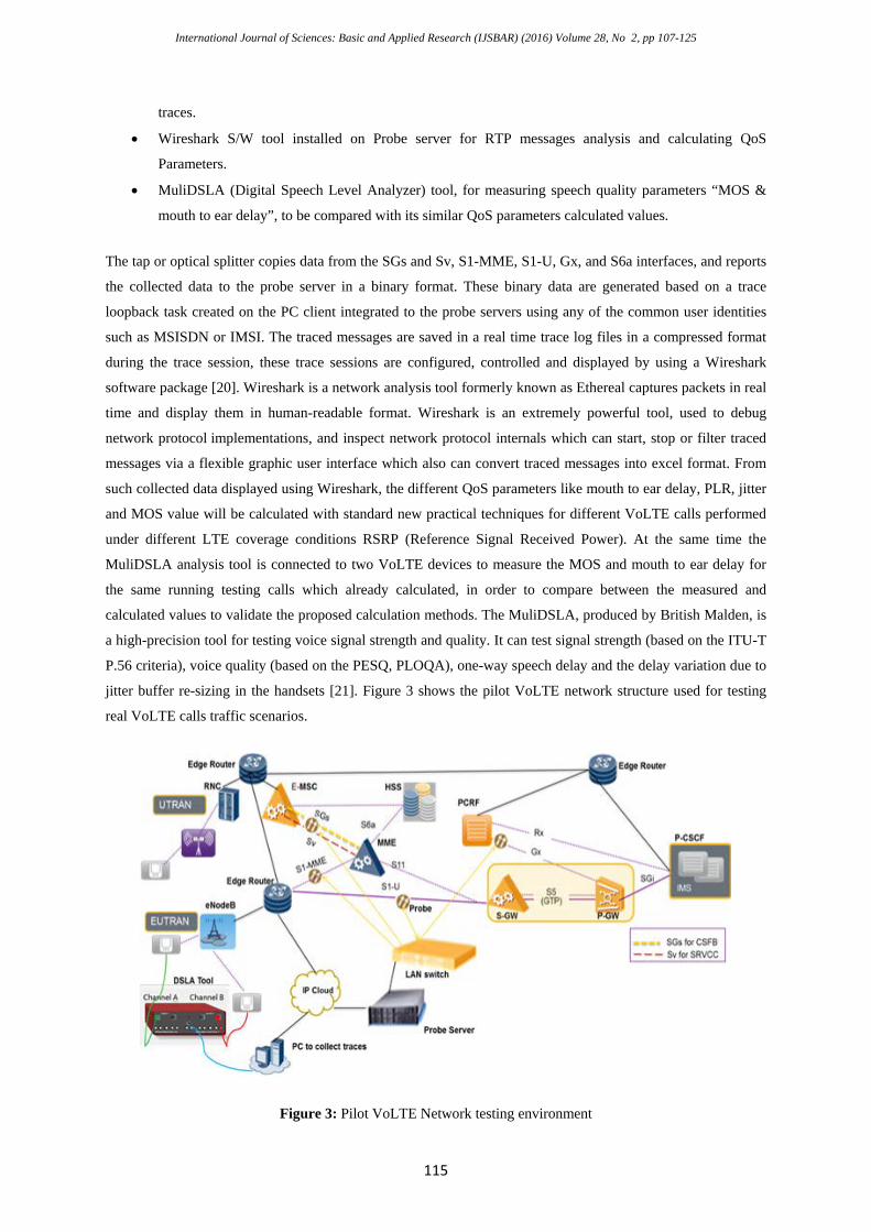
• Wireshark S/W tool installed on Probe server for RTP messages analysis and calculating QoS
Parameters.
• MuliDSLA (Digital Speech Level Analyzer) tool, for measuring speech quality parameters “MOS &
mouth to ear delay”, to be compared with its similar QoS parameters calculated values.
The tap or optical splitter copies data from the SGs and Sv, S1-MME, S1-U, Gx, and S6a interfaces, and reports
the collected data to the probe server in a binary format. These binary data are generated based on a trace
loopback task created on the PC client integrated to the probe servers using any of the common user identities
such as MSISDN or IMSI. The traced messages are saved in a real time trace log files in a compressed format
during the trace session, these trace sessions are configured, controlled and displayed by using a Wireshark
software package [20]. Wireshark is a network analysis tool formerly known as Ethereal captures packets in real
time and display them in human-readable format. Wireshark is an extremely powerful tool, used to debug
network protocol implementations, and inspect network protocol internals which can start, stop or filter traced
messages via a flexible graphic user interface which also can convert traced messages into excel format. From
such collected data displayed using Wireshark, the different QoS parameters like mouth to ear delay, PLR, jitter
and MOS value will be calculated with standard new practical techniques for different VoLTE calls performed
under different LTE coverage conditions RSRP (Reference Signal Received Power). At the same time the
MuliDSLA analysis tool is connected to two VoLTE devices to measure the MOS and mouth to ear delay for
the same running testing calls which already calculated, in order to compare between the measured and
calculated values to validate the proposed calculation methods. The MuliDSLA, produced by British Malden, is
a high-precision tool for testing voice signal strength and quality. It can test signal strength (based on the ITU-T
P.56 criteria), voice quality (based on the PESQ, PLOQA), one-way speech delay and the delay variation due to
jitter buffer re-sizing in the handsets [21]. Figure 3 shows the pilot VoLTE network structure used for testing
real VoLTE calls traffic scenarios.
Figure 3: Pilot VoLTE Network testing environment
International Journal of Sciences: Basic and Applied Research (IJSBAR) (2016) Volume 28, No 2, pp 107-125
116
The pilot network is configured in the following manner: - the eNodeB, P/S-GW , MME and PCRF which
represents the LTE domain, e-MSC represents the 3G CS domain, which enhanced to act as (SRVCC-IWF)
when SRVCC is required. These two domains were connected to IMS domain via Edge routers of IPBB cloud.
Each eNodeB is integrated to the EPC network with Giga links of 1Gbps bandwidth. With 15 MHz BW (Band
width), the eNodeB throughput is 90 Mbps for good coverage conditions, while it is 30Mbpbs for poor coverage
conditions. The signaling and traffic paths between the EPC and eNodeBs were separated using different VLAN
(Virtual Local Area Network) subnets. The IMS domain is divided into several zones for network security, the
access zone which includes the P-CSCF is isolated in a separate VLAN subnet to allow the access of the VoLTE
devices to the IMS network, while the services processing IMS servers (I-CSCF, S-CSCF and ATS) are
assigned to another VLAN subnet.
The UDP (User Datagram Protocol) is the default transport protocol used for real time audio traffic transport.
The voice packets are sent over RTP (Real-Time Protocol) streams, then the RTCP protocol (Real Time Control
Protocol) is used to calculate the mouth to ear delay, Packet lose rate, and Jitter, as the RTCP provides reception
quality statistics for the RTP data, these statistics are performed by the SR (sender report) which provide
transmission and reception statistics from participants that are active senders. And the RR (receive report)
provides reception statistics from participants that are not active senders [22]. Signaling and user plan interfaces
are taped with mirroring probes to collect all traffic messages to a lane switch which collects these traffic flows
and sends them to a probe server for processing and formatting to be easy for user interface collection via a
separate PC client to collect these traces in pcap format. The Signaling between EPC and eNodeB is carried
through GTP (GPRS Tunneling Protocol). GTP tunneling is located at both nodes (EPC, eNodeB) and it is
dynamically established between them to carry the EPS required bearers. For QoS guarantee, the PCRF
configured to provide full GBR (guaranteed bit Rate) bandwidth requirements provided form the P-CSCF via
the Rx interface for the VoLTE voice calls dedicated bearer with QCI=1 , to be delivered to the P-GW via the
Gx interface . For VoLTE signaling default bearer, the HSS is configured to provide uplink and downlink
bandwidths of 1024 kbps for the “ims” APN, all these bandwidths should be guaranteed while being transferred
via the IPBB (IP back bone) cloud. On the IPBB cloud transport network, each service traffic type is assigned a
specific bandwidth based on priority settings on the edge router to give the Signal/Voice services PQ (Priority
Queue) scheduling strategy, so the mandatory bandwidth is absolutely guaranteed for voice services. Bandwidth
shaping value for each service is estimated based on existing network usage. WFQ (Weighted fair scheduling)
with weight 1/5 factor will be assigned of remaining data services which will utilize the rest free bandwidth of
PQ queue. So there is no affect base on WFQ small weight value.
6. Mathematical Calculations for VoLTE QoS KPIs
The performance verification for the VoLTE network is considering the different QoS KPIs such as: MOS
values, mouth to ear delay, packet loss rate, and packets jitter as performance metrics. By inspecting the RTCP
VoLTE packets generated from real traffic scenarios , the different QoS KPIs will be calculated using novel
standard based methods which will be explained below:-
6.1 MOS Calculations for VoLTE calls
International Journal of Sciences: Basic and Applied Research (IJSBAR) (2016) Volume 28, No 2, pp 107-125
117
R = 100 – Ie – (95 - Ie) x Bpl Bpl + Ppl
(2)
>≤≤−−++
≤=
100;5.41000;)60(610*7035.01
0;1
RRRRR
RMOS (3)
VoLTE mouth to ear delay = Network delay + Encoding / decoding delay Compression/decompression delay
+Dejitter buffer delay (4)
The E-Model defined in [24] is used to calculate the MOS based on the R-factor. The R-factor called the rating
factor is used to measure the quality of the VoIP call based on various parameters like packet end to end delay,
PLR etc. In compliance with [23,24],the R value can be calculated using Eq. (2) , which is a simplified form of
the E-model considering only the effect of codecs and packet losses on the R factor value. The R-factor is
expressed as follows:-
Where Ie is the impairment caused due to packet losses in the network, Bpl is the packet-loss robustness factor,
and Ppl indicates the PLR. Ie and Bpl values are related to codecs bit rate. The MOS ranges from 1 to 5. The
value 1 indicates the poorest quality, and the value 5 indicates the best quality. An estimated MOS for the
conversational situation in the scale 1-5 can be obtained based on the R-factor using the following mapping
formula defined in [23]:
6.2 Mouth to Ear Delay Calculations for VoLTE calls
The VoLTE mouth to ear delay is one of the most important factors to be considered when measuring the
VoLTE QoS. It should be strictly maintained under reasonable limits and must be carefully monitored. The
equation used to calculate E2E delay is shown in [8]:
The Dejitter_buffer value is about 30ms practically, which depends on Mobile unit manufacturer, the whole
processing delay for the Mobile unit varies between 80 ms to 100 ms. The VoLTE mouth to ear delay could be
calculated by adding the network delay in addition to the mobile processing average time which almost 85ms.
To achieve a voice quality not worse than that of circuit switched voice, the mouse-to-ear delay for VoIP service
should be less than 250 ms [4]. After taking into account packet processing delay and propagation delay in the
core network of about 100 ms, the delay budget left for radio access network should be around 150 ms. We
further assume that both end-users are E-UTRAN users, then the tolerable delay for MAC scheduling and
buffering should be strictly within 80 ms. In the LTE system performance evaluation phase, 50 ms delay budget
is agreed as the simulation assumption [5, 17 ,30].
According to section 6.4.1 (SR: Sender Report RTCP Packet) in [22], the network E2E delay can be calculated
in the way as shown in Figure 4. The calculations depend on the NTP (Network Time Protocol) stamp for any
SR , that NTP time stamp is a 64 bit unsigned fixed-point number with the integer part in the first 32 bits which
is called MSW (Most Significant word) and the fractional part in the last 32 bits which is called LSW (least
significant word) . In some fields where a more compact representation is appropriate, only the middle 32 bits
International Journal of Sciences: Basic and Applied Research (IJSBAR) (2016) Volume 28, No 2, pp 107-125
118
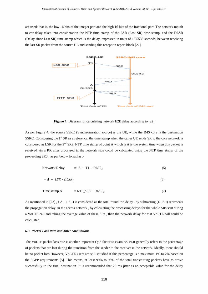
are used; that is, the low 16 bits of the integer part and the high 16 bits of the fractional part. The network mouth
to ear delay takes into consideration the NTP time stamp of the LSR (Last SR) time stamp, and the DLSR
(Delay since Last SR) time stamp which is the delay, expressed in units of 1/65536 seconds, between receiving
the last SR packet from the source UE and sending this reception report block [22].
Figure 4: Diagram for calculating network E2E delay according to [22]
As per Figure 4, the source SSRC (Synchronization source) is the UE, while the IMS core is the destination
SSRC. Considering the 1st SR as a reference, the time stamp when the caller UE sends SR to the core network is
considered as LSR for the 2nd SR2. NTP time stamp of point A which is A is the system time when this packet is
received via a RR after processed in the network side could be calculated using the NTP time stamp of the
proceeding SR3 , as per below formulas :-
Network Delay = A − T1 – DLSR2 (5)
= 𝐴𝐴 − 𝐿𝐿𝐿𝐿𝐿𝐿 –𝐷𝐷𝐿𝐿𝐿𝐿𝐿𝐿2 (6)
Time stamp A = NTP_SR3 – DLSR 3 (7)
As mentioned in [22] , ( A – LSR) is considered as the total round trip delay , by subtracting (DLSR) represents
the propagation delay in the access network , by calculating the processing delays for the whole SRs sent during
a VoLTE call and taking the average value of these SRs , then the network delay for that VoLTE call could be
calculated.
6.3 Packet Loss Rate and Jitter calculations
The VoLTE packet loss rate is another important QoS factor to examine. PLR generally refers to the percentage
of packets that are lost during the transition from the sender to the receiver in the network. Ideally, there should
be no packet loss However, VoLTE users are still satisfied if this percentage is a maximum 1% to 2% based on
the 3GPP requirements [5]. This means, at least 99% to 98% of the total transmitting packets have to arrive
successfully to the final destination. It is recommended that 25 ms jitter as an acceptable value for the delay
International Journal of Sciences: Basic and Applied Research (IJSBAR) (2016) Volume 28, No 2, pp 107-125
119
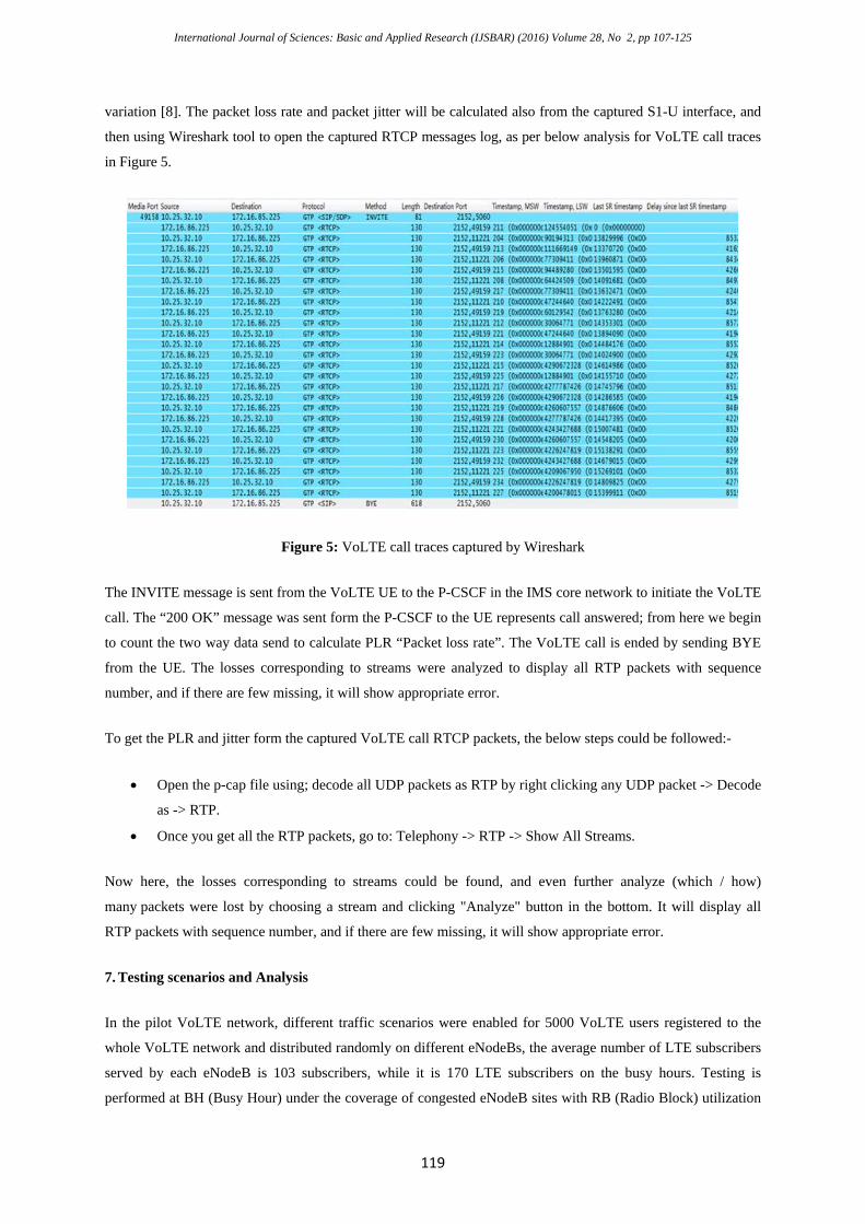
variation [8]. The packet loss rate and packet jitter will be calculated also from the captured S1-U interface, and
then using Wireshark tool to open the captured RTCP messages log, as per below analysis for VoLTE call traces
in Figure 5.
Figure 5: VoLTE call traces captured by Wireshark
The INVITE message is sent from the VoLTE UE to the P-CSCF in the IMS core network to initiate the VoLTE
call. The “200 OK” message was sent form the P-CSCF to the UE represents call answered; from here we begin
to count the two way data send to calculate PLR “Packet loss rate”. The VoLTE call is ended by sending BYE
from the UE. The losses corresponding to streams were analyzed to display all RTP packets with sequence
number, and if there are few missing, it will show appropriate error.
To get the PLR and jitter form the captured VoLTE call RTCP packets, the below steps could be followed:-
• Open the p-cap file using; decode all UDP packets as RTP by right clicking any UDP packet -> Decode
as -> RTP.
• Once you get all the RTP packets, go to: Telephony -> RTP -> Show All Streams.
Now here, the losses corresponding to streams could be found, and even further analyze (which / how)
many packets were lost by choosing a stream and clicking "Analyze" button in the bottom. It will display all
RTP packets with sequence number, and if there are few missing, it will show appropriate error.
7. Testing scenarios and Analysis
In the pilot VoLTE network, different traffic scenarios were enabled for 5000 VoLTE users registered to the
whole VoLTE network and distributed randomly on different eNodeBs, the average number of LTE subscribers
served by each eNodeB is 103 subscribers, while it is 170 LTE subscribers on the busy hours. Testing is
performed at BH (Busy Hour) under the coverage of congested eNodeB sites with RB (Radio Block) utilization

International Journal of Sciences: Basic and Applied Research (IJSBAR) (2016) Volume 28, No 2, pp 107-125
120
more than 99%. Multiple VoLTE calls with duration not less than 2 minutes duration were performed under
different LTE coverage conditions ranged from “-70dBm” to “- 85dBm” for good wireless conditions and
reached the range of “ -95dBm” to “-110 dBm” for bad coverage conditions . Different VoLTE calls were
performed on stationery situations and also while driving with different speeds starting from 20Km/h until
reached 100Km/h. Traces of random VoLTE calls were collected and analyzed. As performance metrics MSW,
LSW, LSR, and DLSR which are collected from the captured S1-u interface, were used to calculate the network
delay which will be added to 85ms to calculate the whole E2E delay, and then it is compared to the E2E delay
value collected by the MuliDSLA tool at the same testing conditions by considering a measurement period of 8s
duration (the optimum period for speech quality analysis).MuliDSLA reports the average; maximum and
minimum delay, and presents this information numerically and graphically. The MOS values are calculated
using the R factor calculated for the WB-AMR CODEC with bate rate 23.85 Kbps.
Fig 6 shows the packet loss rate values and packets jitter measured under different coverage conditions, where it
is clearly seen that PLR will be increased under poor wireless coverage conditions but due to applying proper
design values for QoS parameters, most of its values are less than 1%, and the packet jitter values increased
under poor coverage conditions but still under 25 ms.
Figure 6: VoLTE Jitter and packet loss rate under different poor wireless conditions
Comparing the calculated average of PLR obtained from the live VoLTE environment which is 0.0074 %, to the
results obtained by simulation done in [8] which was 0.0048%, it is clearly shows that even the VoLTE calls
performed under poor coverage conditions with real traffic scenarios and practical wireless environment, the
proper design of QoS parameters leads to a perfect system performance. By recording all the packet loss rates
values and inserting them into Eq. (2) as Ppl parameter and considering the standard values for Ie and Bpl for
the WB-AMR codec with 23.85 Kbps rate [24,25], to get the R factor value, which will be used in Eq. (3) to
calculate the MOS values for these calls. Figure 7 shows the relation of the calculated MOS values to the PLR
under bad coverage conditions and clearly indicated that the average MOS value is 3.91 which is higher than the
values collected by simulation done in [9,10]which reflects good voice quality although the testing calls were
performed under poor coverage conditions. And that value is matched with the conclusion in [11] as the MOS
values will be affected by the very bad wireless conditions which affected the overall average MOS values,
noting that if the MOS values under -120 dBm are excluded from the overall average value the result MOS
value will be higher than 3.95 which is near 4 even the testing was conducted within poor coverage range. When
International Journal of Sciences: Basic and Applied Research (IJSBAR) (2016) Volume 28, No 2, pp 107-125
121
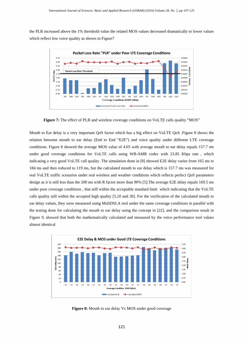
the PLR increased above the 1% threshold value the related MOS values decreased dramatically to lower values
which reflect low voice quality as shown in Figure7
Figure 7: The effect of PLR and wireless coverage conditions on VoLTE calls quality “MOS”
Mouth to Ear delay is a very important QoS factor which has a big effect on VoLTE QoS .Figure 8 shows the
relation between mouth to ear delay (End to End “E2E”) and voice quality under different LTE coverage
conditions. Figure 8 showed the average MOS value of 4.05 with average mouth to ear delay equals 157.7 ms
under good coverage conditions for VoLTE calls using WB-AMR codec with 23.85 Kbps rate , which
indicating a very good VoLTE call quality. The simulation done in [8] showed E2E delay varies from 165 ms to
184 ms and then reduced to 119 ms, but the calculated mouth to ear delay which is 157.7 ms was measured for
real VoLTE traffic scenarios under real wireless and weather conditions which reflects perfect QoS parameters
design as it is still less than the 200 ms with R factor more than 90% [5].The average E2E delay equals 169.5 ms
under poor coverage conditions , that still within the acceptable standard limit which indicating that the VoLTE
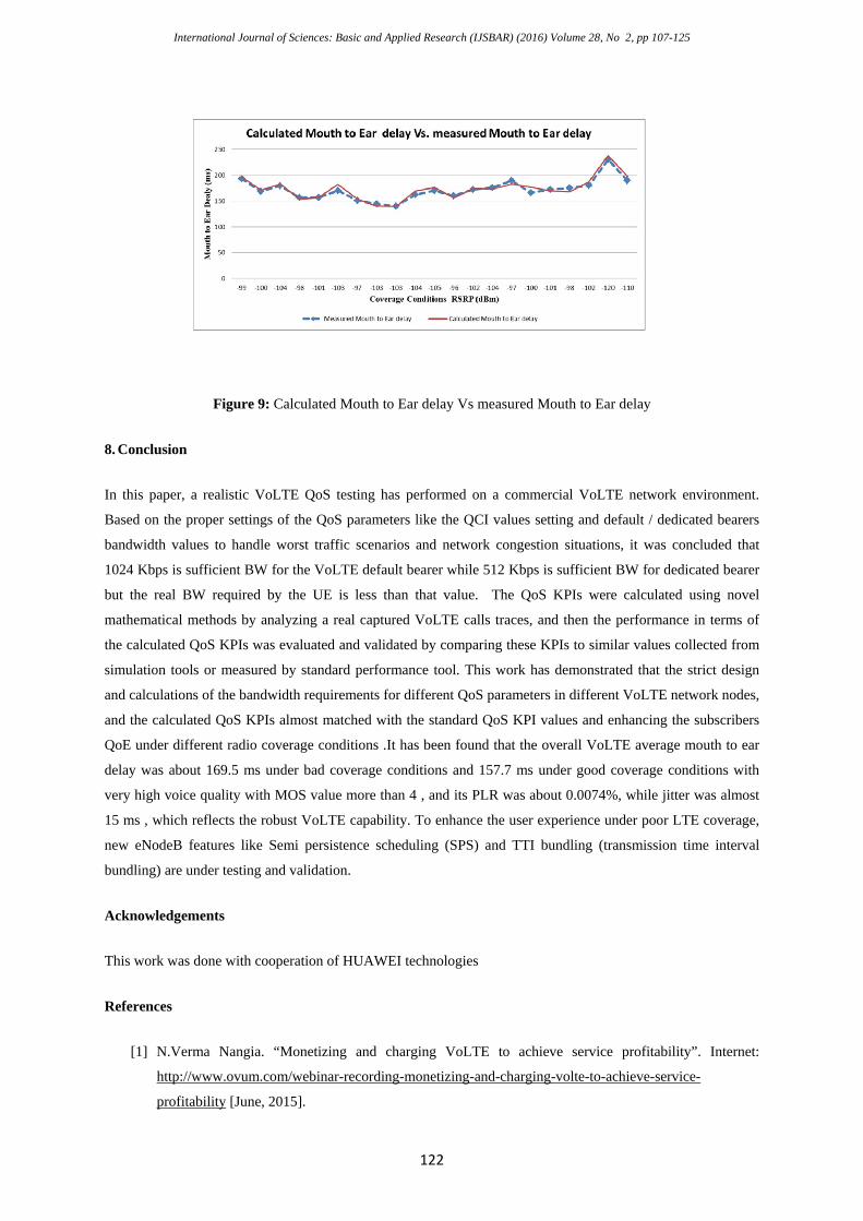
calls quality still within the accepted high quality [5,10 and 30]. For the verification of the calculated mouth to
ear delay values, they were measured using MuliDSLA tool under the same coverage conditions in parallel with
the testing done for calculating the mouth to ear delay using the concept in [22], and the comparison result in
Figure 9, showed that both the mathematically calculated and measured by the voice performance tool values
almost identical
Figure 8: Mouth to ear delay Vs MOS under good coverage
International Journal of Sciences: Basic and Applied Research (IJSBAR) (2016) Volume 28, No 2, pp 107-125
122
Figure 9: Calculated Mouth to Ear delay Vs measured Mouth to Ear delay
8. Conclusion
In this paper, a realistic VoLTE QoS testing has performed on a commercial VoLTE network environment.
Based on the proper settings of the QoS parameters like the QCI values setting and default / dedicated bearers
bandwidth values to handle worst traffic scenarios and network congestion situations, it was concluded that
1024 Kbps is sufficient BW for the VoLTE default bearer while 512 Kbps is sufficient BW for dedicated bearer
but the real BW required by the UE is less than that value. The QoS KPIs were calculated using novel
mathematical methods by analyzing a real captured VoLTE calls traces, and then the performance in terms of
the calculated QoS KPIs was evaluated and validated by comparing these KPIs to similar values collected from
simulation tools or measured by standard performance tool. This work has demonstrated that the strict design
and calculations of the bandwidth requirements for different QoS parameters in different VoLTE network nodes,
and the calculated QoS KPIs almost matched with the standard QoS KPI values and enhancing the subscribers
QoE under different radio coverage conditions .It has been found that the overall VoLTE average mouth to ear
delay was about 169.5 ms under bad coverage conditions and 157.7 ms under good coverage conditions with
very high voice quality with MOS value more than 4 , and its PLR was about 0.0074%, while jitter was almost
15 ms , which reflects the robust VoLTE capability. To enhance the user experience under poor LTE coverage,
new eNodeB features like Semi persistence scheduling (SPS) and TTI bundling (transmission time interval
bundling) are under testing and validation.
Acknowledgements
This work was done with cooperation of HUAWEI technologies
References
[1] N.Verma Nangia. “Monetizing and charging VoLTE to achieve service profitability”. Internet:
http://www.ovum.com/webinar-recording-monetizing-and-charging-volte-to-achieve-service-
profitability [June, 2015].
International Journal of Sciences: Basic and Applied Research (IJSBAR) (2016) Volume 28, No 2, pp 107-125
123
[2] 3GPP TS 22.228 V13.3.0 “Service requirements for the Internet Protocol (IP) Multimedia core network
Subsystem (IMS)”. Stage 1 (Release 13), June 2015.
[3] 3GPP TS 22.173 V14.1.0. “IP Multimedia Core Network Subsystem (IMS) Multimedia Telephony
Service and supplementary services”. Stage 1 (Release 14), March 2016.
[4] ITU-T, G.114 “General Recommendations on the transmission quality for an entire international
telephone connection one way transmission time”. February 2003.
[5] 3GPP TS 23.203 V13.7.0 “Policy and charging control architecture”. (Release 13), March 2016.
[6] M. Tabany, C.G. Guy “Performance Analysis and Deployment of VoLTE Mechanisms over 3GPP LTE-
based Networks”. The international Journal of Computer Science and Telecommunications, Volume 4,
Issue 10, October 2013
[7] Y. C. Sung , Y. H. Yang “Challenges from Voice-over-LTE to Video-over-LTE,” in Proc. Asia-Pacific
Network Operation and Management Symposium (APNOMS), 2014.
[8] M. Tabany, C.G.Guy “An End-to-End QoS Performance Evaluation of VoLTE in 4G E-UTRAN-based
Wireless Networks”, in: Proc. of the Tenth International Conference on Wireless and Mobile
Communications, 2014.
[9] A.Vizzarri, “Analysis of VoLTE End-To-End Quality of Service using OPNET”, IEEE, pp. 452-457 ,
2014.
[10] M.Anehill, M. Larsson, G. Strömberg, E. Parsons, “Validating voice over LTE end-to-end”. Internet:
https://www.ericsson.com/res/thecompany/docs/publications/ericsson_review/2012/er-volte
performance.pdf.
[11] K. Wac, G. Pinar; M. Gustarini, J. Marchanoff, “Smartphone users mobile networks quality, provision
and VoLTE intend: Six-month field study”. In Proc. World of Wireless, Mobile and Multimedia
Networks (WoWMoM), IEEE 16th International Symposium, 2015.
[12] A. E. Ko; S. Park; S. Kim; K. Son; H. Kim. “SIP amplification attack analysis and detection.
in VoLTE service network”. In Proc. International Conference on Information Networking (ICOIN)
,2016.
[13] J. Park; T. Jung; J. Kim; K. Yim. “Soliciting Unexpected Traffic Flows into VoLTE”. In Proc.
Innovative Mobile and Internet Services (IMIS) the 9th Ubiquitous Computing International
Conference, 2015.
[14] T.Henttonen, K.Aschan, J.Puttonen, N.Kolehmainen, P.Kela, M.Moisio, J.Ojala, “Performance of
VoIP with Mobility in UTRA Long Term Evolution”, IEEE, pp. 2492-2496, 2008.
International Journal of Sciences: Basic and Applied Research (IJSBAR) (2016) Volume 28, No 2, pp 107-125
124
[15] J.Janssen, D.Vleeschauwer, R.Windey, G.H. Petit, J. Leroy, “Delay bounds for voice over IP calls
transported over satellite access networks” , Journal on Mobile Networks and Applications (MONET),
Special issue on Satellite-Based Information Services, Volume 7, No. 1, pp. 79-89, January 2002.
[16] A.Vizzarri, “Analysis of VoIP Over LTE End-To-End Performances in Congested Scenarios”. In
Proc. of the 2nd International Conference Artificial Intelligence, Modelling and Simulation (AIMS),
2016
[17] Y. Fan, M. Kuusela, P. Lunden, M. Valkama, “Downlink VoIP support for evolved UTRA,
Wireless Communications and Networking”, IEEE, pp. 1933-1938 , 2008.
[18] T. Koshimizu, I. Tanaka, K.Nishida, “Improvement on the VoLTE (Voice over LTE) Domain
Handover with Operator’s vision”. Internet:
http://www.ieice.org/~wtc2012/Slides/Technical%20Sessions/TS-A3/TS-A3_4.pdf., [2012]
[19] Huawei Tech, “QoS Deployment Suggestion and IMS bandwidth calculation for VoLTE”, white
paper. Internet:http://support.huawei.com/hdx/hdx.do?docid=DOC1000175421&lang=en&path=PBI1-
21263365 [Dec.2015]
[20] “How to Use Wireshark to Capture, Filter and Inspect Packets”. Internet:
http://www.howtogeek.com/104278/how-to-use-wireshark-to-capture-filter-and-inspect-packets/
[21] Malden, “Digital Speech Level analyzer”. Internet: www.malden.co.uk/downloads/dslausrgd.pdf.
[22] H. Schulzrinne, S. Casner, R. Frederick, V. Jacobson, “RFC 3550 RTP: A Transport Protocol for Real-
Time Applications”. July 2003.
[23] ITU-T G.107, “The E-Model, a computational model for use in transmission planning”, June 2015.
[24] ITU-T G.113 Amendment1, “Transmission impairments due to speech processing”. March 2009.
[25] Huawei tech.”Voice Quality reporting, SE9S00QOSA00 QoS Assurance”. Internet:
http://support.huawei.com/hdx/hdx.do?docid=DOC1000176843&lang=en&path=PBI1-21262245 ,
May 2016.
[26] K. Anderson, S.A.Mostafa, R. UI-Islam, “Mobile VoIP User Experience in LTE”. Internet:
https://www.researchgate.net/publication/221081015_Mobile_VoIP_user_experience_in_LTE, 2011
[27] R.Sanyal, “Challenges in Interoperability and Roaming between LTE - Legacy core for Mobility
Management, Routing, Real Time Charging”. Internet:
https://www.researchgate.net/publication/228854874_Challenges_in_interoperability_and_roaming_be
tween_LTE-Legacy_core_for_mobility_management_routing_real_time_charging

International Journal of Sciences: Basic and Applied Research (IJSBAR) (2016) Volume 28, No 2, pp 107-125
125
[28] M.S. Hossen, “QoS Performance Evaluation of Video Conferencing over LTE”. M.A.Thesis. Blekinge
Institute of Technology. March 2012.
[29]Y.Ouyang, T.Yan, G. Wang, CrowdMi: “Scalable and Diagnosable Mobile Voice Quality Assessment
through Wireless Analytics”, Internet of things IEEE Magn. Vol. 2, pp. 287 – 294, 2015.
[30] T.Henttonen, K.Aschan, J.Puttonen, N.Kolehmainen, P.Kela, M.Moisio, J.Ojala, “Performance of
VoIP with Mobility in UTRA Long Term Evolution”, IEEE Magn., pp. 2492-2496, 2008.