design of regulated velocity flow assurance device … · design of regulated velocity flow...
TRANSCRIPT

DESIGN OF REGULATED VELOCITY FLOW ASSURANCE DEVICE FOR THE
PETROLEUM INDUSTRY
A Thesis
by
CHAITANYA YARDI
Submitted to the Office of Graduate Studies ofTexas A&M University
in partial fulfillment of the requirements for the degree of
MASTER OF SCIENCE
December 2004
Major Subject: Mechanical Engineering

DESIGN OF REGULATED VELOCITY FLOW ASSURANCE DEVICE FOR THE
PETROLEUM INDUSTRY
A Thesis
by
CHAITANYA YARDI
Submitted to Texas A&M Universityin partial fulfillment of the requirements
for the degree of
MASTER OF SCIENCE
Approved as to style and content by:
Reza Langari(Chair of Committee)
Alexander Parlos(Member)
Charles Bollfrass(Member)
Hamid Toliyat(Member)
Dennis O’Neal(Head of Department)
December 2004
Major Subject: Mechanical Engineering

iii
ABSTRACT
Design of Regulated Velocity Flow Assurance Device for the Petroleum Industry.
(December 2004)
Chaitanya Yardi, B.E., Gujarat University
Chair of Advisory Committee: Dr. Reza Langari
The petroleum industry faces problems in transportation of crude petroleum be-
cause of the deposition of paraffins, hydrates and asphaltenes on the insides of the
pipeline. These are conventionally removed using either chemical inhibitors or mechani-
cal devices, called pigs, which travel through the pipeline and mechanically scrape away
the deposits. These pigs are propelled by the pipeline product itself and hence travel at
the same velocity as the product. Research has indicated that cleaning would be better
if the pigs are traveling at a relatively constant velocity of around 70% of the product
velocity.
This research utilizes the concept of regulating the bypass flow velocity in order to
maintain the pig velocity. The bypass flow is regulated by the control unit based on
the feedback from the turbine flowmeter, which monitors the bypass flow. A motorized
butterfly valve is used for actually controlling the bypass flow.
In addition to cleaning, the proposed pig utilizes on-board electronics like accelerom-
eter and pressure transducers to store the data gathered during the pig run. This data
can then be analyzed and the condition of the pipeline predicted.
Thus, this research addresses the problem of designing a pig to maintain a constant
velocity in order to achieve better cleaning. It also helps gather elementary data that
can be used to predict the internal conditions in the pipe.

iv
To my parents

v
ACKNOWLEDGMENTS
I would like to thank my advisor, Dr. Reza Langari for his guidance and support
during my graduate studies at Texas A&M University. I will always remember his
willingness to spare time to meet me to discuss the project and most importantly his
looking into my welfare as well as those of his other students.
I would also like to thank Dr. Charles Bollfrass for providing me with an insight
into the conditions and problems faced by the oil industry and for his time and effort in
helping me complete my thesis. I am grateful to Dr. Alexander Parlos and Dr. Hamid
Toliyat for being on my committee and guiding me during the course of my thesis.
I would also like to express my keen gratitude to Mr. Jim Chitwood, of DeepStar
Projects, for providing me with an interesting real life problem to work on as my thesis.
He was also instrumental in providing me with data and giving me advice as and when
I needed it. I am also thankful to my family and friends who were with me whenever I
needed their support.

vi
TABLE OF CONTENTS
CHAPTER Page
I INTRODUCTION . . . . . . . . . . . . . . . . . . . . . . . . . . . . 1
A. Introduction . . . . . . . . . . . . . . . . . . . . . . . . . . . . 1
B. Problem Background . . . . . . . . . . . . . . . . . . . . . . . 2
C. Problem Statement . . . . . . . . . . . . . . . . . . . . . . . . 4
D. Research Objective . . . . . . . . . . . . . . . . . . . . . . . . 4
E. Research Scope . . . . . . . . . . . . . . . . . . . . . . . . . . 5
F. Conclusions . . . . . . . . . . . . . . . . . . . . . . . . . . . . 5
II BACKGROUND . . . . . . . . . . . . . . . . . . . . . . . . . . . . 7
A. Introduction . . . . . . . . . . . . . . . . . . . . . . . . . . . . 7
B. Petroleum Industry and Flow Assurance . . . . . . . . . . . . 7
C. Mechanical Pigs . . . . . . . . . . . . . . . . . . . . . . . . . . 11
1. Cleaning Pigs . . . . . . . . . . . . . . . . . . . . . . . . . 12
2. Smart Pigs . . . . . . . . . . . . . . . . . . . . . . . . . . 13
D. Past Research on Velocity Control Pigs . . . . . . . . . . . . . 15
E. Conclusion . . . . . . . . . . . . . . . . . . . . . . . . . . . . . 17
III DESIGN METHODOLOGY . . . . . . . . . . . . . . . . . . . . . . 18
A. Introduction . . . . . . . . . . . . . . . . . . . . . . . . . . . . 18
B. Problem Statement . . . . . . . . . . . . . . . . . . . . . . . . 18
C. Performance Objective . . . . . . . . . . . . . . . . . . . . . . 19
D. Design Requirements . . . . . . . . . . . . . . . . . . . . . . . 19
E. Design Constraints . . . . . . . . . . . . . . . . . . . . . . . . 20
F. Design Concept . . . . . . . . . . . . . . . . . . . . . . . . . . 20
G. Functional Requirements for Velocity Regulated Pig . . . . . . 21
1. Conditions Pig Needs to Satisfy . . . . . . . . . . . . . . 22
2. Pig Functions . . . . . . . . . . . . . . . . . . . . . . . . . 23
H. Various Possibilities Considered . . . . . . . . . . . . . . . . . 23
I. Conclusion . . . . . . . . . . . . . . . . . . . . . . . . . . . . . 34
IV CONCEPT DEVELOPMENT . . . . . . . . . . . . . . . . . . . . . 35
A. Introduction . . . . . . . . . . . . . . . . . . . . . . . . . . . . 35
B. Concept 1 : Governor Pig . . . . . . . . . . . . . . . . . . . . 35

vii
CHAPTER Page
C. Concept 2 : Pig Velocity Control Using Mechanical Braking . 39
D. Concept 3 : Bypass Control Using Motorized Butterfly Valve . 40
E. Conclusion . . . . . . . . . . . . . . . . . . . . . . . . . . . . . 45
V DESIGN OF PIG . . . . . . . . . . . . . . . . . . . . . . . . . . . . 46
A. Introduction . . . . . . . . . . . . . . . . . . . . . . . . . . . . 46
B. Basic Design Calculations . . . . . . . . . . . . . . . . . . . . 47
C. Design of Butterfly Valve . . . . . . . . . . . . . . . . . . . . . 51
1. Determining Valve Size . . . . . . . . . . . . . . . . . . . 51
2. Material Selection for Valve . . . . . . . . . . . . . . . . . 55
D. Design of Actuator for the Valve . . . . . . . . . . . . . . . . . 58
1. Type of Actuator . . . . . . . . . . . . . . . . . . . . . . 58
2. Torque Requirements of the Actuator . . . . . . . . . . . 59
3. Type of Motor . . . . . . . . . . . . . . . . . . . . . . . . 63
4. Final Specifications for the Actuator . . . . . . . . . . . . 66
E. Design of Power Source - Battery . . . . . . . . . . . . . . . . 66
F. Design of Worm Gear . . . . . . . . . . . . . . . . . . . . . . . 69
G. Design of Flowmeter . . . . . . . . . . . . . . . . . . . . . . . 70
1. Working of Turbine Flowmeter . . . . . . . . . . . . . . . 70
2. Specifying Flowmeter . . . . . . . . . . . . . . . . . . . . 71
3. Final Specifications . . . . . . . . . . . . . . . . . . . . . 72
H. Specification of the MEMs Accelerometer . . . . . . . . . . . . 73
I. MEMs Pressure Transducer . . . . . . . . . . . . . . . . . . . 75
J. Control Unit . . . . . . . . . . . . . . . . . . . . . . . . . . . . 76
K. Design of Pig Housing . . . . . . . . . . . . . . . . . . . . . . 81
1. Material of Construction . . . . . . . . . . . . . . . . . . 82
2. Calculating the Cylinder Thickness for Internal Pressure, 83
3. Calculating the Thickness for External Cylinder, . . . . . 84
4. Calculating Head Plate for Shell . . . . . . . . . . . . . . 85
5. Number of Bolts required at Flange Joints . . . . . . . . . 87
6. Calculating Bolt Size needed . . . . . . . . . . . . . . . . 88
VI PIG ASSEMBLY . . . . . . . . . . . . . . . . . . . . . . . . . . . . 90
A. Introduction . . . . . . . . . . . . . . . . . . . . . . . . . . . . 90
B. Assembly of the Regulated Velocity Semi-Intelligent Pig . . . . 90
C. Conclusion . . . . . . . . . . . . . . . . . . . . . . . . . . . . . 96
VII PROOF OF CONCEPT AND PROPOSED TESTING . . . . . . . 97

viii
CHAPTER Page
A. Introduction . . . . . . . . . . . . . . . . . . . . . . . . . . . . 97
B. Experimental Setup - Proof of Concept . . . . . . . . . . . . . 97
C. Actual Test Using Pig Prototype . . . . . . . . . . . . . . . . 102
D. Conclusion . . . . . . . . . . . . . . . . . . . . . . . . . . . . . 103
VIII CONCLUSION . . . . . . . . . . . . . . . . . . . . . . . . . . . . . 104
A. Conclusion . . . . . . . . . . . . . . . . . . . . . . . . . . . . . 104
B. Recommendations . . . . . . . . . . . . . . . . . . . . . . . . . 105
REFERENCES . . . . . . . . . . . . . . . . . . . . . . . . . . . . . . . . . . . . . 107
APPENDIX A . . . . . . . . . . . . . . . . . . . . . . . . . . . . . . . . . . . . . 110
VITA . . . . . . . . . . . . . . . . . . . . . . . . . . . . . . . . . . . . . . . . . . 119

ix
LIST OF TABLES
TABLE Page
I Design specifications . . . . . . . . . . . . . . . . . . . . . . . . . . . . . 20
II Comparison of various concepts . . . . . . . . . . . . . . . . . . . . . . . 44
III Design requirements . . . . . . . . . . . . . . . . . . . . . . . . . . . . . 47
IV Flow coefficients for various valve sizes . . . . . . . . . . . . . . . . . . . 52
V Seating and unseating torque requirement . . . . . . . . . . . . . . . . . 59
VI DC gearmotor specifications . . . . . . . . . . . . . . . . . . . . . . . . . 64
VII DC gear motor speed reduction ratio and torque outputs . . . . . . . . . 64
VIII Comparison of available batteries . . . . . . . . . . . . . . . . . . . . . . 68
IX Material comparison . . . . . . . . . . . . . . . . . . . . . . . . . . . . . 82

x
LIST OF FIGURES
FIGURE Page
1 Reduction in internal diameter of pipeline [1] . . . . . . . . . . . . . . . 8
2 Deposits removed from a pipeline [2] . . . . . . . . . . . . . . . . . . . . 9
3 Cleaning pig - polly pig [3] . . . . . . . . . . . . . . . . . . . . . . . . . . 12
4 Cleaning pig - steel mandrel pig [3] . . . . . . . . . . . . . . . . . . . . . 13
5 Smart pig using MFL to monitor pipeline condition [4] . . . . . . . . . . 15
6 Control logic when pig is stuck . . . . . . . . . . . . . . . . . . . . . . . 31
7 Control logic if pressure difference is large . . . . . . . . . . . . . . . . . 33
8 Bypass control using mechanical governor . . . . . . . . . . . . . . . . . 36
9 Another embodiment of mechanical governor . . . . . . . . . . . . . . . 38
10 Velocity control using braking . . . . . . . . . . . . . . . . . . . . . . . . 40
11 Bypass control using motorized butterfly valve . . . . . . . . . . . . . . 41
12 Worm wheel drive to connect motor to valve . . . . . . . . . . . . . . . . 61
13 Control logic flowchart . . . . . . . . . . . . . . . . . . . . . . . . . . . . 77
14 Control system for the regulated velocity pig . . . . . . . . . . . . . . . . 80
15 Proposed pig housing . . . . . . . . . . . . . . . . . . . . . . . . . . . . . 81
16 Pressures acting on the internal cylinder . . . . . . . . . . . . . . . . . . 83
17 Pressures acting on the external cylinder . . . . . . . . . . . . . . . . . . 84
18 Pressures acting on the head plate . . . . . . . . . . . . . . . . . . . . . 86
19 Value of C for plates welded with fillet weld . . . . . . . . . . . . . . . . 86

xi
FIGURE Page
20 Assembly of flowmeter and pig body 1 . . . . . . . . . . . . . . . . . . . 90
21 Assembly of annular bypass . . . . . . . . . . . . . . . . . . . . . . . . . 91
22 Sub-assembly of gear train and motor . . . . . . . . . . . . . . . . . . . 91
23 Complete sub-assembly of gear train and motor . . . . . . . . . . . . . . 92
24 Assembly of battery, control unit and gear train sub-assembly . . . . . . 92
25 Entire bypass assembly . . . . . . . . . . . . . . . . . . . . . . . . . . . . 93
26 Mounting of pig body 2 onto basic assembly . . . . . . . . . . . . . . . . 93
27 Complete pig housing . . . . . . . . . . . . . . . . . . . . . . . . . . . . 94
28 Pig assembly with transparent components . . . . . . . . . . . . . . . . . 94
29 Various components of the pig . . . . . . . . . . . . . . . . . . . . . . . . 95
30 Pig with scraper discs for cleaning . . . . . . . . . . . . . . . . . . . . . 95
31 Experimental test setup for proof of concept . . . . . . . . . . . . . . . . 98
32 Test setup for testing regulated velocity pig prototype . . . . . . . . . . 102
33 Pig housing - pig body 1 . . . . . . . . . . . . . . . . . . . . . . . . . . . 110
34 Pig housing - pig body 2 . . . . . . . . . . . . . . . . . . . . . . . . . . . 111
35 Pig housing - pig body 3 . . . . . . . . . . . . . . . . . . . . . . . . . . . 111
36 Turbine flowmeter . . . . . . . . . . . . . . . . . . . . . . . . . . . . . . 112
37 4” Butterfly valve . . . . . . . . . . . . . . . . . . . . . . . . . . . . . . . 113
38 DC gear motor . . . . . . . . . . . . . . . . . . . . . . . . . . . . . . . . 114
39 Electric battery pack . . . . . . . . . . . . . . . . . . . . . . . . . . . . . 114
40 Worm wheel . . . . . . . . . . . . . . . . . . . . . . . . . . . . . . . . . . 115
41 Worm gear . . . . . . . . . . . . . . . . . . . . . . . . . . . . . . . . . . 115

xii
FIGURE Page
42 Gear box to house worm wheel and worm gear . . . . . . . . . . . . . . . 116
43 Coupling to couple motor shaft and worm wheel . . . . . . . . . . . . . . 116
44 Pressure transducer . . . . . . . . . . . . . . . . . . . . . . . . . . . . . 117
45 Gasket for pig body 3 . . . . . . . . . . . . . . . . . . . . . . . . . . . . 117
46 Gasket for pig body 1,2 . . . . . . . . . . . . . . . . . . . . . . . . . . . 118
47 Scraper discs . . . . . . . . . . . . . . . . . . . . . . . . . . . . . . . . . 118

1
CHAPTER I
INTRODUCTION
A. Introduction
The major part of the energy available today is through hydrocarbon reserves, mainly
- oil and gas deposits. The development of offshore and onshore drilling technology has
allowed these reserves to be tapped. These hydrocarbon reservoirs are produced, drained
and transported over large distances through pipelines.
However there are problems in retrieving and transporting these resources from deep
under the earth to refineries, hundreds of miles away. Naturally occurring hydrocarbons
contain significant amounts of hydrates, asphaltenes, paraffins suspended in the oil.
These crystallize and precipitate onto the inner walls of the pipeline over time, thus
slowly choking the flow of the hydrocarbons itself. The problem is worsened under
certain thermodynamic conditions like sudden temperature or pressure changes. The
major concerns are:
1. Increased pumping costs because of reduction in internal diameter of the pipes
because of deposition of wax, asphaltenes and hydrates.
2. Restriction of flow of oil or gas as a result of increase the surface roughness.
3. The blockages caused by these deposits lead to loss of production.
4. Periodic repair, maintenance and sometimes even replacement is sometimes nec-
essary.
The journal model is IEEE Transactions on Automatic Control.

2
These problems are magnified in the offshore oil industry as the subsea temperatures
are not high enough to prevent the precipitation of these waxes.
The removal of these deposits is done by a variety of means, either by injection
of chemicals which help in dissolution of these deposits, or more commonly, by devices
called cleaning pigs. Pigs 1 are devices which move through the pipeline and mechanically
remove the deposits by scraping the inner walls of the pipeline . Pigs are used in the oil
industry to clean, scrape and remove paraffin, asphaltenes and hydrate deposits from
the pipelines. These pigs are propelled by the flow itself and hence travel at the flow
velocity.
B. Problem Background
The oil industry has observed that cleaning is better with special bypass pigs than with
ordinary pigs. The bypass pigs travel at a lower velocity than normal pigs as some of
the flow which propels the pig is bypassed. It was also noted that the flow through the
bypass carried away the deposits removed by the leading edge of the pig, thus prevented
accumulation of these deposits and hence reduced the chances of the pig getting stuck.
An oil consortium, DeepStar, sponsored research with Dr. Cem Serica which in-
vestigated the formation and accumulation of the cutting debris field ahead of a pig.
Dr. Serica described the impact of the debris field from his (simple) experiments and
went on to project that bypass fluids would minimize or prevent the accumulation of
the debris field by flushing the cuttings ahead of the pig in the bypass fluid.
A number of published research topics on the transportation of solids in a fluid
flow have indicated that that there is a maximum solids to liquid ratio that can be
transported as a slurry. If the percentage of solids to liquids in the flow exceeds about
1The devices are known as pigs because of the squealing noise they make whiletraversing the pipeline

3
40%, then solids start to bridge and blockages may form. Thus the annular bypass must
be so designed that the ratio of the amount of deposits removed and amount of bypass
fluid required, in total flow stream ahead of the pig remains around 40% with a nice
safety margin.
This has been estimated to being equivalent to bypassing about 30% of the net flow
in order to maintain a safe solids to liquids margin. Thus the pig velocity is reduced to
around 70% of the flow velocity. There is also a need to maintain the pig velocity fairly
constant as any variation in this is going to affect the flow through the bypass and hence
indirectly affect the solids to liquids ratio in the flow. This would be detrimental as it
would increase the possibility of the pig getting stuck. Thus it is imperative to have a
fairly constant pig velocity to have better performance and reduced chances of getting
stuck.
Another important point to be considered is that all pipelines require periodic in-
spection to monitor the internal conditions of the pipelines. Majority of inspections
are carried out using inspection pigs called ’smart’ pigs. These pigs use various tech-
niques like Magnetic flux leakage (MFL) and Ultrasonic to provide information regarding
pipeline condition. The basic parameters that need to be determined being corrosion,
pitting and cracking. Such smart pigs provide a standard for determining pipeline con-
dition, however they require specially designed pigs, which can be physically large and
heavy.A lot of research has been done in this field, particularly by Crouch, Anglisano
and Jaarah [5] or Willems and Barbian. [6].
The industry has shown interest in bridging the gap between the ’smart’ inspection
pigs and the ’dumb’ cleaning pigs. The possibility of combining some of the smart pig
capability into the cleaning pig would be extremely beneficial.

4
C. Problem Statement
The oil industry has estimated that the cleaning of pipelines would be more efficient at
slower speeds with a constant pig velocity of around 70% of the flow velocity.Improved
cleaning is possible in principle, if the velocity of the pig is regulated in real time. A
constant velocity pig would translate into
1. enhanced cleaning,
2. reduced pig runs,
3. better production,
4. lower chances of the pig getting stuck in the pipeline
5. reduced slugging effects.
D. Research Objective
The intent of this research was to apply conceptual thinking rather than configuration
thinking of the problem. The main goal was to understand the real need of the design
task, to identify the requirements, functions, constraints and critical parameters to the
problem.
The objective of this thesis is to develop a conceptual design for a pig that will meet
the requirements of cleaning the pipelines and also regulate its velocity and maintain it
at a certain percentage of the flow. It is also desired to keep the design simple, using
standard commercially available components, so as to keep the design economically
viable for extensive use.
Even though, maintaining the pig at constant velocity for better cleaning purposes
remains the primary objective of this research, adding some basic sensing capabilities to

5
make the cleaning pig a ’semi-intelligent’ pig will be the secondary motive. This would
enable the monitoring of the deposition of paraffins after analyzing the data gathered
by the ’semi-intelligent’ pig.
E. Research Scope
This research is focussed on developing a conceptual design to meet the above stated
problems and objectives. A range of designs were proposed and only the optimum design
which best met the requirement was further developed. The pig is designed for pipelines
carrying oil only, though it could be modified to meet the requirements of a gas pipeline
too, this research focusses solely on the pig traveling in oil pipelines.
Secondly, the design concentrates on the development of a mechanism to control the
velocity of the pig, and not on the design of the pig parameters, as they have already been
standardized. The building of a prototype of the pig and testing it in real conditions, is
out of scope for this research due to lack of financial support and funding.
Lastly, the design is limited to providing the components necessary to take basic
measurements for monitoring deposition conditions. The pig is designed to make full
use of the components, utilized for controlling the velocity of the pig, by continuously
gathering data and recording it. This data may then be used for analysis and monitoring
of the pipeline. It is out of scope of the research to actually carry out analysis of the
data gathered by the ’semi-intelligent’ pig.
F. Conclusions
The need to improve the current form of pigging and the benefits of a velocity regulated
cleaning pig is discussed in this chapter. The research scope and objective are clearly
stated and they determine the direction for this research - new ways to regulate the

6
speed of the cleaning pig.

7
CHAPTER II
BACKGROUND
A. Introduction
This chapter discusses the growth of the petroleum industry in the past century and
the problems faced by it. The major problem being sustaining the flow through the
pipelines and hence the growing importance of the term - Flow assurance. The various
types of deposits that restrict flow, the problems caused by them and the means of
removal are also described in this chapter. The key terms, mechanical pigs, cleaning
pigs and intelligent or smart pigs are defined and discussed in detail. The research done
on velocity regulated pigging is also described to give a background regarding this field.
B. Petroleum Industry and Flow Assurance
The petroleum industry boom began in the early years of the 20th century and by
1940’s several hundreds of miles of pipeline were transporting natural hydrocarbons
across the country. The abundance and size of oil deposits beneath the ocean floor and
the development of offshore drilling technology has allowed the offhore oil production to
become a very valuable resource to the industry.
There are problems, however, in the retrieval and transportation of these resources.
It was well known that natural hydrocarbons had paraffin in solution, but it was only
towards the 1950’s that the deposits in the pipelines started posing severe problems by
slowly choking the flow through them. It was important to prevent any disruption of oil
services and to ensure the availability of oil to all parts of the country. In short, these oil
pipelines, which carried crude and distilled products, are the lifeline of the United States
of America. Since a major part of these pipelines were either subsea or underground and

8
hence the removal of these deposits had to be done from inside the pipeline. Assuring
and maintaining flow of oil through the pipelines became important and the term ’Flow
Assurance’ was coined.
In addition to prevention of blockages by wax and asphaltene deposits, hydrate for-
mation, scaling and corrosion flow assurance was later expanded to include determining
pipe size, layout of pipes based on the local geography, pumping capacity and where
to locate the pumps, insulation needed or heating required and addressing problems
due to slugging. Flow assurance is now defined as, ”Flow Assurance includes all issues
important to maintaining the flow of oil and gas from the reservoir to the reception
facilities”
The major Flow Assurance concerns are reduction in internal diameter of the pipes
because of deposition of wax, asphaltenes, hydrates etc which results in increased pump-
ing costs. These deposits also increase the surface roughness which further restricts flow
of oil or gas. The blockages caused by these deposits lead to loss of production, periodic
repair and maintenance and sometimes even replacement. Deposition at the valves may
result in interference in valve operation and other instrumentation.
The extent to which deposits might choke a pipeline are shown in Figure 1 and
Figure 2.[1] [2]
Fig. 1. Reduction in internal diameter of pipeline [1]
9
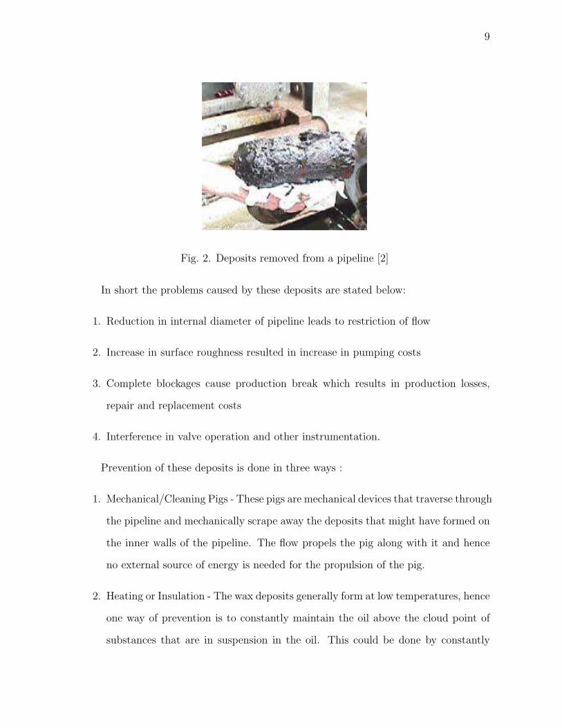
Fig. 2. Deposits removed from a pipeline [2]
In short the problems caused by these deposits are stated below:
1. Reduction in internal diameter of pipeline leads to restriction of flow
2. Increase in surface roughness resulted in increase in pumping costs
3. Complete blockages cause production break which results in production losses,
repair and replacement costs
4. Interference in valve operation and other instrumentation.
Prevention of these deposits is done in three ways :
1. Mechanical/Cleaning Pigs - These pigs are mechanical devices that traverse through
the pipeline and mechanically scrape away the deposits that might have formed on
the inner walls of the pipeline. The flow propels the pig along with it and hence
no external source of energy is needed for the propulsion of the pig.
2. Heating or Insulation - The wax deposits generally form at low temperatures, hence
one way of prevention is to constantly maintain the oil above the cloud point of
substances that are in suspension in the oil. This could be done by constantly

10
heating the oil or by insulating the oil to prevent it from falling below the cloud
point. Both these methods are generally too expensive to implement on a large
scale.
3. Chemicals - Special chemicals that inhibit or prevent the precipitation of these
deposits are injected into the pipeline along with the flow. These have been proved
to be effective and economic.
There are various kinds of deposits that might occur depending on the composition
of the crude oil and each has its own unique characteristic. They are listed below:
1. Wax - This blockage forms though out the entire pipeline and starts forming early
in the lifetime of the pipe. It is predicted and modeled using cloud point, pour
point and gel strength. It is currently prevented using pigs, insulation, heating
and chemicals. Chemical generally used is Wax inhibitor which is injected at the
tree or manifold at regular intervals of time.
2. Asphaltenes - These form especially at pressure drop locations like downhole, sub-
trees, separators etc and deposit all through the lifetime of the pipeline. As-
phaltenes may be determined and modeled using colloidal instability or solvent
titration or live oil depressurization. They are currently prevented using pigs or
chemicals like asphaltene inhibitor/asphaltene solvent that are injected at the bot-
tom hole and tree respectively.
3. Hydrates - Hydrates deposit through out the pipeline and form early on in life.
These are modeled and predicted using the hydrate stability curve and are kept in
check using pigs, heating of pipes or use of chemicals such as methanol or kinetic
inhibitor which are injected upstream and downstream of safety valve.

11
4. Sand - Sand deposition takes place especially at the base of risers, well heads,
valves or chokes. It is usually prevented using filters .
5. Scale - Scale formation starts late in life of the pipeline. This is determined using
Saturation index and is generally prevented using pigs or chemicals such as scale
inhibitor which are injected intermittently at the bottom hole.
C. Mechanical Pigs
The cheapest and most effective way to solve the problem was to design a device that
could travel through the pipeline, removing deposits and cleaning the pipeline while
traversing. This device, called a pig, is a snugly-fit plug which is propelled through the
pipeline to execute activities like cleaning or inspection. The term - Pig - got associated
with this device, because of the squealing noise it made, as it traversed through the
pipeline - and from then on the term stuck on. It is also referred to as the Pipeline
Inline Gauge (PIG) especially in context with the smart pigs.
Pigs are slightly over sized with respect to the pipeline they are supposed to traverse
in, so that they form a snug fitting plug in the pipe, thus completely sealing the pipeline
on both ends of the pig. They are propelled through the pipelines, usually using the
pipeline product such as oil or gas, as a propellent, though in some cases a different
propellent might be used for propulsion. Pigs are available in various shapes, sizes and
materials - they might be bullet-shaped, spherical or composed of an array of scraper
discs or propulsion cups. They also vary from simple polyurethane pigs, mandrel pigs,
batching pigs to more complex inspection or ’smart’ pigs.

12
1. Cleaning Pigs
The early cleaning pigs were simple in design and were just cylindrical bullet shaped
plugs and made of poly urethane foam. Their length was usually twice their diameter
for stability while traversing the pipeline so as to prevent the pig from flipping inside
the pipeline. These became popular by the name ”Polly Pigs”. To improve performance
of the pig, it was noticed that rotating pigs provided better cleaning - pigs were then
designed with helical ribs, which provided a slow rotational twist to the pig as it traversed
through the pipe - which resulted in improved cleaning.Figure 3 shows a polly pig.[3]
Fig. 3. Cleaning pig - polly pig [3]
As the demands of the oil industry grew, better cleaning methods were required.
The pigs were modified and spring loaded brushes and scrapers were mounted onto the
pig. These could scrape away even those stubborn deposits which could not be removed
using the polly pigs. The base of most of these pigs was still poly urethane, hence in one
cleaning run of around 30 miles, these would wear out and would be rendered useless.
The industry needed cleaning devices which could be used repeatedly for a number
of runs without the need to be discarded. The new pig, with a central steel bar was
developed, this had arrangement to attach scrapers, scraper discs and cups onto the
base. It was called the ”Steel Mandrel Pig”. This pig could be used for a variety of
pipeline sizes and after each run, only the scrapers and discs that had worn out needed

13
to be replaced while the basic pig could be reused. Figure 4 shows a steel mandrel pig.[3]
Fig. 4. Cleaning pig - steel mandrel pig [3]
Today, there exist pig trains, consisting of multiple pigs to meet the demands of
cleaning the pipe in as few pig runs as possible. These pig trains have several pigs joined
together with universal joints, so as to enable them to navigate through the pipeline
with ease.
2. Smart Pigs
The pipelines laid in the 1940s, started to develop leaks and ruptures in the mid 60s
and 70s. The cost of detecting a leak over a few hundred miles was both expensive and
time consuming. A major leak could lead to waste of oil/gas worth millions of dollars
and also create an environmental threat. There was need to develop preventive methods
rather than reactive ones. Thus the condition of the pipeline had to be monitored at
a regular intervals, so as to predict faults and failure before they occurred and to take
preventive steps to avoid a mishap. As most of these pipelines were either underground
or subsea, there was no way of monitoring them from outside. The only way to monitor
the condition of the pipeline was from inside the pipeline.
Hence, a new kind of pig was designed to meet this requirement. Instead of brushes
and scrapers, it had sensors mounted on it that recorded pipeline condition as the pig

14
traversed through the pipeline. This data was retrieved after the pig run was complete
and was analyzed for faults, cracks, corrosion and pitting in the pipeline. The pig data
revealed any type of anamolies in the pipeline and this helped prevent major leaks and
also helped in scheduling a plan for the repair or replacement of pipelines. This kind of
pig was called an Inspection pig or a Smart pig.
The smart pigs generally use either Magnetic Flux Leakage (MFL) or Ultrasonic
sound technology to predict corrosion, pitting or cracks in the pipelines.
Magnetic Flux Leakage Inspection system consists of three modules - a magnetizer
module, flux leakage sensors and discriminator sensors. The magnetizer module gener-
ates a magnetic flux within the pipeline by inducing a magnetic circuit into the pipeline
with the help of an on-board battery. If the pipeline has defects such as corrosion or
pitting, it causes localized flux leakage where corrosion or pitting exists. This change in
magnetic field due to flux leakage is detected by the flux leakage sensors which indicate
presence of pitting or corrosion. But it remains to be determined whether the defect
is internal or external. Another set of sensors, the discriminator sensors, only measure
the minimum depth at the inner surface of the pipe but cant measure external defects.
Thus using a combination of the flux leakage sensors and the discriminator sensors its
possible to pinpoint not only where in the pipeline the defects exist, but also whether
they are internal or external defects. [7]
Figure 5 shows a smart pig which uses MFL technology to detect corrosion, pitting
and cracking.[4]
The Ultrasonic Inspection system is similar to the MFL technique except that it
transmits an electrical pulse into the pipeline wall to measure pipe thickness. This
method requires a clean pipe for proper operation and as oil pipelines usually have some
paraffin buildup even after cleaning, this inspection method is preferred for gas pipelines
more than oil pipelines. [8]

15
Fig. 5. Smart pig using MFL to monitor pipeline condition [4]
In order to take accurate measurments, the smart pigs need to move at a slower
velocity than the flow velocity. Secondly, the velocity of the smart pigs needs to be
regulated and kept relatively constant so that the data collection is uniform throughout
the pipeline. The sampling rate of the sensors in the pig is constant, so if the pig velocity
varies then resolution of the measurements at different velocities is different and this
skews up the entire data collected. And this results in a distorted representation of the
pipeline profile. Hence it is important that the velocity of the smart pig be maintained
slower than the flow velocity and that it remains relatively constant throughout its run
through the pipeline.
D. Past Research on Velocity Control Pigs
The smart pig needs to maintain a slower velocity as compared to the regular production
flow velocity so as to take proper measurements in the pipeline. Initially, the flow
velocity itself was reduced by reducing the total production of the pipeline itself. Thus,
the velocity of the pig, which would still be traveling at the flow velocity, would be
reduced and the measurement data obtained would be more reliable and would be a
better representation of the actual condition in the pipeline.
This method worked well, but there were losses in production rate as the total
output volume of oil/gas was reduced drastically and the well could not be produced at

16
the optimum level. This resulted in large financial losses. Hence there grew a need to
have a pig which could maintain a slower pig velocity despite a higher production flow.
There has been some research into this problem and a few designs have been put
forward. Most of them use an annular space to by-pass some of the fluid flow. They
propose to control the velocity of the pig by controlling the amount of fluid flow through
the bypass.
The designs that have been put forward to solve this problem are discussed below :
In US patent No. 5208936, Campbell described the use of two plates with openings
in them in the annular by-pass of the pig at the two ends of the passageway. The rest
of the annular spaces between the pipeline and the pig is sealed, thus forcing all the
fluid flow to be through the annular by-pass only. One of the plates is then rotated in
relation to the other, which changes the fluid connection between the passageways. The
plate may be rotated with a stepper motor which is controlled by a comparator circuit
that compares the desired and actual pig speeds. Varying this degree of rotation, the
amount of fluid passing through the by-pass is regulated which in turn regulates the pig
speed. [9]
In US patent No. 6098231, Ian Smith, et al suggested the use of an hydraulic fluid
powered actuator to move a sleeve valve in order to control the flow through the annular
bypass. The valve comprises of a hollow cylindrical shell open at one end and closed at
the other with exit ports located circumferentially. The hydraulic actuator pushes the
sleeve outward, so that the exit ports are exposed allowing the fluid to pass through. The
sleeve can be retracted to close the exit ports and effectively close the bypass duct. A
range of intermediate bypass flows can be achieved by controlling the actuator between
these extreme positions. Thus by controlling the bypass flow, the pig velocity can be
regulated.
The hydraulic actuator is controlled by a hydraulic solenoid valve and an electrically

17
powered hydraulic pump. The actual speed of the pig is measured by odometer wheels,
it is then averaged over a predetermined time period and then compared to the desired
speed. The control system powers the actuator to either increase or decrease the opening
of the bypass to regulate the speed of the pig. The pig would carry its own power in the
form of battery pack. [10]
In US patent No. 4769598, Krieg et al. suggested the use of two hollow cylindrical
carriages both about half the size of the pipe diameter and coupled together. The
carriages are supported by rollers mounted on the outside and the annular passage
between the cylinders and the pipeline is sealed off by sealing discs. Hence the fluids in
the pipeline pass through the hollow carriages only. Two rotatable perforated discs are
mounted on the first carriage and the extent to which they are aligned determines the
bypass flow through the apparatus. Hence by regulating the bypass flow it is proposed
to regulate the speed of the pig. [11]
E. Conclusion
The major flow assurance problem faced by the petroleum industry is the deposition of
paraffins, asphaltenes, hydrates onto the inner walls of the pipelines. These are removed
either by chemicals or by mechanical devices called pigs. Mechanical pigs can be of
two types - simple cleaning pigs which scrape out the deposits or smart pigs which take
measurements about the internal condition of the pipeline. Smart pigs basically check
for corrosion or cracking.
Some research has been done in the field of velocity regulated pigs, but it is noticed
that most of the mechanisms proposed are complex and require highly specialized parts.
This would make the velocity regulated pig expensive and unsuitable for wide scale
application in the petroleum industry.

18
CHAPTER III
DESIGN METHODOLOGY
A. Introduction
The design methodology for this research is described in the chapter. The problem
faced, the performance desired, the design requirements and constraints are listed in
the following sections. The conditions the velocity regulated pig needs to satisfy and
the means to implement the requirements are noted. The various options available for
implementation are compared and discussed before the best possible option is chosen
for further investigation.
B. Problem Statement
Pigs are used in the oil industry to clean, scrape and remove paraffin, asphaltenes and
hydrate deposits from the pipelines. These pigs travel through the pipeline at varying
velocities. Improved cleaning is possible in principle, if the velocity of the pig is regulated
and maintained fairly constant. Industry research has estimated that cleaning is more
efficient at lower speeds with a relatively constant pig velocity of around 65-70% of the
flow velocity [1]. A by-pass may be provided in the pig, to allow the by-pass flow to
carry away the removed deposits to prevent them from accumulating in front of the
pig and potentially immobilizing the device. A constant velocity pig would translate
into enhanced cleaning, reduced pig runs, lower chances of the pig getting stuck in the
pipeline and reduced slugging effects.

19
C. Performance Objective
The objective of this proposal is to design and develop a prototype of a pig that can
regulate its velocity and maintain it at a certain percentage of the flow. It is also desired
to keep the design simple and standardized, in order to avoid the use of expensive sensors,
regulators and custom built parts to the extent possible. This is with the aim of keeping
the design economically viable for extensive use in the petroleum industry.
D. Design Requirements
1. The designed pig has to scrape the deposits like any other normal pig.
2. In addition, it has to maintain a constant velocity at a pre-specified level (approx-
imately 65-70% of the nominal flow velocity).
3. In the extreme case of the pig getting stuck, there should be an arrangement that
allows pressure to build up behind the pig to dislodge it.
4. When stuck, if the pressure difference across the pig is too large, the design should
allow for the release of some of the pressure.
5. In case it becomes necessary, the pig should accommodate back-flow pressure to
dislodge the pig.
The design specifications are listed in Table I.
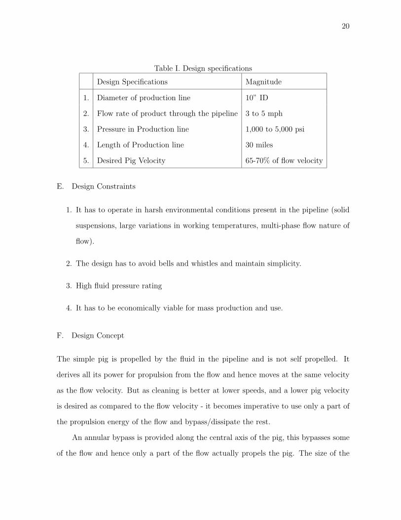
20
Table I. Design specifications
Design Specifications Magnitude
1. Diameter of production line 10” ID
2. Flow rate of product through the pipeline 3 to 5 mph
3. Pressure in Production line 1,000 to 5,000 psi
4. Length of Production line 30 miles
5. Desired Pig Velocity 65-70% of flow velocity
E. Design Constraints
1. It has to operate in harsh environmental conditions present in the pipeline (solid
suspensions, large variations in working temperatures, multi-phase flow nature of
flow).
2. The design has to avoid bells and whistles and maintain simplicity.
3. High fluid pressure rating
4. It has to be economically viable for mass production and use.
F. Design Concept
The simple pig is propelled by the fluid in the pipeline and is not self propelled. It
derives all its power for propulsion from the flow and hence moves at the same velocity
as the flow velocity. But as cleaning is better at lower speeds, and a lower pig velocity
is desired as compared to the flow velocity - it becomes imperative to use only a part of
the propulsion energy of the flow and bypass/dissipate the rest.
An annular bypass is provided along the central axis of the pig, this bypasses some
of the flow and hence only a part of the flow actually propels the pig. The size of the

21
annular passage can be designed so that the velocity of the pig is a certain percentage
of the flow velocity. Though the pig velocity is reduced, it will not maintain constant
velocity as the resistance faced by it in the form of deposits changes along the pipeline.
Thus in addition to having a bypass through the pig, some other means of control is
needed to keep it at regulated velocity.
The advantage of using a bypass flow in addition to reducing the pig velocity is that
the flow through the annular passage carries away the debris of the deposits removed
by the leading edge of the pig. This prevents the accumulation of debris in front of the
pig, and this reduces the chances of the pig getting stuck. This by itself results in better
cleaning, more reliability and lesser number of pigs getting stuck.
Hence, it is proposed to use the concept of actively controlling the flow through the
annular bypass to regulate the pig velocity.
G. Functional Requirements for Velocity Regulated Pig
There is need to regulate the velocity of the pig in order to keep it relatively constant
and this needs to be done actively and not just passively by designing the annular
bypass. To maintain the pig at a desired velocity, it is imperative to know the velocity
at which the pig is traveling. This velocity is then compared to the desired velocity and
an appropriate action is taken to get it back to the desired velocity.
The actual velocity of the pig might get lower than the desired velocity because
of increased resistance from wax deposits.In such a case, the cross sectional area of the
annular bypass should be reduced appropriately, so that there is a marginal increase in
the pressure behind the pig. This increase in pressure would help overcome the added
resistance faced by the pig. When the pig overcomes the resistance from the deposits, it
might start moving at a velocity that is greater than the desired velocity, if the bypass

22
still remains partially closed. Hence, in such circumstances the bypass must be opened
to allow more fluid to bypass and reduce the pressure behind the pig. This aids in
reducing the pig velocity. Thus to maintain the pig at a relatively constant velocity, it
is important to actively regulate the bypass fluid flow.
In addition, in the case of the pig getting stuck, the bypass should be shut off in
order to allow pressure to build behind the pig. This buildup of pressure would hopefully
be able to dislodge the pig. If this doesn’t work, another way of dislodging a stuck pig
is to back flow pressurize it. In this, the production is stopped so that there is no
flow pressure acting on the pig. A reverse pressure is then applied to the front portion
of the pig by pumping fluid back into the pipeline. This aids in dislodging the pig
from the accumulated deposits and moves the pig backward. The back pressure is then
discontinued and production is resumed. This forward and backward pressurizing has
been found to be useful in dislodging stuck pigs.
But if the pressure difference across the pig becomes too large, there is a possibility
of the pig or some component of the pig (ex. scrapers) disintegrating under the high
pressure. This disintegration would create debris in the pipeline which would be very
difficult to clean up. Hence, though its important to buildup pressure behind the pig
with the aim to dislodge the pig, too large a pressure could prove detrimental. Thus a
mechanism needs to be developed which would allow the release of pressure across the
pig, if the pressure difference crossed a certain threshold limit.
1. Conditions Pig Needs to Satisfy
The conditions the pig needs to satisfy are summarized below:
1. Control and regulate velocity of the pig
2. When stuck,close annular bypass

23
3. If difference in pressure is too large,a mechanism to release pressure
4. Allow back flow pressurizing to dislodge pig.
2. Pig Functions
The functions the pig needs to perform in order to satisfy the above requirements are
listed according to conditions :
1. To control and regulate the velocity of the pig
(a) Determine actual speed of the pig
(b) Regulate the velocity of the pig through some mechanism
2. To close the annular bypass when stuck
(a) Detect when the pig is stuck
(b) Close annular bypass to allow pressure buildup behind the pig
3. To release pressure when difference pressure is extreme
(a) Detect differences in pressure
(b) Open annular bypass to prevent damage to the pig and creation of debris in
the pipeline
4. To allow back flow pressurizing
(a) Prevent flow in the reverse direction
H. Various Possibilities Considered
A variety of options were studied and analyzed to determine which best fit the require-
ment for implementation with the pig. These are discussed for all the cases in brief:

24
1. To determine actual speed of the pig.
It is difficult to determine the velocity of the moving pig in the pipeline directly,
hence an approach to infer the velocity of pig was adopted. If the velocity of the
flow through the by-pass can be measured efficiently, then the velocity of the pig
can be determined as the bypass velocity is relative to the pig velocity. When the
pig is moving at the desired velocity of 70 % , the flow through the annular bypass
is 30% of the flow velocity. Now consider the case of the pig moving at 100% of the
flow velocity then there is no flow through the bypass as the pig itself is moving at
the flow velocity, hence the bypass velocity is zero. On the other extreme if the pig
gets completely stuck and the pig velocity is zero, the entire flow is through the
annular bypass and the bypass velocity is 100% of the flow velocity. Thus there
exists a inversely proportional relationship between the annular bypass velocity
and the pig velocity. And as its easier to measure flow through a passageway, the
bypass velocity will be used to determine the pig velocity.
The ways the flow through the annular bypass could be measured are :
(a) Differential pressure V-cone
A differential V cone could be placed in the bypass flow and the pressure drop
across the cone would indicate the flow rate through the bypass.
Disadvantages:
• difficult to automate and integrate into a control system
• fear of the cone getting clogged with debris of removed wax
(b) Ultrasonic flow measurement
Ultrasonic flow measurement uses the ’Transit Time Principle’, whereby op-
posite sensors are used to send and receive signals through the fluid flow. The
25
signal travels faster when moving with the flow stream rather than against the
flow stream. The difference between the two transit times is used to calculate
the flow rate.
Advantages :
• no moving parts, hence less maintenance required
• can measure wide range of flow rates
• no pressure loss during measurement
Disadvantages:
• expensive as compared to conventional methods
• inefficient for multi-phase flow, as air bubbles skew readings
• difficult to adapt to harsh working environment
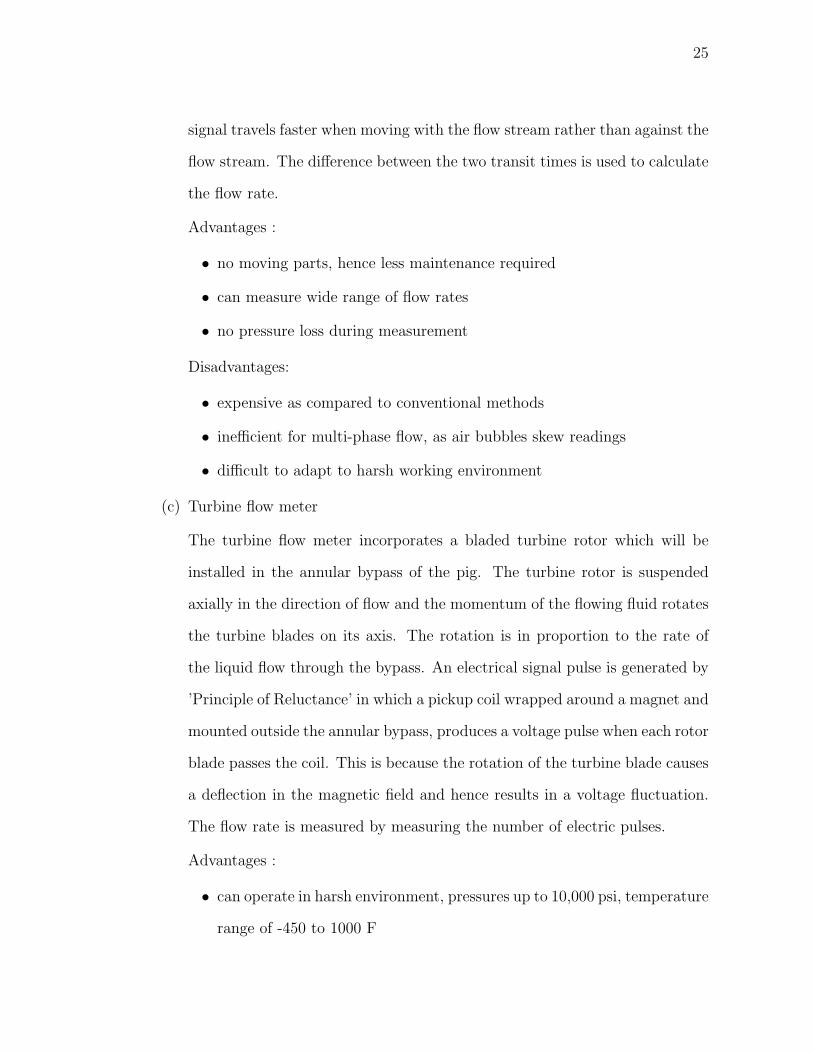
(c) Turbine flow meter
The turbine flow meter incorporates a bladed turbine rotor which will be
installed in the annular bypass of the pig. The turbine rotor is suspended
axially in the direction of flow and the momentum of the flowing fluid rotates
the turbine blades on its axis. The rotation is in proportion to the rate of
the liquid flow through the bypass. An electrical signal pulse is generated by
’Principle of Reluctance’ in which a pickup coil wrapped around a magnet and
mounted outside the annular bypass, produces a voltage pulse when each rotor
blade passes the coil. This is because the rotation of the turbine blade causes
a deflection in the magnetic field and hence results in a voltage fluctuation.
The flow rate is measured by measuring the number of electric pulses.
Advantages :
• can operate in harsh environment, pressures up to 10,000 psi, temperature
range of -450 to 1000 F

26
• high flow rates
• free standing, no mechanical coupling necessary to transmit rotation
• low maintenance cost
Disadvantages:
• loss of pressure
2. To regulate velocity of the pig through some mechanism
The velocity of the pig may be regulated in basically two ways - one would be to
control the flow through the annular bypass and the second would be to use some
braking mechanism to reduce the speed of the pig.
The concept of controlling by-pass flow to control pig velocity has been studied in
earlier studies. The annular bypass is designed to allow 30% of the flow to pass
through, this allows the pig to move at 70% of the flow velocity when it is not
facing resistance from wax deposits.
When the pig faces resistance, the bypass needs to be appropriately closed in order
to increase the pressure difference across the pig so that the pig is able to overcome
the resistance and yet continue with the desired velocity.
The concept of using braking to control pig velocity is being proposed in this work.
The annular bypass in this case would be designed to allow about 20% of the flow
to pass through, this would increase the pig flow velocity to 80% - about 10%
above the desired velocity.
The pig would then employ necessary braking as and when appropriate to reduce
the pig velocity to the desired velocity.
The ways the velocity of the pig might be regulated are discussed below :

27
(a) Bellows
The bellows would be used as a braking device whenever the pig speed rose
above the desired value. Normally the bellow would be deflated but when the
pig speed crosses the set limit, it would be inflated either by the fluid in the
pipeline itself or by other means. This inflated bellow would then be designed
to push against the pipeline and increase the frictional force on the pig. This
increase in friction force would lower the velocity of the pig. The bellow would
be drained when the pig velocity is again within acceptable limits.
i. Passive inflation The bellow would be inflated and drained using the
pressure of the fluid flow itself as and when necessary. It would be the
pressure of the fluid that would push the bellow against the pipeline, thus
increasing the frictional force.
ii. Active inflation In this case, the bellow would still be inflated using the
fluid in the pipeline, but an active measure to compress the bellow is
utilized so that it exerts a larger pressure on the pipeline walls. This
would aid in higher frictional forces and better and larger control over
the velocity of the pig.
Advantages :
• no power requirements
• low cost
Disadvantages:
• deflation/drainage of bellow is passive and cannot be controlled
• effectiveness, reliability not proven
• would require an operating valve to control flow into the bellow, thus
needing complex mechanical linkages

28
(b) Braking
This is another variation of the bellow idea. The concept of braking can be
applied in the literal case for reducing the pig velocity. The idea emerged
from the studying the working of the mechanical shoe brake and the ball
governor.
In the mechanical shoe brake, the stationary shoes are lined with braking
material and expand outward into the rotating drum when activated, this
increases the frictional forces and reduces the speed.
The same concept is to be used here, the only difference being instead of the
drum rotating and the shoes expanding, we have a combination of rotational
and linear motions for the brake pads.
The ball governor provided the concept of activating the brakes. The rotating
brake pads act as weights of a Watt governor and as the rotation speed
increases, they are pushed outward because of the centrifugal force. Springs
may be designed to counter the centrifugal force.
The annular bypass would be so designed so as to allow only 20% of the
flow velocity and hence the pig would travel at a higher velocity than desired.
The shoes with braking liners would be activated as and when the pig velocity
exceeds the allowable limit.
Advantages :
• no power requirements
• low cost
• effectiveness, reliability proven in a different field of application
Disadvantages:
• less control over the magnitude of braking

29
(c) Valves
The concept of controlling the bypass velocity to control the velocity of the
pig, can be implemented using valves. The valve is placed in the annular
bypass and in the path of the fluid flow and it may be opened or closed to
regulate the bypass velocity. If the pig is slowing down the valve needs to
close, so that sufficient pressure can be built up behind the pig which will
overcome the resistance posed by the wax deposits and maintain the pig at
the desired velocity.
A variety of valves may be used for this purpose like, flapper valve, gate valve
and butterfly valve. The gate valve is not suitable for this type of operation
due to severe space restrictions. The flapper valve too, requires high torque
requirements for its operations and hence needs to be ruled out. The butterfly
valve best suits the requirements amongst the valves.
Advantages :
• good throttling device
• compact, lower weight, lower cost
• standard equipment and is widely used
• effectiveness, reliability already proven
• if fail close, can act as check valve and allow back flow to help dislodge
the pig
• simple to integrate and implement
• excellent rangeability from 30:1 to 100:1
Disadvantages:
• power necessary for means of activation
• increase in cost

30
3. To determine if the Pig is stuck
It is important to be able to distinguish whether the pig is stuck or not, as the
control system depends on this input to close the valve in the annular bypass to
increase the pressure behind the pig in order to dislodge it.
(a) Accelerometer The accelerometer can be used effectively to give an indication
whether the pig is moving or stationary by monitoring the output. If the pig
is going at a uniform velocity, theoretically the acclerometer should not show
a reading, but in this particular case, as the pig is bouncing and scraping its
way through the pipe the accelerometer will show some activity.
When the pig is completely stuck, we might expect some chattering in the
output of the accelerometer as the output might not be completely zero,
because the pig may vibrate. The vibrations could be possible as the pig
is facing a resistance from the wax and at the same time the fluid pressure
behind the pig is trying to overcome this resistance.
Thus a minimum threshold needs to be determined for the accelerometer
output, in order to conclusively say whether the pig is stuck or not. This
would be determined only after conducting a few experimental test runs.
(b) Odometric wheels Odometeric wheels have long been used with pigs to mea-
sure distance traveled and also to get the velocity profile. They are generally
spring loaded and press against the pipeline wall, the rotation of the wheels is
then interpreted to measure the distance traveled by the pig. These are stan-
dard components and could be used to determine whether the pig is moving
or whether its stuck.
It might be possible to get erroneous data if the wheel stops rotating because
its lost contact with the pipeline or it gets jammed because of wax deposits.

31
One way to overcome it would be to have input from multiple odometric
wheels.
4. To close annular bypass to allow buildup of pressure
In the case the pig gets stuck, it is necessary to use 100% of the fluid power available
instead of just the 70% that is utilized in the normal functioning of the pig. In
order to use the other 30% of the flow which is being bypassed, it is imperative
to close the annular bypass completely and allow the pressure to buildup behind
the pig. The increase in pressure behind the pig should be able to overcome the
additional resistance generated by the accumulation of the wax deposits.
The control logic that would be the basis of this closing of the annular bypass is
illustrated in Figure 6.
Fig. 6. Control logic when pig is stuck
5. Detect differential pressure and open valve to prevent large buildup of pressures
In the extreme case of the pig getting stuck and the buildup of pressure not be-
ing able to dislodge the pig, there exists a danger of an extremely large pressure
difference across the pig. Some parts of the pig, especially the scraper discs might

32
collapse and fall apart under this large pressure differential. Any such fragmen-
tation or crumbling is undesirable as it creates debris in the pipeline, which may
cause problems in risers and may interfere with the operation of pipeline equipment
like valves, pumps etc.
In order to avoid such a situation, it is important to buildup pressure behind the
pig to dislodge it, but it is more imperative to restrict the pressure differential to
safe and allowable limits. Thus the differential pressure across the pig needs to be
measured and kept in control.
(a) This differential pressure could be measured using a pressure transducer which
could be incorporated into the pig body and if a valve is being used, it could
detect the pressure across the valve. The MEMS pressure transducers are
ideally suited for such applications.
Advantages of pressure transducer
• easy to integrate into control system
• MEMS pressure transducers readily available
• small size and weight
Disadvantages of pressure transducer
• relatively more expensive
• would need thermal insulation against variations in temperatures
Based on the input from the pressure transducer, the control system would
open the valve in the annular bypass to release some of the pressure in order
to prevent any damage to the pig. Once the pressure is drained to acceptable
limits, the control system would close the valve again. This complete opening
and closing of the valve would override the normal throttling operation of the

33
valve.
The control system schematic for the above control logic is shown in Figure
7.
Fig. 7. Control logic if pressure difference is large
(b) Another alternative to the above problem is to design a safety valve which
would control a separate bypass connecting the front and the tail end of the
pig. The spring in the spring loaded safety valve would be designed such that
if the pressure across the pig crossed a certain value the safety valve would
open and allow the pressure to drain till the pressure differential was within
limits.
Advantages of using spring loaded safety valve
• Eliminates use of expensive sensors
• Simpler control system and logic
• Proven reliability and usage
6. Allow back flow pressurizing
In the extreme case, if the pig is unable to dislodge itself even after sufficient
buildup of pressure - back flow pressurizing tactic is generally used. In this, the
flow behind the pig is stopped and a reverse flow or back flow is applied. This flow

34
acts on the front end of the pig instead of the back and tries to push the pig in
the reverse direction. After a while, this back flow is stopped and the normal flow
resumed. This procedure is repeated with the aim of trying to dislodge the pig.
Thus is it important that the mechanism used for controlling the bypass is bubble
tight shutoff in both directions. If a valve is used to control the bypass, it would
offer this bi-directional shutoff.
I. Conclusion
A variety of options to meet the various functional requirements of the pig are discussed.
It is proposed to use a turbine flowmeter to indirectly measure the velocity of the pig, the
use of an accelerometer to determine whether the pig is completely stuck and preventing
buildup of large differential pressure across the pig using a safety valve or detecting
it using a MEMs pressure transducer. Two concepts for actually regulating the pig
velocity were discussed - concept of controlling the bypass flow velocity and the concept
of braking. Since neither had any obvious advantages over the other, it was decided to
investigate the concepts further in the following chapter and then finalize on one design
concept.

35
CHAPTER IV
CONCEPT DEVELOPMENT
A. Introduction
Now that the requirements for the pig have been properly identified and defined, it is
necessary to develop different strategies to solve the problem. In this chapter three
different design strategies are presented to tackle the problem of a regulated velocity
cleaning pig. These different approaches are then compared and evaluated and the
actual design would be based on the approach that best solves the problem.
B. Concept 1 : Governor Pig
As simplicity and cost were desired, the first approach was not to use any kind of sensors
or actuators in the pig, as it would make the pig expensive. Thus, the aim was to utilize
the energy of the fluid flow for all kinds of measurements and actuator mechanisms.
Instead of measuring the speed of the pig directly, it was measured indirectly and
regulated by controlling the flow through the annular bypass, it was also decided to use
completely mechanical means to control the bypass. The energy required for this system
of mechanical links would need to be derived from the flow itself. Thus removing the
need for an external source of power. A turbine flow meter is placed in the annular
bypass flow stream, this generates both the power required and also gives an indication
of the velocity of the pig. To control the bypass flow completely mechanically using a
valve, it is necessary that the rotational motion of the turbine flow meter be converted
into a linear motion to operate the gate valve.
After looking at various options, the idea of a Watt governor seemed perfect for
this application. The ball governor would be located outside the annular bypass and

36
the rotational motion of the turbine flow meter would be transferred to the governor
using a set of bevel gears. As the pig starts slowing down, the flow velocity through the
bypass increases and this in turn increases the rotation of the turbine flow meter. This
increased rotational energy is then transferred to the governor and the centrifugal force
pushes the balls outward resulting in the lifting the sleeve of the governor.
The linear motion of the governor sleeve is directly proportional to the change in
rotational velocity of the turbine flow meter. And the turbine flow meter is in turn
directly proportional to the flow velocity through the bypass. This linear motion of
the governor sleeve is utilized for the opening and closing of the gate valve. Hence its
possible to have a control system built into the mechanical system itself, which opens
and closes the gate valve. This removes the need for external control logic, external
power and hence is very economical.
The concept is illustrated below with the help of a simple diagram in Figure 8.
Fig. 8. Bypass control using mechanical governor
The design would be dependent on the weight of the governor balls, as they are

37
the crux of the design. The change in rotational velocity of the turbine flow meter is
figured out from the possible change in flow velocity through the bypass. The balls are
designed for weight that would lift the sleeve through the desired distance using the
power available through the turbine flow meter.
The governor balls need to be heavy enough so that they can lift the sleeve a
specified distance in order to actuate the valve and should also be able to overcome the
friction in the sleeve and the valve. But heavier the balls, the more difficult it is for the
turbine flow meter to power it, as the flow meter can only provide a certain amount of
rotational power that it derives from the flow through the bypass.
Again, with different flow rates in different pipelines, the rotational power supplied
by the turbine flow meter to the governor would vary. Hence, the amount of sleeve move-
ment for a set of governor balls would vary for different flow rates. Thus, a particular
set of governor balls, could only be used for a certain range of bypass flow. A series of
pigs with a range of governor ball weights needs to be developed to address the entire
spectrum of the pipeline flows.
Another problem with the current embodiment of the design, is the severe space
restrictions on the size of the governor. The annular bypass is calculated to be of 5.5-6”
diameter [in a 10” diameter pipeline and for a 8” diameter pig body] in order to allow
a bypass of 30-35%. Thus, there is just over an inch of space left, to try and fit in the
governor.
Hence, other embodiments of the governor pig idea were discussed, one of the em-
bodiment is shown in Figure 9.
But even this didn’t give substantial advantage as the travel of the governor balls
was severely restricted. Alternatives like high density materials were considered in order
to give substantial weight to the governor balls and yet keep them compact. But none
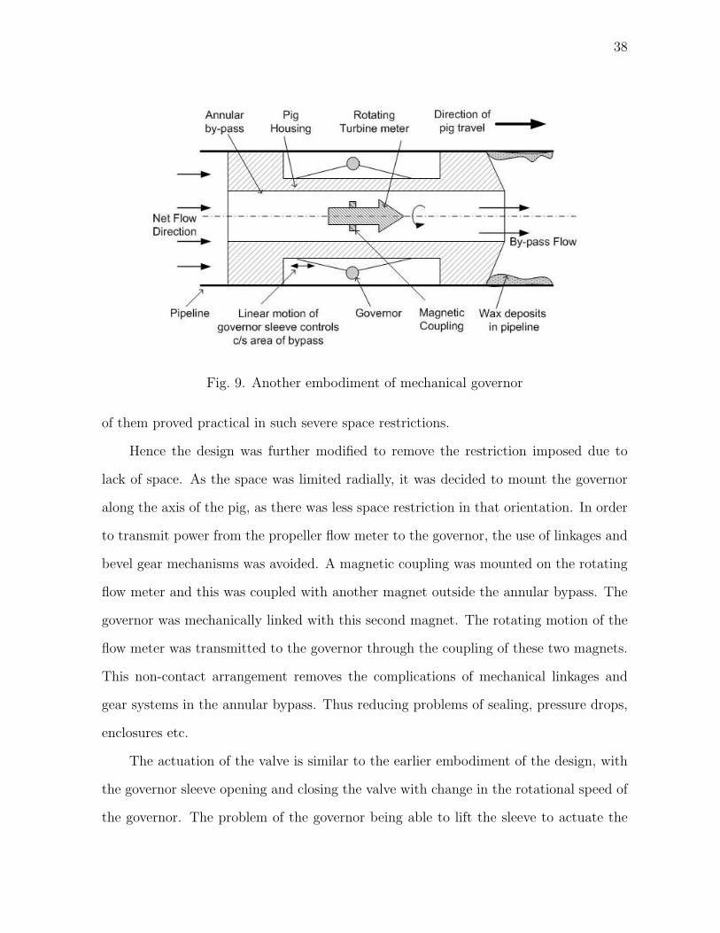
38
Fig. 9. Another embodiment of mechanical governor
of them proved practical in such severe space restrictions.
Hence the design was further modified to remove the restriction imposed due to
lack of space. As the space was limited radially, it was decided to mount the governor
along the axis of the pig, as there was less space restriction in that orientation. In order
to transmit power from the propeller flow meter to the governor, the use of linkages and
bevel gear mechanisms was avoided. A magnetic coupling was mounted on the rotating
flow meter and this was coupled with another magnet outside the annular bypass. The
governor was mechanically linked with this second magnet. The rotating motion of the
flow meter was transmitted to the governor through the coupling of these two magnets.
This non-contact arrangement removes the complications of mechanical linkages and
gear systems in the annular bypass. Thus reducing problems of sealing, pressure drops,
enclosures etc.
The actuation of the valve is similar to the earlier embodiment of the design, with
the governor sleeve opening and closing the valve with change in the rotational speed of
the governor. The problem of the governor being able to lift the sleeve to actuate the

39
valve still remains uncertain.
C. Concept 2 : Pig Velocity Control Using Mechanical Braking
In the second concept, instead of using the bypass flow to control the velocity of the
pig, we use the concept of braking to regulate the pig velocity. The annular bypass is
sized such that the pig has a higher velocity than desired, and then the pig velocity is
regulated by using mechanical brakes whenever necessary.
This design again uses the propeller type flow meter to measure the pig velocity
indirectly by measuring the flow velocity through the bypass. The governor idea is
further modified and the governor balls are replaced with brake pads mounted on springs.
As the bypass flow increases the rotational speed of the propeller meter increases, this
motion is transferred to a sleeve outside the annular bypass by the magnetic coupling.
The brake pads are mounted with springs on this rotating sleeve. As the rotational
speed increases, the rotating brake pads act like governor balls and move outward due
to centrifugal force by overcoming the spring force. This then acts like a mechanical
shoe brake, with the brake pads brushing against the inner pipe walls and thus reducing
the speed. When the speed is reduced to desirable limits, the spring is designed, such
that the spring force exceeds the centrifugal force and brake pads are withdrawn and
lose contact with the inner pipe walls. This is illustrated in Figure 10.
The major problem with this otherwise plain and simple design is that, the brakes
are activated when the flow through the bypass is high. But bypass flow velocity is high
when the pig velocity is lower than the desired velocity. Hence instead of increasing the
velocity of the pig, this design actually decreases it by further applying brakes.
This design basically uses the centrifugal force to overcome the spring force and

40
Fig. 10. Velocity control using braking
activate the brakes, and the centrifugal force is going to be maximum when the flow
through by the bypass is high. While we need just the opposite, some mechanism which
would pull in the brakes when the centrifugal force is high and push the brakes out with
the help of the spring force.
A variety of mechanical linkages and mechanisms were analyzed in order to figure
out a way to implement the above mentioned requirement. Though it is possible to
implement it, the device loses its basic advantage of being a simple, inexpensive device.
D. Concept 3 : Bypass Control Using Motorized Butterfly Valve
After looking at the above mentioned concepts, it becomes evident that it is difficult to
implement a device without the use of some basic actuators, sensors or power. Thus,
it was decided to design a pig with standard components and some basic controls. Ex-
pensive and custom built components were to be avoided as far as possible, to keep the
design simple and inexpensive.
This conceptual design also uses the flow meter to infer the velocity of the pig,

41
instead of some expensive ultrasonic velocity measurement. The inferred pig velocity
is transmitted to a control unit, which compares the inferred velocity with the desired
velocity and accordingly actuates a butterfly valve in order to control the flow through
the bypass. This is illustrated in Figure 11.
Fig. 11. Bypass control using motorized butterfly valve
1. Pig faces no resistance from wax deposits or accumulations
In such a case, when the pig might be moving through a clean section of the
pipeline, though rare and temporary, the pig velocity remains steady and is largely
governed by the design of the annular bypass which is enables the pig to move with
the desired velocity. The control unit doesn’t do anything and just allows the pig
to operate in the pre-defined bandwidth of the desired velocity. Only if the pig
goes outside the bounds of these limits does the entire control mechanism come
into action.
2. Pig faces resistance from wax deposits or wax accumulations

42
Due to the resistance caused by the wax deposits, the pig velocity falls down
below the desired 65% of flow velocity. As the pig velocity reduces, the by-pass
velocity increases, this results in faster rotation of the turbine flow meter which
determines the velocity based on the number of rotations. This is calculated using
a magnetic pickup and this signal is transmitted to the control unit. The control
unit continuously monitors the flow rate through the bypass and compares it to
the desired bypass flow velocity [The desired flow velocity through the bypass is
calculated as being 30-35% of the pipeline flow velocity].
The control unit then closes the butterfly valve proportionally to allow a marginal
buildup of pressure behind the pig. This buildup of pressure allows the pig to
push its way through the wax accumulation, recover its lost velocity and resume
cleaning at the desired velocity. Once the desired velocity is attained, the control
unit opens the valve back to its original position, and allows the normal functioning
of the pig. If it didn’t do that, the velocity of the pig would keep increasing and
would cross the upper bound of the desired velocity limit.
3. Pig gets completely stuck due to large wax accumulation
In the extreme case of the pig getting stuck, it is not possible to rely only on the
input of the flow meter. This is because, if the pig gets stuck, the pig velocity
becomes zero, thus the by-pass velocity increases rapidly. The flow meter relays
this information to the control unit, which promptly shuts off the butterfly valve
completely - with the aim of building up a large pressure behind the pig in order
to dislodge it. But as soon as the valve is fully shut, the by-pass velocity drops to
zero and this is conveyed to the control unit by the flow meter. This information
relays the fact that the pig is now moving with the 100% flow velocity ( because
the by-pass velocity is zero). Thus the control unit acting only on the information

43
from the flow meter would open the valve. But the pig might still be stuck, and
as the pig velocity is zero, so the by-pass velocity would rapidly rise again, again
forcing the valve to be completely shut off. This would lead to a ’chattering’ of
the valve without the pig getting ’unstuck’ !
So the problem being, the control unit doesn’t realize whether the pig is stuck or
not. One way to overcome this would be, to set a time for which the valve remains
shut - enough for the pressure to buildup and dislodge the pig. A rough estimate
may be determined regarding the amount of time needed for sufficient buildup of
pressure. But the pressure needed to dislodge the pig would vary with each case
and predominantly be dependent on the wax accumulation in front of the pig -
and there is no way of estimating that.
The way around this problem is to have extra information for the control unit to
decide whether the pig is stuck or not - and this information is provided by the
accelerometer. As the pig moves in the pipe, it bumps and grinds along the pipe
walls, thus the accelerometer generates electrical signals as long as it is in motion.
But with the pig getting stuck, there would be no signal from the accelerometer.
Thus the control unit can decide to keep the valve completely shut as long as there
is no signal from the accelerometer. When the pig is dislodged and the pig begins
to traverse the pipeline again, the accelerometer generates and sends out a signal
to the control unit which then opens the butterfly valve.
Thus with the accelerometer, it is possible for the control unit to close the valve as
long as the pig is stuck, thus allowing pressure buildup and increasing the chances
of the pig getting ’unstuck’.
4. Pig is stuck and the differential pressure across the pig is too high
In case the pig is stuck and cannot dislodge itself, despite the buildup of pressure

44
behind the pig, there is always a danger of excessive pressure buildup which may
damage the pig or the pipeline itself. In this extreme case with the differential
pressure exceeding a safe limit, it is needed that some of the pressure be released.
This is achieved by having a spring loaded safety valve which controls a separate
by-pass. The safety valve opens and releases pressure only when the pressure
difference is too high. And after pressure has been released and the pressure
behind the pig is in a safe limit, it shuts off again. This prevents buildup of
excessive pressure which may cause harm to the pig or the pipeline.
This concept is more complete and covers all the possible conditions the pig might
face. It offers better control over the velocity of the pig as the size of the bypass can be
regulated to a much greater extent using a motorized butterfly valve. It also takes into
consideration extreme conditions of the pig getting stuck.
The conceptual designs have been summarized in the Table II.
Table II. Comparison of various concepts
ConceptsRegulating
velocity
Pig stuck
Building of
pressure
Extreme pres-
sure difference
Back flow
pressurizing
Governor con-
cept
Poor Ok Poor Ok
Braking con-
cept
Ok Not possible N/A N/A
Motorized By-
pass Valve
Excellent Excellent Ok Good
Safety Valve N/A N/A Excellent N/A

45
E. Conclusion
After reviewing the three conceptual designs discussed above, the motorized valve design
seems to be the most viable concept to develop further. This concept will be taken
further and actual design would be based on this concept.

46
CHAPTER V
DESIGN OF PIG
A. Introduction
This chapter deals with the actual design of the pig and its components. The objective of
this design is to use standard components and avoid the use of custom built instruments.
Hence this design utilizes readily available commercial instruments to the extent possible.
Thus, more than designing the instruments, the aim of this chapter is to identify the
appropriate instruments and describe the specifications that best meet the requirements
of the application.
The design of this pig includes the design and specification of :
1. Butterfly valve
2. Actuator for the valve
3. Power source for the pig
4. Gear train to connect the actuator to the valve
5. Flow meter
6. Accelerometer
7. Safety valve/MEMs pressure transducer
8. Control unit
9. Pig housing

47
B. Basic Design Calculations
Unfortunately, the petroleum industry hasn’t gathered much information regarding wax
deposition in the pipelines. Only very broad guiding parameters are available while
working on the design. A lot of information however has been collected on the condi-
tion of the pipeline, mostly presence of corrosion, pitting or cracks. Information is not
available on the actual amount of deposition of wax in the pipeline, the places it usu-
ally deposits and the resistance they offer to the pig. Even though these are estimated
by conducting experiments in the lab, they do not represent the true picture as in the
pipeline.
The data supplied by Chevron Texaco is listed in Table III, this will be the reference
to all the design data used in this research work.
Table III. Design requirements
Design Specifications Magnitude
1. Diameter of production line (d) 10” ID
2. Flow velocity of product through the pipeline(Vm) 3 to 5 mph
3. Pressure in Production line(P ) 1,000 to 5,000 psi
4. Length of Production line 30 miles
5. Desired Pig Velocity 70% of flow velocity
The basics working parameters are worked out in the desired units using the above
table as a base.
1. The net flow rate, QN , through the pipeline
QN = (Π/4) ∗ d2 ∗ Vm (5.1)
48
Converting miles into inches,
QN = (Π/4) ∗ 102 ∗ 5 ∗ 63360/60
QN = 414678in3/min
Converting into gallons per min (GPM),
QN = 1795GPM
Approximating, and using a higher flow rate,
QN ≈ 2000GPM
Hence the total flow through the pipeline is 2000 GPM, and as the flow through
the bypass is to be maintained at 30% of the flow velocity, the bypass flow rate,
Qb, is
Qb = 0.3 ∗ QN (5.2)
Qb = 600GPM
2. Pressure difference across the pig
Each scraper disc can withstand a maximum pressure difference, ∆Ps, of up to
30 psi across it. A cleaning pig usually has around 2-4 such discs, hence the net
pressure difference across the ends of the pig,∆Pa is,

49
∆Pa = ∆Ps ∗ 4
∆Pa ≈ 120psi
The safe operating differential pressure, ∆Pp for the pig would be lower, using a
factor of safety of 1.25,
∆Pp = 120/1.25 (5.3)
∆Pp = 96psi
∆Pp ≈ 100psi
Thus even though the ambient pressure is high, 5000 psi, the pressure difference
across the pig should not exceed 100 psi otherwise the scraper discs might burst
and this would create debris in the pipeline.
Hence the butterfly valve would operate at a maximum differential pressure of 150
psi during normal operations. Even when the pig is stuck, the pressure difference
will not be allowed to exceed 100 psi, as it is necessary to prevent creation of debris
in the pipeline. This would be enforced using a safety valve or a MEMS pressure
transducer.
The suggested pigging pressure for a 10” pipeline is around 25-50 psi.[12] The
pressure drop across the Butterfly valve,∆Pbv, is taken to be 10% of the pressure

50
drop, and is given in Equation 5.4.
∆Pbv = 3 − 5 (5.4)
3. Specific Gravity
The specific gravity,Sg,for crude oil [13] is,
Sg = 0.85 (5.5)
4. Cross sectional area of the annular bypass
As it is desired to maintain the pig at a velocity of around 70% of the flow velocity,
the bypass velocity should be around 30%. Thus, the cross sectional area of the
annular bypass, Ab should be 30% of the cross sectional area of the pipe,Ap.
Ap = (π/4) ∗ d2
Ab = 0.3 ∗ Ap
Therefore,
(π/4) ∗ (db)2 = 0.3 ∗ (π/4) ∗ d2 (5.6)
where d, db are diameters of the pipeline and annular bypass respectively.
db =√
30 = 5.4772inches
db ≈ 5.5inches

51
C. Design of Butterfly Valve
The butterfly valve needs to be designed and specified. One might be tempted to use
a butterfly valve of 6 inch diameter, i.e. the same diameter as the annular bypass.
But by doing so, one might be seriously undersizing or over sizing it. If the valve is
oversized, even though it will meet the flow constraints and regulate the flow accurately,
the actuator required to power the valve is unnecessarily large. This would result in
requirement of additional power, additional battery space and would lead to severe space
constraints. Hence it is of utmost importance to design the butterfly valve appropriately.
1. Determining Valve Size
The flow coefficient for the butterfly valve, is defined as the flow of water at 60 F in US
gal/min at a pressure drop of 1lbf/in2 across the valve. [14]
The flow coefficient is a convenient way to relate flow rate to the pressure drop
across the valve. It is generally derived empirically for a specific type of valve and varies
with construction and size of valve.
Cv =Qb
√
∆Pbv ∗ Sg
(5.7)
where the values of Qb, ∆Pbv, Sg are obtained from equations 5.2, 5.4, ?? respec-
tively.
Cv = 600/√
(3 ∗ 0.85)
Cv = 375.73
Looking up the appropriate valve size for this flow coefficient in the partly recon-
structed Table IV.[15]

52
Table IV. Flow coefficients for various valve sizes
Valve Size (inches) Flow Coefficient (Cv)
1. 3” 260
2. 4” 475
3. 5” 770
Thus the appropriate valve size for this application is 4” diameter valve.
If the value of Cv/(dbv)2 > 20, then the pressure drop needs to be calculated more
precisely,
Hence, checking the value of Cv/(dbv)2,
Cv
(dbv)2= 375.73/42 = 23.48
As, Cv/(db)2 > 20, it is important to recalculate the Net pressure drop, ∆PNet [16],
using,
∆PNet = ∆Pbv −0.008986 ∗ Sg ∗ f ∗ (Qb)
2
(dbv)4(5.8)
where f is the friction factor.
Replacing Pbv using equation 5.7,
∆PNet =(Qbv)
2
(Cv)2 ∗ Sg
−0.008986 ∗ Sg ∗ f ∗ (Qb)
2
(dbv)4(5.9)
We know,
Cvnet =Qb
√
∆PNet ∗ Sg
as it is a similar to Eq.5.7
Thus,

53
(Cvnet)2 =
(Qb)2
∆(Pnet) ∗ Sg
(5.10)
Replacing ∆PNet in equation 5.9 with Equation 5.10
(Cvnet)2 =
(Qb)2
( (Qb)2
(Cv)2∗Sg− 0.008∗Sg∗f∗(Qb)2
(dbv)4) ∗ Sg
(Cvnet)2 =
(Cv)2
1 − (0.008∗(Sg)2∗f∗(Cv)2
(dbv)4)
(5.11)
First finding the friction factor, f ,
To determine the friction factor, it is necessary to know v ∗ dbv and ε/dbv,
where v is the velocity(ft/sec)and dbv is the diameter of valve(inches)
v ∗ dbv = 7.33 ∗ 4 = 29.33
v ∗ dbv ≈ 30
The average roughness factor for the annular bypass, ε is 0.00015 for commercial
steel in ft
And the diameter of the valve,dbv is 0.333 in ft.
Therefore,
ε/d = 0.00015/0.33 = 0.00045
Now using v∗dbv and ε/dbv to look up Moody chart to determine the friction factor.
In the Moody chart, following ε/dbv = 0.0004 upwards till v ∗ dbv = 30,
f ≈ 0.025 − 0.03
f ≈ 0.027
Using this friction factor, f , in the Equation (5.11),

54
(Cvnet)2 =
(Cv)2
1 − (0.008∗(Sg)2∗f∗(Cv)2
(dbv)4)
(Cvnet)2 =
(375.73)2
1 − (0.008∗(0.85)2∗0.027∗(375.73)2
(4)4)
(Cvnet)2 =
√
(156280.22)
Cvnet = 395.32
This Cvnet value compare this with the table IV, and it is found that the Cvnet value
is still within the range of the 4” valve that has been chosen.
Calculating the net pressure drop, using Equation 5.8,
∆PNet = ∆Pbv −0.008986 ∗ Sg ∗ f ∗ (Qb)
2
(dbv)4
∆PNet = 3 −0.008986 ∗ 0.85 ∗ 0.027 ∗ (600)2
(4)4
∆PNet = 2.7099
But, as the bypass diameter is 5.5” and the butterfly valve is just 4”, there is a need
to have a set of reducer and diffuser to reduce the diameter of from 5.5” to 4” and then
increase it back to 5.5”.
But this complicates things as the bypass flow which was earlier designed to be
30% of the flow through the 5.5” diameter is greatly reduced as the limiting diameter
becomes 4”.
Hence it is decided not to use a 4” valve, but a 5.5” valve.

55
2. Material Selection for Valve
Now that the valve size has been determined, it is important to establish criteria for
selection of valve body, disc body and valve seating to be used. This would enable us to
specify the butterfly valve completely.
1. Valve Body
As the fluid flow through the valve is a mixture of hydrocarbons, brine and gases
with solid suspensions like paraffins, asphaltenes, hydrates and fine sand. It is
important that the valve body material be resistant to corrosion. The well being
produced might be sweet or sour, but the presence of gases like CO2, H2S further
increase chances of stress cracking. Hydrogen Sulphide gas,H2S, tends to attack
when the temperatures are below 140F. And as the operating temperatures of
the pig are well below 140F, the problem of low temperature stress cracking is
inevitable. Thus the body material should not be too brittle and the hardness
level should be maintained below HRC 36.
The presence of fine sand in the flow makes the fluid particularly abrasive, thus
the valve needs to be made of a abrasive resistant material.
The material should remain ductile and should not turn brittle at low tempera-
tures. Thus DBTT (ductile to brittle transition temperature) temperature should
be below the operating temperature, so that there is no transition from ductile to
brittleness during the operation of the pig.
Some of the commonly used valve body materials and their characteristics are
listed below :
(a) Carbon Steels - with varying composition of carbon and different alloys, the
properties vary. But generally, they have greater strength and toughness,

56
resistance to shock, vibration and suitable for high temperature applications.
DBTT : -20F to 50F
(b) High Strength Low Alloy Steels (HSLA) - recommended for high pressures
and temperatures, good strength and toughness, resistance to piping strains,
shock, vibration. DBTT : around -50F
(c) Stainless Steel - should be heat treated for corrosion resistance, high strength,
good wear characteristics. It is resistance to wear, galling erosion and oxida-
tion. DBTT : No problem caused.
Stainless steel if properly heat treated, would do a good job especially because of
there is no transition from ductile to brittleness. Secondly, the characteristics of
to resist corrosion and abrasive wear are most pertinent for this application. And
as stainless steel has them it makes it an excellent choice. Thus stainless steel is
to be used for the body of the valve.
2. Disc body
As the disc of the butterfly valve is in the path of the fluid flow, hence has to be
extremely resistant to abrasive wear. This is important because if the valve disc
wears out on its ends, it wont be able to form a bubble tight shutoff with the valve
seat. This would affect the performance of the valve.
The need to resist corrosion, in addition to wear resistance is important. This
can be attained in two ways, one is to use an a good wear and corrosion resistant
material like stainless steel which would make the valve expensive. And the second
would be use a standard metal like HSLA (high strength low alloy steel) for the
disc and then coat it with a good wear and abrasion resistant coating.
These coatings can be easily applied to the valve disc and would provide excellent

57
wear characteristics without increasing the cost substantially. Thus the use of
coatings is recommended for high abrasive and corrosive streams.
The coatings that might be applied to the valve disc are discussed below :
(a) TFE (TetraFluroEthylene) - TFE properties are nonstick characteristic, non-
permeability, corrosion resistance and lubricity. It is commonly used to encap-
sulate butterfly and ball valves. It tends to deform under constant pressure
and does not resist abrasion well.
(b) FEP (Fluorinated Ethylene-Propylene) - It is chemically inert, has low coef-
ficient of friction, wide temperature range, high toughness and flexibility. It
can be molded on discs and seats and machined to close tolerances for excel-
lent fitting and sealing. Unfortunately, the wear characteristics of FEP are
not exceptional.
(c) UHMWPE (Ultra-High-Molecular-Weight Polyethylene) It is one of the most
abrasion resistant liner material (it is 6 times as abrasion resistant as car-
bon steel). It is corrosion resistant, easy to mold and can withstand high
temperatures. It can be easily molded onto the disc body.
Coating of the valve disc with UHMWPE to resist the abrasion and corrosion of
the fluid flow seems more than adequate for the purpose.
3. Valve Seat The valve seats need to be corrosion resistant and abrasion resistant
like the valve body.
The different valve seats that can be used are listed below:
(a) Butyl - It is a rubber copolymer and has good chemical resistance. Wear
characteristic is not particularly good.

58
(b) EPDM (Ethylene Propylene Diene Monomer) - It has excellent abrasion resis-
tance, tear resistance and is chemically resistant to large variety of chemicals.
It is recommended for use with petroleum products.
(c) Viton - It has good resistance to a variety of chemicals and has wide tem-
perature range. It is abrasion resistant and resists acids, salts and petroleum
oils.
The use of EPDM for the valve seat seems to meet all of the requirement perfectly.
Thus the valve seat is specified to be made of EPDM material.
Thus the specifications of the butterfly required for this pig are:
1. 5.5 inch valve diameter
2. Body made of Stainless steel
3. Valve disc encapsulated with UHMWPE
4. EPDM used for valve seat
5. Flanged ends
D. Design of Actuator for the Valve
1. Type of Actuator
Now that the valve has been decided on, the actuation of the valve needs attention. The
butterfly valve may be actuated manually, pneumatically or electrically. But as there is
need to control this valve through a control system, the manual option is immediately
discarded.
Since it is not possible to manually operate this valve, we are left with the option of
either pneumatic actuators or electric actuators. The disadvantage of using a pneumatic

59
actuator is that it needs a source to provide pressurized air. As the cleaning pig moves
inside a pipeline, it would prove to be a hassle to provide a supply of pressurized air.
Hence, using an electrical actuator seems optimal for this application.
2. Torque Requirements of the Actuator
Thus, a motor needs to be specified that will provide the necessary torque to open the
valve and meet the space constraints of the pig.
Also, the power source to run the motor would be a battery as that is the only way
to provide power to a moving pig. As the battery is a DC power source, hence the motor
needs to be a DC motor and not an AC one. The voltage requirements of the motor
should not be extremely high like 90 VDC, it needs to be reasonable because of the
space restrictions on the battery size. Thus the motor should be a DC motor running
on a voltage of around 24 VDC.
In order to determine the size of the motor, it is necessary to know the amount
of torque it needs to supply in order to regulate the valve. The seating and unseating
torques for the valve are listed below in the Table V.[17]
Table V. Seating and unseating torque requirement
Valve Size Differential Pressure
100psi 150psi 200psi
(inches) (in.lbs) (in.lbs) (in.lbs)
1. 3” 246 264 282
2. 4” 395 430 466
3. 5” 668 734 799
4. 6” 893 989 1085
The differential pressure across the pig, calculated from the number of discs on the

60
pig, as seen from Equation 5.3 is,
∆Pp ≈ 150
And as the valve size chosen is 5.5”, the seating and unseating torque,Treq, for
regulating the valve is,
Treq = 800lbs.in
Using a factor of safety of 1.125 for the torque requirements,
Treq = 1.125 ∗ 800 = 900lbs.in
The actuator, i.e. the electric motor should hence be capable of producing such
high torques such as 900 lbs.in. Though motors exist that easily provide the kind of
torque needed, it is difficult to find a motor which meet the space constraints in addition
to the torque requirement. The severe space restrictions exist because all the parts need
to be housed between the two concentric cylinders.
Secondly, the motor could not be mounted on to the valve shaft directly because of
severe space restrictions. The only way it could be mounted was along the axis of the
pig. The butterfly valve on the other hand is mounted across the flow and hence the
valve shaft is normal to the pig axis. Thus, the valve shaft and the motor shaft were
perpendicular to each other.
The only way to transmit power from the motor to actuate the valve is to have
some kind of mechanical coupling between the two. One way would be to use commonly
available motors with high speeds, usually in the range of 1750 rpm, and then reduce
the speed to around 1-5 rpm for the regulation of the butterfly valve. But such large
reduction in speed would mean a complete design of a custom built gear box with a
large gear reduction ratio, which would offset the price advantage of a easily available

61
motor. Another way this could be accomplished is by using bevel gears or worm gears.
Thus it was decided to use a motor whose output speed was low and could be
effectively coupled with a simple worm gear drive, so that the hassles of a gear box
could be eliminated. Figure 12 illustrates how the motor, worm drive and butterfly
valve are to be coupled.
Fig. 12. Worm wheel drive to connect motor to valve
The gear reduction ratio for the worm gear is given by,
T1
T2
=S2
S1
(5.12)
where T1,T2 are torques at the worm wheel and the worm gear respectively,
while S1,S2 are speeds of the worm wheel and the worm gear respectively.
Assuming a convenient gear ratio of 10:1,
T1
T2
=S2
S1
=1
10
But T2 is the torque needed to regulate the valve, thus T2 = Treq
However, the efficiency of worm gears,ηwg needs to be taken into consideration as
it quite low,

62
ηwg ≈ 70%
Hence,
T2 = Treq/0.7
T2 = 675/0.7
T2 = 964.28lbs.in
T2 ≈ 1000lbs.in
Thus,
T1
1000=
1
10
T1 ≈ 100lbs.in
And, T1 = Tgm, and Tgm is the torque generated by the motor, hence the motor
needs to provide a torque of around 100 lbs.in.
The opening and closing of the valve doesn’t need to be very rapid as it would
unnecessarily increase the load the motor which would lead to increase in motor size
which has to be avoided given the space restrictions. Thus choosing the operation of the
valve between 1-5 rpm,
S2 = 1 to 5 rpm S2 ≈ 3
And,
S2
S1
=1
10
Therefore,

63
S1 ≈ 10 ∗ S2
S1 ≈ 10 ∗ 3
S1 ≈ 30rpm
And, as S1 = Sgm,where Sgm is the speed of the motor. Thus the motor needs to
run at a low speed of around 30 rpm. The gear reduction serves to decrease the speed
of the motor and increase the torque output without increasing the motor size.
3. Type of Motor
Regular DC motors were too large in size for the torque output provided and hence
could not meet the space restrictions inherently imposed by the design. Thus a smaller
motor was needed that could provide a larger torque and a lower rpm.
Stepper motors were looked at to if they could be implemented in this device. The
reason stepper motors were considered was the considerable ease in controlling them to
throttle a valve. The control unit becomes a lot simpler as there is no need to have a
position feedback on the motor shaft position and in turn the valve position. But for
the size requirements of this application, the torque output of stepper motors was poor.
They could provide only about 220 oz-in torque, which comes to around 13.75 lbs.in,
which was way less than the 100 lb.in required. Thus the idea of using a stepper motor
as an actuator was discarded.
Another kind of motor examined was the DC gear motor, it combined a DC motor
with an in-built gear box. This had advantages of smaller size motor providing large
torque at low speeds because of the gear reduction by the gear box. The gear reduction
tends to reduce the normally high speeds of the DC motor and also tends to magnify the
torque output. Thus, DC gear motors were found to meet the requirement of torque, low

64
speed output and space restrictions. This option seemed viable and hence was chosen
to see if it met the actual requirements of this application.
The standard available DC motors used in the DC gear motor are listed in Table
VI.[18]
Table VI. DC gearmotor specifications
Voltage Current Speed
(VDC) No load (amps) Rated load (amps) (rpm)
motor 1 27 0.35 3 12,500-15,500
motor 2 27 0.35 3 9,000-11,000
And the reduction ratios of the gear boxes built into commercially available DC
gear box are listed in Table VII.[18]
Table VII. DC gear motor speed reduction ratio and torque outputs
Speed reduction ratio Max Const Torque Rating Length
(lbs.in) (inches)
1. 306:1 77 4.010
2. 445:1 100 4.010
3. 647:1 100 4.010
4. 941:1 100 4.010
5. 1166:1 100 5
Using Table VI and selecting motor 1, with a speed of, Sm = 15, 000 rpm. To decide
on what gear reduction ratio must be used, it is necessary what the output speed of the
DC gear motor should be, this is done using,
Sm
Xr
≈ S1

65
where Xr is the gear reduction ratio
15, 000
Xr
≈ 30
Xr ≈ 500
Looking up table VII to find an appropriate gear reduction ratio, the most suitable
one is 445:1. Using that gear ratio to calculate the actual values of S1,
S1 =Sm
Xr
S1 =15, 000
445
S1 = 33.70rpm
Using Equation 5.12,
S2
S1
=1
10
S2
33.70=
1
10
Therefore,
S2 = 3.37
rpm
Using Equation 5.12,
T1
T2
=1
10
100
T2
=1
10
Therefore,
T2 = 1000
lb.in

66
4. Final Specifications for the Actuator
Thus the actuator, the DC gear motor, for regulating the butterfly valve is specified
below:
1. Voltage - 24 VDC
2. Rated current - 3 amps
3. Motor speed - 15,000 rpm
4. Gear reduction ratio - 445:1
5. Output shaft speed - 33.70 rpm
6. Output shaft torque - 100 lbs.in
E. Design of Power Source - Battery
The power source, which in this case is an electrical DC battery, needs to supply power
mainly to the motor for actuation of the butterfly valve. The other sources of power
consumption are the flowmeter, the control unit, accelerometer among others - but all
these are low consumers of power when compared to the electric motor. Hence the sizing
of the battery will be primarily dependent on the motor rating and the duration of time
it has to operate.
The motor is rated at 27 VDC and 3A current at rated load. Thus, the power
requirement is,
Power = V ∗ I = 27 ∗ 3 = 119 W
Power ≈ 120 W
The time the pig is going to be in the pipeline is determined below,

67
Flow velocity, vf = 3 − 5 mph
Pig velocity is 70% of the flow velocity,
vp = 0.7 ∗ 3 = 2.1 mph
vp ≈ 2.5 mph
Distance the pig has to travel = 30 miles
Hence,
time = 30/2.5
time = 12 hrs
The control unit is designed to monitor the pig velocity for some time duration
approximately a minute, average the velocity and then use that averaged velocity to
control the butterfly valve.
The valve can be operated at around 3-4 rpm, and the butterfly valve needs to be
operated between +/- 30 degrees for throttling purposes. Hence, the time of operation
is about 5 seconds for every minute of pig operation.
Thus for a 12 hour pig run, the valve will be operating about an hour. Hence the
battery needs to power the motor for around an hour.
Thus, the minimum power required from the battery,
Powernet = 120 ∗ 1
Powernet = 120 Whr
Assuming motor efficiency to be 80%,
Powernet = 120/0.8 = 150 Whr
Since it is advisable to maintain a minimum of 40% battery charge for better battery

68
life,
Powernet = 150 ∗ 1.4
Powernet = 210 Whr
Powernet ≈ 200 Whr
Selecting the type of battery for this application :
The basic consideration for the battery is to have a high energy density, so that
it can provide the necessary amount of power and also fit into the rather severe space
restrictions.
Some of the types of batteries and their energy densities are listed in Table VIII.[19]
Table VIII. Comparison of available batteries
Type of Battery Energy Density
(Wh/L)
1. Ni-MH 150-250
2. Ni-Cd 70-150
3. Li-Ion 200-350
Thus based on the energy density, the NiMh battery is best suited to meet the
requirements. The NiMh batteries have a nominal voltage of 3.6V, hence it is not
possible to use it directly to power the gear motor which operates at 27V. So, the Li-ion
batteries have to be suitably arranged in a battery power pack to meet the requirements
of the motor.
The volume of the designed battery, Vb is calculated as,
Vb = Pnet/energydensity

69
Vb = 200/200
Vb ≈ 1 liters
Thus the specifications for the battery are:
1. NiMh Battery
2. Voltage 27 VDC
3. Rated current 3A
4. Size 200 Whr
F. Design of Worm Gear
The motor could not be mounted on to the valve shaft directly because of severe space
restrictions. The only way it could be mounted was along the axis of the pig. The
butterfly valve on the other hand is mounted across the flow and hence the valve shaft
is normal to the pig axis. Thus, the valve shaft and the motor shaft were perpendicular
to each other. The worm gear was chosen was chosen to transmit power from the motor
to operate the valve.
The advantage of the worm gear is that if designed correctly, it is non reversible,
i.e it transmits power only in one direction and not in the other. Usually the worm
transmits power to the worm gear and the reverse is not possible as the worm gear gets
locked.
This is a very important property that can be effectively utilized in this design.
The butterfly valve faces a lot of dynamic loads when regulating flow, which creates an
unpredictable torque on the valve disc. This leads to problems in regulating the valve,
hence it is important to prevent the transmission of this torque from the valve disc to
the motor shaft. The worm gear prevents the transmission of power from the worm gear

70
to the worm wheel and hence protects the motor from unpredictable torques. Thus, the
property of worm gear helps us effectively combat the menace of dynamic loads on the
valve disc.
Thus it was decided to use a motor whose output speed was low and could be
effectively coupled with a simple worm gear drive, so that the hassles of a gear box
could be eliminated.
The gear reduction ratio, as discussed in the previous section was put at 10:1. As
the power transmission speeds are not too high, there are no severe restriction on the
material selection. Hence standard gear materials will be utilized. The worm wheel
would be made of carbon steel while the worm gear should be a softer material and
hence cast bronze is selected.
G. Design of Flowmeter
The turbine flowmeter was to be utilized for the purpose of measuring the bypass flow
and hence determine the pig velocity. This is because turbine flowmeters are availble in
large sizes, can measure greater range of flows, operate at high pressures (upto 10,000
psi), large temperature range (-450 to 1000 F) and most importantly for this application,
they are non-contact type measurement devices.
1. Working of Turbine Flowmeter
The turbine flowmeter consists of a bladed turbine rotor suspended axially in the direc-
tion of the flow. The rotor rotates on its axis and these rotations are proportional to
the quantity of fluid flow through the pipe.
When the liquid strikes the rotor, it creates a low pressure area between the up-
stream cone and the rotor hub. The differential pressure created across the rotor blades,

71
causes them to move toward the low pressure area, but as they are restrained they tend
to rotate on their own axis. Thus the fluid imparts an angular velocity to rotor which is
proportional to the fluid velocity. The degree of the angular velocity depends upon the
angle of rotor blades to the flow stream direction.
An electrical signal is generated using a pickup coil wrapped around a magnet which
is mounted outside the flow stream. It uses the principle of reluctance for the generation
of the output. The magnet creates a magnetic field around the pickup coil and every
rotating rotor blade that passes in the proximity of this field deflects it. The change in
the reluctance of the magnetic field produces a voltage pulse and each pulse represents
a discrete amount of volumetric fluid flow. The K-factor is defined as the total number
of pulses generated by the specific amount of liquid that has passed through the turbine
flowmeter. Its units are pulses per unit volume, and it is used to determine the actual
volumetric flow through the turbine flowmeter.
Volumetric flow per unit time = (Pulse rate)*(K-factor)
A fluid with low specific gravity creates a lower pressure drop across the rotor
blades and hence the energy left to turn the blades is low. Thus with decrease in specific
gravity the K-factor drops off. In such a case, the angle of the rotor blades is changed
to compensate for lower specific gravity or low flow rates. That being a major reason
for the use of turbine meter for a wide range of fluid flows.
2. Specifying Flowmeter
Turbine flowmeters are generally specified using the pipe diameter and the flow rate to
be handled. In this application, the total flow through the pipeline is about 2000 GPM,
and that through the bypass is 30% i.e. 600 GPM.
The flowmeter is basically only going to measure the bypass flow and hence the
under normal working condition it would be handling just 600 GPM. But in the condition

72
of the pig getting stuck, all of the pipeline flow then passes through the bypass, and the
flowmeter should be designed for this large flow (2000 GPM) too. Thus the turbine
flowmeter should have a flow range of 600-2000 GPM.
Secondly, as the turbine flowmeter is to be installed in the annular bypass, the
flowmeter diameter has to be equal to the bypass diameter which is 5.5 inches. Thus
the flowmeter diamter has to be 5.5 inches.
The operating temperatures for the cleaning pig are in the range of 40 to 150 F.
As most turbine flowmeters have a much larger operating temperature range, this is an
easy requirement to meet.
The other concern, is the operating pressures in the pipelines, which are in the higher
range, around 5,000 psi. Hence the turbine flowmeter needs to be specified to operate
at around pressures of 5,000 psi. As turbine flowmeters have already been designed for
pressures as high as 10,000 psi, no custom modifications are needed for this application.
Many turbine flowmeters are designed for the petroleum industry, and thus are
available in a variety of materials of construction. The material of construction should
resist corrosion and should be wear resistant. Stainless steel would be a good material for
the this application, and there are commercially available flowmeters made of stainless
steel.
3. Final Specifications
Thus the specifications of the flowmeter required for this cleaning pig are:
1. flow range - 600 to 2000 GPM
2. Line size - 5.5” diameter
3. Temperature range - 40 to 150 F

73
4. Pressure range - 1,200 to 5,000 psi
5. Material of Construction - Stainless steel
The above specified requirements of the flowmeters are easily met as such flowmeters
are commercially available in the market today.
H. Specification of the MEMs Accelerometer
The use of the MEMs accelerometer was for two purposes, one it provides a feedback to
the control unit when the pig is stuck and secondly research has shown that accelerometer
data can be used to predict the condition inside the pipeline. [20]
It is important to be able to distinguish whether the pig is stuck or not, as the
control system depends on this input to close the valve in the annular bypass to increase
the pressure behind the pig in order to dislodge it. The MEMs accelerometer provides
this useful information to the control unit to help it make decisions.
Secondly, there exists a gap in the offshore market between the intelligent ’smart’
pig technology and the simple cleaning pig technology. Smith, et al. have shown that
even simple accelerometers, differential pressure transducers and temperature sensors
may be used to monitor the basic condition of the pipeline [21]. The measurements
of these simple instruments could be analyzed and the amount of deposits, kind of
deposits and location of the deposits could be determined. This is done by analyzing
the vibration profile registered by the accelerometer along with inputs from pressure
sensor regarding the pressures existing along the pipeline. Thus the inclusion of these
simple instruments could provide valuable data and also an insight to the deposition
conditions in the pipelines. Thus the motivation to include it into the regulated velocity
cleaning pig.
Hence the cleaning pig, is no longer a ’dumb’ pig, but a semi-intelligent one, which

74
gathers basic information in addition to cleaning. The basic reasons for developing this
kind of a semi-intelligent cleaning pig are:
1. Reduction of costs
Smart inspection pigs are expensive, both in terms of technical support and in
preparation and deployment costs. This is so, because it includes a pre-cleaning
programme, modification of the pig traps and the requirement for special handling
facilities. Thus, the use of smart pigs is sanctioned only after careful consideration
and only in limited number of inspection runs. A semi intelligent cleaning pig
would be cheap and would require no such pre-requisites.
2. No need for specialized conventional tools
The majority of the smart inspection pigs are aimed at weld anomalies and corro-
sion. The sophistication in design, technical development and data processing has
yielded tools that provide specific information as required by the operator. It was
felt that there was a gap between such tools and the dumb pig used for cleaning.
Smith, et al.[21] used a +/- 2g and a +/- 10g accelerometer for the tests conducted
by them. The 2g accelerometer were used to measure lower intensity vibrations while
the pig traversed the line while the 10g accelerometer was used to investigate the peak
accelerations that the pig faced at a pipe flange or a restriction.
Thus, for this application the accelerometer would be such that it covered the entire
range of possible accelerations in the pig. Hence, a 10g accelerometer is chosen. The
MEMs accelerometer would be mounted in-line, along the axis of the pig. This way
any change in the velocity of the pig due to resistance from the deposits is correctly
measured and recorded.
The other specifications for the MEMs accelerometer are:
75
1. Range ±10g
2. Accuracy ± 1 %
I. MEMs Pressure Transducer
The MEMs pressure transducer has two functions, one is to prevent excessive pressures
from developing across the pig and second is to record the pressure profile along the
pipeline.
In the case of the pig being stuck and the bypass valve being closed, the pressure
difference across the pig could rise rapidly. Even though the pig body and the valve
maybe designed to withstand the extra pressure, the scraper discs cant, and hence they
would be the first to fail under large pressure differences. This would create debris of the
scraper discs in the pipeline, and cleaning up would be extremely expensive and also very
difficult. Hence the aim is to prevent any kind of debris from being created during the
pig run. The MEMs pressure transducers continuously monitor the differential pressure
across the pig, and when it exceeds a set limit, usually about ∆Pp, i.e. 150 psi, the
control unit opens the valve to release some of the excess pressure build up.
Secondly, Smith, et al.[21] have shown that elementary data gathered by pressure
transducers, acclerometers and temperature sensors can provide a deep insight into the
condition of the pipeline as discussed earlier.
The pressure transducer operates in a ambient pressures of around 5000 psi, the
temperatures vary from 40 - 150 F, and the surrounding medium is corrosive, abrasive
and unclean. Thus, using a factor of safety of 1.5, the maximum operating pressure
for the transducer is 5000*1.5 =7500 psi. The operating temperature range for the
transducer has to be more than 25 - 225 F. The supply voltage to the transducer should
be lower than the voltage supplied by the designed electric battery, i.e. less than 27

76
volts DC. And the material of construction has to be immune to the harsh environment
its going to be subject to. Thus to prevent corrosion and abrasion, stainless steel is
preferred.
The pressure transducer required is specified below:
1. Pressure range : 0-7500 psi
2. Temperature range : 25-225 F
3. Material of construction : Stainless steel body
J. Control Unit
The control unit is responsible for controlling the bypass flow based on feedback from
the flowmeter, accelerometer and pressure transducers. The butterfly valve is actuated
using the gear motor through a set of worm gears.
The average velocity over a period of one minute is calculated by the control unit
and this is compared with the desired velocity. The valve is opened or closed based
on this difference. Hence the control unit doesn’t operate the valve continuously, but
in a more intermittent way. Continuous real time operation is avoided because of the
inherent instability in the system over short durations.
The control logic is illustrated as a flow chart in Figure 13.

77
Fig. 13. Control logic flowchart

78
The possible conditions the pig is likely to encounter in the real oil pipelines are
listed below. The desired response of the Control Unit is also detailed.
Case 1: Pig is moving in a clean section of the pipeline, and faces no resistance from
wax deposits or accumulations.
The by-pass is so sized that ideally the pig should maintain 70% of the flow velocity,
as in this case. However if there is a local variation in the oil flow velocity, the flow meter
would record this and the control unit would adjust the butterfly valve accordingly to
control the by-pass flow velocity.
Case 2 : Pig faces resistance from the wax deposits or wax accumulation
Because of resistance caused by the wax deposits, the pig velocity falls down below
the desired 70% of flow velocity. As the pig velocity reduces, the by-pass velocity in-
creases. This is noted by the flow meter, and the control unit closes the butterfly valve
accordingly, so as to increase the pressure behind the pig. The pressure that builds up
behind the pig helps the pig to push its way through the wax, and the velocity of the
pig reaches the nominal velocity(70% of flow velocity) once again. Thus the by-pass flow
velocity drops and the control unit opens the butterfly valve accordingly again.
Case 3 : Pig gets completely stuck due to large wax accumulation
In the extreme case of the pig getting stuck, it is not possible to rely only on the
input of the flow meter. The way around this problem is to have extra information
for the control unit to decide whether the pig is stuck or not - and this information
is provided by the accelerometer. As the pig moves in the pipe, it bumps and grinds
along the pipe walls, thus the accelerometer generates electrical signals as long as it is in
motion. But with the pig getting stuck, there would be no signal from the accelerometer.
Thus the control unit can decide to keep the valve completely shut as long as there is
no signal from the accelerometer.
When the pig is dislodged and the pig begins to traverse the pipeline again, the

79
accelerometer generates and sends out a signal to the control unit which then opens the
butterfly valve. Thus with the accelerometer, it is possible for the control unit to close
the valve as long as the pig is stuck, thus allowing pressure buildup and hence increasing
the chances of the pig getting ’unstuck’.
Case 4 : Pig is stuck and the pressure difference is too high
In case the pig is stuck and cannot dislodge itself, despite the buildup of pressure
behind the pig, there is always a danger of excessive pressure buildup which might cause
the scraper discs to disintegrate and create debris in the pipeline. In this extreme case
if the differential pressure exceeds a safe limit, it is necessary that some of the pressure
be released.
This is achieved by having two pressure transducers mounted on the ends of the
pig which continually take readings, the control unit monitors the difference between
these pressures. When the differential pressure exceeds a certain amount, the control
unit opens the butterfly valve to allow for some release of pressure. Once the pressure
is released and the pressure behind the pig is in a safe limit, it shuts off again. This
prevents buildup of excessive pressure which may cause harm to the pig or the pipeline.
The control system has to be designed to control the pig for each of these specific
cases. Control logic needs to be developed for each individual case and then integrated
into one control unit. Control logic has already been developed for the individual cases
in the previous chapters. The entire control system for the regulated velocity pig is
developed and illustrated in Figure 14.

80
Fig. 14. Control system for the regulated velocity pig

81
K. Design of Pig Housing
A pressure vessel is needed that encompasses the various parts and basically forms the
housing for the pig. This pig housing, is similar in structure to a cylindrical tube with
an annular bypass. It consists of sealed concentric cylinders with an open bypass. The
annular space between the cylinders is used to house all the components of the pig and
to protect them from the harsh environment. The outer cylinder is also the base to
mount the scraper discs which perform the actual cleaning action of the pig.
The flowmeter and the butterfly valve are mounted in the flow stream through the
annular bypass. The magnetic pickup coil, control unit, battery, motor and gear train
are all mounted between the annular space between the inner and outer cylinders.
A rough sketch of the proposed pig body is shown in Figure 15.
Fig. 15. Proposed pig housing
The pig body is similar to a pressure vessel with a working pressure of 1,200 to
5,000 psi. An interesting fact to note is that, unlike most pressure vessels which have
either external pressure or internal pressure, the pig core faces both internal and external

82
pressures. As the pig has an annular bypass, the inner cylindrical surface faces an internal
pressure of approximately 5000 psi, while the external cylinder has a similar working
pressure, but on the outside.
1. Material of Construction
The material of construction for the pig housing is compared below in Table IX.
Table IX. Material comparison
Property HSLA steel Stainless steel
1. Hardness (HRC) 27 36
2. Ultimate Strength (psi) 125,000 180,000
3. Yield Strength (psi) 105,000 135,000
4. Cost/lb. ($) 2 10-12
As the body of the pig needs to withstand constant high ambient pressures in the
range of 5000 psi, it is important that a material of high strength is chosen. This would
enable the thickness of the pressure vessel to be small, and this is of importance in this
design because of the lack of space. Thus stainless steel is chosen over HSLA steel.
Using Stainless steel as the material of construction for the pig core. The allowable
stress for SS is σy = 135, 000 psi.
Using a factor of safety of 1.25,
σt = σy/1.25
σt = 108, 000psi

83
pi = 5000psi
di = 5.5inches
2. Calculating the Cylinder Thickness for Internal Pressure,
The pressures acting on the internal cylinder of the pig housing are shown in Figure 16
and the thickness is calculated using Equation 5.13.[22]
Fig. 16. Pressures acting on the internal cylinder
t =di
2∗ [
√
σt
σt − 2 ∗ pi
− 1] (5.13)
t =6
2∗ [
√
108, 000
108, 000 − 2 ∗ 5000− 1]
t = 0.11
Using Barlows equation to verify this thickness [23],

84
σt =pi ∗ di
2 ∗ t(5.14)
σt =5000 ∗ 6
2 ∗ 0.11
σt = 75, 000 psi
As the σt is lower than the allowable stresses for stainless steel, the thickness deter-
mined is correct and the design is safe.
Thus, the thickness to be used for the internal cylinder is 0.11 inches.
3. Calculating the Thickness for External Cylinder,
The pressures acting on the external cylinder of the pig housing are illustrated in Figure
17.
Fig. 17. Pressures acting on the external cylinder
Using the same thickness derived for the internal cylinder and checking if its suitable
to be applied for the outer cylinder.
Using the formula for short thin tube under uniform external pressure [23],

85
q′ = 0.807 ∗E ∗ t2
l ∗ r∗ 4
√
(1
1 − ν2)3 ∗
t2
r2(5.15)
where, q′= unit external pressure at which elastic buckling occurs
E = Modulus of Elasticity,
l= length between stiffners of the pig
r= radius of outer cylinder
ν = poisson’s ratio
For Stainless Steel,
E=28 Mpsi
ν = 0.3
l=8 inches
r=4 inches
t=0.11 inches
Thus
q′ = 0.807 ∗28 ∗ 106 ∗ 0.112
8 ∗ 4∗ 4
√
(1
1 − 0.32)3 ∗
0.112
42
q′ = 4518 psi
As q′ < 5000 psi, the thickness needs to be increased, choosing new thickness, t=0.2
inches,
q′ = 6778 psi
Thus with the thickness of 0.2 inches for the outer cylinder, the design is safe.
4. Calculating Head Plate for Shell
The thickness of the head plates, th, at the end of the cylinders needs to be determined
separately as shown in the Figure 18.

86
Fig. 18. Pressures acting on the head plate
The thickness of the head plates,th, is given by Equation 5.16.[22]
th = C ∗ do ∗√
(Po
σt
) (5.16)
where, do is the diameter of the outer shell and Po is the pressure acting on the
outer shell.
Value of C depends on how the head is attached to the shell - for plates welded to
the end with additional fillet weld on the inside, as shown in Figure 19.
Fig. 19. Value of C for plates welded with fillet weld

87
C=0.55
th = 0.55 ∗ 8 ∗√
(5, 000
84, 000)
th = 1 inches
Thus the face plates at the ends of the pig need to be of thickness 1 inches.
5. Number of Bolts required at Flange Joints
The number of bolts required is determined using an empirical relationship given below
[22],
N = 0.024 ∗ D + 2 (5.17)
where, N is the number of bolts and D is the diameter of the flange.
Using this relationship to determine the number of bolts required for the outer pig
case,No,
No = 0.024 ∗ 8 + 2
No = 6.87
No ≈ 8
Using this relationship to determine the number of bolts required for the inner pig
case,Ni,
Ni = 0.024 ∗ 6 + 2
Ni = 5.35
Ni ≈ 6

88
Hence, 8 bolts need to be used for the outer case while only 6 bolts need to be used
for the inner case.
6. Calculating Bolt Size needed
Calculating the bolt size for the outer flanges,
Area of outer flange, Afo=20.02 sq.in
Even though the ambient pressure in the pipeline is high, around 5000 psi, the
differential pressure along the length of the pig is limited to 150 psi, because of the
maximum differential pressure that the scraper discs can handle.5.3
Using a factor of Safety of 2,
Pl = 150 ∗ 2
The force trying to separate the flanges is,
F = Pl ∗ Afo
F = 6000lbs
Dividing this load by the number of bolts, in this case, 8, thus the load on each bolt
is,
Fbo = 750lbs
Using 25 % of the yield value for calculation, i.e. 80,000/4
Diameter of bolt for outer flange, dbo,
dbo =√
(Fbo ∗ 4/π ∗ 20, 000)

89
dbo = 0.218”
Using the same design procedure for the inner flanges and calculating the diameter
of the bolts. The only difference being that the number of bolts is 6 instead of 8.
dbi = 0.25”
Thus, using a standard set of bolts for the entire pig with a bolt diameter of 0.25
inches.

90
CHAPTER VI
PIG ASSEMBLY
A. Introduction
The previous chapter discussed the design aspects of the pig, based on that solid models
were developed in Solidworks 2003. The detailed solid models of all component is shown
in Appendix A. This chapter deals with the assembly of the various components of the
pig. It is intended to give a better idea of the construction of the pig components and
the basic assembly of the pig.
B. Assembly of the Regulated Velocity Semi-Intelligent Pig
The turbine flowmeter along with a rubber gasket is fit into ’pig body 1’. The magnetic
pickup coil of the flowmeter needs to be aligned with the slot provided in the pig body
1. This is illustrated in the Figure 20.
Fig. 20. Assembly of flowmeter and pig body 1

91
The butterfly valve and pig body 3 are bolted together to form the annular bypass as
shown in Figure 21.
Fig. 21. Assembly of annular bypass
The gear train to transmit power from the motor to the valve shaft consists of a worm
wheel and worm gear. A gear box has been designed which houses a bearing to support
the free end of the worm wheel. This gives the gear drive the much needed support and
stability. This is illustrated in the Figure 22.
Fig. 22. Sub-assembly of gear train and motor
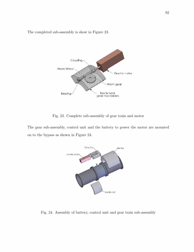
92
The completed sub-assembly is show in Figure 23.
Fig. 23. Complete sub-assembly of gear train and motor
The gear sub-assembly, control unit and the battery to power the motor are mounted
on to the bypass as shown in Figure 24.
Fig. 24. Assembly of battery, control unit and gear train sub-assembly

93
Figure 25 shows the overall bypass assembly with all the components mounted onto the
inner flange of pig body 1.
Fig. 25. Entire bypass assembly
The other end of the pig housing, pig body 2, is then mounted onto this assembly along
with a rubber gasket. Two pressure sensors are also mounted on the ends of the pigs to
measure the differentially pressure across the pig. The pig body 1 and pig body 2 are
then bolted to each other as shown in Figure 26.
Fig. 26. Mounting of pig body 2 onto basic assembly

94
The components enclosed within are sized such that the pig body 2 exerts a pressure on
the entire inner assembly and keeps it in place. This is shown in Figure 27.
Fig. 27. Complete pig housing
The entire assembly of the pig with varying degrees of transparency is shown in Figure
28 for a better understanding of the positioning and assembly of the pig.
Fig. 28. Pig assembly with transparent components

95
The components of the pigs and their placement in the pig housing is described in Figure
29.
Fig. 29. Various components of the pig
The scraper discs to carry out the actual cleaning operation are mounted on this com-
pletely enclosed pig housing as illustrated in Figure 30.
Fig. 30. Pig with scraper discs for cleaning

96
C. Conclusion
The assembly of the pig has been described in this chapter. It details the basic compo-
nents, and how they fit into the pig housing. This should provide a better insight into
understanding the functioning of the pig.

97
CHAPTER VII
PROOF OF CONCEPT AND PROPOSED TESTING
A. Introduction
The chapter discusses the proof of concept, an experimental setup which will demonstrate
the functional capabilities of controlling the pig velocity by maintaining the bypass flow.
This is a basic analogy, to verify that the concept used for designing the regulated by-
pass velocity pig actually works. The second stage would be an actual test using a
prototype pig in conditions similar to the ones that exist in the pipelines. It was not
possible to conduct any of these tests, because of the lack of funding. But once these
two tests are successful demonstrated, it would be possible to actually implement the
regulated-velocity pig for cleaning purposes in the oil pipelines.
B. Experimental Setup - Proof of Concept
The test setup is to demonstrate the capabilities and also the functionality of the pro-
posed pig in simulated conditions that resemble the actual operating conditions. The
setup focuses its attention only on the by-pass flow control system, which is fundamen-
tal in the pig maintaining regulated velocity and needs to be tested. The test doesn’t
concentrate on the pig scraping capabilities or the ability of pigs to traverse through
tight bends - as they have already been proven by the industry.
Thus, this setup aims at only proving that the assumption - the pig velocity can
be regulated by controlling the by-pass velocity through the pig. The lack of sufficient
funds prevented the actual building of a full scale prototype and testing it in commercial
pig testing setups.
The aim is to simulate these conditions without actually having to create a prototype
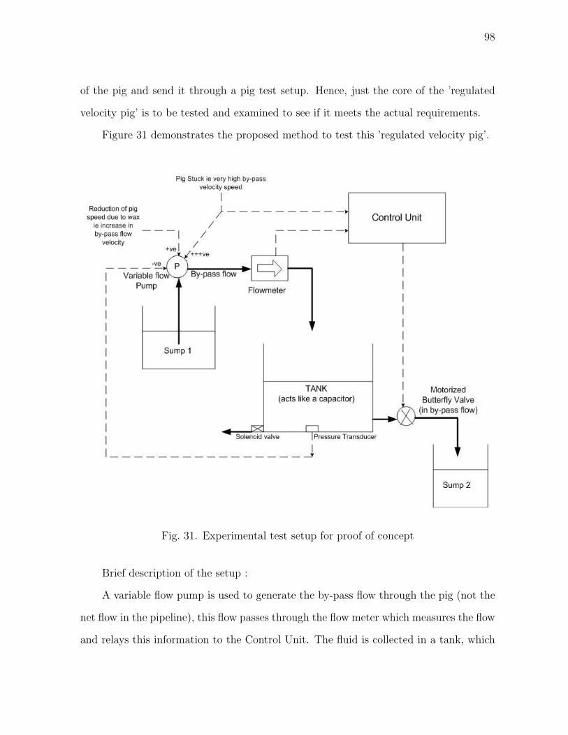
98
of the pig and send it through a pig test setup. Hence, just the core of the ’regulated
velocity pig’ is to be tested and examined to see if it meets the actual requirements.
Figure 31 demonstrates the proposed method to test this ’regulated velocity pig’.
Fig. 31. Experimental test setup for proof of concept
Brief description of the setup :
A variable flow pump is used to generate the by-pass flow through the pig (not the
net flow in the pipeline), this flow passes through the flow meter which measures the flow
and relays this information to the Control Unit. The fluid is collected in a tank, which

99
acts like a capacitor. At the bottom of the tank is a pressure transducer, and an outlet
to Sump 2 through a motor operated butterfly valve. This motor operated butterfly
valve is controlled by the control unit and is responsible for regulating the by-pass flow.
To simulate the actual conditions, two randomly generated inputs are necessary
- one which simulates the pig encountering wax deposition and slowing down i.e. the
by-pass velocity increases - which is simulated by increasing the pump flow. Secondly,
the case of the pig getting stuck is also a random input (which represents the function
of the accelerometer) - this relays information not only to the control unit but also to
the pump to increase the pump flow rate by a large margin (because when the pig is
stuck, all the flow goes through the by-pass and the by-pass velocity is very high)
A pressure transducer is provided in the tank to sense the pressure in the tank (which
effectively represents the pressure behind the pig), it is essential for the working of the
setup. If the pig is slowing down due to wax deposits, the butterfly valve is partially
closed and the pressure behind the pig starts increasing, and this increased pressure
helps the pig to dislodge and regain its velocity. The pressure transducer simulates the
pig dislodging and regaining velocity by sending signal to the pump to reduce flow i.e.
increase pig velocity, when a certain pressure is reached.
The pressure transducers also informs the control unit to open the bypass when the
pressure difference exceeds the safe limit in the actual pig.
Now, analyzing how the setup operates in the aforementioned four cases :
Case 1: Pig is moving in a clean section of the pipeline, and faces no resistance from
wax deposits or accumulations.
The pump is configured for a certain flow rate, which represents only the by-pass
flow and not the total flow. This is supposed to represent 30% of the total flow. The
flow meter relays this information to the control unit which regulates the butterfly valve,
such that flow out of butterfly valve is equal to the flow from the pump. Thus the fluid

100
level in the tank remains steady, and this symbolizes the constant pressure behind the
pig, which would help it maintain constant velocity.
Case 2 : Pig faces resistance from the wax deposits or wax accumulation.
As, it is difficult to predict when the pig might encounter resistance from wad,
to simulate the condition of the pig encountering wax resistance and slowing down, a
randomly generated input is necessary. This input sends signal to the pump to increase
the flow rate. This increase in flow rate i.e. by-pass flow rate represents the decrease in
pig speed. The flow rate increase is conveyed by the flow meter to the control unit. The
control unit then closes the valve accordingly to increase the pressure behind the pig.
The level of fluid in the tank rises, symbolizing increase in pressure behind the pig. Since
it is difficult to estimate at what pressures the pig would dislodge the wax, it is randomly
estimated. When this pressure is reached, the pressure transducer basically signals the
pump to reduce the flow rate and the by-pass flow rate decreases, signifying the increase
in velocity of the pig. The level of fluid in the tank starts falling and finally reaches a
steady value, suggesting the pressure propelling the pig reduces after the pig and soon
reaches a steady value. The pressure transducer basically simulates the operation of the
pig dislodging, breaking loose and regaining its velocity.
Note - this random generation of inputs does not exist in the actual ’regulated
velocity pig’, but is an integral part in the setup to simulate the conditions and the
behavior of the pig.
Case 3 : Pig gets completely stuck due to large wax accumulation
To simulate the pig getting stuck, another randomly generated input is required
which signals the pump to increase the flow by a large amount and also sends a signal
to the control unit. When the pig is stuck, the pig velocity is zero and hence the by-pass
velocity is very large, which is shown by the large flow rate of the pump.
Secondly, the signal sent to the control unit, represents the signal by the accelerom-

101
eter to the control unit, indicating that the pig is stuck. The control unit, upon getting
information from the flow meter and the accelerometer (in the set up it is just one source
- the random input) it completely shuts off the valve and allows pressure to build up
in the tank. Thus the level of fluid in the tank rises rapidly, indicating quick pressure
buildup of pressure behind the pig. As it is difficult to simulate how and when a pig
might get ’unstuck’, the pressure at which it might get unstuck is randomly generated.
This signal would be indicated by the accelerometer and not the flow meter as there
is no by-pass flow. And the control unit starts opening the valve when it gets a signal
from the accelerometer thus resuming the by-pass flow. This leads to the fluid level in
the tank falling till it reaches a steady level.
Case 4 : Pig is stuck and the pressure difference is too high
In this case, the solenoid valve which opens only when the pressure in the tank
i.e. the fluid level in the tank, reaches critical limit. The solenoid valve in the setup
is controlled based on the pressure readings by the pressure transducer. This simulates
the opening of the butterfly valve by the control unit based on the difference in pressure
across the pig as provided by the pressure transducers.
Note - the solenoid valve does not exist in the actual pig, it is an integral part of
the setup to symbolize the spring loaded safety valve.
This experimental setup test would help us identify some of the problems that might
arise in the actual scenario. It would also help us refine the control system being used for
the regulation of the by-pass flow. Once this experimental setup has been successfully
demonstrated, then a prototype of the pig may be built and tested before the actual
production and implementation of the regulated velocity pig can begin.

102
C. Actual Test Using Pig Prototype
After, the pig prototype has been built, it is still risky to implement it into the oil fields
right away. Some testing to check the standard of its performance is necessary. Smith, et
al, developed a test setup for RST Projects Ltd, to test their SAAM (Smart Acquisitions
Analysis Module)[21]. A similar test setup could be used to test the regulated velocity
pig. The test setup is described in detail in the following paragraphs.
An adequate sized pipe was considered, so as to accommodate the pig. The test
line consisted of two straight sections, which allowed the pig to reach the steady state
velocity of 70% of the flow velocity. The Figure 32 illustrates the proposed test section.
Fig. 32. Test setup for testing regulated velocity pig prototype
The entire test section was made from three, shorter pipe lengths which were ap-
proximately 0.8m in length. This was done in order to allow different internal conditions
to be simulated if required. These sections were internally coated with hard wax, soft
wax or were left clean.
Pure paraffin wax was used to produce the hard wax coating, while petroleum jelly
was used to simulate a soft internal coating. The amount of wax to produce a given
thickness over the inner surface of the pipe was calculated. This amount of wax was

103
heated in a crucible to above its melting point to get it into molten state. The pipe was
sealed from the other end using a stopper and the molten wax was poured inside. The
other end was also closed and the pipe was set on a rolling machine and rolled till the
wax had solidified. The coatings obtained were found to be of uniform thickness.
The different pipe lengths were then joined together to form the entire testing
section. Arrangements were made to monitor the velocity of the pig inside the pipe
by installing sensors in the test section. A variable flow pump was used, to enable the
simulation of actual conditions of varying flow rates.
The setup described above could be used to put the velocity regulated pig that
has been proposed through some rigorous tests. These test would determine the pig
performance under conditions almost similar to the actual conditions and would provide
an opportunity to improve and modify the pig.
D. Conclusion
Even though these tests have not been carried out because of the lack of financial support,
the aim of describing the tests is to discuss a way to actually test the proposed concept
in two different stages. These tests would act as a check at each stage, so that the
proposed concept is verified, strengthened and if needed modified before proceeding to
the next stage. The tests described above would provide a reality check for the proposed
design before the regulated velocity pig is put into use.

104
CHAPTER VIII
CONCLUSION
The objective of this research was to design a cleaning pig that would maintain a certain
velocity while cleaning. It was imperative to keep the design simple by using standard
commercially available components for the pig parts.
A secondary objective of the research was to provide certain basic features that
would enable elementary data collection. The aim of the data collection was to analyze
it in order to determine the actual condition in the pipeline.
This thesis, clearly identifies the problem and the need to maintain the pig at 70%
of the flow velocity. It also lists the basic requirements that are needed of the cleaning
pig in order to maintain constant speed. Various concepts are then developed to solve
the problem in different ways, they are then discussed and the best possible concept is
further developed.
The concept of using a motorized butterfly valve to control the bypass flow in order
to regulate the pig velocity was the best option and hence has been described in detail.
The step by step procedure for the design of such a pig is also detailed in this thesis.
The pig components are then modeled using Solidworks and the assembly procedure is
explained.
The thesis also describes two test setups that might be used to confirm and verify
the proposed design concept at different stages of development.
A. Conclusion
The initial objective of avoiding the use of any sensor, electrical equipment for regulat-
ing the velocity of the pig was found to be unpractical. The concepts developed with
this in mind, reveal that though some elementary control might be possible using just

105
mechanical means - it is not robust and reliable.
The final proposed concept of a regulated velocity pig using a motorized butterfly
valve is more robust, more reliable and has better control over the by-pass flow. It would
improve flow assurance and aid the petroleum industry in the following ways:
1. enhanced cleaning,
2. reduced pig runs,
3. better production,
4. lower chances of the pig getting stuck in the pipeline
5. reduced slugging effects.
These factors add up to lot of monetary savings for the oil industry in the long run.
In addition to the regulation of the pig velocity, the design also proposes to utilize
the onboard electronics like the accelerometer and the pressure transducers to gather
and store data onboard. It has been shown that even the elementary data gathered by
sensors like accelerometer and the pressure transducers may be used to correlate the
data to the conditions inside the pipe. This feature would transfer the ’dumb’ cleaning
pig into a ’semi-intelligent’ pig.
Thus, the combination of having regulated velocity and gathering of basic pipeline
data make the proposed concept a very attractive package for the oil industry.
B. Recommendations
This thesis involved the design of a regulated velocity cleaning pig, the concept needs to
be proved using the experimental test setup described in chapter 7. This would bring
out the faults and reliability issues especially in the control unit.
106
Though the details of the pig have been worked out in this thesis, the aforementioned
pig was not developed. There is need to take this research one step ahead and actually
build a prototype of the pig. The process of building the prototype would require further
work on this project using this thesis as a base. It might also reveal better and more
efficient ways of manufacturing the pig.
The developed prototype would then need to be tested in a specially built testing
rig as discussed in Chapter 7 in order to iron out the minor problems in the pig.

107
REFERENCES
[1] Baker Hughes, “Deepwater production - flow assurance,” [Online]. Available :
http://www.bakerhughes.com, Accessed October 2004.
[2] Baker Hughes, “Oil and gas production - paraffin and asphaltene controllers,”
[Online]. Available : http://www.bakerhughes.com, Accessed October 2004.
[3] Girard Industries, “Polly pig cleaning pigs by girard industries,” [Online]. Available
: http://www.girardind.com, Accessed September 2004.
[4] Pipetronix Incorporation, “Magnescanhr smart pig,” [Online]. Available:
http://www.new-technologies.org, Accessed September 2004.
[5] R. Anglisano A. Crouch and M. Jaarah, “Quantitative field evaluation of magnetic
flux leakage and ultrasonic in-line inspection,” Pipes and Pipeline Engineering, vol.
1, pp. 23–32, Jul-Aug 1996.
[6] H. Willems and O.A. Barbian, “Ultrasonic crack detection in pipelines by advanced
intelligent pigging,” Pipeline Technology, vol. 1, pp. 223–234, Jul-Aug 1995.
[7] Baker Hughes, “Baker hughes pipeline management group,” [Online]. Available :
http://www.bakerhughes.com, Accessed on August 2004.
[8] Association of Oil Pipe Lines, “Pipeline integrity final,” [Online]. Available :
http://www.aopl.org, Accessed on August 2004.
[9] Campbell Douglas, “Variable speed pigs for pipelines,” US Patent No 5,208,936,
May 11 1993.
[10] K. Campbell I. Smith, P.A. Couchman, “Pipeline pigs,” US Patent No 6,098,231,
September 6 1988.

108
[11] H. Goedecke G. Krieg, “Apparatus for electromagnetically testing the walls of
pipelines,” US Patent No 4,769,598, August 8 2000.
[12] Girard Industries, “Suggested pipe and pipeline pigging pressures and flows,” [On-
line]. Available : http://www.girardind.com, Accessed on October 2004.
[13] J.W.Hutchinson, ISA Handbook of Control Valves, Pittsburgh, Pennsylvania,
Instrument Society of America, 1971.
[14] T. Christopher Dickenson, Valves, Piping and Pipelines Handbook, vol. 1, Oxford,
U.K., Elsevier Advanced Technology, 3rd edition, 1999.
[15] Engineering Toolbox, “Butterfly valves, typical flow coefficients,” [Online]. Avail-
able : http://www.engineeringtoolbox.com, Accessed on September 2004.
[16] William J. Rahmeyer, “Application of butterfly valves for free discharge,
minimum pressure drop, and for choking cavitation,” [Online]. Available :
http://www.engineering.usu.edu, Accessed on September 2004.
[17] Honeywell/Tyco valves and control, “Resilient seat and high performance 2 and
3-way butterfly valves,” [Online]. Available : http://hbctechlit.honeywell.com, Ac-
cessed on August 2004.
[18] Globe Motors, “Brushless dc gearmotors,” [Online]. Available : http://www.globe-
motors.com, Accessed on August 2004.
[19] Panasonic, “Meeting the needs of portable electronic devices : Lithium ion battery,”
[Online]. Available : http://www.panasonic.com, Accessed on September 2004.
[20] G. Smith B. Snodgrass, “Low-cost pipeline inspection by the measurement and
analysis of pig dynamics,” Pipes and Pipelines International, pp. 35–43, 2001.

109
[21] D. Russell E.H. Owens G.H. Smith, G. Short, “Testing of low cost instruments for
the identification of wax in a hydrocarbon pipeline,” in International Society of
Offshore and Polar Engineers, 2000.
[22] K. Balaveera Reddy K. Mahadevan, Design Data Handbook, New Delhi, India,
CBS Publishers and Distributors, third edition, 2000.
[23] Richard G. Budynas Warren C. Young, Roark’s Formulas for Stress and Strain,
New York, McGraw Hill Publishers, seventh edition, 2002.

110
APPENDIX A
SOLID MODELS OF PIG COMPONENTS
This shows the detailed drawings of the pig parts along with their dimensions.
Fig. 33. Pig housing - pig body 1

111
Fig. 34. Pig housing - pig body 2
Fig. 35. Pig housing - pig body 3

112
Fig. 36. Turbine flowmeter

113
Fig. 37. 4” Butterfly valve

114
Fig. 38. DC gear motor
Fig. 39. Electric battery pack

115
Fig. 40. Worm wheel
Fig. 41. Worm gear

116
Fig. 42. Gear box to house worm wheel and worm gear
Fig. 43. Coupling to couple motor shaft and worm wheel

117
Fig. 44. Pressure transducer
Fig. 45. Gasket for pig body 3

118
Fig. 46. Gasket for pig body 1,2
Fig. 47. Scraper discs

119
VITA
Chaitanya Yardi was born in Vadodara, Gujarat, India on the 12th of November,
1979. He received his B.E. degree in mechanical engineering from Gujarat University,
India, in 2001. In August 2002 he joined the master’s degree program in Mechanical
Engineering at Texas A&M University. Permanent Address: Chaitanya Yardi, 7 Krish-
nadham Society, Manjalpur, India - 390011 Phone - 91-265-2644648. E-mail address :
chaitanya [email protected]
The typist for this thesis was Chaitanya Yardi.