design of reliable and low cost substrate heater for thin film
TRANSCRIPT

Abstract—The substrate heater designed for this investigation is a front side substrate heating system. It consists of 10 conventional tungsten halogen lamps and an aluminum reflector, total input electrical power of 5 kW. The substrate is heated by means of a radiation from conventional tungsten halogen lamps directed to the substrate through a glass window. This design allows easy replacement of the lamps and maintenance of the system. Within 2 to 6 minutes the substrate temperature reaches 500 to 830 C by varying the vertical distance between the glass window and the substrate holder. Moreover, the substrate temperature can be easily controlled by controlling the input power to the system. This design gives excellent opportunity to deposit many deferent films at deferent temperatures in the same deposition time. This substrate heater was successfully used for Chemical Vapor Deposition (CVD) of many thin films, such as Silicon, iron, etc.
Keywords—CVD, Halogen Lamp, Substrate Heater, Thin Films.
I. INTRODUCTION
UARTZ halogen lamps efficiently convert electrical energy into radiated heat (light), at low 15 to 25 lumens
per watt. Easy to adjust and replace the lamps and to control the input power allows flexibility for temperature variability as needed for the process. In Thermal Chemical Vapor Deposition (TCVD) systems, heating the substrate can be accomplished by any one of three heat transfer methods, conduction, convection and radiation. Heating a substrate by convection or conduction heat transfer requires a physical contact between the heating source and the substrate, while radiative heat transfer occurs when a temperature difference exists between the substrate and the heating source without any physical contact.
One of the most important applications of using halogen lamps in thin films processes is a heating substrate source in rapid thermal processes such as oxidation, annealing, and chemical vapor deposition. Heating by halogen lamps provide a convenient, efficient and clean environment thermal source. Energy saving can be achieved by taking advantage of the capability to focus the light on a small area that needs to be heated. A halogen lamp is a diffuse emitter, but by combining the lamps with a reflector, the radiation could be directed and focused on specific areas. Halogen lamps and aluminum reflector system are successfully used and offer unique benefits in many industrial heating requirements. The reflector collects the lamp radiation and produces a high intensity spot in front of it.
Ali Eltayeb Muhsin is with the Mechanical and Industrial Engineering
Department, Faculty of Engineering, Tripoli University, Tripoli, Libya (phone: 00218 92 6054013, e-mail: [email protected]).
Mohamed Elhadi Elsari is with School of Mechanical engineering, Academy of higher education, Tripoli, Libya. (Tel.00218 91 3589151, e-mail: [email protected])
.
This method also needs absorbing substrates so that a substrate high absorptive can absorb a high percentage of the radiation emitted by the lamps. By using more than one halogen lamp in the system, a higher heat flux and thus a higher substrate temperature can be obtained. The substrate temperature might be varied from ambient to temperatures above 1000 K, by designing a good heater system, by controlling the lamp input electrical power and by limiting the distance between the heating system and the substrate.
The high heat flux capability of halogen lamp heater systems allows heating the substrate much faster than in many other heating processes. Depending on the applications, either, both front and back sides of the substrate are heated or only one side. Different reflector geometries may be applied such as a horizontal or a parabolic geometry.
Numerous numerical simulation and experimental studies have been presented in literature reviews concentrating on studying of: lamp heating system design, as in [2], [5], [10], [12], [15]. Substrate temperature uniformity and control, as in [3], [6], [8], [11], [16]. CVD of thin films, as in [7], [13], [14].
Depositing of a film is very dependent on substrate temperature in order to induce an appropriate chemical reaction occurring on the surface of the substrate. Some films require low deposition temperature while others require high deposition temperature, depending on the phase diagram. Also the crystalline of a film depends on temperature; while an amorphous phase is generally deposited at low temperature a crystalline phase needs higher temperature. The substrate heater system was designed that utilizes tungsten halogen lamps as a radiant heat source to heat up the substrate. The system consists of four main parts: chamber, halogen lamp heater, light entrance window, and substrate holder. The descriptions of each part and a proof of the achievable using this design are presented in the next sections. Fig. 1 shows a schematic diagram of the designed system components.
II. SYSTEM COMPONENTS
The chamber is a vertical cylinder made from a stainless steel (AISI 304, DN 250) with height of 200 mm. Both top and bottom flanges are standard CF flanges sealed with copper gaskets, (DN 250 CF). Several KF standard flanges, (KF50, KF40, and KF25) are placed at different positions at the wall, at the top and at the bottom flanges for gas tube feedings, exhaust gases, vacuum connections, nozzle holder, thermal connections and temperature measurements. All KF standard flanges are sealed with viton O-ring gasket such that the users can carry out maintenance operations and substrate replacements easily. Two nozzles are installed inside the CVD chamber, a deposition nozzle and a window protection nozzle. The window protection nozzle is designed as a linear tube shower nozzle and installed horizontally under one side of the window.
Ali Eltayeb Muhsin, Mohamed Elhadi Elsari
Design of Reliable and Low Cost Substrate Heater for Thin Film Deposition
Q
A. Chamber
World Academy of Science, Engineering and TechnologyInternational Journal of Mechanical and Mechatronics Engineering
Vol:6, No:8, 2012
1503International Scholarly and Scientific Research & Innovation 6(8) 2012 ISNI:0000000091950263
Ope
n Sc
ienc
e In
dex,
Mec
hani
cal a
nd M
echa
tron
ics
Eng
inee
ring
Vol
:6, N
o:8,
201
2 w
aset
.org
/Pub
licat
ion/
1016
4

glass window
A flow of inert gas (argon) is introduced through this nozzle in order to protect the window from deposition of species during the deposition process. The glass has to be clean so that the required light from the lamps for specific substrate temperature can be transmitted through the glass continuously during the deposition period. This is important also at the same time, while the glass absorbs some light and getting hotter, the deposition might be occurred on the glass surface as well. So, the argon flow will transfer all the products after the precursor decomposed away from the surface of the glass window.
The substrate heater designed for this investigation is designed to heat up the top side of the substrate by means of a radiation from conventional tungsten halogen lamps. The heating system consists of 10 tungsten halogen lamps, with a total electrical power input of 5 kW, and an aluminum reflector. The single halogen lamps are type of double ended linear sources (R7S), 118 mm in length, 500 Watt rated power, ultraviolet free, 9500 Lumen, 230 Volt and radiation output of ~20%. A polished parabolic aluminum reflector is used to reflect and direct the amount of light flux incident on the substrate. The reflector and lamp housing are continuously cooled by the water cooling system. The heating system was build so that it can be easily moved away from the surface of the window. This design allows easy replacement of the lamps and maintenance of the system. The lamps were arranged under the parabolic aluminum reflector as shown in Fig. 1 (a). The bulb and the socket of the lamp are cooled by a nitrogen flow. The environmental temperature within the lamp is kept as low as 350 C for lamp damage protection. The lamp input electrical power can be manually switching on and off each lamp or each lamp zone. It may also be controlled continuously depending on the result of a measurement of the substrate temperature. A thermocouple, type K is attached to the back side of the substrate to measure and monitor the substrate temperature.
Since the halogen lamp heating system used to heat the substrate was placed outside the CVD system chamber, a specific design of the top flange is required. A borosilicate glass window is constructed on the top flange to transmit the radiation from the heating system. This glass is relatively cheap compared to quartz glass. 90% of visible light and infrared radiation spectrum up to 2 micrometer is transmitted from 2 to 5 mm thickness (Hecker Glastechnik, ID-Nr 936803). The area of the window was designed as 76 by 76 mm, and build from two glass plates, each 3.3 mm thick, separated by 5 mm air gap as shown in the schematic diagram Fig. 1 (b). The bottom glass plate, 86 x 86 mm, is glued into the flange surface with high temperature glue.
This glue is chosen to allow the thermal expansion of the glass during the heating process and to its resistance to high temperature (high temperature glue, LOCTITE 5399 US, -8 to 275 C, peak of 350 C).
Fig. 1 A schematic diagram of HLR components: (a) halogen lamp
heater, (b) glass window
(a)
Halogen lamp
Aluminum reflector
Water entrance for cooling the reflector
(b)
Chilled air entrance for cooling the window
Top flange
B. Halogen Lamp Heater
C. Light Entrance Window
World Academy of Science, Engineering and TechnologyInternational Journal of Mechanical and Mechatronics Engineering
Vol:6, No:8, 2012
1504International Scholarly and Scientific Research & Innovation 6(8) 2012 ISNI:0000000091950263
Ope
n Sc
ienc
e In
dex,
Mec
hani
cal a
nd M
echa
tron
ics
Eng
inee
ring
Vol
:6, N
o:8,
201
2 w
aset
.org
/Pub
licat
ion/
1016
4

Fig. 2 A schematic diagram of CVD chamber and the substrate holder.
The top glass plate, 96 x 96 mm, is placed free above the
bottom glass plate level. A 5 mm air gap is allowed between the two glass plates for window cooling purposes. A forced chilled air flow is provided to protect the glass and the glue from overheating. The exhaust air temperature is monitored by a thermocouple placed inside the air gap and kept always below 175 C.
The substrate holder designed to achieve high temperatures consists of a stainless steel cylinder with inner diameter of 82 mm and height of 30 mm, as shown in Fig. 2. The cylinder is filled with an isolation material (silica wool 125), having a density of 128 kg/m3 and a thermal conductivity of 0.21 W/m K at 800 C and covered with 2 mm thick stainless steel cover. This cylinder is fixed on a stainless steel arm, which may be elevated to control the distance between the halogen lamp heater and the substrate, later referred to as heater/substrate distance. The holder is positioned in the center of the chamber directly below the window. The substrate temperature was measured by a thermocouple connected to the backside of the substrate as shown in Fig. 2. A uniform temperature distribution might be assumed across the substrate at any time during a transient process, while the Biot number, which relates the conduction heat transfer resistance of the substrate (Rcond) to the convection heat transfer resistance (Rconv), (Bi = Rcond / Rconv) is much smaller than unity, (Bi << 1).
III. SUBSTRATE TEMPERATURE OPTIMIZATION
A. Theoretical Results
Before selecting the final geometry of the reactor, the radiative power from halogen lamps required to heat the substrate was investigated.
The radiation spectrum of a halogen lamp (Eλ) at filament lamp temperature of 3000 K was calculated from Planck distribution equation and plotted in Fig. 3.
This temperature is given by the supplier (Qsram, www.osram.com). There are several parameters, which had to be considered during the evaluation of the substrate temperature. These parameters are area and material of the substrate, design of the substrate holder, distance between the lamp and the substrate (heater/substrate distance), geometry of the reflector, selections of the halogen lamps, the glass of the window and the ambient conditions.
The portion of radiation emitted from the halogen lamp and absorbed by the substrate might be computed from:
LS QQ••
= α )1(
LL GFQ ϕ=•
)2(
L
L
GW
•
=ϕ )3(
−
=π2
2tan2 1 dw
ll
FS
L
S )4(
Where the subscripts L and S related to the lamp and substrate respectively, and α is the substrate absorptivity, GL is the input electrical lamp power, WL is the equivalent light power (9500 Lumen for every single of the used lamps), φ is the lamp efficiency and F is the geometry factor depending on substrate size (length lS and width wS), heater/substrate distance d, the lamp length lL. Fig. 4 shows a schematic diagram of shining substrate with one halogen lamp.
0.0E+00
1.0E+06
2.0E+06
3.0E+06
4.0E+06
0 1 2 3 4 5 6
Eλ (
W/m
².µ
m)
Wavelength, λ(µm)
Fig. 3 Halogen lamp radiation spectrum at filament temperature of 3000 K
(5)
Where, ε is the emissivity of the substrate, A is the substrate area, σ is the Stefan-Boltzmann constant (5.67x10⁻⁸ W/m2.K4) and T is the absolute substrate temperature. As the radiant power of the substrate is primarily a function of the surface temperature, small temperature increases result in large power increases.
Performing an energy balance on the substrate where, the amount of radiation absorbed by the substrate surface is equal to the radiation emitted by the substrate surface.
N2 flow entrance for cooling the
lamps
thermocouple
substrate holder
deposition nozzle
substrat
exhaust
CVD chamber
window protection
nozzle
α
4TAQ σε=•
D. Substrate Holder
World Academy of Science, Engineering and TechnologyInternational Journal of Mechanical and Mechatronics Engineering
Vol:6, No:8, 2012
1505International Scholarly and Scientific Research & Innovation 6(8) 2012 ISNI:0000000091950263
Ope
n Sc
ienc
e In
dex,
Mec
hani
cal a
nd M
echa
tron
ics
Eng
inee
ring
Vol
:6, N
o:8,
201
2 w
aset
.org
/Pub
licat
ion/
1016
4

outin QQ••
= )6(
Fig. 4 A schematic diagram of shining substrate with one halogen lamp where (l l) is a lamp length, (
d
d) is a distance between the lamp and the substrate; (ls and ws) are the length and the width of the
substrate, (2α) is a plane angle
Fig. 5 Calculated amount of halogen lamp radiation emitted to the substrate based on substrate area (30 x 20) mm2 and lamp/substrate
distance for: (a) 500W and (b) 5000W as a single lamp source.
The total heat transfer from the surface of the substrate was calculated from (7) based on the design of the substrate holder, the radiative heat transfer from the front side and the conductive heat transfer from the back side of the substrate.
)7(
Where k and L are a thermal conductivity and a thickness of the isolating material respectively, ∆T is the temperature difference between the top and the bottom of the substrate holder.
To evaluate this model some assumption were made: one dimensional steady state condition, negligible convection heat transfer, substrate emissivity and absorptivity are equal, (0.6). Therefore, the required power for heating the substrate to a specific temperature could be estimated from this simple calculation. Fig. 6 shows the relation between the required heat transfer rate by a radiation and the substrate temperature. The absorbed heat by the substrate should be improved by using the aluminum reflector. The comparison between the theoretical substrate temperature and experimentally measured temperature as a function of heater/substrate distance is shown in Fig. 7. The real measured temperatures at heater/substrate distance of 50 and 60 mm are slightly below the calculated temperatures curve. It seems that the effectiveness of the used reflector in this set-up is quite low; it is approximately 10%, perhaps due to thermal degradation of the surface of the reflector.
0
20
40
60
0 200 400 600 800 1000 1200
Temperature (°C)
Hea
t flu
x (W
)
Fig. 6 The required absorbed heat flux by the substrate as a function
of substrate temperature: calculated using (3).
400
600
800
1000
1200
0 20 40 60 80 100 120
Heater/substrate distance (mm)
Calculated temperature
Measured temperature
Sub
stra
tetem
pera
ture
(°C
)
Fig. 7 Measured and calculated substrate temperature as a function of
heater/substrate distance.
B. Validation of the Substrate Heater Design:
After choosing the geometry of the HLR and constructing the reactor, the heating rate and the achievable maximum temperature of substrate were tested.
The substrates used for this investigation were pieces of silicon wafers, Si(100), having a thickness of 0.5 mm. The substrates, (20 x 30 mm) were introduced into the chamber manually and placed horizontally on the substrate holder, Fig. 2.
Sw
Ll
Sl
d
2α d
+= ƥ
LTAkTAQ
out4σε
World Academy of Science, Engineering and TechnologyInternational Journal of Mechanical and Mechatronics Engineering
Vol:6, No:8, 2012
1506International Scholarly and Scientific Research & Innovation 6(8) 2012 ISNI:0000000091950263
Ope
n Sc
ienc
e In
dex,
Mec
hani
cal a
nd M
echa
tron
ics
Eng
inee
ring
Vol
:6, N
o:8,
201
2 w
aset
.org
/Pub
licat
ion/
1016
4

Water, chilled air and nitrogen flows were provided from the conventional flow system in the laboratory in order to cool and protect the aluminum reflector, the window and the halogen lamps respectively. The valves of the cooling systems were opened before the halogen lamp heater is switched on. The substrate temperature was measured and monitored by the thermocouple attached to the backside of the substrate.
0
200
400
600
800
1000
0 120 240 360 480 600 720 840 960
Time (sec)
(a)
Tem
pera
ture
( °
C)
(b)
Fig. 8 Average heating rate of the substrate at 1 atm and substrate
temperature set point of 800°C, for heater/substrate distance of (a) 50 mm and (b) 60 mm
0
200
400
600
800
1000
0 120 240 360 480 600 720 840 960
Time (sec)
(a)
(b)
Tem
pera
ture
( °
C)
Fig. 9 Average heating rate of the substrate at 30 mbar and substrate temperature set point of 800 C for heater/substrate distance of (a) 50
mm and (b) 60 mm To optimize the reactor for the designed maximum substrate
temperature of 800 C, the reactor was tested at atmospheric and low pressure (30 mbar), and the substrate holder was adjusted at two heater/substrate distances: 60 and 50 mm. The experimental runs were performed by applying the maximum electrical power (5 kW) to the lamps and waiting long enough for the substrate to reach the stationary state. The maximum temperature reaches 750 C at 60 mm and 830 C at 50 mm after approximately 360 seconds. After that, the lamp power was controlled according to the thermocouple feed back to the set point temperature of 800 C and the substrate temperatures were acquired every 30 seconds.
The average substrate heating rate profiles are illustrated in Fig. 8 at 1 atm and Fig. 9 at 30 mbar reactor pressures. Curves (a) and (b) show the substrate heating rates profiles at 50 mm and 60 mm heater/substrate distance, respectively. The values of the transient substrate temperatures illustrated by curves (a) and (b) were fitted to an exponential function, (T0+(Tmax-T0)(1-e(-kt))).
The time constant k is: (k = 0.01 at 60 mm , k = 0.012 at 50 mm), t is the heating time, T0 is the room temperature and Tmax is the maximum substrate temperature related to each case, (800 C at 50 mm, 770 C at 60 mm). The set point temperature, which is 800 C, cannot be reached at 60 mm heater/substrate distance as the maximum radiation absorbed by the substrate is not enough to increase the substrate temperature to the set point temperature. The maximum temperatures, achieved in this case are 737 C at 1 atm and 772 C at 30 mbar after 840 seconds heating time. But, it is successfully reached and well controlled at 50 mm heater/substrate distance after 360 seconds, where the absorbed radiation by the substrate is enough in this case to increase the temperature to the designed control set point.
0
200
400
600
800
1000
0 5 10 15 20 25 30 35
Time (min)
Tem
pera
ture
( °
C)
Fig. 10 Average substrate temperature profile during the substrate
cooling process, (Halogen lamp heater was switched off).
0
50
100
150
200
0 2 4 6 8 10 12 14 16 18 20
Time (min)
Tem
per
atu
re (
°C
)
Fig. 11 Window temperature profile during heating process at
substrate temperature set point of 800 C
These results are presented by curves (a) and (b) in Fig. 8 and 9. The slightly change in the value of temperature appears in curve (a) after 360 seconds is due to the controller hysteresis. Different set point temperatures below 800 C were also tested (not shown here) and successfully applied for the deposition of thin films.
After the heater was switched off, the cooling rate of the substrate was measured; this temperature profile is shown in Fig. 10. The cooling rate was a function of (T0+ (Tmax-T0) e
(-kt)) having constant time of (k = 0.17) until reaching of 350 C, after that the cooling rate was delayed because of the presence of the isolation material.
World Academy of Science, Engineering and TechnologyInternational Journal of Mechanical and Mechatronics Engineering
Vol:6, No:8, 2012
1507International Scholarly and Scientific Research & Innovation 6(8) 2012 ISNI:0000000091950263
Ope
n Sc
ienc
e In
dex,
Mec
hani
cal a
nd M
echa
tron
ics
Eng
inee
ring
Vol
:6, N
o:8,
201
2 w
aset
.org
/Pub
licat
ion/
1016
4
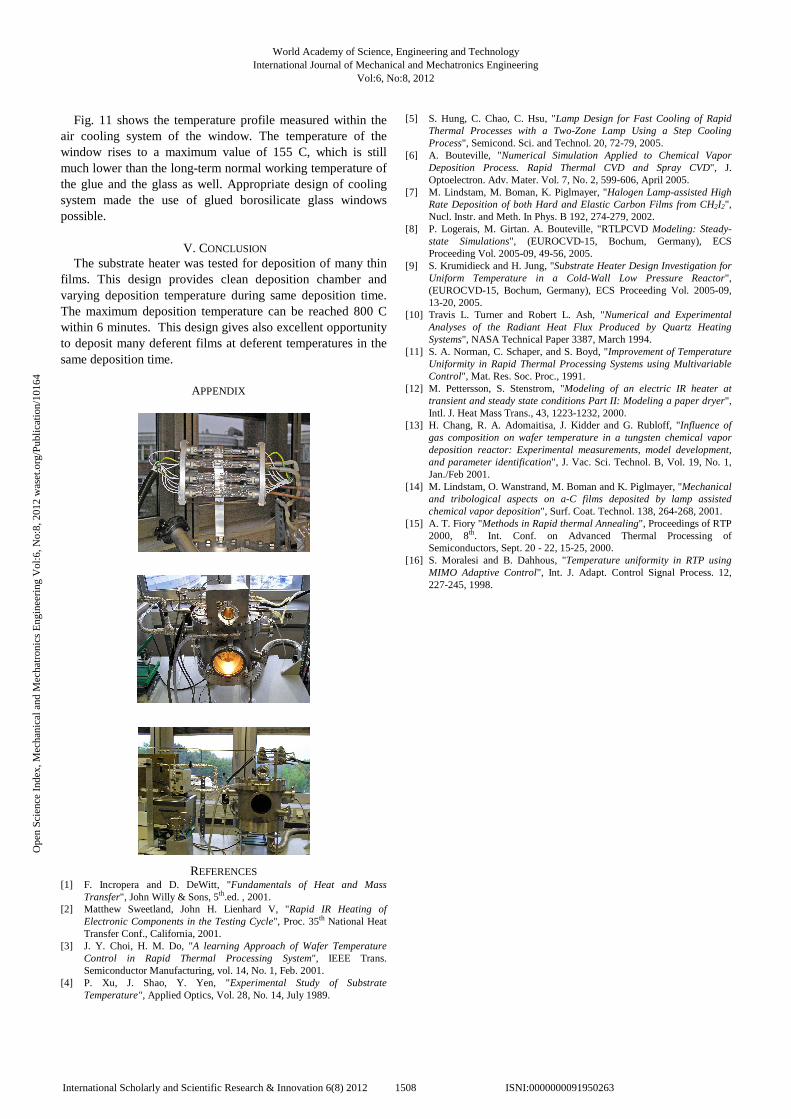
Fig. 11 shows the temperature profile measured within the air cooling system of the window. The temperature of the window rises to a maximum value of 155 C, which is still much lower than the long-term normal working temperature of the glue and the glass as well. Appropriate design of cooling system made the use of glued borosilicate glass windows possible.
V. CONCLUSION
The substrate heater was tested for deposition of many thin films. This design provides clean deposition chamber and varying deposition temperature during same deposition time. The maximum deposition temperature can be reached 800 C within 6 minutes. This design gives also excellent opportunity to deposit many deferent films at deferent temperatures in the same deposition time.
REFERENCES [1] F. Incropera and D. DeWitt, "Fundamentals of Heat and Mass
Transfer", John Willy & Sons, 5th.ed. , 2001. [2] Matthew Sweetland, John H. Lienhard V, "Rapid IR Heating of
Electronic Components in the Testing Cycle", Proc. 35th National Heat Transfer Conf., California, 2001.
[3] J. Y. Choi, H. M. Do, "A learning Approach of Wafer Temperature Control in Rapid Thermal Processing System", IEEE Trans. Semiconductor Manufacturing, vol. 14, No. 1, Feb. 2001.
[4] P. Xu, J. Shao, Y. Yen, "Experimental Study of Substrate Temperature", Applied Optics, Vol. 28, No. 14, July 1989.
[5] S. Hung, C. Chao, C. Hsu, "Lamp Design for Fast Cooling of Rapid Thermal Processes with a Two-Zone Lamp Using a Step Cooling Process", Semicond. Sci. and Technol. 20, 72-79, 2005.
[6] A. Bouteville, "Numerical Simulation Applied to Chemical Vapor Deposition Process. Rapid Thermal CVD and Spray CVD", J. Optoelectron. Adv. Mater. Vol. 7, No. 2, 599-606, April 2005.
[7] M. Lindstam, M. Boman, K. Piglmayer, "Halogen Lamp-assisted High Rate Deposition of both Hard and Elastic Carbon Films from CH2I2", Nucl. Instr. and Meth. In Phys. B 192, 274-279, 2002.
[8] P. Logerais, M. Girtan. A. Bouteville, "RTLPCVD Modeling: Steady-state Simulations", (EUROCVD-15, Bochum, Germany), ECS Proceeding Vol. 2005-09, 49-56, 2005.
[9] S. Krumidieck and H. Jung, "Substrate Heater Design Investigation for Uniform Temperature in a Cold-Wall Low Pressure Reactor", (EUROCVD-15, Bochum, Germany), ECS Proceeding Vol. 2005-09, 13-20, 2005.
[10] Travis L. Turner and Robert L. Ash, "Numerical and Experimental Analyses of the Radiant Heat Flux Produced by Quartz Heating Systems", NASA Technical Paper 3387, March 1994.
[11] S. A. Norman, C. Schaper, and S. Boyd, "Improvement of Temperature Uniformity in Rapid Thermal Processing Systems using Multivariable Control", Mat. Res. Soc. Proc., 1991.
[12] M. Pettersson, S. Stenstrom, "Modeling of an electric IR heater at transient and steady state conditions Part II: Modeling a paper dryer", Intl. J. Heat Mass Trans., 43, 1223-1232, 2000.
[13] H. Chang, R. A. Adomaitisa, J. Kidder and G. Rubloff, "Influence of gas composition on wafer temperature in a tungsten chemical vapor deposition reactor: Experimental measurements, model development, and parameter identification", J. Vac. Sci. Technol. B, Vol. 19, No. 1, Jan./Feb 2001.
[14] M. Lindstam, O. Wanstrand, M. Boman and K. Piglmayer, "Mechanical and tribological aspects on a-C films deposited by lamp assisted chemical vapor deposition", Surf. Coat. Technol. 138, 264-268, 2001.
[15] A. T. Fiory "Methods in Rapid thermal Annealing", Proceedings of RTP 2000, 8th. Int. Conf. on Advanced Thermal Processing of Semiconductors, Sept. 20 - 22, 15-25, 2000.
[16] S. Moralesi and B. Dahhous, "Temperature uniformity in RTP using MIMO Adaptive Control", Int. J. Adapt. Control Signal Process. 12, 227-245, 1998.
APPENDIX
World Academy of Science, Engineering and TechnologyInternational Journal of Mechanical and Mechatronics Engineering
Vol:6, No:8, 2012
1508International Scholarly and Scientific Research & Innovation 6(8) 2012 ISNI:0000000091950263
Ope
n Sc
ienc
e In
dex,
Mec
hani
cal a
nd M
echa
tron
ics
Eng
inee
ring
Vol
:6, N
o:8,
201
2 w
aset
.org
/Pub
licat
ion/
1016
4