design of small four-rotor uav transmission line
TRANSCRIPT

Design of small four-rotor UAV transmission line inspection systems
Jinhu Liao1, Qingyong Zhang1, Yixin Su1, Guoting Qian2 1School of Automation, Wuhan University of Technology Wuhan, 430070 China
2School of English, Wuhan University of Technology Wuhan, 430070 China
Keywords: quad-rotor Unmanned Helicopter; STM32F407ZGT6; transmission line inspection; Wireless transmission
Abstract. A small four-rotor UAV transmission line inspection system is designed, which not only can cruise and avoid obstacles automatically, but also can be controlled with the remote. The system carries out data collection of transmission lines by the camera module, makes use of FPV technology to realize the image transmission in real time, with high-performance controller STM32F40ZGT6 as the control core, using a small four-rotor UAV to achieve autonomous cruise. The test results show that the transmission line inspection system can accomplish the task of the patrol line perfectly, and the function of the autonomous patrol line can reduces the labor cost greatly.
Introduction
In recent years, with the continuous improvement of the level of transmission voltage, transmission line inspection is becoming more and more important for the maintenance of regional power grid’s security, stability, and efficient operation [1-3]. The traditional artificial line inspection method has not only heavy workload and complex conditions, especially for the transmission line inspection on the mountain and across rivers, or in the flood, ice disaster, landslide, patrol inspection line during the night, but also is time-consuming, with high cost of human resources, difficulties, risks [9-11]. However, in this paper, a new intelligent transmission line inspection system is designed, and the ultrasonic ranging modules are used to avoid obstacles, while the high definition digital camera is used for the image acquisition part. The controller adopts STMicroeletronics NV’s STM32F407ZGT6 single-chip microcomputer as the core controller and analyzes the information collected. At the same time, the acquisition of the image can be transmitted through FPV technology to display on the ground platform, which is convenient and safe for the technical personnel to detect and reduce the labor cost [4-8].
System Design
The overall framework of the transmission line inspection system for the rotor UAV is shown in Fig. 1. The system is composed of two parts, which are the rotor UAV platform and the ground control display platform. In rotor UAV platform, adopting STMicroelectronics’s 32-bit STM32F407ZGT6 single-chip microcomputer, which is a high performance controller with ARM CortexTM-M4 core, the controller receives the navigation information of guided system on the platform, obstacle information of obstacle avoidance system, remote control information of remote control receiver, video information of image transmission system and posture information of the UAV, then analyses these data and adopts corresponding treatment. And in the ground control display platform, mainly composed of the UAV remote control and image acquisition display system, the UAV remote control can help technical personnel to carry out the line inspection task manually, and the image acquisition display system mainly works for image receiving, displaying and storing task.
2nd International Conference on Machinery, Materials Engineering, Chemical Engineering and Biotechnology (MMECEB 2015)
© 2016. The authors - Published by Atlantis Press 655

Fig. 1 System diagram
Main Module Design
A. Rotor UAV flight control system The flight control system of the UAV includes attitude acquisition, attitude control and dynamic
system, and the rotor UAV control system is shown in Fig. 2, using the MPU6050 six axis digital sensor and HMC5883L magnetometer to obtain the initial data, the controller uses a complementary filter to fuse the data of the three axis accelerometer, the three axis gyroscope and magnetometer to get the accurate rotor UAV attitude. Through the cascade PID, controller outputs a PWM to the brushless motor speed controller, and then control the brushless motor, so that the balance of the UAV can be maintained effectively.
For power system, we selected non-brush motor with excellent performance, Owing to the cancellation of the mechanical contact structure composed of brush and commutator, the brushless motor has no commutation spark and mechanical friction, so the system has high efficiency, no electromagnetic interference, long service life and reliable operation. And with the brushless motor speed-control device working together, we can ensure the good performance of the power system.
Fig. 2 Rotor UAV control system
B. Image transmission system The most important information the Rotor UAV line inspection acquired is the image
information. The quality of the image transmission has a direct impact on the technical personnel to determine the line fault, so a good image transmission system is very important. In this system, FPV technology is adopted to realize real-time image transmission. FPV technology, the first person view perspective technology, is mainly composed of camera, image transmitter, image receiving end and display screen.
The information collected by the camera is transmitted through the image transmitting port of the rotor UAV platform. On the ground control display platform, images are received and displayed on the display screen by the image receiver. It can also be stored in the memory card easily for second inspection.
656
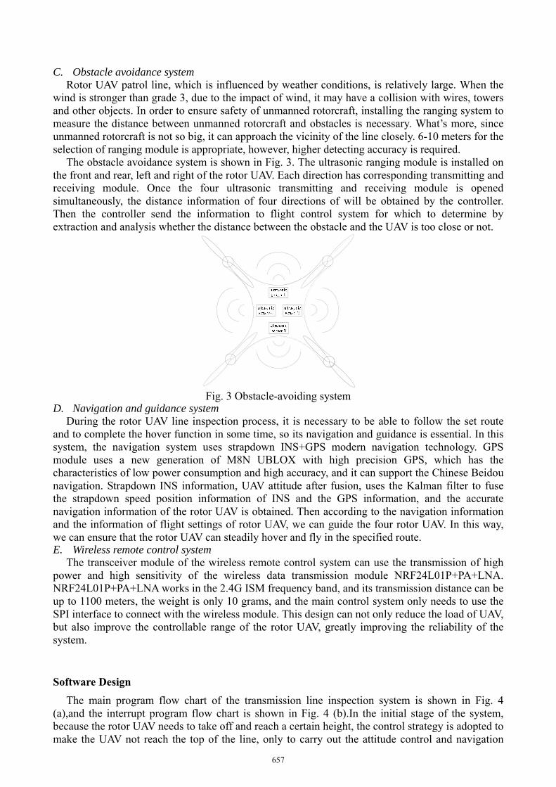
C. Obstacle avoidance system Rotor UAV patrol line, which is influenced by weather conditions, is relatively large. When the
wind is stronger than grade 3, due to the impact of wind, it may have a collision with wires, towers and other objects. In order to ensure safety of unmanned rotorcraft, installing the ranging system to measure the distance between unmanned rotorcraft and obstacles is necessary. What’s more, since unmanned rotorcraft is not so big, it can approach the vicinity of the line closely. 6-10 meters for the selection of ranging module is appropriate, however, higher detecting accuracy is required.
The obstacle avoidance system is shown in Fig. 3. The ultrasonic ranging module is installed on the front and rear, left and right of the rotor UAV. Each direction has corresponding transmitting and receiving module. Once the four ultrasonic transmitting and receiving module is opened simultaneously, the distance information of four directions of will be obtained by the controller. Then the controller send the information to flight control system for which to determine by extraction and analysis whether the distance between the obstacle and the UAV is too close or not.
Fig. 3 Obstacle-avoiding system
D. Navigation and guidance system During the rotor UAV line inspection process, it is necessary to be able to follow the set route
and to complete the hover function in some time, so its navigation and guidance is essential. In this system, the navigation system uses strapdown INS+GPS modern navigation technology. GPS module uses a new generation of M8N UBLOX with high precision GPS, which has the characteristics of low power consumption and high accuracy, and it can support the Chinese Beidou navigation. Strapdown INS information, UAV attitude after fusion, uses the Kalman filter to fuse the strapdown speed position information of INS and the GPS information, and the accurate navigation information of the rotor UAV is obtained. Then according to the navigation information and the information of flight settings of rotor UAV, we can guide the four rotor UAV. In this way, we can ensure that the rotor UAV can steadily hover and fly in the specified route. E. Wireless remote control system
The transceiver module of the wireless remote control system can use the transmission of high power and high sensitivity of the wireless data transmission module NRF24L01P+PA+LNA. NRF24L01P+PA+LNA works in the 2.4G ISM frequency band, and its transmission distance can be up to 1100 meters, the weight is only 10 grams, and the main control system only needs to use the SPI interface to connect with the wireless module. This design can not only reduce the load of UAV, but also improve the controllable range of the rotor UAV, greatly improving the reliability of the system.
Software Design
The main program flow chart of the transmission line inspection system is shown in Fig. 4 (a),and the interrupt program flow chart is shown in Fig. 4 (b).In the initial stage of the system, because the rotor UAV needs to take off and reach a certain height, the control strategy is adopted to make the UAV not reach the top of the line, only to carry out the attitude control and navigation
657

tasks, so that the UAV can be accurately located in the top of the line. When the line is reached, the ground control display platform will give sound and light tips, prompting the technical staff to start the patrol line task. In the interrupt task, the two interrupts are both the timer interrupt and the ultrasonic read interrupt every 40ms, the remote control signal read interrupt every 5ms and the interruption of the ultrasonic reading has high priority. In obstacle avoidance, because of the relatively large inertia of the UAV, it may cause the instability of the attitude, so it is necessary to adopt a certain control strategy to make the rotor UAV flying above the line when the obstacle avoidance is unable to complete so that damages can be avoided to the propeller of rotor UAV.
(a) Main program flowchart (b) Interrupt program flowchart
Fig. 4 System software flowchart
Summary
Transmission line inspection system experiments show that the image of the acquisition of the line is clear, the attitude of the rotor UAV is stable, the effect is good, and the system is stable. In good weather conditions, the patrol line has a wide range, the patrol time is shorter than the traditional manual patrol, and the whole system is more convenient and secure. These characteristics of the design above reflect the intelligence of the autonomous patrol line, and the design can save the labor cost greatly.
Acknowledgments
The paper is supported by WHUT National Undergraduate Training Programs for Innovation and Entrepreneurship (20151049711002).
Author to whom correspondence should be addressed. Electronic mail: [email protected]
References
[1] Chen Haibin, Shu Guohua, “Design of a Four-rotor Aircraft,” Research and Exploration in Laboratory, 2013,32(3):41-44.
[2] Pang Qingpei, Li JIawen, Huang Wenhao, “Design of a Quadrotor Helicopter and Its Smooth Motion Control Simulation,” Electronics Optics & Control, 2012,19(3):51-55.
[3] Yu Yali, Sun Feng, Wang Yuanxi, “Hardware Circuit Design of Four-rotor Aerial Robot Based on Multi-sensors,” Transducer and Microsystem Technologies, 2011,30(8):113-155,123.
[4] Wang Shaohua, Yang Ying, “Quadrotor Aircraft Attitude Estimation and Control Based On Kalman Filter,” Control Theory & Applications, 2013,30(9):1109-1115.
658

[5] Fang Xu, Liu Jinkun, “Three-dimension Path Planning and Trajectory Tracking Control for Quadrotor Unmanned Aerial Vehicle,” Control Theory & Applications, 2015,32(8):1120-1128.
[6] Liu Li, Yu Chenglong, Wang Zhu, “Fast 3D route planning method for small UAV,” System Engineering and Electronics, 2013,35(12): 2521 – 2526.
[7] Su Jingya, Zhang Ruifeng, Wang Xinhua, “Controlling afour-rotor aircraft based on noise-attenuation differentiator,” Control Theory & Applications, 2009, 26(8): 827 – 832.
[8] Cai Weiping, Hu Yueli, Yang Wenrong,“Design and Simulation of Quadrotor Attitude Control System Based on Double-loop Sliding Mode,” Computer Technology and Its Applications, 2015,41(7):150-153.
[9] Wang Ke, Peng Xiangyang, Chen Ruimin, “Unmanned Aerial Vehicle Platform Selection for Overhead Transmission Line Inspection,” Electric Power Science and Engineering, 2014,30(6):46-53.
[10] Yang Chengshun, Yang Zhong, Ge Le, “Transmission Line Intelligent Inspection System Based on Multi-rotor Unmanned Aerial Vehicle,” Journal of University of Jinan(Sci. & Tech.),2013,27(4):358-362.
[11] Chen Xiaobing, Ma Yulin, Xu Zujian, “Research on Transmission-line-cruising Technology with the Unmanned Aerial Vehicle,”Southern Power System Technology,2008,2(6):56-61.
659