design of traditional and advanced candu...
TRANSCRIPT
Design of Traditional and Advanced CANDU Plants
Artur J. FayaSystems Engineering Division
November 2003

2
Overview
• Canadian Plants• The CANDU Reactor• CANDU 600 and ACR-700
– Nuclear Steam Supply Systems– Fuel Bundle– Fuel Channel– Reactor Coolant System– Control Systems– Control Centres– Electrical Systems
3
Overview
• CNSC requirements – Safety Functions– Two Group Separation– CNSC Guide C-6 and Design Basis Events
• Shutdown Systems• Emergency Core Cooling System• Containment
4
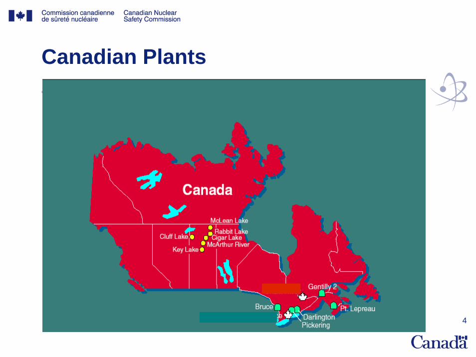
Canadian Plants
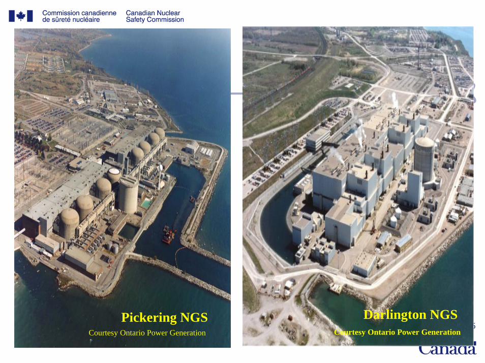
5Darlington NGS
Courtesy Ontario Power GenerationPickering NGS
Courtesy Ontario Power Generation
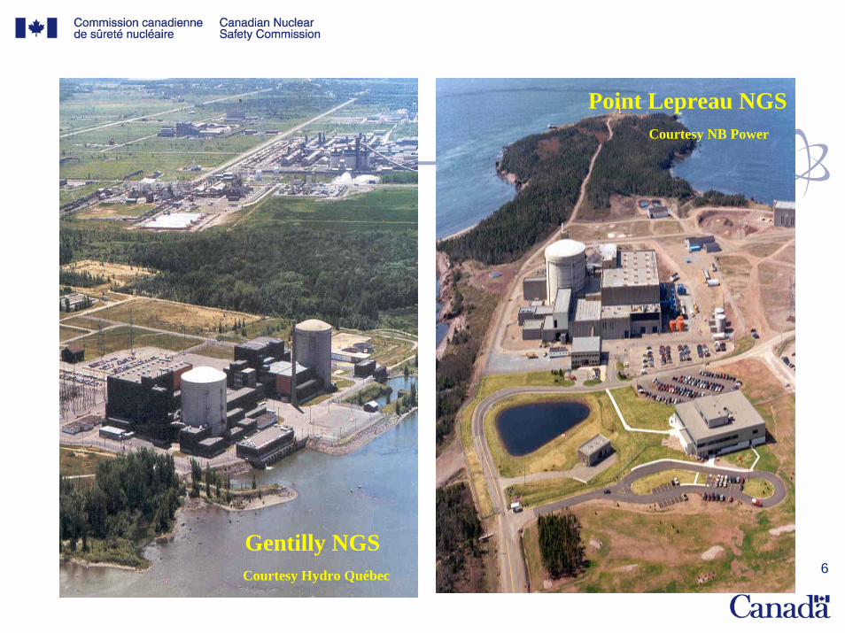
6
Point Lepreau NGSCourtesy NB Power
Gentilly NGSCourtesy Hydro Québec
7
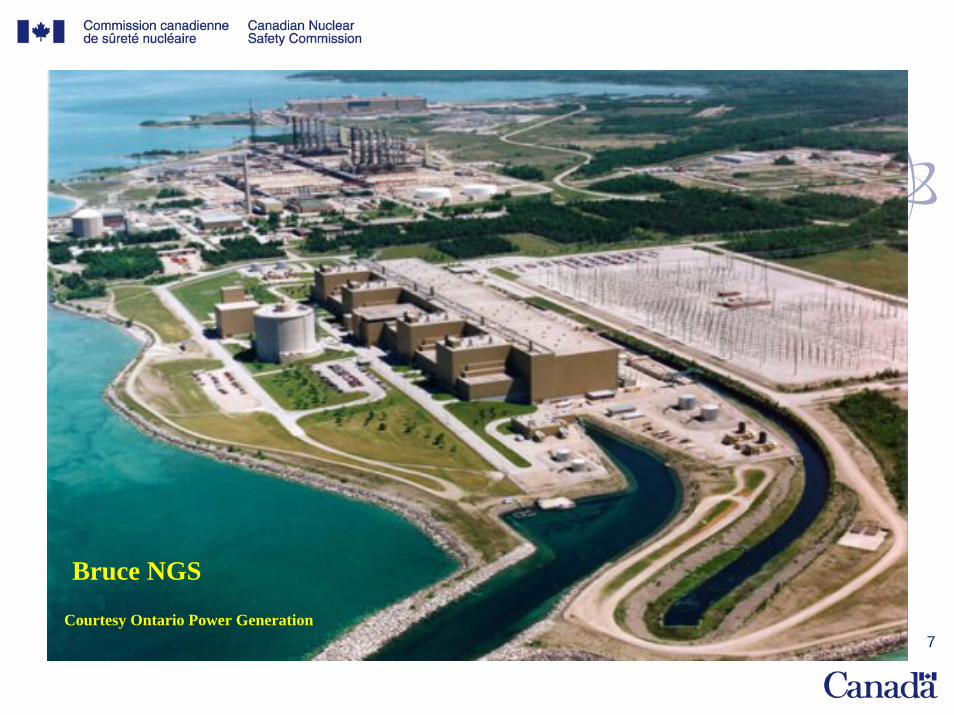
Bruce NGS
Courtesy Ontario Power Generation
8
The CANDU Plant
• CANDU = CANadian Deuterium-Uranium• Cooled and moderated by heavy water• Natural uranium fuel• D less effective moderator than H
larger separation between fuel bundles than in a LWR designers chose to have individually cooled channels about one bundle thick with heavy water moderator surrounding the channel

9
NSSS – PHWR & PWR

10
CANDU 6 Reactor Coolant System

11
CANDU PlantCandu 6 Fuel Bundle
12
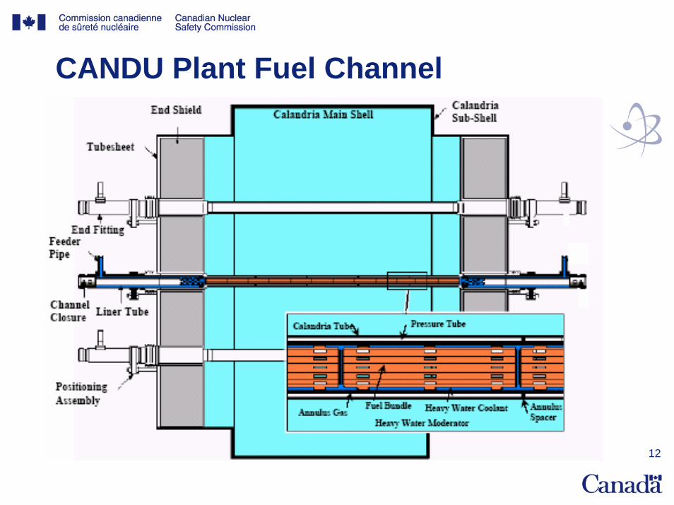
CANDU Plant Fuel Channel
13
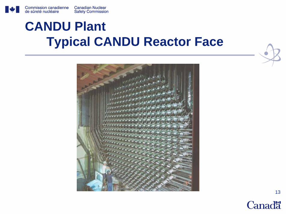
CANDU PlantTypical CANDU Reactor Face

14
PHWR & PWRReactor Assembly
15
Advanced CANDU Reactor ACR-700
• Builds on CANDU 6 design, project and operational experience
• Retained traditional CANDU features:– Modular horizontal fuel channel– Fuel bundle design– Low temperature, low pressure heavy water moderator– On-power fueling– Passive shutdown systems in low pressure moderator

16
Main ACR-700 New Design Features
• Main new features– Use of slightly enriched fuel (2%)– Light water coolant– Higher pressures of reactor coolant and main
steam – CANFLEX fuel bundle– Passive safety features added (e.g. gravity
supply of emergency feedwater)– Dry containment– Use of distributed control systems (DCS)
17
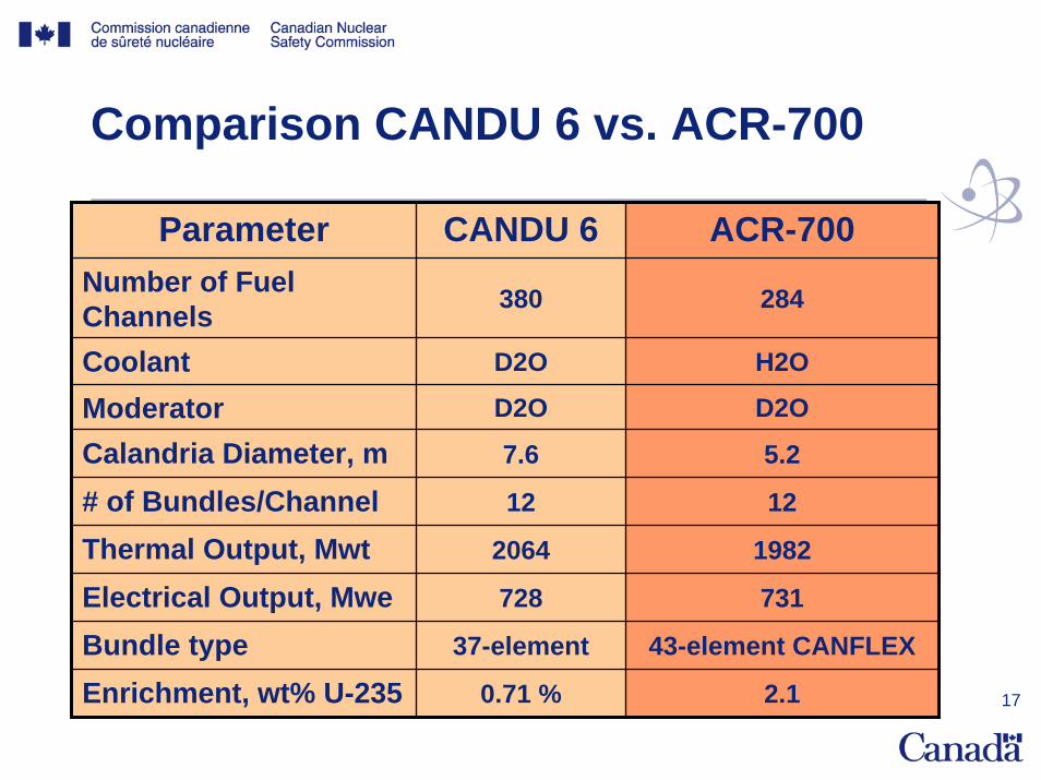
Comparison CANDU 6 vs. ACR-700
Parameter CANDU 6 ACR-700Number of Fuel Channels 380 284
Coolant D2O H2O
Moderator D2O D2O
Calandria Diameter, m 7.6 5.2
# of Bundles/Channel 12 12
Thermal Output, Mwt 2064 1982
Electrical Output, Mwe 728 731
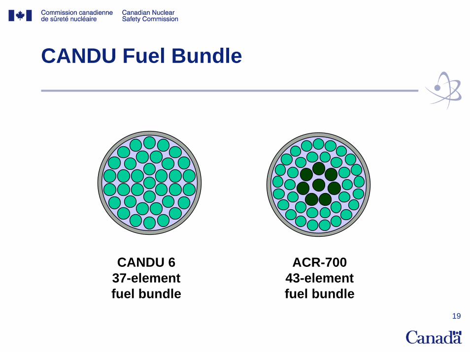
Bundle type 37-element 43-element CANFLEX
Enrichment, wt% U-235 0.71 % 2.1
18
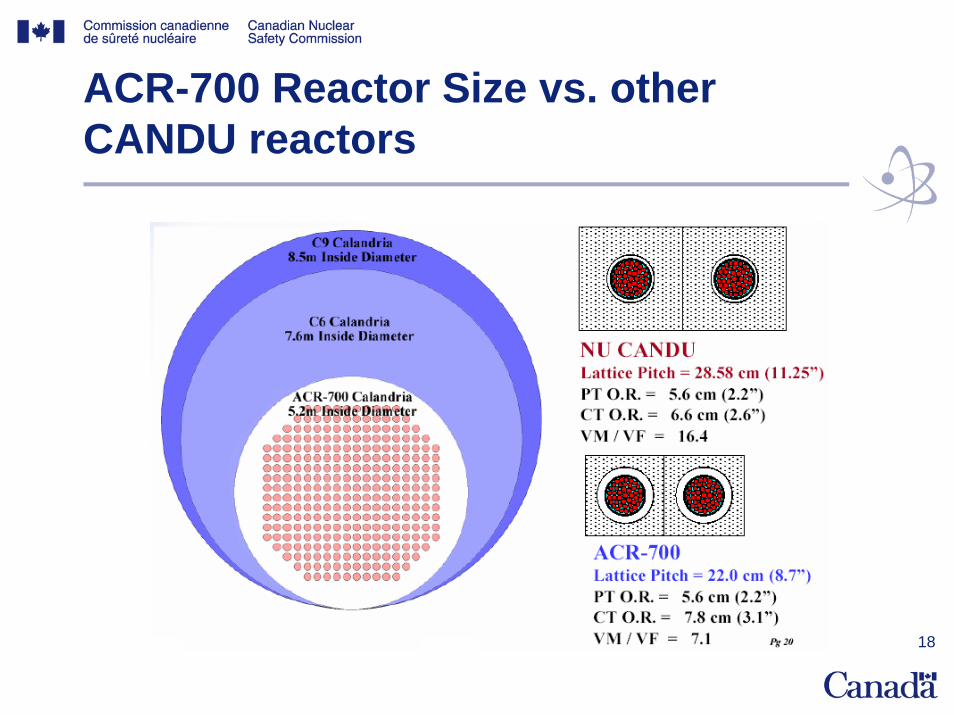
ACR-700 Reactor Size vs. other CANDU reactors
19
CANDU Fuel Bundle
CANDU 6 37-elementfuel bundle
ACR-70043-elementfuel bundle
20
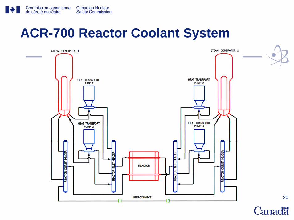
ACR-700 Reactor Coolant System

21
ACR-700 Reactor Coolant System
22
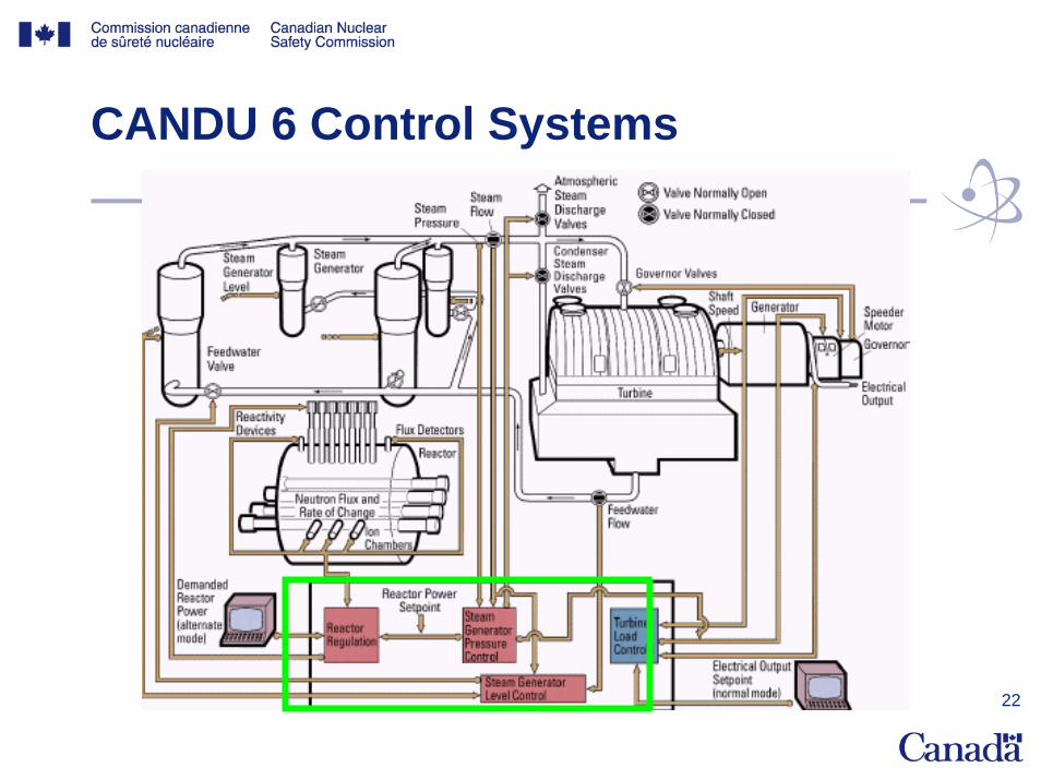
CANDU 6 Control Systems

23
CANDU Control SystemsReactor Regulating System
• Manoeuvres reactor power according to specified setpoints
• Provides rapid power reduction during serious plant upsets
• Responds to operator’s requests (power changes and shutdown)
• Action normally initiated by digital control computer (DCC)

24
Reactor Regulating System Reactivity devices
• Zone controllers – cylindrical tanks which can be filled or emptied with light water
• Adjuster rods – can only be driven slowly• Mechanical control absorbers – driven slowly or
dropped• Shutoff rods – driven out (by the RRS)• Liquid poison – added to the moderator• Refueling
• ACR-700: – no adjusters– H2O zone controllers are replaced by solid
control assemblies
25
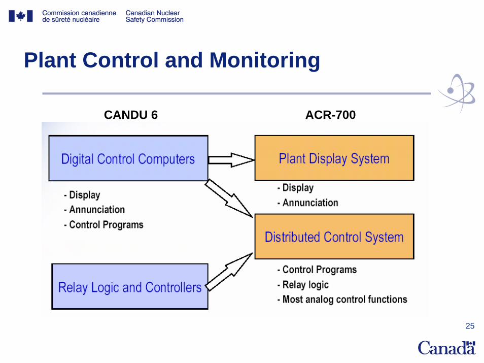
Plant Control and Monitoring
CANDU 6 ACR-700

26
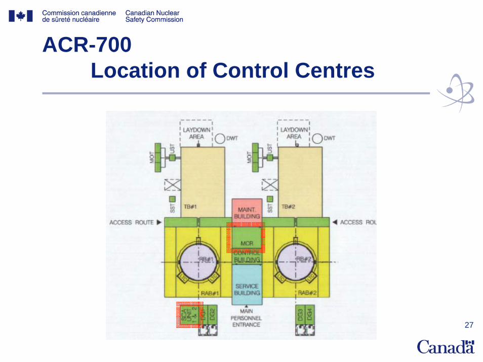
CANDU Control Centers
• Main Control Room (Group 1)– Controls and setpoints– Primary control of process and safety systems for all
DBEs– Testing of safety systems– On-line refueling
• Secondary Control Area (Group 2)– Separated from MCR– Required when MCR becomes uninhabitable– Controls provided for safety shutdown, heat sink and
monitoring of essential safety functions
27
ACR-700 Location of Control Centres

28
CANDU On-Line Refuelling
29
CANDU 6 Electrical Systems
• 4 classes of power according to availability requirements:– Class I – Uninterruptible DC for essential auxiliaries,
control, protection and safety equipment– Class II - Uninterruptible AC for essential auxiliaries,
control, protection and safety equipment– Class III – AC to essential auxiliaries that can tolerate
short duration power outages– Class IV - Normal AC to auxiliaries and equipment
which can tolerate long duration interruptions – EPS (emergency power system) – backup for Group 2
safety systems

30
ACR-700 Electrical Systems
• Classes I, II and III are now seismically qualified• No Emergency Power System (EPS)
31
Electrical Systems Odd end Even concept
• All voltage levels divided into odd and even buses
• Loads connected such that half of power to a process is supplied from odd bus and other half by even bus
• Separation requirements between odd and even systems (raceways, JB’s, etc)
32
Design Basis EventsCNSC C-6 Guide
• C-6 Guide for the Safety Analysis of CANDU Nuclear Power Plants– Provides guidelines for developing a safety
analysis report for CANDU plants– Establishes a “safety goal”– Covers practices and performance criteria
for safety analysis– Not mandatory

33
Design Basis EventsCNSC C-6 guidelines
• C-6 uses five classes of events based on likelihood • Initiating events are generally included for Class 1, 2
& 3:– Class 1: control failures, normal electrical power
failures, ….– Class 2: small loss of reactor primary coolant, ….– Class 3: large loss of reactor primary coolant, ….–
• Class 4 and 5 generally include combinations of events, in particular combinations of initiating events and total failure of a safety system
34
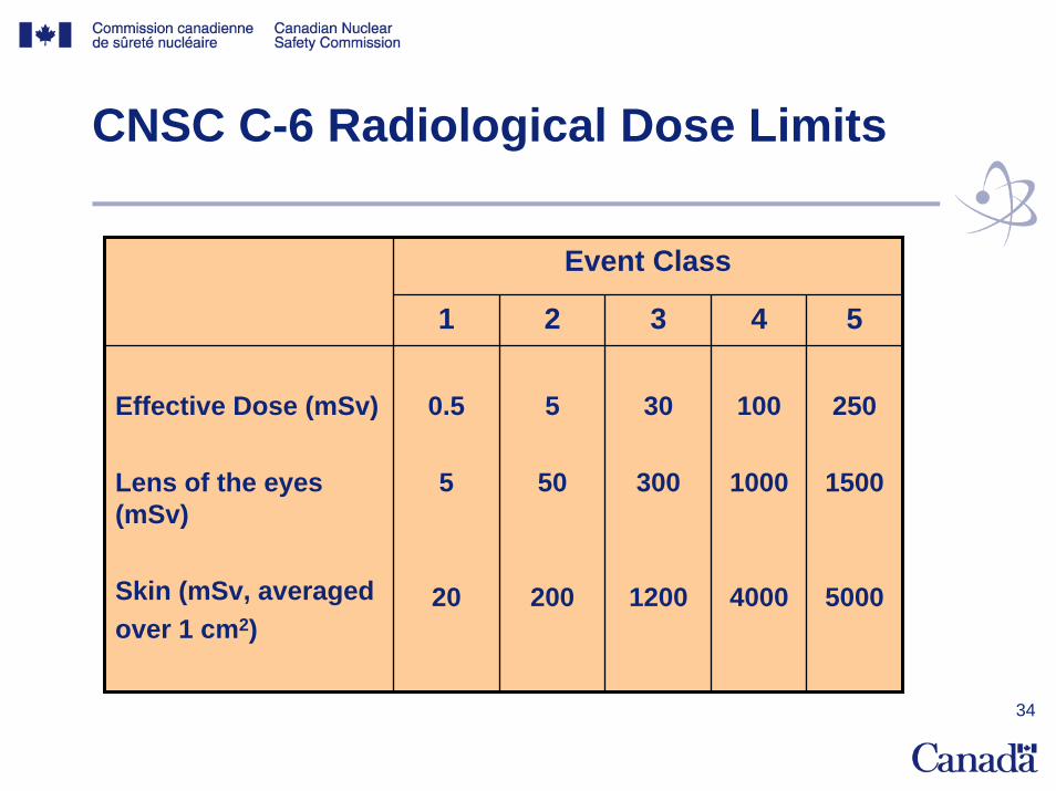
CNSC C-6 Radiological Dose Limits
Event Class
1 2 3 4 5
Effective Dose (mSv)
Lens of the eyes (mSv)
Skin (mSv, averagedover 1 cm2)
0.5
5
20
5
50
200
30
300
1200
100
1000
4000
250
1500
5000
35
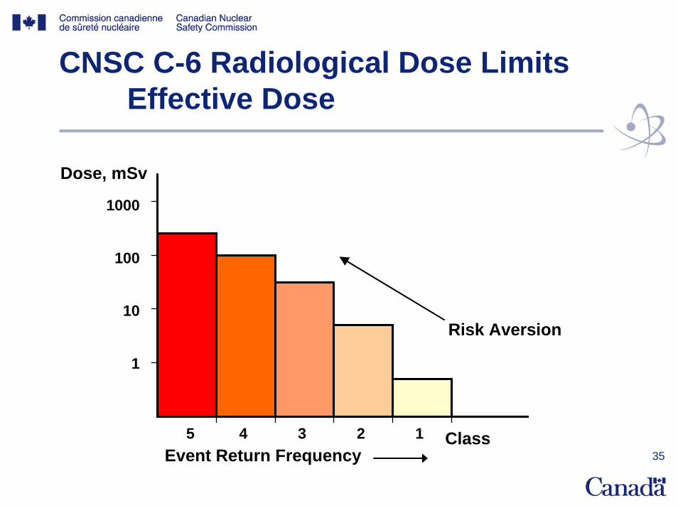
CNSC C-6 Radiological Dose LimitsEffective Dose
Class5 4 3 2 1
1000
100
10
1
Risk Aversion
Event Return Frequency
Dose, mSv
36
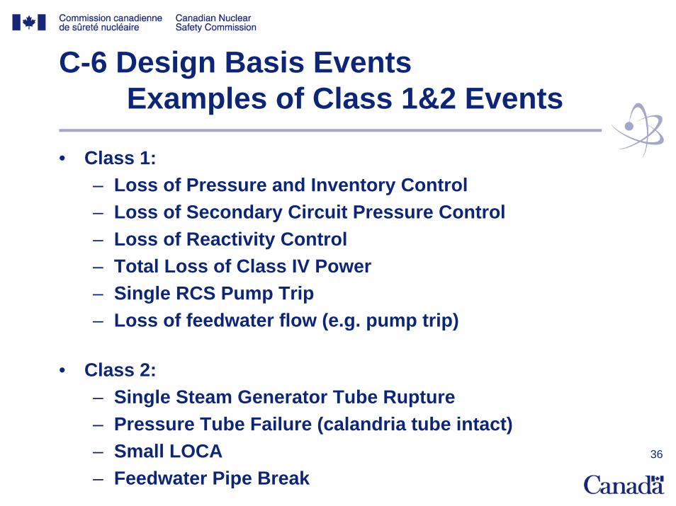
C-6 Design Basis EventsExamples of Class 1&2 Events
• Class 1:– Loss of Pressure and Inventory Control– Loss of Secondary Circuit Pressure Control– Loss of Reactivity Control– Total Loss of Class IV Power– Single RCS Pump Trip– Loss of feedwater flow (e.g. pump trip)
• Class 2:– Single Steam Generator Tube Rupture– Pressure Tube Failure (calandria tube intact)– Small LOCA– Feedwater Pipe Break
37
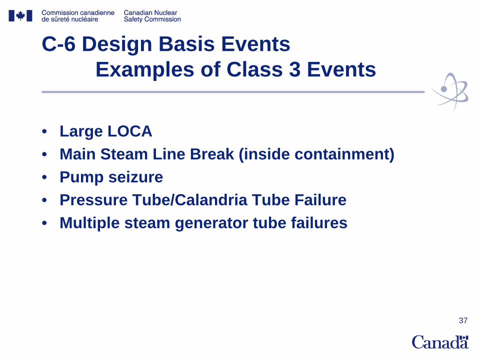
C-6 Design Basis EventsExamples of Class 3 Events
• Large LOCA• Main Steam Line Break (inside containment)• Pump seizure• Pressure Tube/Calandria Tube Failure• Multiple steam generator tube failures
38
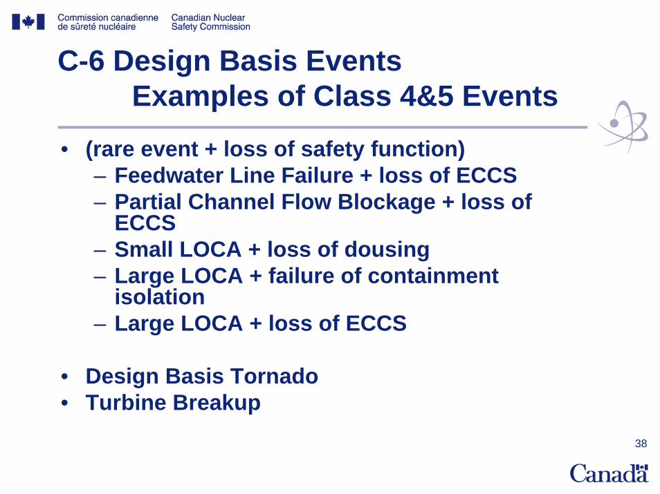
C-6 Design Basis EventsExamples of Class 4&5 Events
• (rare event + loss of safety function)– Feedwater Line Failure + loss of ECCS– Partial Channel Flow Blockage + loss of
ECCS– Small LOCA + loss of dousing – Large LOCA + failure of containment
isolation– Large LOCA + loss of ECCS
• Design Basis Tornado • Turbine Breakup
39
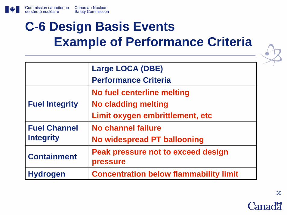
C-6 Design Basis EventsExample of Performance Criteria
Large LOCA (DBE) Performance Criteria
Fuel IntegrityNo fuel centerline meltingNo cladding meltingLimit oxygen embrittlement, etc
Fuel Channel Integrity
No channel failureNo widespread PT ballooning
Containment Peak pressure not to exceed design pressure
Hydrogen Concentration below flammability limit
40
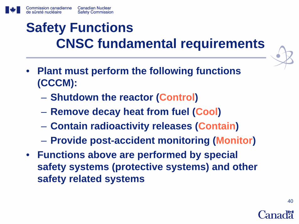
Safety FunctionsCNSC fundamental requirements
• Plant must perform the following functions (CCCM):– Shutdown the reactor (Control)– Remove decay heat from fuel (Cool)– Contain radioactivity releases (Contain)– Provide post-accident monitoring (Monitor)
• Functions above are performed by special safety systems (protective systems) and other safety related systems
41
Two-Group Separation
• Purpose: to ensure that common-cause events will not prevent plant from performing required safety function
• Systems are grouped into 2 groups • Groups are independent of each other and
physically separated • Systems in each group can provide the
essential safety functions independent of the other group
42
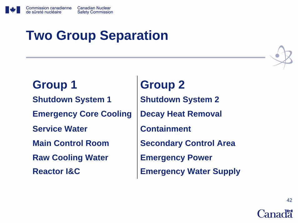
Two Group Separation
Group 1 Group 2Shutdown System 1 Shutdown System 2Emergency Core Cooling Decay Heat Removal
Service Water Containment
Main Control Room Secondary Control Area
Raw Cooling Water Emergency PowerReactor I&C Emergency Water Supply
43
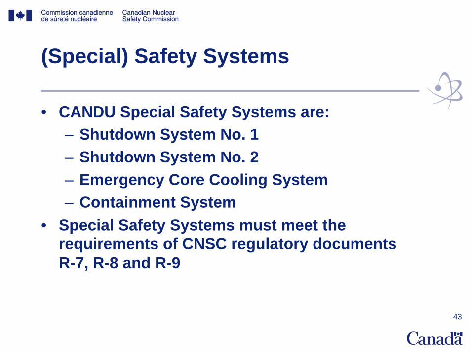
(Special) Safety Systems
• CANDU Special Safety Systems are:– Shutdown System No. 1– Shutdown System No. 2– Emergency Core Cooling System– Containment System
• Special Safety Systems must meet the requirements of CNSC regulatory documents R-7, R-8 and R-9

44
Special Safety Systems
• CNSC Regulatory documents R-7, R-8, R-9 require:– SSS be independent of each other in design and
operation– SSS be independent from process systems– SSS have unavailability of 0.001– SSS perform their intended functions while subject to
the most severe environmental conditions resulting from DBEs (EQ)
– Status of equipment required for SSS actuation be monitored from the control room
– Availability tests be performed to demonstrate compliance with availability requirements
– (other)

45
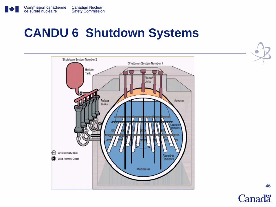
CANDU Shutdown Systems
• SDS1 is separate and diverse from SDS2– design based on different physical principles
– SDS1: Dropping of mechanical shutoff– SDS2: Injection of gadolinium nitrate
– independent sensors– diverse hardware
• Each system covers the whole spectrum of design basis events
46
CANDU 6 Shutdown Systems

47
ACR-700 Shutdown System No. 2
48
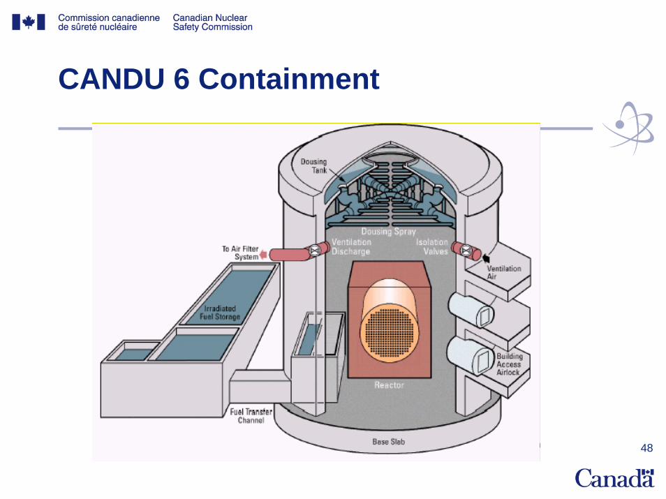
CANDU 6 Containment
49
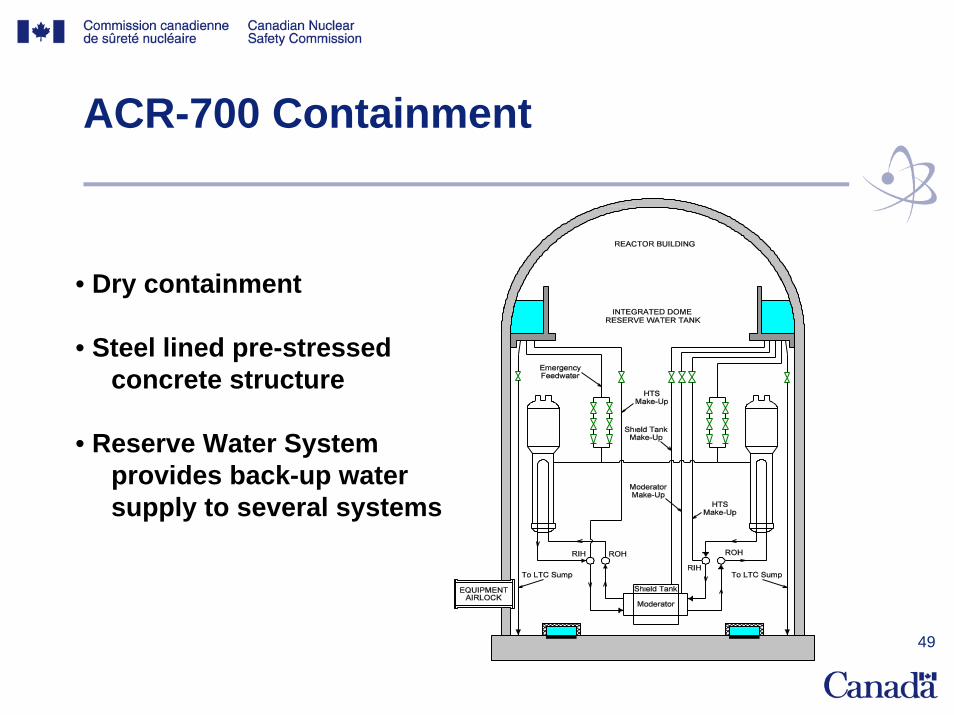
ACR-700 Containment
• Dry containment
• Steel lined pre-stressed concrete structure
• Reserve Water System provides back-up water supply to several systems

50
CANDU 6 Emergency Core Cooling
51
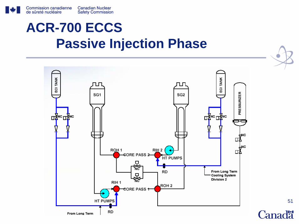
ACR-700 ECCSPassive Injection Phase
52
ACR-700USNRC Pre-Application Review
• http://www.nrc.gov/reactors/new-licensing/license-reviews/design-cert/acr-700.html