design proposal - michigan technological...
TRANSCRIPT

Design ProposalFA4740 Loudspeaker Construction Project
prepared by:Kevin C. Dixon
12/17/2007

I. Introduction and Functional GoalsDesigning a pair of loudspeakers to serve effectively in multiple uses and environments is a challenging undertaking. Discovering exactly how to design the speakers can be better understood if the requirements of the listener are known.
A. Functional DescriptionThe end user (me) requires a pair of speakers that will primarily be used for home enjoyment listening, but also should be able to double as acceptable monitoring speakers for working on various audio projects. These two requirements demand the ability to play at ~85dB SPL and have a wide bandwidth. I chose the SPL level based on my past experience with mixing systems. 85dB SPL is loud enough for various activities that require rocking out (cleaning the house, building stuff out of wood, listening to a new album, etc) and is also a recommended level for mixing. Additionally, I will be moving soon, and so want the speakers reasonably compact and easy to transport.
B. Balancing the “Pie”In John L. Murphy's book Introduction to Loudspeaker Design he presents the idea of the trade-offs between Sound Pressure Level, Size, and Bandwidth. Of the various templates he described, I want my speakers to fall into his “Hi-Fi” category1. In his example, he describes speakers of this type to have about a 90dB sensitivity, f(3) at 40Hz, and be approximately 1 cubic foot in volume. Speakers of this variety emphasize bandwidth at the expense of SPL and size. Though keeping size to a minimum is high on my list of priorities, 1 cubic foot is within the acceptable range.
C. Functional GoalsGiven the requirements in the functional description, and the findings from the trade-off pie, the following list of qualities (ranked in order of importance) describes the features the desired.
1. Fit in Budget Constraints ($300)2. Portability (able to carry one speaker unassisted and easily)3. Wide Bandwidth (f(3) of at least 40Hz)4. High Fidelity/Accuracy5. 85dB SPL (+18dB crest factor = 103dB)6. Aesthetically Pleasing
II. DriversA. General Considerations
Approximately 50% of the 300 dollar budget was to be allocated to drivers, which means a budget of about $75 for drivers per speaker. When selecting the general system configuration and drivers for this project, care was taken to stay within this budget. With only $75 per speaker for drivers, the idea of a three-way system was quickly eliminated, since entry level sub-woofers start at about 50 dollars each, which would leave little money for mid-range and tweeter. Also, having a sub-woofer would either result in very large tower speakers, or even more speaker boxes, violating the second functional goal (portability) as well. To replace having no sub-woofers, a vented enclosure will be used to achieve a greater bandwidth.
B. Mid-Bass DriverBy settling on a two-way system, the biggest problem becomes achieving low frequency extension. This rules out most drivers smaller than 6” in diameter for the mid-bass driver, since these speakers typically have an fs that is too high. 8” and larger drivers are still prohibitively expensive, and also tend to require more enclosure volume than allowed by the functional goals. Many 6-7” drivers have fs ratings that allow them to reach somewhat lower frequencies, and are also available at a lower price
Design Proposal 1

point that leaves enough money for suitable tweeters to be had as well.Two drivers were initially considered as prime candidates, with a third being considered later when it went on sale. Table I below summarizes some of their key characteristics.
Table I: Prime Mid-Bass Driver Candidates
Driver Price Diameter fs Sensitivity Qts V(as)Vifa P17WJ00 $45.20 6.5” 37Hz 88dB 0.35 1.225 ft3
Hi-Vi F6 $45.65 7” 45Hz 88dB 0.35 0.579 ft3
Vifa MG18SK09 $54.70* 7” 27.8Hz 89dB 0.233 2.461 ft3
* currently on sale for $29.00
These three drivers were simulated in 4th order vented enclosures using the software package WinSpeakerz to try and optimize low frequency extension while maintaining a flat theoretical response. These enclosure frequency response graphs can be seen in Appendix A.The Vifa MG18SK09 was eliminated for two key reasons. First, it is at least $10 too expensive. Secondly, it appears to be harder to control in the box, as well as requiring a significantly larger box volume. (see Appendix A/Figure 13)The Hi-Vi F6 has a very flat frequency response in its ideal frequency response range, however, its “high” resonant free air frequency and small V(as) value prevent it from achieving the low-frequency extension desired (see Appendix A). Note also that the F6 has more consistent off-axis response, probably due to its phase-plug.The Vifa P17WJ00 has a pretty smooth response curve, but has about a 1dB boost from 1kHz to 5kHz. As can be seen in Table I, it features a remarkably low fs value for drivers of this size, and has a V(as) that makes it a good performer in terms of low-frequency extension.These two drivers are not without their faults. In the high-frequency range, the Hi-Vi driver has two distinct peaks (at 3 and 4kHz), likely the result of the stiffer Kevlar/Paper material. The P17WJ00 also features a bit of a peak at around 2kHz, for the same reasons. In its favor, however, is its somewhat more compliant cone material. Because of this, the peaks are not as pronounced, and should be
Design Proposal 2
Figure 1: Hi-Vi F6 Frequency Response
Figure 2: Vifa P17WJ00 Frequency Response

easier to deal with in the crossover. (see sections II.C. and III.B.).The Loudspeaker Design Selection Guide2 doesn't have anything in particular to say about the Vifa P17WJ00, neither good nor bad, but it is on their recommended list. However, the LDSG recommends the Hi-Vi F6 for the reasons discussed above (flat frequency response, very good numbers for reflex enclosures, etc). Regrettably, the Hi-Vi F6 is not acceptable due to its lack of low-frequency extension, when compared to the Vifa P17WJ00.
I select the Vifa P17WJ00 for my mid-bass driver.
C. TweeterTo start my search for a tweeter, I knew I needed a tweeter that could be easily crossed over with the Hi-Vi F6. Also, it would need to provide good frequency response as far as possible up to 20kHz, to try and keep with my wide bandwidth and fidelity goals. Also, the cost of the mid-bass driver leaves about $30 to spend. These requirements generally reduce my selection of tweeters to 1” dome tweeters. I chose to avoid metal dome tweeters, since metal domes in my price range suffer from issues with cone breakup in the higher frequency bands (10k-20k).A wide variety of textile dome tweeters can be had at the $30 price point. Table II below summarizes some potentially applicable tweeters.
Table II: Specification Comparison of 1” Textile Dome Tweeters
Driver Price fs Sensitivity LDSGSeas 27TDF $26.35 900Hz 91dB n/aSeas 27TDC $32.05 550Hz 90dB n/aSeas 27TFFC $31.10 900Hz 91dB “...Seas best buy”Vifa D27TG35 $28.15 650Hz 91dB Note 1Vifa D27TG45 $28.25 650Hz 91dB Note 1,2Vifa DX25TG05 $27.75 650Hz 93.5dB “an excellent unit”
Note 1: The LDSG only “conditionally recommends” the D27TG35 and 45 because current production units do not have an fs that complies with the published specifications, being ~900Hz.
Note 2: LDSG notes that the slightly bulged face plate of the D27TG45 provides pseudo-horn loading, helping to reduce diffraction.
To compare the tweeters further, I compared the frequency responses. Of the three drivers from Seas, the TDC has a strange lump in the 1.5-2kHz range, but is pretty smooth from 3-10kHz (Figure 3). Also, there is a peak around 14kHz, followed by a dip, then another peak at about 17kHz. The TDC rolls off on the low end at about -6dB/octave 200Hz to 1.5kHz.Seas' 27TDF has a quite flat response from 1.5-15kHz (+/- 1dB) and has the highest sensitivity, and approximately a -10dB/octave low end roll off, starting at about 1kHz (Figure 4). The
Design Proposal 3
Figure 3: Seas 27TDC Frequency Response

27TDF seems to be a pretty good bargain overall, but would prove hard to crossover. Both the TDC and TDF are somewhat newer, and so the LDSG has no remarks about them, however the TDC especially has found some favor on different DIY forums.The Seas 27TFFC is strongly recommended by the LDSG for a balance between performance and cost. It has about a -6dB/octave roll off from 2kHz down to 300Hz, which should make it fairly easy to crossover (Figure 5). It also has a quite flat frequency response in its usable range; from 2kHz to 10kHz, there are only variations of +/- 1dB max. The 27TFFC also has the best off-axis response of the Seas drivers. I consider this driver to be the strongest of the Seas drivers.
Figure 4: Seas 27TDF Frequency Response Figure 5: Seas 27TFFC Frequency Response
Vifa's D27TG35 and 45 are very similar drivers in terms of their frequency response. The D27TG45's response is shown in Figure 6 for reference. The main difference is that the 45 features a bulged ring around the edge of the tweeter in order to help limit diffraction; it also shows slightly smoother off-axis response. Both of these drivers start to roll off -3dB per octave starting at 2kHz, and have very flat response. The 45 fluctuates less than +/- 1dB, while the 35 fluctuates just over +/- 1dB. The only real disadvantage to these are the -3dB roll off, which would make it easy to produce an asymmetrical crossover curve, but difficult to produce a good crossover with.
Design Proposal 4
Figure 7: Vifa D27TG45 Frequency Response Figure 6: Vifa DX25TG05 Frequency Response

The Vifa DX25TG05 (Figure 7) was originally only produced for OEMs. It is a very high performance driver for the price. There is about a 2dB loss on frequencies above 10kHz, but has very good 30° off axis response (a smooth curve, with a -5dB shelf above 10kHz). On the low end, it features a -6dB per octave loss, starting at 1kHz. It would seem easy to crossover, however comments on the LDSG and elsewhere indicate that crossover design is not so straight forward as it may seem with this driver.Between the Seas 27TFFC and the Vifa DX25TG05, I prefer the Seas 27TFFC. As this is my first full-range loudspeaker venture, I am basing this off of the assumption that it will be easier to crossover appropriately. The $3 difference is not a big deal to me, and that $3 would probably be spent on the tweeter compensation, since it is another 3dB higher in sensitivity than the Seas driver.
I select the Seas 27TFFC as my tweeter.
III.CrossoverA. ConsiderationsThere are several considerations to be taken into account when selecting a crossover point. Common sense would tell us that we would want to avoid any discontinuity or coloration at the point where the human ear is most sensitive. Research done over the past 80 years on how humans perceive the intensities of different frequency bands can help us determine where the ear is most sensitive. This information has been distilled into ISO specification 226:2003, which provides charts known as the Equal-Loudness Contours.3 According to these curves, the most sensitive frequency band for the average human is in the 3-4kHz range.4 So, in order to avoid possible discoloration that would be easily sensed, it is advisable to select a crossover point either above or below this range.
B. Crossover PointCrossing over your drivers at a higher frequency typically makes for higher power handling, since the tweeter is not so taxed, while a lower frequency generally provides more clarity, since the mid-bass isn't being asked to go so high, where the tweeter can perform better.5 As described in Section I.C., clarity and accuracy have a higher priority than power handling in this design, so a lower crossover point is preferable.Once these initial considerations have been mulled over, the real answer lies in what the drivers are capable of and where they perform best. In order to crossover the Hi-Vi F6 mid-bass with the Seas 27TFFC tweeter, we need to compare frequency response charts (found in Appendix B).Though I wasn't planning on it, we can quickly see that it would be impractical to crossover the mid-bass above the 3-4kHz sensitive zone, since its response quickly becomes unpredictable above 4kHz. The tweeter, as discussed in II.C., has a natural -6dB roll off starting at 2kHz. To take advantage of this quality, I plan to use an asymmetrical crossover circuit, using a 2nd order low pass filter on the mid-bass and a 1st order high pass filter on the tweeter (which, combined with the 1st order natural roll off, results in a 2nd order roll off). The -3dB point on a roll-off curve is considered to be the corner frequency of a filter. On the 27TFFC, this -3dB occurs at almost exactly 1,500Hz. Of special note, according to some texts, is that crossover corner frequency may have to be varied on the high pass and low pass in order to get correct summation.6
Design Proposal 5Figure 8: Crossover Circuit Diagram
Selecting 1,500Hz is advantageous in several ways. First, it employs the natural roll off of the tweeter, which provides about a $10 savings on inductor costs (per speaker). The P17WJ00 mid-bass has a +1dB “mesa” from about 1.8-2.5kHz. If the woofer is crossed over at 1.5kHz, with a -12dB per octave slope, the first 500Hz from 1-1.5kHz of the filter will give a -3dB drop at 1.5kHz, while the frequency response starts to rise to +1dB, the filter continues to be more subtractive while the frequency response stays level. Based on this information, the +1dB mesa should not significantly interfere with the crossover in such a way that could cause comb-filtering with the tweeter.
C. TopologyAs mentioned in III.B. above, the crossover will be a 2nd order/1st order Butterworth design. Additionally, the selected tweeter has 3dB greater sensitivity than the mid-bass driver. The tweeter will be attenuated by 3dB, using a simple combination of resistors. Figure 8 details the circuit diagram of the crossover and attenuator.It is important to note that since the low pass filter is 2nd order, the phase may be reversed compared to the high pass filter/tweeter. If this becomes the case, swapping the connection of the positive and negative terminals will rectify this problem.As discussed in Newell's Loudspeakers, bi-wiring or bi-amping a speaker enclosure can provide gains.7
To be compatible with this vein of thought, changing the crossover design to include a separate input for each segment of the filter. See Section IV.A. for information on how this will be implemented.
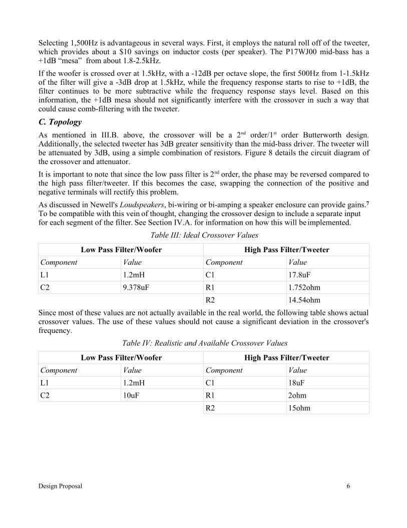
Table III: Ideal Crossover Values
Low Pass Filter/Woofer High Pass Filter/TweeterComponent Value Component ValueL1 1.2mH C1 17.8uFC2 9.378uF R1 1.752ohm
R2 14.54ohmSince most of these values are not actually available in the real world, the following table shows actual crossover values. The use of these values should not cause a significant deviation in the crossover's frequency.
Table IV: Realistic and Available Crossover Values
Low Pass Filter/Woofer High Pass Filter/TweeterComponent Value Component ValueL1 1.2mH C1 18uFC2 10uF R1 2ohm
R2 15ohm
Design Proposal 6
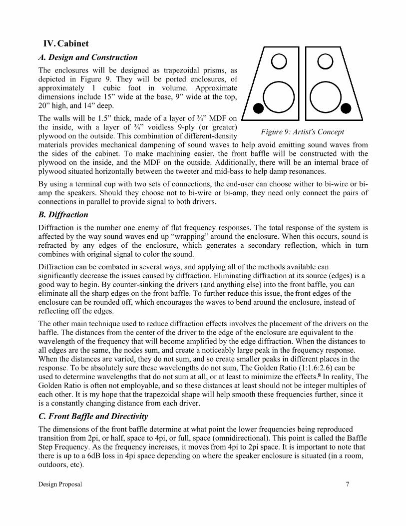
IV. CabinetA. Design and ConstructionThe enclosures will be designed as trapezoidal prisms, as depicted in Figure 9. They will be ported enclosures, of approximately 1 cubic foot in volume. Approximate dimensions include 15” wide at the base, 9” wide at the top, 20” high, and 14” deep.The walls will be 1.5” thick, made of a layer of ¾” MDF on the inside, with a layer of ¾” voidless 9-ply (or greater) plywood on the outside. This combination of different-density materials provides mechanical dampening of sound waves to help avoid emitting sound waves from the sides of the cabinet. To make machining easier, the front baffle will be constructed with the plywood on the inside, and the MDF on the outside. Additionally, there will be an internal brace of plywood situated horizontally between the tweeter and mid-bass to help damp resonances.By using a terminal cup with two sets of connections, the end-user can choose wither to bi-wire or bi-amp the speakers. Should they choose not to bi-wire or bi-amp, they need only connect the pairs of connections in parallel to provide signal to both drivers.
B. DiffractionDiffraction is the number one enemy of flat frequency responses. The total response of the system is affected by the way sound waves end up “wrapping” around the enclosure. When this occurs, sound is refracted by any edges of the enclosure, which generates a secondary reflection, which in turn combines with original signal to color the sound.Diffraction can be combated in several ways, and applying all of the methods available can significantly decrease the issues caused by diffraction. Eliminating diffraction at its source (edges) is a good way to begin. By counter-sinking the drivers (and anything else) into the front baffle, you can eliminate all the sharp edges on the front baffle. To further reduce this issue, the front edges of the enclosure can be rounded off, which encourages the waves to bend around the enclosure, instead of reflecting off the edges.The other main technique used to reduce diffraction effects involves the placement of the drivers on the baffle. The distances from the center of the driver to the edge of the enclosure are equivalent to the wavelength of the frequency that will become amplified by the edge diffraction. When the distances to all edges are the same, the nodes sum, and create a noticeably large peak in the frequency response. When the distances are varied, they do not sum, and so create smaller peaks in different places in the response. To be absolutely sure these wavelengths do not sum, The Golden Ratio (1:1.6:2.6) can be used to determine wavelengths that do not sum at all, or at least to minimize the effects.8 In reality, The Golden Ratio is often not employable, and so these distances at least should not be integer multiples of each other. It is my hope that the trapezoidal shape will help smooth these frequencies further, since it is a constantly changing distance from each driver.
C. Front Baffle and DirectivityThe dimensions of the front baffle determine at what point the lower frequencies being reproduced transition from 2pi, or half, space to 4pi, or full, space (omnidirectional). This point is called the Baffle Step Frequency. As the frequency increases, it moves from 4pi to 2pi space. It is important to note that there is up to a 6dB loss in 4pi space depending on where the speaker enclosure is situated (in a room, outdoors, etc).
Design Proposal 7
Figure 9: Artist's Concept
The Baffle Step Frequency can be calculated using the following equation.9 Note that the frequency calculated is the frequency for 3dB of loss, the corner frequency of the “filter”.
f3=380Wb
where Wb is the width of the baffle in feet.
For a rectangular baffle, there are two baffle step frequencies. For my enclosure, assuming the baffle were to be rectangular, the two frequencies will be
457.83Hz = 380 / 0.83 and 227.54Hz = 380 / 1.67Given these frequencies, the Baffle Step Response will have two ridges. We also know that the speaker will not be very directional below ~500Hz, and will certainly be radiating omnidirectionally below 200Hz. This loss can be minimized if the speakers are placed close to a wall. The 27TFFC tweeter has a dome diaphragm, which provides almost no pattern control, however it will be directional because all of the frequencies supplied by the tweeter will be in 2pi space. (1500Hz = ~9in).Some directivity characteristics (for the tweeter) are affected by the off-axis response. As seen in Appendix B/Figure 15, the tweeter begins to lose significantly above 10kHz in 30° off-axis response, and loses heavily above 5kHz in 60° off-axis response. This off-axis loss helps keeps the sound more focused, though below 5kHz the only directivity will be from the aforementioned baffle.Given these characteristics, the speakers should have more of a “wash” of sound than any “beaming” characteristics. This is desirable in an enjoyment speaker, because frequently the listener will not be in the “sweet spot”, but will at least be in front of the speakers.
D. Low-Frequency TuningAs mentioned briefly in Section II.A. the cabinet will be tuned as a 4th order bass reflex enclosure. This is done to extend the low frequency response. Compare Figure 10 below with the Figure 11 in Appendix A to see the gains in low frequency extension. I plan to configure my enclosures with a pair of smaller ports rather than one larger one to reduce the velocity of air moving, which can add coloration to the sound. Note that this differs from the artist's concept in Figure 9. There would be a smaller port on either side of the mid-bass driver.As noted in Appendix A/Figure 11, the F(B) of the enclosure will come out to be 44Hz, which combines with the frequency response of the driver to create a fairly smooth response down another octave when compared to the response of Figure 10. Another important item to note in Figure 11 is the plotted excursion. When simulated with 40W of input power, the excursion of the driver does not exceed its Xmax until below 38Hz. It does however nearly peak at 60Hz, with only a few tenths of a millimeter to spare. Though these facts seems troubling, in practice they generally do not pose a threat to the physical well-being of the driver.
Design Proposal 8

V. ConclusionAfter determining desired drivers, crossover design, and enclosure construction, I estimate I should come in at about $340 for the pair of speakers. This is an acceptable overage for me, since I can afford it, and it should be well worth it to have the dual-material enclosure walls, as opposed to just MDF. Of particular note is the fact that these speakers will be fairly heavy, but still easily movable by a single person. The speakers will have an f(3) of about 42Hz, which is pretty close to the desired specifications.The speakers should have an overall sensitivity close to 85dB. To achieve the crest-factor goal of +18dB (103dB total) would require 64 watts of input power. As we know from Figure 11, this would probably destroy the mid-bass driver. If we settle for a +15dB crest-factor (100dB) total, the input power requirement is dropped to about 32W, and lets us avoid both mechanical and electrical overages. The driver selection and a well designed crossover should ensure that the system meets the goals for fidelity. Finally, the trapezoidal shape and outer layer of baltic birch should prove aesthetically pleasing.
Design Proposal 9
Figure 10: Vifa P17WJ00 in Sealed Box. V(B) = 0.3 cu. ft.

References
1. Murphy, John L. Introduction to Loudspeaker Design. Andersonville, TN: True Audio, 1998. pg 56.
2. Stout, Bob. "Section 2 - Hi-Fi Drivers and Vendors." Loudspeaker Design Selection Guide. 25 Mar. 2007. Snippets.Org. 30 Sept. 2007 <http://ldsg.snippets.org/sect-2.php>.
3. "Full Revision of International Standards for Equal-Loudness Level Contours (ISO 226)." 22 Oct. 2003. National Institute of Advanced Industrial Science & Technology. 1 Oct. 2007 <http://www.aist.go.jp/aist_e/latest_research/2003/20031114/20031114.html>.
4. Nave, Carl R. "Equal Loudness Curves." HyperPhysics. 2000. Department of Physics and Astronomy, Georgia State University. 26 Sept. 2007 <http://hyperphysics.phy-astr.gsu.edu/hbase/sound/eqloud.html>.
5. Plummer, Christopher. "Crossovers." MTU. FA4740. Walker 212, Houghton, MI. 25 Sept. 2007.
6. McCarthy, Bob. Sound Systems: Design and Optimization. 1st ed. Burlington, MA: Elsevier, 2007. pp. 91,98.
7. Newell, Philip, and Keith Holland. Loudspeakers: for Music Recording and Reproduction. Oxford, UK: Elsevier Ltd., 2007. pp 191-192.
8. Bednarek, Roman J. "Tweeter Diffraction." RJB Audio Projects. 30 Sept. 2007 <http://www.rjbaudio.com/Audiofiles/tweeter%20diffraction.html>.
9. Elliot, Rod. "Baffle Step Compensation." Elliot Sound Products. 2001. 29 Sept. 2007 <http://sound.westhost.com/bafflestep.htm>.
Design Proposal 10

Appendix A: Mid-bass Frequency Response in Vented Enclosures
See Section II.B. for driver parameters.
Design Proposal 11
Figure 11: Vifa P17WJ00 in 4th order vented enclosure.V(B) = 0.85 cu. ft. F(B) = 44 Hz P(in) = 40W
Figure 12: Hi-Vi F6 in 4th order vented enclosure.V(B) = 0.4 cu. ft. F(B) = 53.5 Hz P(in) = 40W

Design Proposal 12
Figure 13: Vifa MG18SK09 in 4th order vented enclosure.V(B) = 1.5 cu. ft. F(B) = 40 Hz P(in) = 40W

Appendix B: Selected Driver's Frequency Response Plots
Design Proposal 13
Figure 14: Vifa P17WJ00 Frequency Response
Figure 15: Seas 27TFFC Frequency Response