design specification for a sleepwear diagnostic...
TRANSCRIPT

November 17, 2011
Dr. Andrew Rawicz
School Of Engineering Science
Simon Fraser University
Burnaby, British Columbia
V5A 1S6
Re: ENSC 440 Design Specification for a Sleepwear Diagnostic System
Dear Dr. Rawicz:
Please find the attached Design Specification Document for a Sleepwear Diagnostic System (SDS) by
NAPNEA. NAPNEA is developing a sensor-equipped shirt that quantifies physiological phenomena that
occur during sleep and that can be used to diagnose sleep apnea. The SDS will provide an innovative
and reliable solution to existing sleep apnea diagnosis limitations.
Our design specification provides a thorough description of all technical aspects of the SDS First and
Second Generation Prototypes. This specification demonstrates how the SDS functional requirements
(delivered in the Functional Specification for a Sleepwear Diagnostic System document) will be satisfied.
This document also discusses the methods and procedures that will be used to test and verify the SDS.
NAPNEA is a well-rounded biomedical company comprised of five aspiring biomedical engineers: Alex
Manousiadis, Allison Chew, Ekin Nalbantoglu, Eleanor Li, and Jason Cheung. While each member
possesses a unique skill set, our fervent dedication to the biomedical engineering field is unanimous.
If you have any inquiries or comments regarding this project, please feel free to contact NAPNEA by
phone at 604.808.9675 or by email at [email protected].
Sincerely,
Allison Chew
Chief Executive Officer
NAPNEA
Enclosed: Design Specifications for a Sleep Apnea Diagnostic Shirt
NAPNEA

ii
Design Specification for a Sleepwear Diagnostic System
AllisonChew CEO AlexManousiadis CTO EkinNalbantoglu CAO
JasonCheung CRO EleanorLi CCO
ContactPerson Jason Cheung [email protected]
SubmittedTo Dr. Andrew Rawicz (ENSC 440) Mike Sjoerdsma (ENSC 305) School of Engineering Science Simon Fraser University
IssuedDate November 17, 2011

iii
Obstructive sleep apnea is an alarmingly common phenomenon that puts “over one in four Canadian
adults” [1] at high risk for the disorder. However, its true danger lies in the fact that a vast majority of
victims go undiagnosed, specifically that “of all sleep apnea sufferers, only 10% are receiving treatment”
[2]. This holds great significance as those who do not take steps to treat their sleep apnea are more
than twice as likely to have disorders such as diabetes and heart disease [1] among other harmful
conditions, compared to the general adult population.
Despite the dire need to diagnose and treat sleep apnea, current medical practices are problematic for
their audience. While take-home devices are convenient, they are ineffective and unstable. Conversely,
sleep lab analyses are more accurate but costly and not conducive for normal sleeping habits. Aiming to
broaden this spectrum by supplying the best of both scenarios and fill a current void in sleep apnea
analytic tools, the Sleepwear Diagnostic System (SDS) by NAPNEA is a novel take-home diagnostic
device.
The Sleepwear Diagnostic System is comprised of a skin-tight shirt fitted with a variety of physiological
sensors to both qualify and quantify a night's worth of sleep. The SDS will also come with a custom
software application that will enable clinicians to analyse data collected from the Sleepwear Shirt at
their own convenience through their computer or mobile device. This data will give sleep clinicians a
clear idea of how patients are sleeping, without the cost of spending a night in a sleep lab and the stress
of an unfamiliar environment.
Good progress by NAPNEA has been made in the design and development progress. Many of our
designs have been implemented as well as thoroughly tested. We foresee no delays in delivering our
product by December 1, 2011.
ExecutiveSummary
iv
Executive Summary ...................................................................................................................................... iii
List of Figures .............................................................................................................................................. vii
List of Tables .............................................................................................................................................. viii
List of Equations ........................................................................................................................................... ix
Glossary ......................................................................................................................................................... x
1. Introduction .............................................................................................................................................. 1
1.1 Scope ................................................................................................................................................... 1
1.2 Intended Audience .............................................................................................................................. 1
2. System Overview ....................................................................................................................................... 2
2.1 High-Level System Design ................................................................................................................... 2
2.2 Design Layout ...................................................................................................................................... 2
3. Sensors ...................................................................................................................................................... 4
3.1 Stretch Sensors ................................................................................................................................... 4
3.1.1 Material ........................................................................................................................................ 4
3.1.2 Fabrication ................................................................................................................................... 4
3.1.3 Circuitry ........................................................................................................................................ 5
3.1.4 Placement .................................................................................................................................... 6
3.1.5 Removability ................................................................................................................................ 7
3.2 Position Sensor .................................................................................................................................... 8
3.2.1 Sleep Position ............................................................................................................................... 8
3.2.2 Triple-Axis Accelerometer ............................................................................................................ 8
3.3 Snore Sensor ....................................................................................................................................... 9
3.3.1 Microphone .................................................................................................................................. 9
3.3.2 Circuitry ...................................................................................................................................... 10
3.4 Pulse-rate Sensor .............................................................................................................................. 10
4. Sleepwear Shirt ....................................................................................................................................... 11
4.1 Material ............................................................................................................................................. 11
TableOfContents
v
4.1.1 Breathability ............................................................................................................................... 11
4.1.2 Compression Fit ......................................................................................................................... 11
4.1.3 Stretch Ability/ Durability .......................................................................................................... 11
4.2 Electronics Embedding ...................................................................................................................... 11
4.2.1 Lining .......................................................................................................................................... 12
4.2.2 Pocket......................................................................................................................................... 12
4.2.2 Sewing ........................................................................................................................................ 12
5. Hardware Design ..................................................................................................................................... 13
5.1 Microcontroller ................................................................................................................................. 13
5.2 Multiplexer ........................................................................................................................................ 14
5.3 Real-time Clock ................................................................................................................................. 14
5.4 Wireless Communication .................................................................................................................. 15
5.5 SD Card Reader ................................................................................................................................. 16
5.6 Battery ............................................................................................................................................... 17
5.7 Complete Hardware Module ............................................................................................................ 17
6. Embedded Software................................................................................................................................ 19
6.1 Setup ................................................................................................................................................. 19
6.2 Iterations ........................................................................................................................................... 19
6.3 Summary ........................................................................................................................................... 21
7. Software Design ...................................................................................................................................... 22
7.1 Data Acquisition ................................................................................................................................ 22
7.2 Graphical User Interface (GUI) .......................................................................................................... 23
7.2.1 Display ........................................................................................................................................ 23
7.2.2 Buttons ....................................................................................................................................... 24
7.3 Phone Application ............................................................................................................................. 24
8. System Test Plan ..................................................................................................................................... 25
8.1 Individual Component Testing .......................................................................................................... 25
8.1.1 MCU ........................................................................................................................................... 25
8.1.2 Accelerometer ............................................................................................................................ 25
8.1.3 Real-time Clock .......................................................................................................................... 25
8.1.4 XBee module .............................................................................................................................. 25
8.1.5 Stretch Sensor ............................................................................................................................ 26
vi
8.1.6 Battery ........................................................................................................................................ 26
8.2 First Generation Prototype Testing................................................................................................... 26
8.3 Second Generation Prototype Testing .............................................................................................. 26
8.4 Qualitative Testing ............................................................................................................................ 27
8.4.1 Usability...................................................................................................................................... 27
8.5 Software Testing ............................................................................................................................... 27
8.5.1 Usability...................................................................................................................................... 27
8.5.2 Algorithm ................................................................................................................................... 27
8.6 Future Testing ................................................................................................................................... 28
Conclusion ................................................................................................................................................... 29
References .................................................................................................................................................. 30
vii
List of Figures
Figure Name Page 1 Conceptual Model of Sleepwear Diagnostic System…………………………………………………… 2
2 Example of the Software’s GUI…………………………………………………………………………………… 3
3 Dimensions and Sketch of Sensor………………………………………………………………………………. 5
4 Voltage Divider Circuit to Detect Change in Resistivity…………………………………………….… 5
5 Plots from Sensor Placement Optimization Tests……………………………………………………….. 6 6 Stretch Sensor with Snap Buttons for Removability……………………………………………………. 7 7 Body Plane Definition………..………………………………………………….…………………………………… 8 8 Bed Coordinate Plane Definition………………………………………………………………………………… 8 9 Variable Definitions for Triple-axis Accelerometer……………………………………………………… 8 10 Microphone Data Displayed on an Oscilloscope…………………………………………………………. 9 11 Schematic of Microphone Circuitry……………………………………………………………..…………….. 10 12 Sleepwear Shirt with Lining………………………………………………………………………………………… 12 13 Stretch Sensor Data Collected by MCU………………………………………………………………………. 14 14 A Block Diagram Illustrating the DS1307 Data/Logic Flow………………………………………….. 15 15 MCU and Transmitter Interface…………………………………………………………………………………. 16 16 Second Generation Prototype Hardware Module Schematic……………………………………… 18 17 Pseudo Code to Describe a Single Iteration………………………………………………………………… 20 18 Embedded Software Flowchart………………………………………………………………………………….. 21 19 Block Diagram of the Data Acquisition………………………………………………………………….……. 22 20 Screenshot of Graphical User Interface……………………………………………………………...……… 23
ListOfFigures
viii
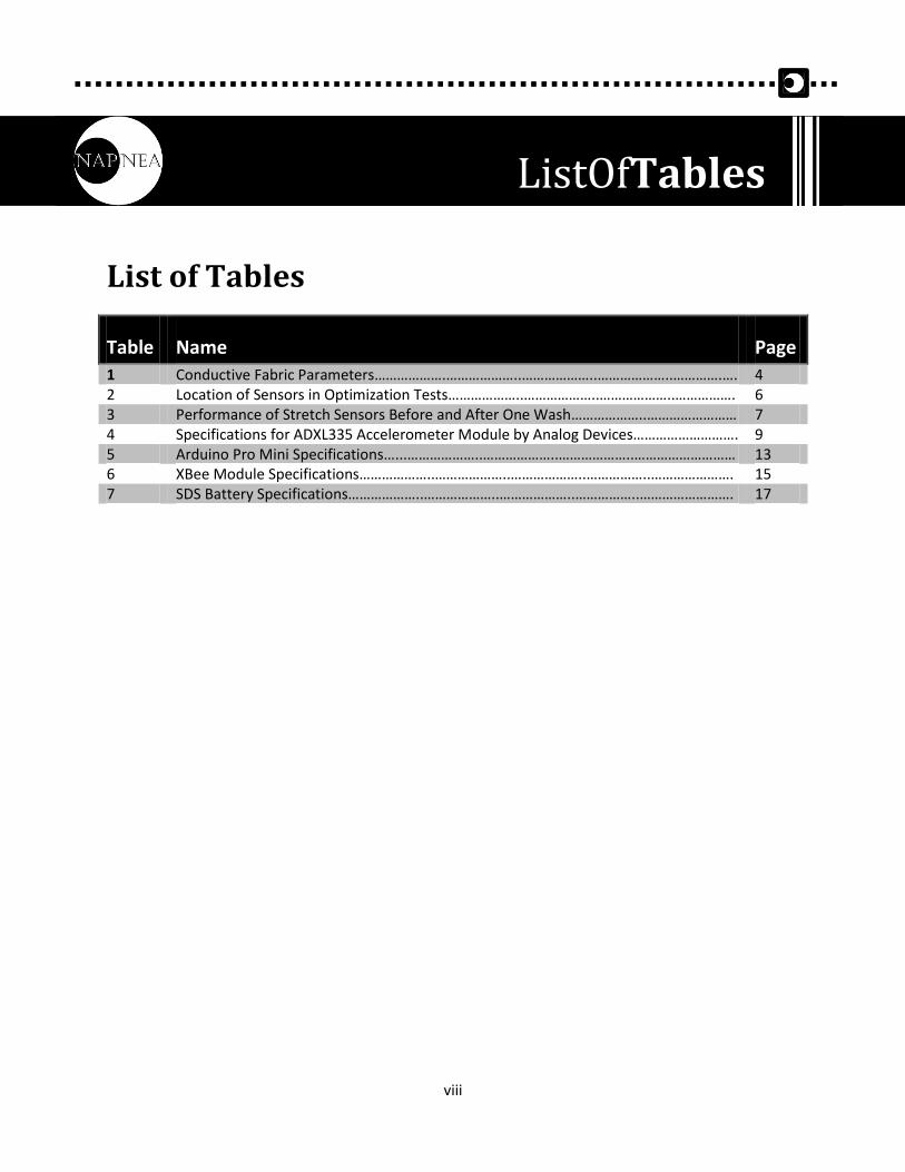
List of Tables
Table Name Page
1 Conductive Fabric Parameters……………….………………..………………..………………..………….…. 4 2 Location of Sensors in Optimization Tests………………..………………..………………..……………. 6 3 Performance of Stretch Sensors Before and After One Wash………………..…………………… 7 4 Specifications for ADXL335 Accelerometer Module by Analog Devices………………………. 9 5 Arduino Pro Mini Specifications…...………………..………………..………………..……………………… 13 6 XBee Module Specifications………………..………………..………………..……………..…………………. 15 7 SDS Battery Specifications………………..………………..………………..……………..……………………. 17
ListOfTables

ix
List of Equations
Equation Page
1 .……………….………………..………………..………………..………….…..………………..………..……… 5
2 .………………..………………..………………..……………..………………..………………..……………….. 5 3 .………………..………………………………………………………………………………………………………… 5 4 .…………………………………….………………..………………..………………..………….………………….. 8
ListOfEquations
x
Glossary
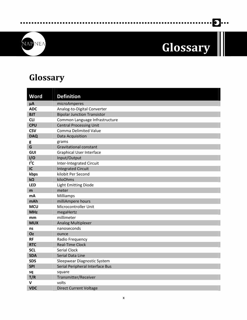
Word Definition µA microAmperes ADC Analog-to-Digital Converter BJT Bipolar Junction Transistor CLI Common Language Infrastructure CPU Central Processing Unit CSV Comma Delimited Value DAQ Data Acquisition g grams G Gravitational constant GUI Graphical User Interface I/O Input/Output I2C Inter-Integrated Circuit IC Integrated Circuit kbps kilobit Per Second kΩ kiloOhms LED Light Emitting Diode m meter mA Milliamps mAh milliAmpere hours MCU Microcontroller Unit MHz megaHertz mm millimeter MUX Analog Multiplexer ns nanoseconds Oz ounce RF Radio Frequency RTC Real-Time Clock SCL Serial Clock SDA Serial Data Line SDS Sleepwear Diagnostic System SPI Serial Peripheral Interface Bus sq square T/R Transmitter/Receiver V volts VDC Direct Current Voltage
Glossary
1
The Sleepwear Diagnostic System (SDS) is a fitted shirt embedded with various electronics and sensors
and is intended to be worn by patients during a full night’s sleep. It acquires and logs physiological data,
which includes breathing mechanics and body position. This data is analyzed by a clinician with a
custom software application that can identify sleep apnea symptoms and help diagnose patients. The
requirements for the SDS, as proposed by NAPNEA, are described in this design specification document.
1.1 Scope This design specification supports the previous Functional Specification for a Sleepwear Diagnostic
System document by outlining how the SDS functional requirements will be achieved. It also details all
technical aspects of the SDS First and Second Generation Prototypes. This includes but is not limited to
analysis of individual component performance, hardware design justification, communication protocols,
and integration of subsystems. Lastly, the document proposes a system test plan for the SDS prototypes.
1.2 Intended Audience The design specification is written for all members of NAPNEA to use as a reference throughout the
design and development process of the SDS. It will be used as a guideline to verify the feasibility of the
functional requirements and to ensure that the designs are capable of satisfying these requirements.
The design specification document also intends to justify design decisions and will be used as a template
for design modification should any problems arise during the verification testing and quality assurance
stages.
1. Introduction
2
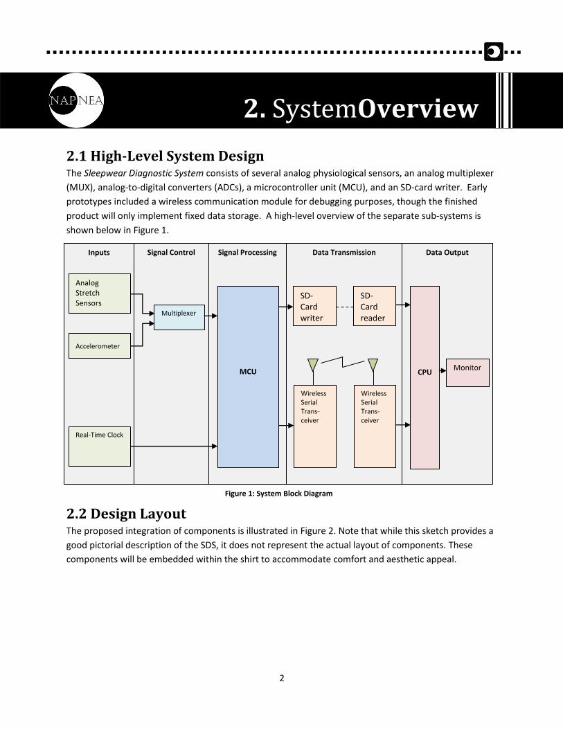
2.1 High-Level System Design The Sleepwear Diagnostic System consists of several analog physiological sensors, an analog multiplexer
(MUX), analog-to-digital converters (ADCs), a microcontroller unit (MCU), and an SD-card writer. Early
prototypes included a wireless communication module for debugging purposes, though the finished
product will only implement fixed data storage. A high-level overview of the separate sub-systems is
shown below in Figure 1.
Each sub-system (inputs, signal control, processing and data transmission) is powered through a
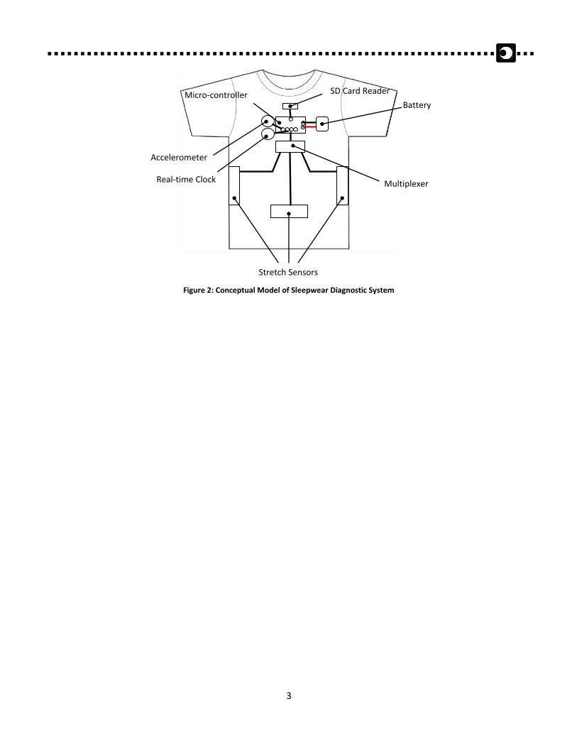
2.2 Design Layout The proposed integration of components is illustrated in Figure 2. Note that while this sketch provides a
good pictorial description of the SDS, it does not represent the actual layout of components. These
components will be embedded within the shirt to accommodate comfort and aesthetic appeal.
2. SystemOverview
Inputs
Signal Control Signal Processing Data Transmission Data Output
MCU
SD-Card writer
Analog Stretch Sensors
Accelerometer
Multiplexer
Real-Time Clock
Wireless Serial Trans-ceiver
Wireless Serial Trans-ceiver
SD-Card reader
CPU Monitor
Figure 1: System Block Diagram
3
Figure 2: Conceptual Model of Sleepwear Diagnostic System
Stretch Sensors
Accelerometer
Battery
SD Card Reader Micro-controller
Real-time Clock Multiplexer
4
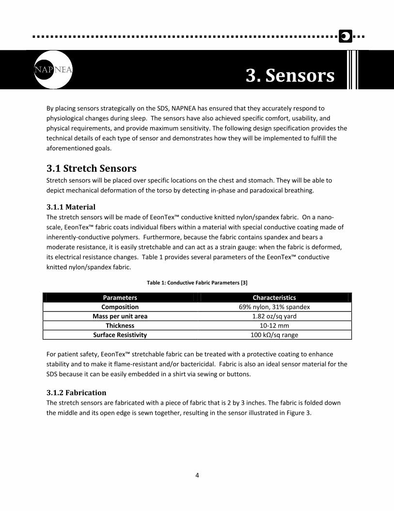
By placing sensors strategically on the SDS, NAPNEA has ensured that they accurately respond to
physiological changes during sleep. The sensors have also achieved specific comfort, usability, and
physical requirements, and provide maximum sensitivity. The following design specification provides the
technical details of each type of sensor and demonstrates how they will be implemented to fulfill the
aforementioned goals.
3.1 Stretch Sensors Stretch sensors will be placed over specific locations on the chest and stomach. They will be able to
depict mechanical deformation of the torso by detecting in-phase and paradoxical breathing.
3.1.1 Material
The stretch sensors will be made of EeonTex™ conductive knitted nylon/spandex fabric. On a nano-
scale, EeonTex™ fabric coats individual fibers within a material with special conductive coating made of
inherently-conductive polymers. Furthermore, because the fabric contains spandex and bears a
moderate resistance, it is easily stretchable and can act as a strain gauge: when the fabric is deformed,
its electrical resistance changes. Table 1 provides several parameters of the EeonTex™ conductive
knitted nylon/spandex fabric.
Table 1: Conductive Fabric Parameters [3]
Parameters Characteristics
Composition 69% nylon, 31% spandex
Mass per unit area 1.82 oz/sq yard
Thickness 10-12 mm
Surface Resistivity 100 kΩ/sq range
For patient safety, EeonTex™ stretchable fabric can be treated with a protective coating to enhance
stability and to make it flame-resistant and/or bactericidal. Fabric is also an ideal sensor material for the
SDS because it can be easily embedded in a shirt via sewing or buttons.
3.1.2 Fabrication
The stretch sensors are fabricated with a piece of fabric that is 2 by 3 inches. The fabric is folded down
the middle and its open edge is sewn together, resulting in the sensor illustrated in Figure 3.
3. Sensors
5
Figure 3: Dimensions and Sketch of Sensor
The resulting sensor has a resistivity of approximately 5 kΩ in its relaxed state and a maximum and
minimum resistivity of approximately 5.5 kΩ and 4.5 kΩ, respectively.
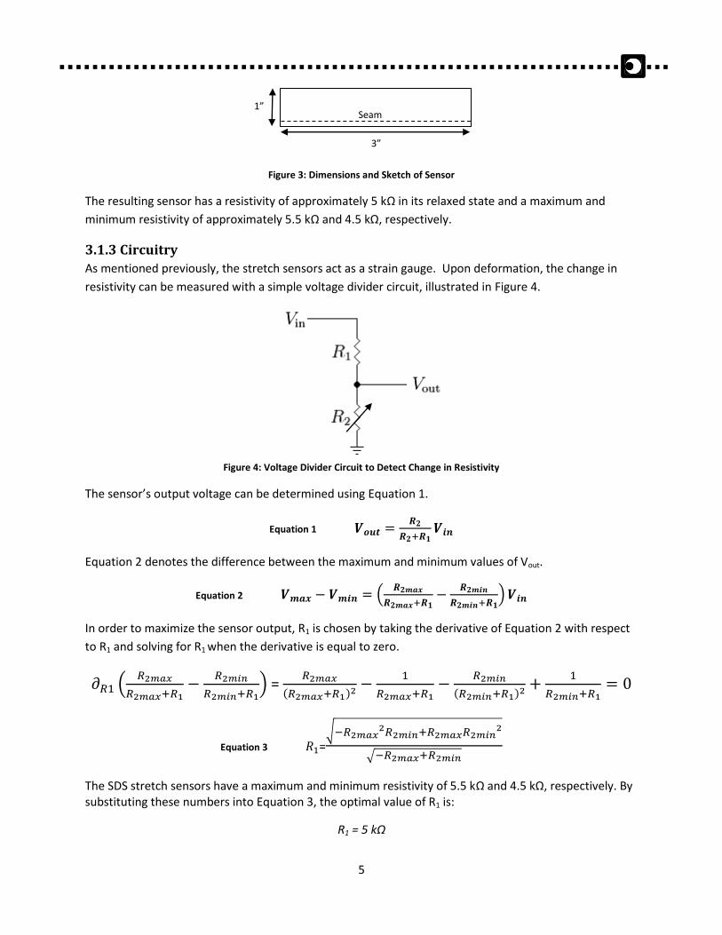
3.1.3 Circuitry
As mentioned previously, the stretch sensors act as a strain gauge. Upon deformation, the change in
resistivity can be measured with a simple voltage divider circuit, illustrated in Figure 4.
Figure 4: Voltage Divider Circuit to Detect Change in Resistivity
The sensor’s output voltage can be determined using Equation 1.
Equation 1
Equation 2 denotes the difference between the maximum and minimum values of Vout.
Equation 2 (
)
In order to maximize the sensor output, R1 is chosen by taking the derivative of Equation 2 with respect
to R1 and solving for R1 when the derivative is equal to zero.
(
) =
( )
( )
Equation 3 =√
√
The SDS stretch sensors have a maximum and minimum resistivity of 5.5 kΩ and 4.5 kΩ, respectively. By substituting these numbers into Equation 3, the optimal value of R1 is:
R1 = 5 kΩ
1”
3”
Seam
6
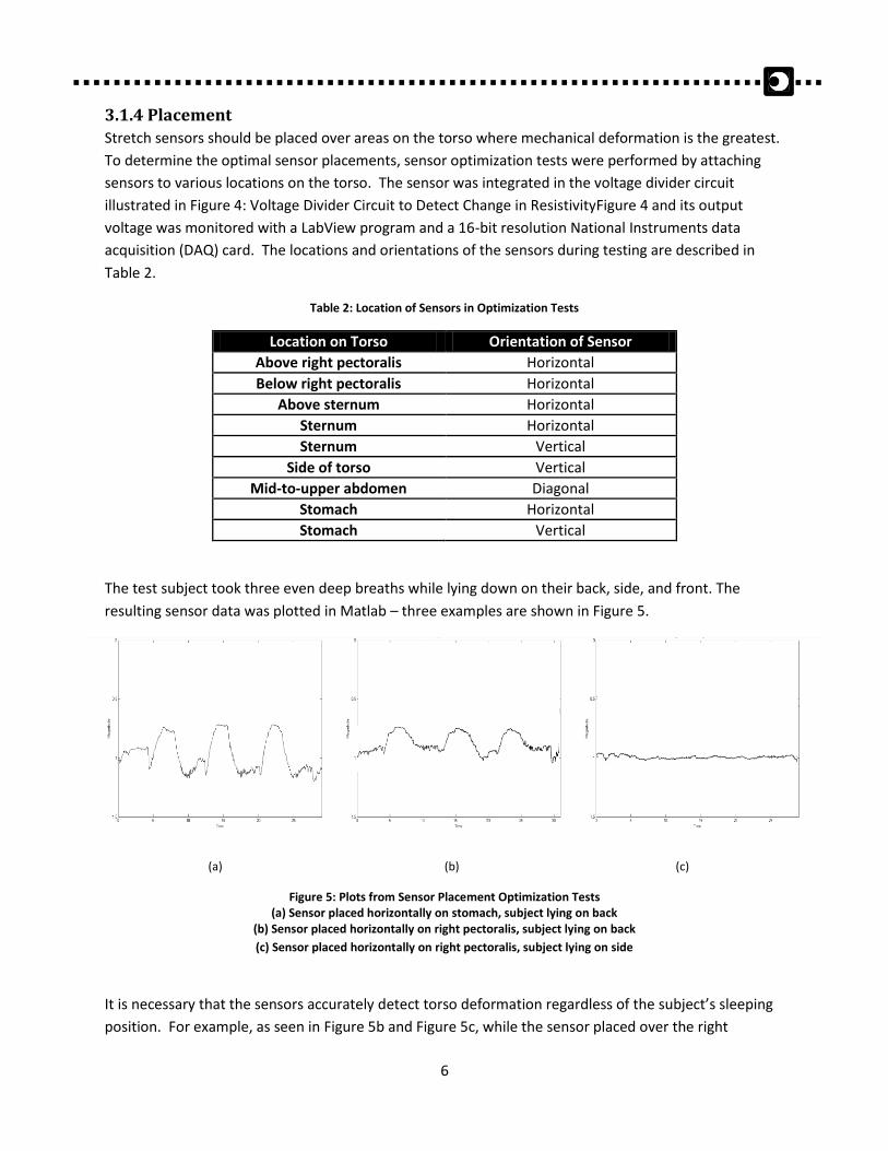
3.1.4 Placement
Stretch sensors should be placed over areas on the torso where mechanical deformation is the greatest.
To determine the optimal sensor placements, sensor optimization tests were performed by attaching
sensors to various locations on the torso. The sensor was integrated in the voltage divider circuit
illustrated in Figure 4: Voltage Divider Circuit to Detect Change in ResistivityFigure 4 and its output
voltage was monitored with a LabView program and a 16-bit resolution National Instruments data
acquisition (DAQ) card. The locations and orientations of the sensors during testing are described in
Table 2.
Table 2: Location of Sensors in Optimization Tests
Location on Torso Orientation of Sensor
Above right pectoralis Horizontal
Below right pectoralis Horizontal
Above sternum Horizontal
Sternum Horizontal
Sternum Vertical
Side of torso Vertical
Mid-to-upper abdomen Diagonal
Stomach Horizontal
Stomach Vertical
The test subject took three even deep breaths while lying down on their back, side, and front. The
resulting sensor data was plotted in Matlab – three examples are shown in Figure 5.
(a) (b) (c)
Figure 5: Plots from Sensor Placement Optimization Tests (a) Sensor placed horizontally on stomach, subject lying on back
(b) Sensor placed horizontally on right pectoralis, subject lying on back
(c) Sensor placed horizontally on right pectoralis, subject lying on side
It is necessary that the sensors accurately detect torso deformation regardless of the subject’s sleeping
position. For example, as seen in Figure 5b and Figure 5c, while the sensor placed over the right
7
pectoralis can aptly stretch while the subject is lying on their back, it cannot stretch while the subject is
sleeping on their side. Therefore, this position is not desirable.
Based on these plots, the optimal locations for sensors were determined as follows:
1. Stomach, sensor placed horizontally
2. Side, sensor placed vertically
Therefore, the SDS will contain three stretch sensors: one on each side of the torso, and one on the
stomach. The deformation of the side sensors with respect to the stomach sensor will indicate whether
the subject is breathing in-phase or paradoxically.
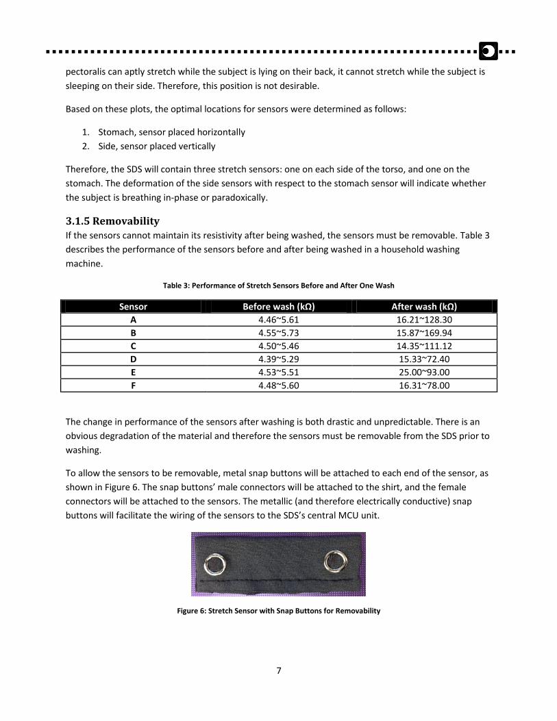
3.1.5 Removability
If the sensors cannot maintain its resistivity after being washed, the sensors must be removable. Table 3
describes the performance of the sensors before and after being washed in a household washing
machine.
Table 3: Performance of Stretch Sensors Before and After One Wash
Sensor Before wash (kΩ) After wash (kΩ)
A 4.46~5.61 16.21~128.30
B 4.55~5.73 15.87~169.94
C 4.50~5.46 14.35~111.12
D 4.39~5.29 15.33~72.40
E 4.53~5.51 25.00~93.00
F 4.48~5.60 16.31~78.00
The change in performance of the sensors after washing is both drastic and unpredictable. There is an
obvious degradation of the material and therefore the sensors must be removable from the SDS prior to
washing.
To allow the sensors to be removable, metal snap buttons will be attached to each end of the sensor, as
shown in Figure 6. The snap buttons’ male connectors will be attached to the shirt, and the female
connectors will be attached to the sensors. The metallic (and therefore electrically conductive) snap
buttons will facilitate the wiring of the sensors to the SDS’s central MCU unit.
Figure 6: Stretch Sensor with Snap Buttons for Removability
8
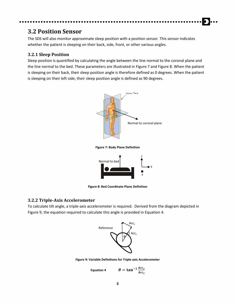
3.2 Position Sensor The SDS will also monitor approximate sleep position with a position sensor. This sensor indicates
whether the patient is sleeping on their back, side, front, or other various angles.
3.2.1 Sleep Position
Sleep position is quantified by calculating the angle between the line normal to the coronal plane and
the line normal to the bed. These parameters are illustrated in Figure 7 and Figure 8. When the patient
is sleeping on their back, their sleep position angle is therefore defined as 0 degrees. When the patient
is sleeping on their left side, their sleep position angle is defined as 90 degrees.
Figure 7: Body Plane Definition
Figure 8: Bed Coordinate Plane Definition
3.2.2 Triple-Axis Accelerometer
To calculate tilt angle, a triple-axis accelerometer is required. Derived from the diagram depicted in
Figure 9, the equation required to calculate this angle is provided in Equation 4.
Figure 9: Variable Definitions for Triple-axis Accelerometer
Equation 4
Accx
Accz
Reference
Line
θ
Normal to coronal plane
z
y
x
Normal to bed
9
The accelerometer that will be incorporated in the SDS is the ADXL335 accelerometer module from
Analog Devices. The module comes fully assembled with external components and is an extremely low-
noise, low-power consumption device. Table 4 provides several specifications of the ADXL335 module.
Table 4: Specifications for ADXL335 Accelerometer Module by Analog Devices [4]
Parameter Specification
Current draw 320 µA
Sensing range ±3 g
Operating voltage 1.8-3.7 VDC
Dimensions 4 mm x 4mm x 1.45 mm
3.3 Snore Sensor The snore sensor must be small, cost-effective, and capable of detecting snoring with minimal
interference. The following sections justify that the addition of a snore sensor to the SDS will not meet
these requirements. Likewise, a snore sensor does not coincide with the comfort, usability, and physical
requirements of the SDS. Therefore, while the possibility of integrating a snore sensor within the SDS
was fully considered, it was deemed not feasible.
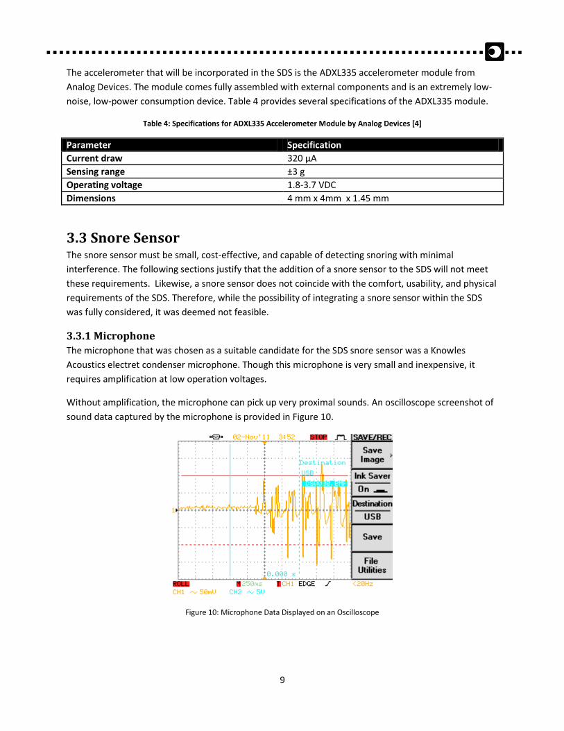
3.3.1 Microphone
The microphone that was chosen as a suitable candidate for the SDS snore sensor was a Knowles
Acoustics electret condenser microphone. Though this microphone is very small and inexpensive, it
requires amplification at low operation voltages.
Without amplification, the microphone can pick up very proximal sounds. An oscilloscope screenshot of
sound data captured by the microphone is provided in Figure 10.
Figure 10: Microphone Data Displayed on an Oscilloscope
10
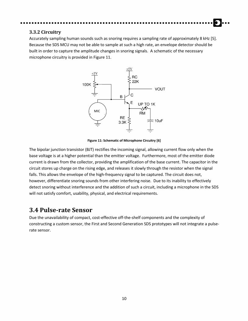
3.3.2 Circuitry
Accurately sampling human sounds such as snoring requires a sampling rate of approximately 8 kHz [5].
Because the SDS MCU may not be able to sample at such a high rate, an envelope detector should be
built in order to capture the amplitude changes in snoring signals. A schematic of the necessary
microphone circuitry is provided in Figure 11.
Figure 11: Schematic of Microphone Circuitry [6]
The bipolar junction transistor (BJT) rectifies the incoming signal, allowing current flow only when the
base voltage is at a higher potential than the emitter voltage. Furthermore, most of the emitter diode
current is drawn from the collector, providing the amplification of the base current. The capacitor in the
circuit stores up charge on the rising edge, and releases it slowly through the resistor when the signal
falls. This allows the envelope of the high-frequency signal to be captured. The circuit does not,
however, differentiate snoring sounds from other interfering noise. Due to its inability to effectively
detect snoring without interference and the addition of such a circuit, including a microphone in the SDS
will not satisfy comfort, usability, physical, and electrical requirements.
3.4 Pulse-rate Sensor Due the unavailability of compact, cost-effective off-the-shelf components and the complexity of
constructing a custom sensor, the First and Second Generation SDS prototypes will not integrate a pulse-
rate sensor.
MIC
11
Designing their system with the user in mind, the SDS’s Sleepwear Shirt provides the patient the
familiarity of using everyday clothing as well as the convenience and security of staying in their own
home as part of the data-collection procedure. Moreover, the Sleepwear Shirt ensures that all encased
circuitry does not move around and disturb or ruin the data collection, unlike other take-home devices
where any shift in the recording belts around a patient’s torso results in inaccurate and unusable data.
NAPNEA also chose a shirt that would ensure comfortability, breathability to reduce sweat and easy
washability. Lastly, each prototype created was made to suit a different body type. This demonstrates
the SDS’s catering to both men and women. The following design specification provides the technical
details of the Sleepwear shirt and demonstrates how they will be implemented to fulfill the
aforementioned goals.
4.1 Material The shirt material is made to achieve four aspects above all else: breathability, a compression fit and
stretch ability/durability.
4.1.1 Breathability
Breathable shirt material ensures that any perspiration or moisture is avoided to help keep the patient
light, dry and cool throughout the night. This is done by moving sweat away from the skin to the fabric's
surface, where it quickly evaporates. Such a process safeguards the data collection against any
interference from humidity present.
4.1.2 Compression Fit
A close compression fit to the body is similar to wearing a second skin, a significant factor in accurate
data collection, as the stretch sensors along with the shirt material will faithfully replicate the patient’s
movements. However, the fit is not restricting to the patient’s motions.
4.1.3 Stretch Ability/ Durability
The Sleepwear Shirt material is able to stretch in all directions for an enhanced range of motion without
causing wear and tear of the fabric after numerous uses. With the feature of washability, this shirt
minimalizes disposability and ensures a long product life.
4.2 Electronics Embedding The SDS electronics must be invisible to the patient and embedded within the shirt such that the
patient’s comfort is not negatively affected.
4. SleepwearShirt
12
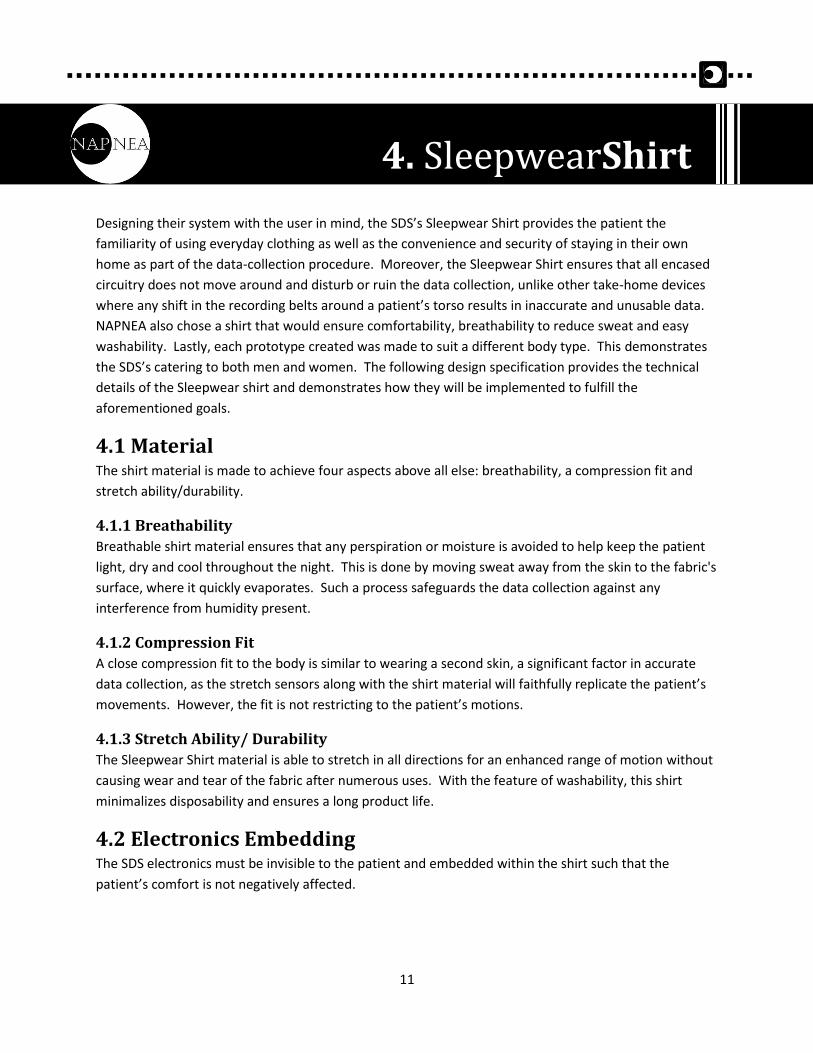
4.2.1 Lining
All wires are held in place between the shirt and an additional piece of material referred to as the
“lining”. The lining separates the electronics from the patient’s skin so that there is no interference from
the body’s capacitance and to ensure patient safety. Figure 12 illustrates the placement and shape of
the lining. To enhance aesthetics, the lining is sewn to the inside of the shirt and is not visible when the
patient is wearing it. The dotted lines represent wires, which are placed between the lining and the shirt
and connect the stretch sensors to the hardware module.
Figure 12: Sleepwear Shirt with Lining.
The lining is made of a stretchy knit fabric, sewed to synchronize the movement of the shirt itself as the
patient sleeps.
4.2.2 Pocket
A removable hardware module (discussed in section 5) is placed inside a pocket within the lining. The
pocket’s dimensions match the module’s dimensions so that the module cannot shift during sleep. This
is important because the accelerometer must always be oriented correctly in order to gather accurate
body position information. Additionally, the hardware module is sealed in a clear plastic pouch for easy
removability for washing. This also prevents pieces from breaking off and getting lost. Affordances have
been thoughtfully included in the design so that the patient cannot set up the hardware incorrectly.
4.2.2 Sewing
Flat seams are used to eliminate distracting irritation from chafing or irritation. In order to keep
components static during restless sleep activity, all electrical wires have been sewn into place. As
mentioned in 3.1.5, snap buttons are used to allow sensors to be removable. Because they are
electrically conductive, snap buttons will facilitate the wiring of the sensors to the SDS’s central MCU
unit.
Lining
13
The SDS hardware is embedded within the Sleepwear Shirt and must be designed to provide optimal
comfort without compromising functionality. The hardware consists of the device’s central processing
unit (the MCU), a real-time clock (RTC), a SD card reader to log data or a wireless transmitter to transfer
data directly to a computer processing unit (CPU) in real-time, and any other digital or analog
components to facilitate data collection and/or transmission.
5.1 Microcontroller The SDS hardware should not interfere with patients’ regular sleeping habits. Therefore, it must be fairly
compact and light-weight such that the patient cannot feel any discomfort when the SDS is worn. In
order to satisfy this requirement, the MCU that was selected is the Arduino Pro Mini based on
the ATmega328. The specifications for this MCU are provided in Table 5.
Table 5: Arduino Pro Mini Specifications [6]
Parameter Characteristics
Dimensions 18 mm x 33 mm x 1.5 mm
Weight < 2g
Operating voltage 3.3V
Resolution 10-bit
Clock speed 8MHz
Digital input/output (I/O) pins 12
Analog input pins 6
Because the SDS sensors can operate under 3.3V, they can be powered directly by the MCU. However, in
order to avoid crosstalk, each sensor should be powered by a separate source. The MCU digital pins will
be used as power sources and sinks. When set to digital HIGH, these pins provide 3.3V. When set to
digital LOW, these pins act as a ground. Therefore, because there are four sensors, eight digital I/O pins
will be designated for sensor powering.
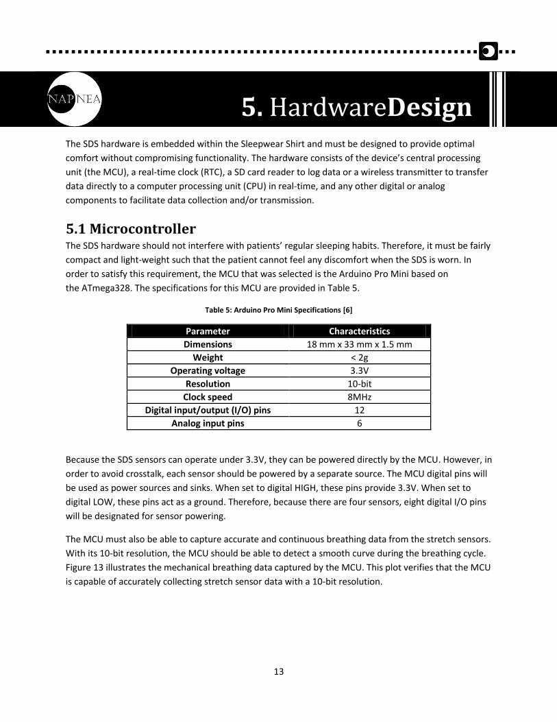
The MCU must also be able to capture accurate and continuous breathing data from the stretch sensors.
With its 10-bit resolution, the MCU should be able to detect a smooth curve during the breathing cycle.
Figure 13 illustrates the mechanical breathing data captured by the MCU. This plot verifies that the MCU
is capable of accurately collecting stretch sensor data with a 10-bit resolution.
5. HardwareDesign
14
Figure 13: Stretch Sensor Data Collected by MCU
The Arduino Pro Mini does not have enough analog and digital pins to accommodate all the hardware
components and sensors. Since eight analog pins are required, an MUX will be used to rapidly and
sequentially provide data to the MCU while only requiring one analog pin. Since sixteen digital pins are
required, a second Arduino Pro Mini will be used; one Arduino will provide power sources and grounds
for the sensors, and the second Arduino will contain all the data processing and embedded software of
the SDS.
5.2 Multiplexer A 16-channel MUX will be used to relay data from three different stretch sensors to the MCU. Although
this component has more channels than needed, it was chosen because it is inexpensive, compact (40
mm x 18 mm x 1.5 mm), readily available, and conveniently came with a breakout board. It also allows
for additional components to be integrated with the SDS, should alterations be made to future-
generation prototypes.
The MUX is interfaced with the MCU in the following way: four digital pins provide the MUX with four
address bits, and one analog pin receives data from the MUX’s output. The MUX has a minute 22ns
propagation delay [8], and can therefore provide data to the MCU whilst preserving real-time integrity.
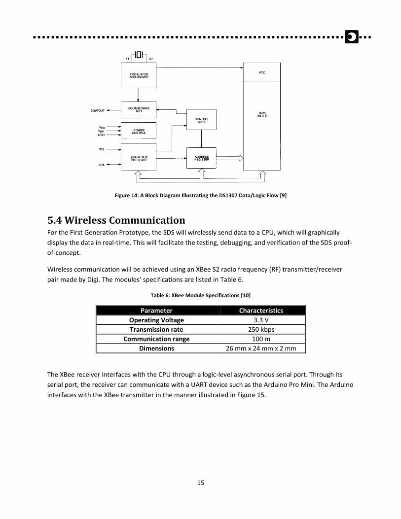
5.3 Real-time Clock A DS1307 RTC module will be used to keep track of time and will allow clinicians to precisely monitor
when and for how long apneaic events occur. The module is compact (20 mm x 20 mm x 10 mm) and
comes with an external lithium coin cell battery that can run the RTC for a minimum of nine years [9]. It
consists of an RTC integrated circuit (IC) and a crystal oscillator, and can be accessed via inter-integrated
circuit (I2C) protocol. I²C uses only two bidirectional open-drain lines: Serial Data Line (SDA) and Serial
Clock (SCL). The Arduino Pro Mini supports I2C communication and has two analog pins designated for
SDA and SCL lines. Figure 14 provides a block diagram of the DS1307’s data flow.
Am
plit
ud
e
Time (s)
Side Sensor
StomachSensor
15
Figure 14: A Block Diagram Illustrating the DS1307 Data/Logic Flow [9]
5.4 Wireless Communication For the First Generation Prototype, the SDS will wirelessly send data to a CPU, which will graphically
display the data in real-time. This will facilitate the testing, debugging, and verification of the SDS proof-
of-concept.
Wireless communication will be achieved using an XBee S2 radio frequency (RF) transmitter/receiver
pair made by Digi. The modules’ specifications are listed in Table 6.
Table 6: XBee Module Specifications [10]
Parameter Characteristics
Operating Voltage 3.3 V
Transmission rate 250 kbps
Communication range 100 m
Dimensions 26 mm x 24 mm x 2 mm
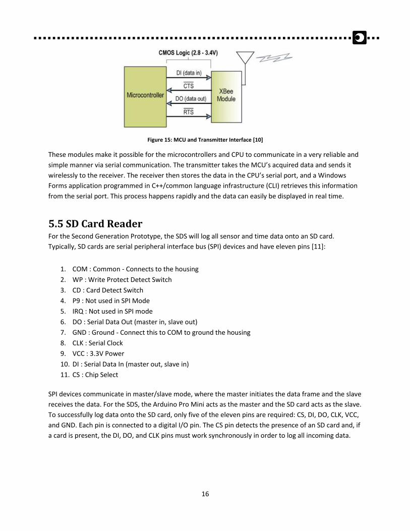
The XBee receiver interfaces with the CPU through a logic-level asynchronous serial port. Through its
serial port, the receiver can communicate with a UART device such as the Arduino Pro Mini. The Arduino
interfaces with the XBee transmitter in the manner illustrated in Figure 15.
16
Figure 15: MCU and Transmitter Interface [10]
These modules make it possible for the microcontrollers and CPU to communicate in a very reliable and
simple manner via serial communication. The transmitter takes the MCU’s acquired data and sends it
wirelessly to the receiver. The receiver then stores the data in the CPU’s serial port, and a Windows
Forms application programmed in C++/common language infrastructure (CLI) retrieves this information
from the serial port. This process happens rapidly and the data can easily be displayed in real time.
5.5 SD Card Reader For the Second Generation Prototype, the SDS will log all sensor and time data onto an SD card.
Typically, SD cards are serial peripheral interface bus (SPI) devices and have eleven pins [11]:
1. COM : Common - Connects to the housing
2. WP : Write Protect Detect Switch
3. CD : Card Detect Switch
4. P9 : Not used in SPI Mode
5. IRQ : Not used in SPI mode
6. DO : Serial Data Out (master in, slave out)
7. GND : Ground - Connect this to COM to ground the housing
8. CLK : Serial Clock
9. VCC : 3.3V Power
10. DI : Serial Data In (master out, slave in)
11. CS : Chip Select
SPI devices communicate in master/slave mode, where the master initiates the data frame and the slave
receives the data. For the SDS, the Arduino Pro Mini acts as the master and the SD card acts as the slave.
To successfully log data onto the SD card, only five of the eleven pins are required: CS, DI, DO, CLK, VCC,
and GND. Each pin is connected to a digital I/O pin. The CS pin detects the presence of an SD card and, if
a card is present, the DI, DO, and CLK pins must work synchronously in order to log all incoming data.
17
5.6 Battery All electronic components of the SDS were chosen such that the entire device could be powered by a
single low-voltage battery. The SDS battery will be a polymer lithium ion battery, whose specifications
are listed in Table 7.
Table 7: SDS Battery Specifications [12]
Parameter Characteristics
Nominal voltage 3.7 V
Nominal capacity 2000 mAh
Maximum discharge current 2.0 A
Weight 37 g
Dimensions 54 mm x 54 mm x 5.8 mm
When all hardware components are integrated, the Second Generation SDS has a current draw of
approximately 8.5 mA. The battery can therefore sufficiently power the SDS, and also has built-in
protection against over-voltage and over-current. This battery was chosen over the lighter, 850 mAh
battery because of its lifespan.
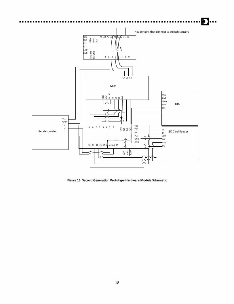
5.7 Complete Hardware Module With all components integrated, the final hardware module for the Second Generation Prototype,
illustrated in Figure 16, is 60 mm x 85 mm and approximately 55 g. The battery powers the module via
the “RAW” and “GND” pins of each MCU. A small slider switch turns the module on and off and LEDs on
each MCU light up when the module is on.
The module is easily removable from the SDS. As seen at the top of Figure 16, there are six “header pins
that connect to stretch sensors.” These male header pins plug in to a six-socket female molex connector
on the sleepwear shirt. The female connector is attached to the stretch sensors’ wires and are fully
washable and therefore not detachable from the shirt.
18
Figure 16: Second Generation Prototype Hardware Module Schematic
9 8 7 6 5 4 3 2
GN
D
RST
RX
I
TXO
TXO
TXO
RXI
VCC
GND
GND
10 11 12 13 A0 A1 A2 A4 A5
VC
C
GN
D
RA
W
Accelerometer
VCC
GND
x
y
z
RTC
VCC
GND
SWQ
SDA
SCL
SD Card Reader CS
DI
VCC
CLK
GND
DO
2 3 4 5 6 7 8 9
TXO
RX
T
RSI
GN
D
TXO
TXO
RXI
VCC
GND
GND
A5 A4 A2 A1 A0 13 12 11 10
RA
W
GN
D
VC
C
GN
D
VC
C
EN
S0
S1
S2
S3
SIG
MUX
C7 C8 C9
Header pins that connect to stretch sensors
19
The embedded software programmed in the MCU coordinates all electronic components to ensure that
physiological breathing data is accurately collected in cooperation with the RTC and logged correctly
onto the SD card. The following sections describe how the device’s embedded software concludes the
functionality of the SDS.
6.1 Setup Every time the hardware module is reset (i.e. toggled from its off state to its on state), the embedded
software must initialize the system to ensure that each iteration can be performed properly. System
initialization includes the following:
1. Wireless communication or data logging setup
a. First Generation: check if CPU COM port is present and receiver is listening
i. if not present, exit
b. Second Generation: check if SD card is present
i. if present, create an empty comma delimited value text file (“.csv”) for SD card
to write to
ii. if not present, exit
2. Set power sources (digital pins powering the sensors)
3. Set baud rate to 9600 bits per second
After these elements are initialized, the embedded software will perform appropriately.
6.2 Iterations The SDS provides four key pieces of information:
1. Movement of the chest during breathing
2. Movement of the stomach during breathing
3. Body position throughout the night
4. Time of events (Second Generation Prototype only)
Firstly, the MCU must sequentially gather this information at a rate such that important data is not lost.
Thus, the MCU must ideally execute each iteration of code at least ten times per second. For each
iteration, the MCU must gather all sensor data, sync it with the time data, and send it wirelessly to the
CPU (First Generation) or log this information onto the SD card (Second Generation). The sequence of
events is as described in the pseudo code provided in Figure 17.
6. EmbeddedSoftware
20
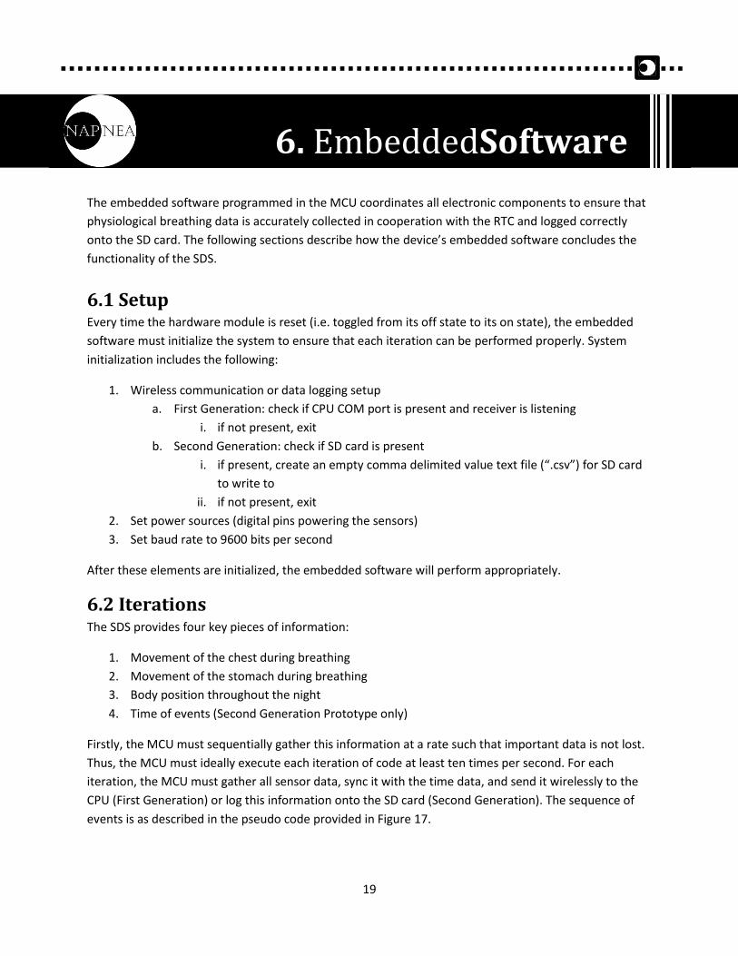
//Gather data from the MUX by changing the 4-bit address and reading the MUX output data //Address is changed by switching the digital address pins to high or low, according to the truth table MUX(address 1); sideSensor1 = MUX(output); MUX(address 2); sideSensor2 = MUX(output); MUX(address 3); stomachSensor = MUX(output); //Gather data from the accelerometer and convert it to tilt angle information angle = arctan(Acc_X, Acc_Z)*180/PI; //Send data wirelessly via serial communication **First Gen only** Serial.print(sideSensor1,sideSensor2,stomachSensor,angle); //Gather data from the real-time clock **Second Gen only** hour = clock.hour(); minute = clock.minute(); second = clock.second(); //Log data onto SD Card in this specific format: //sideSensor1,sideSensor2,stomachSensor,angle,hour:minute:second **Second Gen only** SDCard.write(sideSensor1); SDCard.write(“,”); SDCard.write(sideSensor2); SDCard.write(“,”); SDCard.write(stomachSensor); SDCard.write(“,”); SDCard.write(angle); SDCard.write(“,”); SDCard.write(hour); SDCard.write(“:”); SDCard.write(minute); SDCard.write(“:”); SDCard.write(second); //line break here
Figure 17: Pseudo Code to Describe a Single Iteration
One iteration saves one complete line of data onto the SD card. An average of 18 iterations can be
performed per second.
21
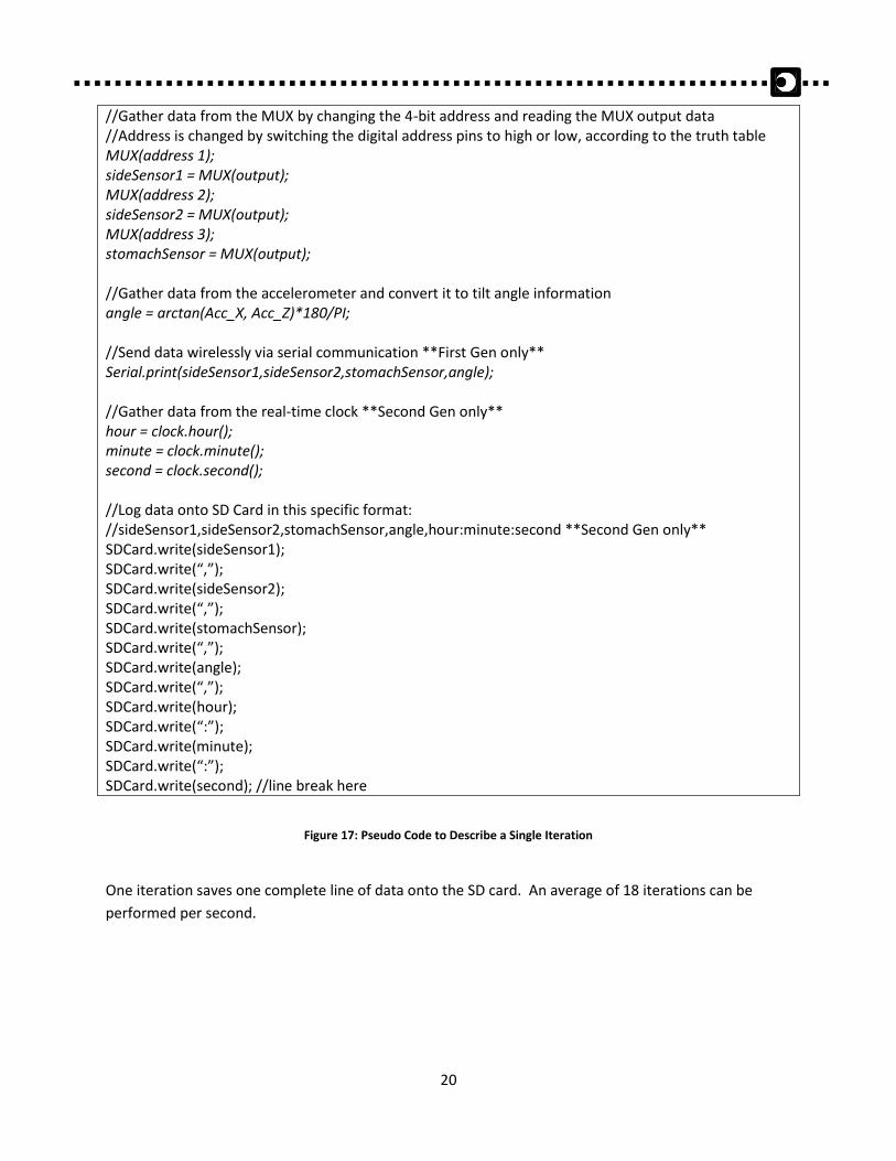
6.3 Summary The flowchart in Figure 18 summarizes how the embedded software works.
Figure 18: Embedded Software Flowchart
Start
SD card/COM port
present?
yes
Initialize hardware
Change MUX address and
record sensor data
Is MUX cycle complete?
yes
no
Record Accelerometer data
and convert to angle
Record hour, minute,
second data from RTC
Save to SD card
no
Exit
22
After the sensor data is logged by the MCU, it is either transmitted wirelessly via the XBee transceiver
(First Generation) or stored onto an SD card (Second Generation). This data will then be acquired by the
software design portion of the SDS. After receiving the data onto a compatible CPU (PC or Mac), the
software program will access this collected data and perform analyses. The software program is
designed to be user friendly, with intuitive graphical user interfaces, and provide easy-to-understand
visual feedback in the form of graphs with legends, pictures, and notifications buttons.
A separate software program is designed to work on a mobile phone, further improving the simplicity
and convenience of the SDS. The phone application will provide similar functionality as the CPU
application, with the additional benefit that the data can be accessed and processed at any time, where
internet connection is available.
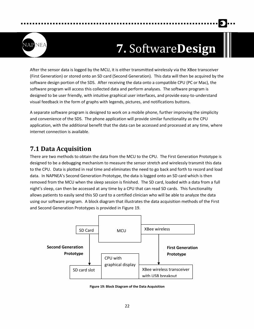
7.1 Data Acquisition There are two methods to obtain the data from the MCU to the CPU. The First Generation Prototype is
designed to be a debugging mechanism to measure the sensor stretch and wirelessly transmit this data
to the CPU. Data is plotted in real time and eliminates the need to go back and forth to record and load
data. In NAPNEA’s Second Generation Prototype, the data is logged onto an SD card which is then
removed from the MCU when the sleep session is finished. The SD card, loaded with a data from a full
night’s sleep, can then be accessed at any time by a CPU that can read SD cards. This functionality
allows patients to easily send this SD card to a certified clinician who will be able to analyze the data
using our software program. A block diagram that illustrates the data acquisition methods of the First
and Second Generation Prototypes is provided in Figure 19.
Figure 19: Block Diagram of the Data Acquisition
SD Card XBee wireless
transceiver
MCU
XBee wireless transceiver
with USB breakout
SD card slot
CPU with
graphical display
Prototype 1 Prototype 2
7. SoftwareDesign
Second Generation
Prototype
First Generation
Prototype
23
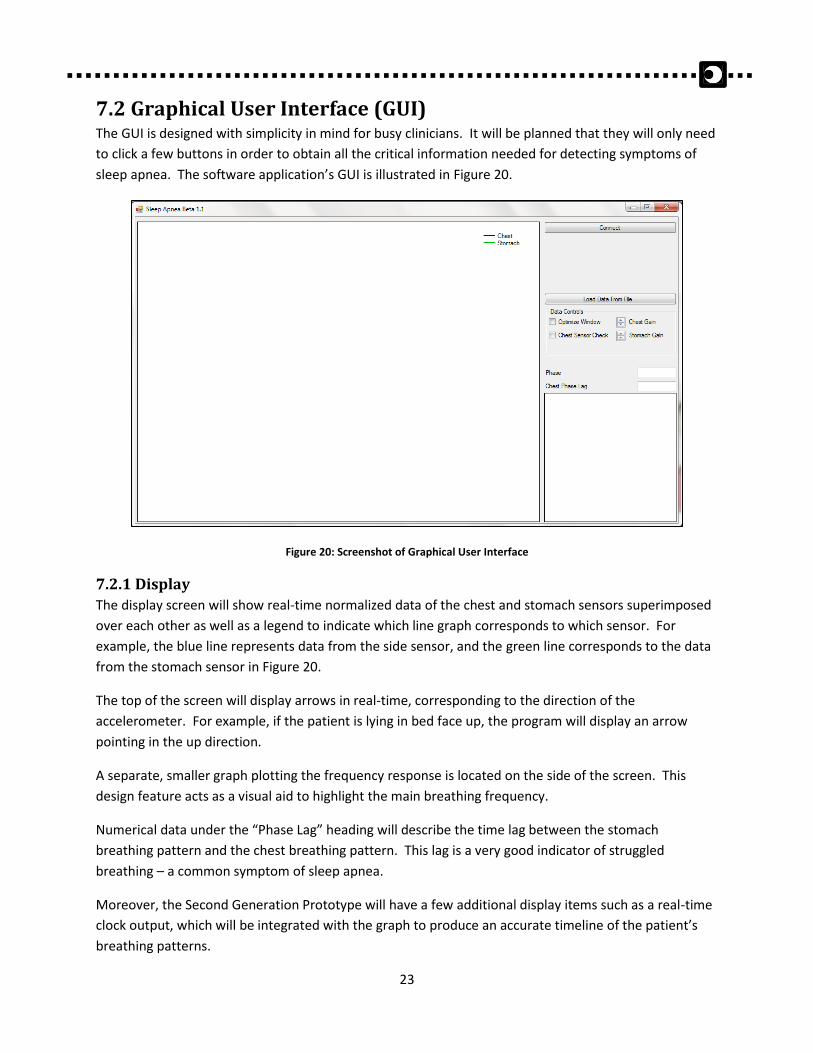
7.2 Graphical User Interface (GUI) The GUI is designed with simplicity in mind for busy clinicians. It will be planned that they will only need
to click a few buttons in order to obtain all the critical information needed for detecting symptoms of
sleep apnea. The software application’s GUI is illustrated in Figure 20.
Figure 20: Screenshot of Graphical User Interface
7.2.1 Display
The display screen will show real-time normalized data of the chest and stomach sensors superimposed
over each other as well as a legend to indicate which line graph corresponds to which sensor. For
example, the blue line represents data from the side sensor, and the green line corresponds to the data
from the stomach sensor in Figure 20.
The top of the screen will display arrows in real-time, corresponding to the direction of the
accelerometer. For example, if the patient is lying in bed face up, the program will display an arrow
pointing in the up direction.
A separate, smaller graph plotting the frequency response is located on the side of the screen. This
design feature acts as a visual aid to highlight the main breathing frequency.
Numerical data under the “Phase Lag” heading will describe the time lag between the stomach
breathing pattern and the chest breathing pattern. This lag is a very good indicator of struggled
breathing – a common symptom of sleep apnea.
Moreover, the Second Generation Prototype will have a few additional display items such as a real-time
clock output, which will be integrated with the graph to produce an accurate timeline of the patient’s
breathing patterns.
24
7.2.2 Buttons
Adjacent to the display screen will be buttons to control the analysis of the data. The “Connect” button
(for the First Generation Prototype) searches for the COM port that the wireless XBee transceiver is
connected to. Activating the connect button sends a command to all COM ports and waits for a
response. Once the active COM port has responded, the data is transmitted wirelessly to the program
where it begins to plot.
In the Second Generation Prototype, the “Load” button opens a prompt that asks the user to locate the
data on the SD card. Similar to the First Generation Prototype, once the data is found and loaded, the
data is ready to be plotted and analyzed.
7.3 Phone Application A website will be created to allow the general public to find out more information about NAPNEA and
the Sleepwear Diagnostic System. The design of this website will be modern and simplistic, aimed at
user-friendliness. There will be one menu on the left sidebar where the user can navigate toward
different sections of the website.
This website will be created using Adobe Dreamweaver CS5.5, using html coding in conjunction with
website making templates. The site will be hosted on the Simon Fraser University server, under the URL
www.sfu.ca/~jkc10. Various sections such as “About NAPNEA” and “Company Profiles” will provide
information to investors or potential customers, whereas the section under “SDS Analysis” will open up
a page that resembles the CPU program to analyze sleep data.
Data that is previously uploaded to the server can be accessed by the patient or clinician using assigned
login credentials. Once the user has logged in, they will be able to view the plotted data on the website.
This application is designed to run on a website so that the general public can learn about NAPNEA and
sleep apnea and potential customers and investors can learn about how the SDS works. Also, a patient
or clinician can access their data easily. Using any mobile device with access to the internet and with
the proper credentials, a user can login and view the results of a sleep experiment.
25
The field of medical diagnostic systems is one of high importance as people depend on it for their well-
being. This is why it is crucial for any system that will be used on a patient to be fully functioning as
intended and have a high accuracy of results. To ensure that patients using our system will be at ease in
knowing they are receiving the best diagnosis for their sleep activity, a rigorous test plan will be
followed. The system test plan will consist of five in-depth testing stages, first making sure the separate
modules function properly on their own and then together as a final unit. The five testing stages will be
categorized and divided up into individual component testing, sensor optimization, integrated unit
testing, qualitative testing and software testing.
8.1 Individual Component Testing There are many different components that make up our system. Each component must be able to fully
perform their basic functions without error before they can be integrated into our system.
8.1.1 MCU
Purpose: Able to store and run a program
Procedure: Write a basic program capable of testing all fundamental functions
Expected Result: The MCU successfully outputs the expected results of the program
8.1.2 Accelerometer
Purpose: Able to detect acceleration in three dimensions with negligible error
Procedure: Orientate the electronic component at fixed inclinations (0°, 90°, 180°, etc)
Expected Result: The resulting data is accurate to ±0.1°
8.1.3 Real-time Clock
Purpose: Able to maintain time information with its own external power supply
Procedure: Write a simple Arduino code to initialize the clock and verify after a period of 72
hours that the time held by the clock is still correct
Expected Result: The clock will maintain time information properly over the time period
8.1.4 XBee module
Purpose: Ensure that a continuous wireless connection can be held between the MCU and CPU
via XBee T/R modules
Procedure: Connect one XBee module to the MCU and the other to the CPU and send data from
the MCU to the CPU using the XBee modules
Expected Result: The CPU will recognize the MCU in a serial COM port and receive transmitted
data in real time without data loss
8. SystemTestPlan
26
8.1.5 Stretch Sensor
Purpose 1: Able to accurately detect physical deformation with a 10-bit resolution MCU
Procedure: Connect the MCU to a stretch sensor and plot the resulting stretch deformation
output (i.e. change in output voltage)
Expected Result: The MCU’s resolution is still high enough to produce precise results
Purpose 2: Determine the best sensor location available for data collection
Procedure: Place sensors on various sections of the chest and abdomen and plot resulting
breathing deformation
Expected Result: The best location is selected based on which sensor outputs the greatest
change in voltage and movement fidelity
8.1.6 Battery
Purpose: Approximate battery life for powering the MCU
Procedure: Power the MCU with the battery and allow it to run until no longer able to provide
3.3V to the MCU
Expected Result: The battery should power the system for at least 24 hours
8.2 First Generation Prototype Testing The First Generation Prototype, a proof-of-concept shirt, requires the capability to wirelessly transmit
data collected from the stretch and position sensors to the CPU and display it in real-time for debugging
and analysis purposes.
Once all of the individual components have been tested thoroughly and integrated into the SDS, the
total system will undergo functionality testing as a whole. This will be done through a subject wearing
the shirt while lying down to simulate typical sleeping scenarios. The subject will change sleeping
position (lying on their back, both sides and front) when breathing normally and when simulating apneic
events. All of the data will be viewed from the software in real-time to see if each sensor is behaving
optimally and as expected.
The results of the First Generation Prototype testing are a crucial part of the development of the SDS as
it will indicate whether adjustments to sensor placement or the sensors themselves are necessary to
move forward.
8.3 Second Generation Prototype Testing After the Second Generation Prototype is fabricated, using the results of the First Generation Prototype,
functionality testing of the Second Generation Prototype will commence. The main goal of testing the
Second Generation Prototype will be to determine if a full night’s worth of data can be accurately and
reliably collected. Any sensor placement and other sensor issues will have been solved by now so there
will be no need for real-time debugging except for the snore sensor. A SD-card will be used to store all of
27
the collected data onto a memory device which will later be analyzed with the accompanying custom
software programs.
To test for over-night data collection, subjects will put on the shirt and turn it on before their normal
night’s worth of sleep. The data will later be analyzed to confirm that all sensors performed correctly
throughout the night without any glitches.
The resulting data should show that the sensors did not shift during the night nor did the shirt turn off at
any point. It is also important that the data is accurately synchronized with time (day, hour, second) and
that the real-time clock accurately outputs this information.
8.4 Qualitative Testing While the data must be tested for accuracy, its collection process must be tested for ease-of-setup (from
a user’s standpoint). The following sections outline how these two design aspects will be tested for.
8.4.1 Usability
Once the Second Generation Prototype is finished, subjects uninvolved in the design process will test
the SDS for a full night’s sleep of data collection. They will be asked to rate the system on patient setup,
intuitiveness of the system, comfort of the Sleepwear Shirt, and overall ease-of-use. This will offer
NAPNEA a better understanding of the SDS’s usability and operation.
8.5 Software Testing Once testing has proven that all components are individually operating as they should, these
components combined as a unit, together with the software, will undergo testing.
8.5.1 Usability
Throughout the software design process, the user interface will be kept straightforward and concise, as
NAPNEA keeps the user in mind. Initial software testing will be performed by the members of NAPNEA
as the software gets built. Once a version of the software that is close to the end-product is available,
subjects uninvolved in the software design process – friends, family and Dr. Najib Ayas – will be asked to
evaluate the programs for its instinctiveness. They will also be asked to highlight issues that may have
been overlooked by the creators.
The main goal of the software will be an interactive and clear program that requires minimal training.
Buttons, menus and displays as well as functions such as saving, loading and viewing the data will be
tested for user-friendliness. Moreover, users should be able to scroll through, enlarge and zoom into
and out of graphs.
8.5.2 Algorithm
The algorithm will be tested for its ability and accuracy to zone in on apneic events based on sensor
data. Testing will also ensure that the program will display breathing phase data and sleep position
correctly. Likewise, day and time of data collection (accurate to the second) also should show properly.

28
8.6 Future Testing Due to the scope and timeline of our project, NAPNEA will be unable to perform clinical trials. Future
testing involves clinical trials where both sleep apneaic patients and a non- sleep apneaic control group
wear the Sleepwear Shirt during data collection. Results from these trials will be compared to current
sleep analysis devices.
29
Through a meticulous and well-planned design process, NAPNEA has been able to successfully realize
their goals and create a device that complies with a specific set of functional requirements. The
engineers of NAPNEA, equipped with technical know-how and a comprehensive functional specification
document, have produced a detailed design specification document that will serve as a reference for
product manufacturing and future-generation prototypes. It justifies design choices and reveals the
thoughtfulness that went into creating an innovative and clinically-relevant device that can greatly
impact the healthcare industry.
NAPNEA is excited to produce and demonstrate the Sleepwear Diagnostic System to sleep clinic
technicians, clinicians, and researchers as a device that may one day become the golden standard for
sleep apnea diagnosis.
Conclusion
30
[1] Public Health Agency of Canada. (2010, Dec 10). What is the Impact of Sleep Apnea on Canadians.
[Online]. Available: http://www.phac-aspc.gc.ca/cd-mc/sleepapnea-apneesommeil/ff-rr-2009-
eng.php [Accessed: 2011, Sep 20].
[2] Sleep Apnea Surgery, Diagnosis Test and Sleep Apnea Treatment. (2011). How Common is Sleep
Apnea? [Online]. Available: http://www.sleepapnea-source.com/how-common-is-sleep-apnea/
[Accessed: 2011, Nov 6 20].
[3] Eeonyx CORPORATION. (2009). EEONTEX™ CONDUCTIVE STRETCHABLE FABRIC. [Online]. Available:
http://www.eeonyx.com/pdf/EeonTex/EtexStretchLRslpa10e5.pdf [Accessed: 2011, Nov. 11].
[4] Analog Devices. (2009). Small, Low Power, 3-Axis ±3 g Accelerometer. [Online]. Available:
http://www.sparkfun.com/datasheets/Components/SMD/adxl335.pdf [Accessed: 2011, Nov. 15].
[5] Wikipedia. (2011, Nov. 5) Sampling Rate. [Online]. Available:
http://en.wikipedia.org/wiki/Sampling_rate [Accessed: Nov. 12, 2011].
[6] Universitat Pompeu Fabra. (2010). Arduino listens to electret microphone. [Online]. Available:
http://www.dtic.upf.edu/~jlozano/interfaces/microphone.html [Accessed: 2011, Nov. 7].
[7] Arduino . (2011, Oct. 3). Arduino Pro Mini. [Online]. Available:
http://arduino.cc/en/Main/ArduinoBoardProMini [Accessed: 2011, Nov. 9].
[8] Texas Instruments. (2003, Jul). High-Speed CMOS Logic 16-Channel Analog
Multiplexer/Demultiplexer. [Online]. Available:
http://www.sparkfun.com/datasheets/IC/cd74hc4067.pdf [Accessed: 2011, Nov. 7].
[9] Dallas Semiconductor. (2004). DS1307 64 x 8 Serial Real-Time Clock. [Online]. Available:
http://www.sparkfun.com/datasheets/Components/DS1307.pdf [Accessed: 2011, Nov. 9].
[10] Digi International. (2009, Sep. 23). XBee®/XBee-PRO® RF Modules. [Online]. Available:
http://www.sparkfun.com/datasheets/Wireless/Zigbee/XBee-Datasheet.pdf [Accessed: 2011, Nov.
15].
[11] Sparkfun. (2006). Breakout Board for SD-MMC Cards. [Online]. Available:
http://www.sparkfun.com/products/204 [Accessed: 2011, Nov. 11].
[12] Sparkfun. (2002). LI-POLYMER BATTERY PACKS Specification. [Online]. Available:
http://www.sparkfun.com/datasheets/Batteries/UnionBattery-2000mAh.pdf [Accessed: 2011, Nov.
11].
References

31
NAPNEA SIMON FRASER UNIVERSITY,
8888 UNIVERSITY DR. BURNABY, BC CANADA