design standards manual - vbgov.com :: city of … · the purpose of the design standards manual is...
TRANSCRIPT

DEPARTMENT OF PUBLIC UTILITIES CITY OF VIRGINIA BEACH
_________________________________________________________________
DESIGN STANDARDS MANUAL _________________________________________________________________
December 2002
Revised July 2005

July 28, 2005 2
Date Section Description of Change
July 26, 2005 Part 4 - Installation of City Franchised Utilities in the City
Right-Of-Way
12-inch vertical clearance changed to 24-inch vertical clearance.

July 28, 2005 3
INTRODUCTION General The purpose of the Design Standards Manual is to provide conformity to the design and review of public water and wastewater utility improvements that are to be owned and maintained by the City of Virginia Beach, Department of Public Utilities. This manual replaces any earlier version of the Department=s Design Standards Manual or Design Guidelines Manual. It is intended to be used with the current edition of the Department=s Standard Details; Amendments to the Virginia Department of Transportation Road and Bridge Specifications, January 1994; and the Department=s Approved Products List. These items are available online at vbgov.com/dept/putility/cdc.asp. The sections of this manual identify routine or standard design assumptions and practices used and accepted by the Department. This document is a compilation of widely accepted design practices and standards presently in use throughout the professional engineering and water and wastewater communities. Special or unique design situations must be addressed on a case by case basis. The Department strives for continuous improvement. Comments or suggestions for the improvement of this document are welcomed. Please send comments or suggestions to Mr. R.H. Nettleton, P.E., Design & Construction Manager, Department of Public Utilities ([email protected]).
July 28, 2005 4
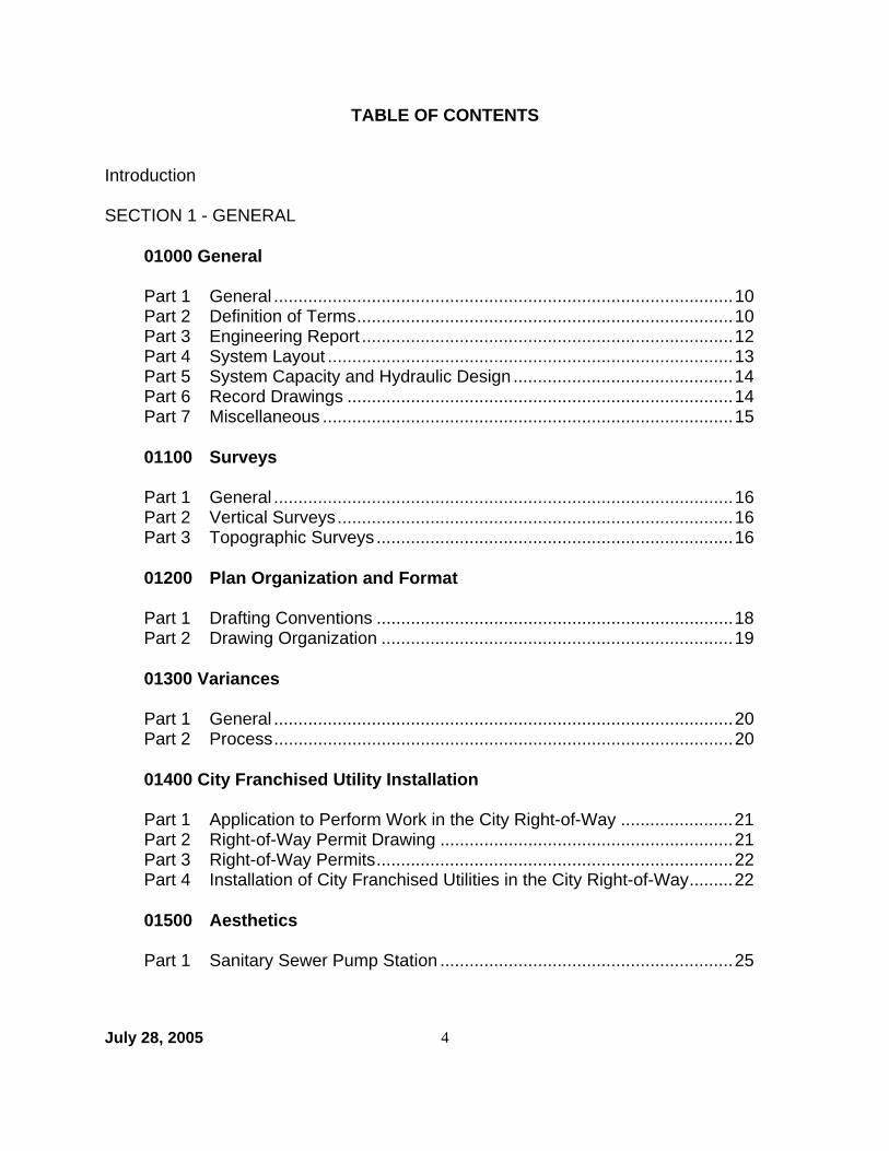
TABLE OF CONTENTS Introduction SECTION 1 - GENERAL
01000 General Part 1 General ..............................................................................................10 Part 2 Definition of Terms.............................................................................10 Part 3 Engineering Report ............................................................................12 Part 4 System Layout ...................................................................................13 Part 5 System Capacity and Hydraulic Design .............................................14 Part 6 Record Drawings ...............................................................................14 Part 7 Miscellaneous ....................................................................................15 01100 Surveys Part 1 General ..............................................................................................16 Part 2 Vertical Surveys.................................................................................16 Part 3 Topographic Surveys .........................................................................16 01200 Plan Organization and Format Part 1 Drafting Conventions .........................................................................18 Part 2 Drawing Organization ........................................................................19 01300 Variances
Part 1 General ..............................................................................................20 Part 2 Process..............................................................................................20 01400 City Franchised Utility Installation Part 1 Application to Perform Work in the City Right-of-Way .......................21 Part 2 Right-of-Way Permit Drawing ............................................................21 Part 3 Right-of-Way Permits.........................................................................22 Part 4 Installation of City Franchised Utilities in the City Right-of-Way.........22 01500 Aesthetics Part 1 Sanitary Sewer Pump Station ............................................................25
July 28, 2005 5
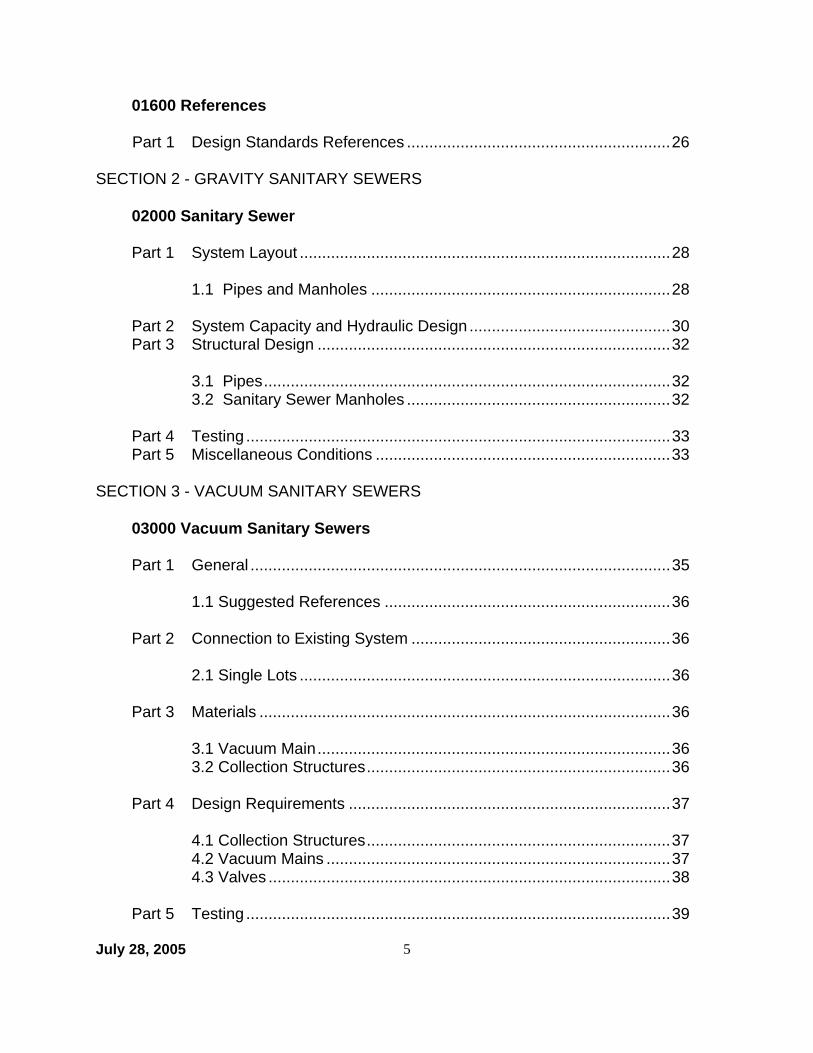
01600 References Part 1 Design Standards References ...........................................................26
SECTION 2 - GRAVITY SANITARY SEWERS
02000 Sanitary Sewer Part 1 System Layout ...................................................................................28 1.1 Pipes and Manholes ...................................................................28 Part 2 System Capacity and Hydraulic Design .............................................30 Part 3 Structural Design ...............................................................................32 3.1 Pipes...........................................................................................32 3.2 Sanitary Sewer Manholes ...........................................................32 Part 4 Testing ...............................................................................................33 Part 5 Miscellaneous Conditions ..................................................................33
SECTION 3 - VACUUM SANITARY SEWERS
03000 Vacuum Sanitary Sewers Part 1 General ..............................................................................................35 1.1 Suggested References ................................................................36 Part 2 Connection to Existing System ..........................................................36 2.1 Single Lots ...................................................................................36 Part 3 Materials ............................................................................................36 3.1 Vacuum Main...............................................................................36 3.2 Collection Structures....................................................................36 Part 4 Design Requirements ........................................................................37 4.1 Collection Structures....................................................................37 4.2 Vacuum Mains .............................................................................37 4.3 Valves ..........................................................................................38 Part 5 Testing ...............................................................................................39

July 28, 2005 6
Part 6 Miscellaneous ....................................................................................42
SECTION 4 - SANITARY SEWER PUMPING STATIONS 04000 Sanitary Sewer Pumping Stations Part 1 General ..............................................................................................44 1.1 Suggested Referenced ...............................................................44 Part 2 Station Location .................................................................................44 2.1 Service Area ...............................................................................44 2.2 Site Availability............................................................................45 Part 3 Types of Stations ...............................................................................45 3.1 Wet Well/Dry Well .......................................................................45 3.2 Suction Lift ..................................................................................45 3.3 Submersible................................................................................46 3.4 Vacuum.......................................................................................46 Part 4 Mechanical Design.............................................................................46 4.1 Pump and Motors ........................................................................46 4.2 Piping System..............................................................................47 4.3 Valves ..........................................................................................48 4.4 Ventilation ....................................................................................48 Part 5 Structural Design ...............................................................................48 Part 6 Electrical Design ................................................................................49 6.1 Power Source ..............................................................................49 6.2 Motor Control Center (MCC)........................................................49 Part 7 Architectural Design...........................................................................51 Part 8 Miscellaneous ....................................................................................52
SECTION 5 - FORCE MAINS 05000 Force Main Part 1 System Layout ...................................................................................54 Part 2 System Capacity and Hydraulic Design .............................................54 Part 3 Structural Design ...............................................................................55

July 28, 2005 7
3.1 Strength Design ..........................................................................55 3.2 Thrust Protection Design ............................................................55 Part 4 Testing ...............................................................................................56 Part 5 Miscellaneous Considerations ...........................................................56
SECTION 6 - WATER PUMPING STATIONS 06000 Water Pump Station Part 1 General ..............................................................................................58 1.1 Pumping Stations........................................................................58 1.2 Water Storage Tanks ..................................................................58 1.3 Suggested References ...............................................................58 Part 2 Capacity and Hydraulic Design..........................................................59 2.1 Hydraulic System Modeling ........................................................59 2.2 Pump Sizing................................................................................59 2.3 Storage Facility Sizing ................................................................59 Part 3 Facility Design ...................................................................................59 3.1 Site Plan Requirements ..............................................................59 3.2 Mechanical..................................................................................59 3.3 Structural ....................................................................................60 3.4 Electrical .....................................................................................60 3.5 Architectural................................................................................62 3.6 Miscellaneous .............................................................................62 Section 7 - Water Transmission and Distribution Facilities 07000 Water Transmission and Distribution Facilities Part 1 System Layout ...................................................................................64 1.1 Pipes...........................................................................................64 1.2 Valves .........................................................................................64 1.3 Services and Meters ...................................................................64 1.4 Fire Hydrants ..............................................................................64 Part 2 System Capacity and Hydraulic Design .............................................66

July 28, 2005 8
Part 3 Fire Protection ...................................................................................67 Part 4 Structural Design ...............................................................................67 4.1 Strength Design ..........................................................................67 4.2 Thrust Protection Design ............................................................67 Part 5 Miscellaneous Considerations ...........................................................68
SECTION 8 - SUPPLEMENTAL PROVISIONS OR AMENDMENTS Appendix - Standard Forms
Form No. Title F-1 Standard Legend

9
SECTION 1 GENERAL

December 2002 10
Section 01000 - General Part 1 - General
1.1 The design of public utility water and sanitary sewer systems shall be prepared and certified in accordance with Title 54.1, Chapter 4 of the Code of Virginia, or as amended.
1.2 Sanitary sewer, sewage pump station, and sewer force main designs shall
conform to the Commonwealth of Virginia "2002 Sewage Collection and Treatment Regulations@ and the requirements of the Department, whichever is more restrictive.
1.3 Water distribution main, transmission main, water pumping station, and water
storage facility designs shall conform to the Commonwealth of Virginia "Waterworks Regulations November 15, 1995" and the requirements of the Department, whichever is more restrictive.
1.4 When the project design is under the jurisdiction of other State or Federal
agencies and the design requirements are in conflict, the more restrictive requirements shall govern.
Part 2 - Definition of Terms
2.1 "CIP" means a project funded under the City of Virginia Beach Capital Improvement Program.
2.2 ACity@ means the City of Virginia Beach. 2.3 "Comprehensive Plan" means the Department of Planning document
consolidating the major elements of various planning reports and establishing an overall guide for the City of Virginia Beach's zoning and plan of growth.
2.4 "Control Center" means the Department=s central facility utilized in
monitoring the public sanitary sewer pumping stations, the water pumping stations, storage facilities, and monitoring points.
2.5 "Department of Public Utilities" shall be referred to as the "Department."
The Department owns, maintains and operates the public water distribution and sanitary sewer collection system for the City of Virginia Beach.

11
2.6 "Developer" means any property owner, or any person or group with written authorization from the property owner, who intends to improve or to construct improvements upon a given property.
2.7 "Development Services Center (DSC)" is the agency in the Department of
Planning which accepts site development plan submittals, coordinates plan review with various City agencies, and issues either approved plans or comment letters identifying plan deficiencies.
2.8 "Distribution Main" means a water main used for distributing water within a
specific area or region of a water system.
2.9 "Engineer" shall mean the engineering consultant, tasked with the design of a project by the Department or Developer.
2.10 "HRSD" shall mean Hampton Roads Sanitation District.
2.11 "Interceptor Force Main" means a force main that receives flows from one
or more sewage force mains and conveys such flows to a point for treatment or disposal.
2.12 "Lateral" means the pipe or conduit conveying wastewater in a gravity sewer
from a property to the public gravity sewer system and has no other common sewer tributary to it.
2.13 "Main" (i.e. water, gravity sanitary sewer, vacuum, force) means a gravity,
vacuum, or pressure pipe that conveys water or wastewater from one point to another.
2.14 "Peer review" means the review of construction plans by various agencies
and divisions of the City of Virginia Beach as determined and coordinated by the Project Manager.
2.15 "Private Force Main" shall refer to any force main that is privately owned
and maintained.
2.16 "Private Utilities" shall refer to any gravity sewer, force main, sewage treatment plant or water supply system that serves residential subdivisions or other groups of uses or structures and is not owned and maintained by the Department.
2.17 "Project Area" shall mean the area where work is to be performed either by
the City of Virginia Beach or a developer.

December 2002 12
2.18 "Project Cost" shall mean the total dollar amount required for funding a project including engineering study, design, right-of-way and /or easement acquisition, construction costs, and contingencies. Developer projects shall also include a cost for inspection and support.
2.19 AProject Inspector@ shall mean the Department=s construction inspector
assigned to a project for constructing CIP or developer projects.
2.20 "Project Manager@ shall mean the Department's engineer assigned to a CIP project for planning, design or construction.
2.21 "Public Sanitary Sewer System" is any sanitary sewer facility or line owned
and maintained by the Department.
2.22 "Public Water System" is any water facility or line owned and maintained by the Department.
2.23 "Service Line" means a pipe or conduit conveying water from a water
distribution main to the water meter of any individual property.
2.24 "Shall" means a mandatory requirement.
2.25 "Site Plan" is the detailed drawings indicating all building layout, land improvements including landscape treatments, drainage, grading, utilities, right-of-way improvements, erosion control and details which may be required by city ordinance.
2.26 "Transmission Main" means a water or force main, used for conveyance
from one area or region of the system to another. Water transmission mains are generally 12-inch diameter and larger. Many sewerage transmission mains in the City are owned and operated by HRSD.
2.27 "VDH" is the Virginia Department of Health.
Part 3 - Engineering Report
3.1 The purpose of the engineering report is to study the available options to determine the best means of integrating the proposed utility improvements into the existing system, while taking into account the potential for future system extensions. The report shall, at a minimum, address hydraulic conformity, an evaluation of alternatives, project cost, maintenance cost, easement and property acquisition, neighborhood and traffic impact, with a summary of conclusions and a recommendation for design/construction.

December 2002 13
3.2 For developer projects, the proposed system layout shall be identified at the time of preliminary subdivision submittal. The layout shall include, at a minimum, main configuration and sizing, connections to existing systems, rim and invert elevations, pump station location, proposed finished floor elevations, and hydraulic calculations.
3.3 A comprehensive engineering report shall be submitted for CIP projects when
required by the scope of services of the Engineering Service Contract.
Part 4 - System Layout
4.1 The layout of the system shall be consistent with the recommendation of the approved Engineering Report as approved by the Department, unless directed otherwise by the Department.
4.2 The layout of utility system improvements shall be situated to provide logical
system extensions to the existing system, and, where appropriate, shall be situated to accommodate future system extensions.
4.3 All utilities and their appurtenances owned and maintained by the
Department shall be located in public rights-of-way, Department owned property, or permanent public utility easements. Permanent public utility easements may be appropriate when there is no feasible right-of-way alternative available, but must be reviewed and approved by the Department variance process.
4.4 The minimum width for a shallow (less than six (6) foot depth) single public
utility placed in a permanent public utility easement shall be twenty (20) feet, except when widening existing right-of-way or public utility easement. Thirty (30) feet is the required width when shallow water and shallow gravity sewer or a single deep (greater than six (6) foot depth) water or gravity sewer line is placed in a public utility easement. Note, buildable lot area currently excludes any easement over twenty (20) feet.
4.5 Provide adequate working space for construction and maintenance of the
system.
4.6 Existing underground utilities, private and public and structures shall be located and shown in the system layout.

December 2002 14
Part 5 - System Capacity & Hydraulic Design
5.1 Improvements to the public systems shall be sized such that the existing system capacity is not exceeded. Where appropriate, up sizing for future system demand should be incorporated to provide for logical, cost effective and efficient system extensions.
5.2 The system demand computation and design shall be based on the City's
Comprehensive Plan, existing use, or existing zoning, whichever is greater. An analysis shall be prepared tabulating numbers and types of structures served or proposed to be served. Service area boundaries must be identified.
5.3 Developers are required to provide facilities with capacity sufficient for the
type of development proposed and so related to existing or potential surrounding development as to form a logical part of a coordinated system. The City may have the developer "up-size" or deepen facilities to accommodate future customers through a developer Cost Participation Agreement where the City pays for the additional costs of the accommodation for future needs or existing needs on or off-site.
Part 6 - Record Drawings
6.1 Record drawings for Department or Developer projects shall be prepared by the Engineer; based on marked up plans provided by the contractor and submitted to the Department upon completion of the work. These drawings must show changes from the construction plans, conditions found during the work, and conditions that changed during the work.
6.2 The detail and elements of data, the accuracy, and format for record
drawings are not fully developed at this time. Once available, they will initially be posted in Section 8 until incorporation into this section.
6.3 Design files shall be corrected and submitted in digital and mylar format as
record drawings.
6.4 Lateral inverts at property/right-of-way line shall be indicated.
December 2002 15
Part 7 - Miscellaneous
7.1 A jack and bore installation is required where open cutting is not permitted, typically at railroad crossings or high volume roadways. Steel casings, with leak detectors, are required for all jack and bore installations. Other methods such as microtunneling, tunnel liner plate or directional drilling may also be considered.
7.2 Corrosion potential shall be analyzed by the Engineer and corrosion
protection shall be provided as necessary. Stray voltage testing and geotechnical data must be evaluated to ensure adequate protection.
7.3 Ductile iron pipe is required for any system placed within an easement.
7.4 Calculations submitted to the Department for review/approval shall be typed.
7.5 Contact the HRSD Interceptor Engineer at P.O. Box 5911, Virginia Beach,
Va, 23471-09111, (757) 460-2261. *** End of Section ***
December 2002 16
Section 01100 - Surveys Part 1 - General
1.1 All surveys should be made in accordance with recommended standards of National Geodetic Survey (NGS) with accurate and legible survey notes kept in digital format, or hardback survey notebooks, properly numbered and indexed for identification.
1.2 All survey records used in the furtherance of the work under a CIP design
contract (including all aerial negatives and exposed prints, manuscripts, field books, and tracings) shall become the property of the Department.
Part 2 - Vertical Surveys
2.1 Vertical control shall be based on the mean sea level-datum as established by the National Geodetic Vertical Datum (NGVD) of 1929 (1972 adjusted) with a loop closure of not less than 0.03 feet times the square root of the distance in miles around the loop.
2.2 Vertical surveys shall consist of:
$ profiling the proposed construction centerline, $ setting bench marks along the line of proposed construction to the
accuracy as set forth in 2.1 above, $ delineating the elevation of the topographic features, as set forth in
Part 3 below.
Part 3 - Topographic Surveys (TOPO)
3.1 Horizontal control shall be based on the Virginia State Plane Coordinate System, South Zone (NAD 1983 (1986 adjusted) datum expressed in international feet values) with a traverse closure of not less than 1:20,000. The Engineer shall establish a survey baseline with sufficient coordinates and control points to accurately locate the horizontal alignment of the project: The survey shall be suitable for construction layout and record drawing purposes.
3.2 Topographic surveys shall consist of obtaining and mapping horizontal and
vertical data for all physical features which may influence utilities design.
3.3 Design data is generally limited to those physical features including utility castings, manhole inverts, building locations and type, ground elevations for contour determination, roadway data, bodies of water, landscaping features, fences, property lines, and rights-of-way. The lowest finished floor elevation

December 2002 17
shall be obtained to the nearest 0.1 foot for gravity sewer projects.
3.4 The design shall include underground utilities location by research of existing records and field verification.
3.5 Test pits shall be required to determine the exact location of underground
utilities for critical conflict situations. *** End of Section **

18
Section 01200 - Plan Organization and Format Part 1 - Drafting Conventions
1.1 Symbols and designations for existing facilities and proposed utilities systems should conform to the Standard Legend contained in Appendix Form No. F-1.
1.2 Digital design and related files will be prepared in an accepted format. CAD
should use Microstation version SE. Reports, calculations and tables, should use Microsoft Office 2000. Otherwise, all documents should be prepared in PDF format.
1.3 The scale shall be selected based on the type of construction and the degree
of congestion in the work area. Typically, horizontal scales of 1"= 40' or 1"= 25' and vertical scales of 1"= 4' or 1"= 2.5' are appropriate.
1.4 Pump stations shall typically be drawn to 3/8" = 1' scale. Details shall be
drawn to appropriate scale. Site Plans shall be at 1" = 20'.
1.5 Stationing for pipeline construction projects shall be shown from left to right beginning at 0 + 100.00.
1.6 All construction drawings shall be prepared on 24"x 36" sheets. Limit actual area used to 22"x 34" to allow for half-sheet printing.
1.7 Sufficient coordinates, based upon the Virginia State Plane Coordinate
System, South Zone (NAD 1983 (1986 adjusted) datum) shall be shown on the construction plans to accurately locate the horizontal alignment of the project.
1.8 Plans and maps should be oriented, whenever possible, so that the north
arrow points to the top or right of the page or plan sheet.
1.9 All proposed mains shall be shown in plan and profile. A profile is not required for water services or sewer laterals. However, the Engineer shall verify that no conflicts exist between sewer laterals and any crossed underground utilities, e.g., storm drains.
1.10 Show lateral inverts at property/right-of-way lines.

19
Part 2 - Drawing Organization
2.1 Drawings for CIP and Developer subdivision projects shall generally consist of the following types of sheets arranged in the order listed below: (1) Cover Sheet with date and legend (CIP Projects shall include location
map) (2) Index Sheet and/or Index Map Sheet(s) (3) Plan and Profile Sheets (4) General Notes and Details (5) Traffic Control Plans (6) Erosion and Sediment Control Plans
2.2 An index map should be prepared for multi-sheet water or sewer main plans.
The index map shall show a general schematic of proposed mains, valves, hydrants, manholes, etc., with ties to existing utilities, including existing fire hydrants and shall provide a graphic plan sheet index.
2.3 Developer=s individual site development plans are not required to have a
cover sheet, but shall contain sufficient plan and profile sheets to depict the utility layout, standard notes, special details, and other requirements of appropriate City of Virginia Beach ordinances and other agencies.
2.4 City Standard Details may be referred to by the plans. However, details for
special structures or unique situations shall be shown at a suitable scale.
2.5 Title Blocks shall be located at the bottom or vertical edge, right hand margin with the sheet number placed in the extreme lower right hand corner. Information shall include:
(1) Project Name (with CIP number for CIP projects) (2) Drawing Title (3) Engineer's name and address with phone number (for developer
project, also include developer's name and phone number) (4) Scale and graphical scale reference for one (1) inch (5) Revision block (6) Sheet Number
*** End of Section***
July 26, 2005 20
Section 01300 - Variances Part 1 - General
1.1 All utility infrastructure (water, gravity sanitary sewer, vacuum sanitary sewer, force main, pump stations, various appurtenances) whether Department or Developer built, shall adhere to these Design Standards, including any Special Provisions or Amendments.
1.2 The Department provides an opportunity for the Developer and/or Engineer
to request a variance from the Design Standards where appropriate and justifiable to the individual situation. For consideration, the design Engineer must submit the variance request with complete documentation and justifiable support.
1.3 The Department will consider each request on an individual case-by-case
basis. Thus, an approved variance of the Design Standards for one project may not be approved for another project. The Department=s divisions of Engineering, Operations, and Business will, as appropriate, consider the variance request and the potential impacts before approval or denial by the Department's Director.
Part 2 - Process
2.1 To request a variance during the design process, the Developer or Engineer must submit a letter to the Development Service Center (DSC) Utility Engineer with the following:
(1) State and reference the section of the Design Standards for which the
variance is requested. (2) State the change to the Design Standards being sought. (3) Discuss the reason the variance is being requested. (4) Indicate any examples where a similar variance has been granted. (5) Discuss the alternatives to denying the variance request. (6) Include any calculations, model analysis results, drawings, or site
plans, supporting and explaining the request. (7) Discuss any cost considerations relating to the alternatives.
2.2 The DSC Utility Engineer will forward the request to the Department for
consideration. The review process generally requires thirty (30) working days.
**** End of Section ****

July 26, 2005 21
Section 01400 - City Franchised Utility Installation (Power, Communications, and Gas) Part 1 - Application To Perform Work in the City Right-of-Way
1.1 Prepaid applications may be obtained from the Department of Planning/Permits and Civil Inspections, Monday through Friday 8:30 am until 5:00 pm.
1.2 The application shall contain the following information and shall be submitted
to Civil Inspections for routing and simultaneous review: (1) Company name (2) Signature of applicant responsible for the work (3) Company address (4) Company phone and fax number (5) Company project file number (6) Contractor name and phone number (7) Type and description of work (including linear footage) to be
performed (be specific) (8) Indicate whether an open cut test hole for utility verification is needed.
Indicate type of cut, e.g. (1' x 1'), and how many are needed. An Open Cut letter shall be submitted with the permit application.
(9) Provide address / location of work, nearest cross street, name of subdivision and name of district
(10) Indicate whether proposed utility work is within the limits of a Capital Improvement Project (C.I.P). If yes, provide C.I.P. job number
(11) Provide proposed dates for start and completion of construction Part 2 - Right-of-Way Permit Drawing
2.1 All proposed utilities shall be highlighted.
2.2 May be submitted using existing site plans, record drawings, intersection
drawings, etc. or drawn by C.A.D. software or hand drawn. All drawings shall be neat and legible. NOTE: The use of existing drawings will not eliminate any requirements listed in Section 2.4 below.
2.3 Scaled drawings are not required but shall be adequately sized based on the
degree of congestion within the limits of all proposed and existing utilities.
2.4 All permit drawings shall show the following: (1) Property line or city right-of-way line (and labeled as shown) (2) Horizontal distance between right-of-way line or public easement line
to the nearest existing public utility (3) Curb & gutter, edge of pavement, sidewalks, and driveways (and

July 26, 2005 22
labeled as shown) (4) All water mains, detector checks, fire hydrants, water valves, gravity
sewer mains, manholes, gravity sewer services (if available), sewer force mains (including HRSD force mains), and force main valves with depth indicated for each
(5) All vacuum sewer mains, valve pits, and service lines with depth indicated for each
(6) Diameter of all existing water mains, sewer mains and force mains being crossed or within 10 feet of the proposed utility.
(7) Horizontal distance between existing public utilities and all proposed utilities (may be referenced from edge of pavement or curb)
(8) What each end of all proposed utilities ties into or where it crosses out of the city right-of-way or easement, i.e. from pedestal to pole or from pole to property line.
(9) Linear footage of all cable, conduit or piping (10) North arrow (11) Match line station or sheet number if applicable (12) BMP=s within limits of proposed utility installation (13) Street name, address, subdivision name, and district (14) Permit number (15) Show all utility easement(s) within proposed work area
Part 3 - Right-of-Way Permits
3.1 All work within the City=s right-of-way or easement requiring excavation,
directional drilling or jacking that may disturb curb and gutter, driveways, pavement, landscaping, traffic, etc. requires a permit. Any private utility company performing work in the right-of-way without a permit is subject to revocation of their franchise agreement with the City and any other penalties allowed by law.
3.2 The private utility company acquiring the permit shall be held responsible for
any damages to the Department's infrastructure and the Department=s cost associated with the repairs.
Part 4 - Installation of City Franchised Utilities in the City Right-Of-Way
4.1 All work site locations shall be faxed (757-426-5778) or phoned in (757-427-
4171) to the Department's Engineering Division no later than 9:00 am daily.
4.2 (1) The minimum depth for power and communication cables (with the exception of road bores shall be in accordance with National Electric Safety Code (NESC), Table 353-1 Supply Cable or Conductor Burial Depth. All road bores shall be at a minimum depth of 36-inches from finished grade to top of cable or conduit.

July 26, 2005 23
(2) The minimum depth for gas mains and services shall be 36-inches.
4.3 Private utility installations must maintain a minimum 24-inch (2 foot) vertical
separation and a minimum 36-inch (3 feet) edge to edge horizontal separation from all the Department's infrastructure. The depth and size of the Department's infrastructure may increase horizontal separation distances.
4.4 When crossing over or under the Department's infrastructure, the contractor
shall comply with the section titled "Requirements for Trenchless Excavation" found in the Virginia Professional Excavator's Manual. These rules are mandated by the State Corporation Commission, Division of Energy Regulation and comply with the rules for enforcement of the Underground Utility Damage Prevention Act. The requirement states, "The excavator shall visually check the drill head as it passes through pot holes, entrances, and exit pits; and if the depth indicated by the locating device is lower than the bottom of the pot hole or pit, the excavator shall cease boring until the hole/pit can be hand excavated further to maintain a visual inspection of the drill head."
In areas where the City will only allow a 1-foot by1-foot test pit, visually checking the drill head pass through the test pit cannot be enforced. When crossing the Department's infrastructure that is not limited by a 1-foot by 1-foot test pit, the private utility is allowed to maintain 36-inches or greater edge to edge vertical separation in lieu of visually checking the drill head pass through the test pit. Vertical separation between 24-inches and 36-inches is permitted providing the drill head is visually checked as it passes through the test pit. At no time shall the drill head be allowed to pass the Department's infrastructure with less than 24-inches of separation.
4.5 The HRSD Interceptor Engineer shall be notified 48 hours prior to crossing or
tapping HRSD force mains.
4.6 The contractor shall have a complete copy of the approved right-of-way permit on site at all times.
4.7 The contractor shall have a complete copy of The Virginia Underground Utility Damage Prevention Act and Chapter 309 of The Rules For Enforcement Of The Underground Utility Damage Prevention Act on site at all times.
4.8 Notify Miss Utility (1-800-552-7001) at least forty-eight (48) hours before
beginning any installation / construction. 4.9 The permittee or authorized representative of the private utility shall contact

July 26, 2005 24
the Department's Engineering Division (757-427-4171) twenty-four (24) hours prior to verification of existing utilities when using the open cut method.
5.0 If damage to the Department=s facilities occurs during the private utility
installation, the permittee or authorized representative shall notify the Department=s Engineering Division (757-427-4171) and the Operations Division (757-563-1400) to effect the necessary repairs.
**** End of Section ****

July 26, 2005 25
Section 01500 - Aesthetics Part 1- Sanitary Sewer Pump Station
1.1 The above ground structure of sanitary sewer pump station as it pertains to roofs, roof shingles, brick mortar, bricks, cornice trim, etc., may normally conform to the Franco Georgian architecture. However, the facility must blend harmoniously into its environment, especially in historically significant areas, and architecture appropriate for the environment shall be determined as listed below.
1.2 Site design shall best balance the existing natural features at the site with
access and circulation needs. Landscaping shall be used to screen and buffer the facility as well as obscuring external features that do not blend well with the surrounding area.
1.3 Building design shall provide a structure that is compatible with its
surroundings by incorporating design elements that provide visual interest consistent with the area. Design elements shall balance material texture, roof lines, wall plane projections or recesses with durability and maintainability.
1.4 The public involvement process of the Department requires a public meeting
before construction of any new structure. The meeting shall be held early enough in the design effort so that public input is fully incorporated into final design.
**** End of Section ****

July 26, 2005 26
Section 01600 - References Part 1 - Design Standards References ACI 211 - Guide for Submittal of Concrete Proportions ACI 212 - Chemical Admixtures for Concrete ACI 301 - Specifications for Structural Concrete ACI 318 - Building Code Requirements for Structural Concrete ACI 350 - Wastewater Facilities AWWA - # Sizing Water Services Lines & Meters (M22)
# Water Meters - Selection, Installation, Testing and Maintenance (M6) # Distribution System Requirements for Fire Protection (M31)/ISO
# Ductile-Iron Pipe and Fitting (M41) # Distribution Valves: Selection, Installation, Field Testings, and Maintenance (M44)
City of Virginia Beach Administrative Directive 3.17, AWind Speed Design Criteria for New Buildings and Public School Projects@ City of Virginia Beach Department of Public Utilities - Comprehensive Water Study (July 1991) DIPRA - Thrust Restraint and Corrosion Protection Fair, Geyer, & Okum - Water Supply & Wastewater Removal Great Lakes - Upper Mississippi River Board of State Public Health & Environmental Managers - Recommended Standards for Wastewater Facilities Hydraulic Institute - Engineering Data Book Standards NEC - National Electrical Code NFPA - National Fire Protection Handbooks Sanks - Pumping Station Design, 2nd Edition Uni-Bell Plastic Pipe Association - Handbook of PVC Pipe Water Environment Federation (WEF) -
Design of Wastewater and Stormwater Pumping Stations (MOP FD -4) Gravity Sanitary Sewer Design and Construction (MOP FD-5)
**** End of Section ****

27
SECTION 2 GRAVITY SANITARY SEWER

December 2002 28
Section 02000 - Gravity Sanitary Sewer Part 1 - System Layout
1.1 Pipe and Manholes
1.1.1 Gravity Sanitary Sewer Location
1.1.1.1 Gravity sanitary sewers shall be located in publicly owned rights-of-way in the center of streets avoiding the wheel path, if practical.
1.1.1.2 Gravity sanitary sewers may be permitted in easements
only when no feasible alternative exists and the Department approves such easement through its variance process. The easement shall provide at least twenty (20) feet width for gravity sanitary sewers with depth six (6) feet or less and at least thirty (30) feet width for gravity sanitary sewers with depth six (6) feet or more.
1.1.2 Gravity sanitary sewer laterals shall normally be limited to one (1)
service per site (duplexes are allowed two (2)) unless otherwise directed by the Department. Minimum size shall be four (4) inches in diameter unless an increase in size is justified and approved by the Department.
1.1.3 Lateral cleanouts shall be placed at the right-of-way lines. If not
feasible at the right-of-way, a variance for placing the cleanout in an appropriately sized easement may be considered by the Department. Show invert elevations at the right-of-way line.
1.1.4 Avoid installing cleanouts in existing or proposed sidewalks,
driveways, paved areas or drainage ways.
1.1.5 Minimum cover for gravity sewers shall be twenty-four (24) inches for ductile iron pipe and thirty-six (36) inches for other pipe.
1.1.6 The maximum distance between manholes is 400 feet.
1.1.7 Sanitary sewer tributary flow lines shall intersect in manholes at
angles of 90 degrees or less with the main flow line and channel shaping is required. See the Standard Details for Invert Shaping.

December 2002 29
1.1.8 A tenth of a foot (0.1) drop is required in sewer manholes from inlet to outlet invert.
1.1.9 Combined sewers are not allowed.
1.1.10 Sanitary sewer lines shall be designed with uniform slope between
manholes.

December 2002 30
Part 2 - System Capacity and Hydraulic Design
2.1 Design shall be based on maximum dwelling/room/apartment unit densities as shown in the following chart:
Zoning
Maximum Density (Unit/acre)
Unit Flow (gpd)
Lot Coverage
Zoning
Maximum Density (Unit/acre)
Unit Flow (gpd)
Lot Coverage
A12
12
400
1
PDH-1
4.25
400
1
A18
18
400
1
PDH-2/A36
36
400
1
A24
24
400
1
A36
36
400
1
R2.5
9
400
1
R7.5
3.5
400
1
AG1
1
400
1
R10
3
400
1
AG2
1
400
1
R15
2.25
400
1
R20
1.7
400
1
B1
43.56
250
0.33
R30
1.1
400
1
B1A
87.12
250
0.33
R40
0.8
400
1
B2
87.12
250
0.33
R5D
6
400
1
B3
108.9
250
0.33
R5R
6
400
1
B3A
108.9
250
0.33
R5S
6
400
1
B4
36
250
1
RT1
190
130
1
H1
80
130
1
RT2
120
130
1
RT3
160
130
1
I1
108.9
250
0.33
RT4
18
400
1
I2
108.9
250
0.33
O1
43.56
250
0.25
02
87.12
250
0.25

December 2002 31
2.2 Average Flow. The below calculation shall be used for determining average flows for the above zoning(s):
Qavg = Acreage x Max. Density x Unit Flow x Lot Coverage
2.3 Peak Flow. The peak factor is 2.5; thus Qpeak = 2.5 x Qavg
2.4 Exceptions to the above requirements will be considered only if impractical to
provide required depths and a variance is requested by the Engineer and approved by the Department.
2.5 Sanitary sewers shall be designed for a minimum flow velocity of two feet per
second for design flows. Manning=s formula for pipe roughness (An@) shall be based on the pipe material.
2.6 The following table represents the minimum grades for gravity sanitary
sewers:
Sanitary Sewer Size
Minimum Slope per 100 Feet
4-inch (lateral only)
1.0
6-inch (lateral only)
0.63
8-inch
0.40
10-inch
0.28
12-inch
0.22
14-inch
0.17
15-inch
0.15
16-inch
0.14
18-inch
0.12
21-inch
0.10
24-inch
0.08
27-inch
0.067
30-inch
0.058
36-inch
0.046
December 2002 32
Part 3 - Structural Design
3.1 Pipes
3.1.1 Ductile Iron Pipe - Shall meet requirements of ANSI/AWWA C151/A21.51-2002, thickness class 52 with a single thickness of cement/mortar lining with bituminous seal coat. Thickness design shall meet requirements of ANSI/AWWA C150/A21.50-2002. For burial depths exceeding those allowed by the class, pipe and fittings of sufficient wall thickness shall be provided. Cement-mortar linings shall meet requirements of ANSI/AWWA C104/A21.4. Structural requirements must be considered in the design of all sewers and the proper strengths determined for the sewer pipe materials being specified.
3.1.2 Polyvinyl Chloride (PVC) - shall meet requirements of ASTM D 3034-
81 and shall have Integral Bell, Gasketed Joint Pipe with a dimension ratio (dr) of 35 and a minimum stiffness (ps) of 46 psi @ 5% deflection.
3.1.3 Fittings and gaskets for PVC and Ductile Iron Pipe shall meet criteria
listed in the Department's Amendments to the VDOT Road and Bridge Specifications, January 1994, for pipe, Section 520.02 - Materials.
3.1.4 Sanitary sewers twelve (12) feet or deeper or with less than three (3)
feet cover shall be ductile iron pipe. Pipe depth shall not exceed sixteen (16) feet (unless approved by a variance).
3.1.5 Ductile iron pipe shall be used when a gravity sanitary sewer is
approved for placement within an easement.
3.2 Sanitary Sewer Manholes
3.2.1 Manholes deeper than 12 feet shall be a minimum of 5 feet in diameter for the entire depth below the cone.
3.2.2 Drop manholes shall use inside drop connections and must be a
minimum of five (5) feet in diameter. Drop manholes should be avoided when possible by adjusting the depth and slope of the main. When the invert of the connecting tributary sewer exceeds the invert of the main by two (2) feet or more, an inside drop shall be used.
3.2.3 Sewer manholes receiving flows from a sanitary force main shall
direct discharge to the downstream pipe and shall be adequately

December 2002 33
protected against hydrogen sulfide attack with a coating or lining system approved by the Department. See the Department=s Standard Details for saxophone connection.
3.2.4 The maximum depth for collection manholes serving sewage pumping
stations is sixteen (16) feet (pipe invert).
Part 4 - Testing
4.1 See Section 520.04 - Testing of the Department=s Amendments to the VDOT Road and Bridge Specifications, January 1994.
Part 5 - Miscellaneous Conditions
5.1 Sewer laterals shall have a minimum of six (6) inch vertical clearance between curbs, gutters, sidewalks, driveways, and ramps. The minimum depth of cover at ditch crossings shall be eighteen (18) inches from the lowest likely ditch invert.
5.2 The length of the typical service lateral shall not be in excess of 75 feet.
5.3 The maximum number of service laterals entering a manhole shall be four
(4), except for inside drop connections, where the maximum shall be two (2). Laterals and drops shall not conflict with manhole steps.
5.4 Depth of service lateral shall be sufficient to provide adequate gravity service
to the property. The Engineer shall indicate on the plan the lateral depth invert elevation at the right-of-way line.
5.5 Service laterals shall normally be the same material as the sewer main
unless otherwise required. 5.6 Terminal or mainline cleanouts or end of line manholes shall have a
maximum depth of 4.5 feet and a maximum pipe length of 150 feet.
5.7 Witness posts for manholes are required within easements.
5.8 When connecting to an existing pre-cast concrete manhole, core drill and install an approved flexible connector for the pipe.
5.9 When connecting to an existing brick manhole, drill and knockout the brick
and use a water stop on the connecting pipe, and fully embed in non-shrink mortar, to produce a permanent water tight seal.
5.10 See Standard Details for Frame and Cover requirements.

December 2002 34
5.11 See Department's Amendments to the VDOT Road and Bridge
Specifications, January 1994, system material, construction and testing requirements.
5.12 Any discharge from a restaurant to the public system must have pre-
treatment (i.e., pass through a grease trap prior to discharge into the public system).
**** End of Section ****

December 2002 35
SECTION 3
VACUUM SANITARY SEWERS

December 2002 36
Section 03000 - Vacuum Sanitary Sewers Part 1 - Suggested References
1.1 Suggested References
1.1.1 EPA Manual - Alternative Wastewater Collection Systems October 1991
1.1.2 AIRVAC Design Manual 2000
Part 2 - Connection to Existing System
2.1 Single Lots
2.1.1 Single lots connect to an existing valve pit or a vacuum valve pit installed by the Department. Four lots are typically serviced by a single valve pit.
Part 3 - Materials
3.1 Vacuum Main
3.1.1 Pipe for mains and service lines shall be solvent weld PVC thermoplastic pipe, schedule 40, SDR 21 or class 200 in sizes 3-inch, 4-inch, 6-inch, 8-inch, or 10-inch. Fabricated PE fittings shall be made from identical pipe.
3.1.2 Fittings shall be Schedule 40 (pressure) type. Fittings include: wyes -
for incoming branches or valve crossovers, 45 degree ells - for making changes in direction and fabricating profile changes, and concentric reducers - for making changes in main size. Fittings for pipe diameters 10-inches or greater shall be ductile iron.
3.2 Collection Structures
3.2.1 Fiberglass collection valve pits shall have a minimum wall thickness of
3/16-inch. Sumps shall be 55-gallon capacity and designed for H20 truck loading at 2-foot depth of cover. Elastomer connections shall be provided for the gravity connections. See the Department=s Standard Details.
December 2002 37
Part 4 - Design Requirements
4.1 Collection Structures
4.1.1 Concentrated flows over 15 gpm from schools, apartments, nursing homes, lift stations, or a number of grinder pumps shall be received at buffer tanks through a splitter box. A maximum of 25 percent of system flow can be controlled by buffer tanks. Buffer tanks should not be placed at project extremities.
4.1.2 High continuous flows must flow to a splitter manhole which will evenly
split the flows to multiple valve buffer tank units. For systems requiring numerous buffer tanks, further restrictions may apply. Contact the Department's Engineering Division (757-427-4171) for assistance.
4.1.3 Elevation differences between structures may require separate valve
pits for those structures.
4.1.4 An anti-buoyancy collar shall be installed at the middle of all non-concrete valve pits at the completion of the backfilling operation, as manufactured by the vacuum system manufacturer.
4.1.5 Design access to valve pits for easy installation/removal/ replacement.
4.1.6 Valve pits will become property of the Department, and be located
within rights-of-way.
4.1.7 When grinder pumps discharge into a valve pit, only one force main per pit is allowed.
4.2 Vacuum Mains
4.2.1 Profile changes should be limited to 12 inches height for 3- and 4-inch
vacuum lines and 18 inches for 6 inches and larger pipe.
4.2.2 Invert elevations shall be shown on profile for all lifts at the extreme end of a vacuum main, a maximum of 2,000 feet of 4-inch vacuum pipe can be used at the approval of the Department. The maximum distance for 3-inch mains is 300 feet.
December 2002 38
4.2.3 Slope requirements - Mains should be designed at a minimum slope of 0.2% slope with profile changes a minimum of every 500 ft. Where the natural ground falls in excess of 0.2% in the flow direction, the vacuum sewer profiles follow the ground slope with no profile changes.
4.2.4 When vacuum mains must ascend a grade multiple lifts must be
placed at a minimum of 20 feet apart.
4.2.5 Systems should be designed for a maximum of 13 feet of vacuum loss due to lifts and 5 feet of vacuum due to friction.
4.2.6 Where a lift is required in a branch sewer prior to entering the main, it
should be made 20 or more feet from the main.
4.2.7 Connections from vacuum valve pits to the mains should be made Aover the top@ of the main but not less than 45 degrees. See the Department=s Standard Details.
4.2.8 Profiles should be provided for all pipe running between the vacuum
valve pit and the vacuum mains.
4.2.9 Gauge taps are placed on the station side of main line valves. (Except on dead-end lines where an extra gauge tap may be required on the up stream side of the main line valve for leak detection.)
4.2.10 Provide four feet of cover for mains.
4.3 Valves
4.3.1 Resilient seated gate valves shall be used as division valves at
branch/main connections, at both sides of a bridge crossing and unstable soil, and at periodic intervals along the route.
4.3.2 Vacuum valves have a maximum capacity of 30 gpm flow, with one
valve capable of handling the total sewage flow from four homes. Where flow exceeds 30 gpm, multiple valves must be used.
4.3.3 High flows from schools, apartments, nursing homes, lift stations, or a
number of grinder pumps may be received at buffer tanks. The maximum flow per valve should be reduced to 15 gpm for these continuous flows.
4.3.4 The distance inside of the valve pit from the 90-degree suction bend
to the 3-inch service pipe cannot be more than 14-3/8 inches.
December 2002 39
4.3.5 Alignment of the 3-inch service line to the 90-degree suction bend
shall be 1/4-inch vertical and 1/8-inch horizontal.
4.3.6 Division valves shall be installed at branch connections with lines exceeding 300 feet and at intervals no greater than 2,000 feet on main vacuum lines.
4.3.7 Valve boxes located in field (Agrass@) areas shall use a 2'x2'x6" deep
concrete collar. Part 5 - Testing
5.1 Daily Testing. Perform daily testing of all vacuum sewer mains and lateral connections laid as follows:
5.1.1 Plug all open connections with rubber stoppers or temporary caps,
fitted to the pipe by ANo-Hub@ couplings.
5.1.2 Apply a vacuum to 24-inches HG to the pipes and allow the pressure to stabilize for 15 minutes. The test shall be initiated at 24-inch mercury. There shall be no loss of vacuum in excess of 1 percent per hour for a two hour test period.
5.1.3 As pipe is laid, the new section shall be tested in addition to the
previously laid pipe on that main until a division valve is placed. Testing then shall be done with the valve either closed or open as directed by the Department.
5.2 Additional pipe may not be installed until satisfactory test results are achieved
for a given main.
5.3 Trenches must be backfilled at the conclusion of each workday.
5.4 Line flushing. Prior to final acceptance testing, flush lines to remove debris and foreign materials that accumulated in the lines during construction.

December 2002 40
5.4.1 The Developer must flush the entire system at one time upon completion. At least 30 days prior to initiation of flushing operations, the Developer shall submit a proposed plan in writing for conducting line flushing to the Department. The plan shall include the equipment to be used; the segments of the system to be flushed at a given time, the calculated volume of pipe (excluding 3-inch lines) to be flushed, by segment; the location if vacuum valves to be installed to facilitate the flushing operations, and the approximate volume of water to be introduced into the system at the end of each branch line, by segment.
5.4.2 The Developer shall provide appropriate vacuum equipment and
receiving tank to accomplish the work. The vacuum test rig may be temporarily connected to a collection tank to create a vacuum on the system of 20-inches of mercury. The tank must be sized to accommodate one seventh of the volume of the lines being flushed. The Developer shall take all necessary precautions to prevent the entrance of water into the vacuum pumps, if the test rig is used. The Developer shall supply the water for testing.
5.4.3 The following describes the flushing procedure:
5.4.3.1 Place system under vacuum at the downstream end of
the vacuum main segment being flushed.
5.4.3.2 Add water to valve pits at extreme ends of system and cause vacuum valves to operate. (Developer to supply and install valves at the terminal end of each branch line to facilitate flushing.)
5.4.3.3 Utilize system vacuum to transport water and debris to
collection point. Adjust valve timer to allow sufficient air into the system (Approximately 7:1 air to liquid ration).
5.4.3.4 Continue procedure until water entering at collection
point is free of contamination or debris. Developer shall properly dispose of flushing water and debris.
5.4.3.5 Developer shall remove vacuum interface valves and
reinstall temporary caps using 3-inch Fernco couplings.
5.4.3.6 Close division valves to seal off flushed segment.

December 2002 41
5.5 Final testing of vacuum sewer mains
5.5.1 Final testing preparation:
5.5.1.1 Prior to commencing final testing the Developer shall subject each main vacuum line and its associated submains to a vacuum maintained between 16 and 20-inches of mercury. While under vacuum, the last vacuum pot on each submain and main shall be activated in a sequential manner such that air is admitted to the system for a period of 15 seconds. A minimum of four cycles of sequentially activating the pots is required.
5.5.1.2 If after four cycles are completed and water is still being
received at the vacuum pump, the main shall be considered as having failed and it should be the Developer=s sole responsibility to locate and repair the leaks.
5.5.2 Final Testing. Perform required final acceptance testing on complete
system as follows:
5.5.2.1 Test the entire sewerage system to a vacuum of 24-inches Hg, allow to stabilize for 15 minutes. The test shall be initiated at 24-inch mercury. There shall be no loss greater than 1 percent per hour over a 4-hour test period.
5.5.2.2 Developer to provide 48 hours notice to Department
prior to start of test.
5.5.2.3 Developer shall verify all division valves are open prior to beginning of, and shall remain open during, final acceptance test.
5.5.2.4 Final acceptance test shall be recorded on approved
vacuum chart recorder. This chart will not be considered valid unless witnessed by the Department on test equipment at beginning and the end of vacuum test period.
5.5.2.5 Seal system and make ready to place in operation.
December 2002 42
Part 6 - Miscellaneous
6.1 Easements. Location of the lines, valves, or valve pits shall follow the same considerations as that of gravity sanitary sewer, Section 02000, with regard to variance process approval for placement in easement.
6.2 Drawings. Valve pits must be located to allow gravity flow from intended point
of service. Drawings shall note rim elevations and lateral elevations at each valve pit.
6.3 Record Drawings shall provide two Aswing-tie@ points, rim elevation and
lateral length and invert at right-of-way and service address. **End of Section**

December 2002 43
SECTION 4 SANITARY SEWER PUMPING STATIONS

December 2002 44
Section 04000 - Sanitary Sewer Pump Stations Part 1 - General
1.1 Suggested References (Latest edition)
1.1.1 "Standards of Hydraulic Institute".
1.1.2 American Concrete Institute (ACI) 308-01, AGuide to Curing Concrete"
1.1.3 American Concrete Institute (AC1) 318, "Building Code Requirements for Structural Concrete".
1.1.4 American Concrete Institute (ACI) 530-02, ABuilding Code
Requirements for Masonry Structures and Specifications for Masonry Structures@
1.1.5 National Electric Code (NEC).
1.1.6 National Electrical Manufacturers Association (NEMA).
1.1.7 National Fire Protection Association (NFPA).
1.1.8 Standard Rules of American Institute of Electrical Engineers.
1.2 Design shall incorporate Administrative Directive 3.17 - AWind speed Design
Criteria for New City Buildings and Public School Projects@
1.3 All calculations and exhibits pertinent to the pump station design should be computer generated for review. All final design calculations should be supplied in digital format.
1.4 The smallest size station accepted by the Department is 80 gpm (4-inch DIP
discharge). Part 2 - Station Location
2.1 Service Area
2.1.1 Proper location of station is of prime importance within the proposed service area. The ultimate goal is to minimize the number of pumping stations for the area to be served while keeping the depth of the gravity sewer and pump station within a constructible and maintainable depth of sixteen (16) feet at the collection manhole. A

December 2002 45
comprehensive study and report shall be prepared addressing service area boundaries, hydraulic calculations, topography and 100 year flood elevations, as a minimum. See Section 02000, Paragraph 3.2.4 for maximum depth of gravity sanitary sewer.
2.2 Site Availability
2.2.1 As part of the required Engineering report, the recommended site
shall be reviewed for the following environmental concerns: (1) wetlands, (2) EPA Level 1 (Level 2 as needed) environmental assessment, (3) Chesapeake Bay Preservation Act, and (4) Hazardous materials.
2.2.2 Ensure all mechanical and electrical equipment is located above 500-
year flood plain. Design the finish floor elevation to be at least one foot above the 100-year flood elevation.
2.2.3 Stations shall be designed to remain fully operational during a 25-year
flood.
2.2.4 Locate the pump station such that no other structure is within a 100-foot radius of the wet well.
Part 3 - Types of Stations
Only the following types of stations shall be considered:
3.1 Wet Well/Dry Well
3.1.1 Wet well/Dry well pump stations are the preferred station design.
3.2 Suction Lift
3.2.1 Single pit self-priming suction lift stations will be considered on a case-by-case variance basis and must be approved by the Department.
3.2.2 Priming lift for suction lift pumping stations shall not exceed eighteen
(18) feet.
3.2.3 Discharges from suction lift stations shall be made to a manhole in the gravity sanitary sewer system.
3.3 Submersible
3.3.1 Submersible pump station installations will be considered on a case-

December 2002 46
by-case variance basis and must be approved, by the Department, prior to formal plan submittal.
3.4 Vacuum
3.4.1 Vacuum pump station installations will be considered on a case-by-
case basis and must be approved, by the Department, prior to formal plan submittal.
Part 4 - Mechanical Design
4.1 Pumps and Motors
4.1.1 Calculations and schematics shall be prepared showing static head, system friction head losses, minimum and maximum HRSD heads, Total Dynamic Head (TDH), and system head curve for both single and multiple pump operation. System head curve shall show high and low range of operating limits for C factors of both 100 and 120.
4.1.1.1 All calculations submitted for review by the Department
shall be typed.
4.1.1.2 Contact the Hampton Roads Sanitation District Interceptor Engineer for static head conditions. Contact the Department=s Planning & Analysis Bureau for static head conditions in city force main.
4.1.1.3 Pump and motor shall be sized for maximum energy
efficiency.
4.1.2 Sewage pump selection should allow for up sizing or downsizing of impellers as dictated by sewage flows.
4.1.3 Pump motors shall be three phase.
4.1.4 Calculations shall be prepared and submitted to the Department, for
the ventilation system.
4.1.5 Pump station storage volume shall be designed for 10 minute fill time (average theoretical flow) and 6.67 minute pump time for a total of 16.67 minute cycle time.

December 2002 47
4.1.6 To accommodate the entire range of flow and head conditions derived from a system curve analysis or computer modeling techniques, constant speed pumps are preferred; however, two-speed or variable speed are acceptable if required. Motors shall be sized so that the motor can run out on the pump curve without overheating.
4.1.7 Pump stations shall have a minimum of two pumps and shall be
designed such each pump is able to handle the peak flow.
4.1.8 Pumps in which solids pass through the impeller shall be at least capable of passing 3-inch diameter spheres.
4.1.9 Design 6-inch volute submergence for pumps.
4.2 Piping Systems
4.2.1 Internal suction and discharge piping and fittings within a sewage
pumping station shall be flanged ductile iron, Class 52. Full-face fiber reinforced gaskets are required with 150 pound flanges.
4.2.2 Wet well suction piping should be designed to minimize hydraulic
interference and maximize solids movement, as recommended by the Hydraulic Institute.
4.2.3 Suction piping shall be sized for a velocity range from 2 fps to 5 fps
over the range of pumping conditions.
4.2.4 Suction intakes shall be flared.
4.2.5 Horizontal spacing of down-turned suction intakes is generally three (3) times the diameter of the suction flare. Vertical spacing is to be not less than 1/3 and not more than 2 times the diameter of the suction flare off the finished floor.
4.2.6 The influent sewer shall have a gate valve inside the station (wet well)
with a stainless steel riser stem to allow operation from the top slab of the wet well. A corrosion resistant coating shall be applied to the gate valve for protection against hydrogen sulfide gases.
4.2.7 The invert of the influent sewer shall be a minimum of one and one-
half (1-1/2) feet above the wet well high water level.
4.2.8 Discharge piping shall be sized for a velocity range from 2 fps to 8 fps over the range of pumping conditions.

December 2002 48
4.2.9 Air relief piping for a suction lift pump line shall be at least 1.25-inches in diameter.
4.3 Valves
4.3.1 A gate valve must be provided on each suction line for a suction lift or
wet well/dry well pump station.
4.3.2 A check valve and gate valve must be provided on each pump discharge line. These must be located in a separate valve vault that drains back to the wet well. The drain line from the valve vault must be equipped with an anti-backflow device.
4.4 Ventilation
4.4.1 Wet well ventilation shall be mechanical and so arranged to ventilate
the dry well independently.
4.4.2 Continuous ventilation shall provide at least 12 complete air changes per hour. Intermittent ventilation shall provide at least 30 complete air changes per hour.
4.4.3 Non-sparking fans shall be used for ventilation systems.
Part 5 - Structural Design
5.1 The soil bearing capacity and the potential for flotation shall be determined through an appropriate collection and analysis of soils information.
5.2 Sewage pumping station substructures shall be designed in accordance with
ACI 318, ABuilding Code Requirements for Structural Concrete@ and ACI 530-02, ABuilding Code Requirements for Masonry Structures.@
5.3 Minimum wet well dimensions shall be 7' x 7'. The minimum wet well storage
in gallons shall be calculated as (does not apply to submersible stations): Vstorage = 10 minutes x Qavg (gpm). See Section 2.2.1 for determination of Qavg.
5.4 Thrust Restraint. Piping shall be adequately secured to counter the effects of
surge and water hammer. Submit calculations to the Department.
5.5 Design shall incorporate provisions set forth in Administrative Directive 3.17 - "Wind speed Design Criteria for New City Buildings and Public School projects."

December 2002 49
5.6 Separate access must be provided for wet wells. The minimum hatch size is 36-inches by 36-inches.
5.7 The sump pump and volute blow lines discharge point shall be one foot
above the intermediate platform. The discharge pipe shall be PVC material and shall have crosses for fittings to allow cleaning.
Part 6 - Electrical Design
6.1 Power Source
6.1.1 An emergency power connection with manual duplex switch and manual transfer switch shall be required for use with a portable generator (unless an emergency generator is a design requirement for the station).
6.1.1.1 Unless otherwise directed by the Department, pump
stations with a peak capacity of 1000 gpm or less shall have an emergency generator connection with a manual transfer switch.
6.1.1.2 Pump stations with peak capacity greater than 1000
gpm (or those deemed critical by the Department) shall have an on-site emergency generator with an automatic transfer switch.
6.1.2 The Engineer, in conjunction with the local electric utility, shall
determine the availability of adequate electric service to the facility. New underground service shall be 480Y/227 volts, 60 hz, 3 phase, 4 wire.
6.1.3 All electric service shall be underground and meters shall be located
inside the building.
6.1.4 The Remote Telemetry Unit (RTU) and alarm system shall have battery back up rating of at least 24 hours.
6.2 Motor Control Center (MCC)
6.2.1 Liquid Level Control Requirements.
6.2.1.1 Liquid level sensors for wet wells shall be the air bubbler
type with panel face mounted alternating switch.
6.2.1.2 Liquid level controls shall be equipped with dual

December 2002 50
compressors, air flow meters and sufficient tubing to reach the bottom of the wet well.
6.2.2 Controls and Starters. Controls and starters shall be assembled by
the control panel manufacturer in a single panel and shall contain the following:
6.2.2.1 One properly sized main circuit breaker.
6.2.2.2 A step-down dry-type transformer for station voltage of
208Y/120 volt, 3 phase.
6.2.2.3 A circuit breaker and starter for the starting of each pump motor. The breaker shall be properly sized for motor running current and short circuit protection on all three phases of the motor.
6.2.2.4 Reduced voltage starters shall be provided for motors of
75 HP and larger when 230 volt 3 phase is used.
6.2.2.5 One control circuit to provide lead, lag, and alternate operation of pumps with provisions for Hand-Off-Auto operation(HOA). The switch for the pump lockout shall be located approximately 5 feet from the floor of the dry well at the base of the lighted stairway.
6.2.2.6 An HOA switch on the control panel which is to be
lighted in automatic mode only.
6.2.2.7 An adjustable three phase voltage sensor to protect motors and motor starters from single phasing and under-voltage.
6.2.2.8 Individual circuit breakers shall be provided for lights,
ventilation fans, convenience receptacles, heater, sump pump, and RTU receptacle, as required, with step-down transformer for 115 volts AC to control separate circuits and station auxiliaries.
6.2.2.9 The unit heater voltage shall be 230 volts, single phase.
6.2.2.10 The panel shall be UL standard, white on the inside and
exterior painted with gray polyurethane paint. 6.2.2.11 The control panel shall have a NEMA 12 rating. It shall
December 2002 51
be located in the motor room at least 12-inches above the floor.
6.2.2.12 Three-phase motors shall have overload protection.
6.2.3 Alarm Remote Telemetry Unit . The design for each sewage pumping
station shall be provided with a remote telemetry unit , antenna and associated equipment of the same type and compatible with the Department=s telemetry system and specifications. Alarm inputs shall be as specified by the Department but, as a minimum, shall include:
6.2.3.1 High water - wet well
6.2.3.2 High water - dry well
6.2.3.3 Power failure circuit for both primary and alternate
source of power.
6.2.3.4 Test function, intruder alarm and low water alarm.
6.2.4 Internal Wiring
6.2.4.1 Panel and station wiring shall conform to all local building, electrical and fire codes; NEC; Standard Rules of American Institute of Electrical Engineers (AIEE); NEMA; and State Fire Safety Regulations. Panels must have point to point wiring. All cabinets and boxes shall be drawn to scale (for placement) on the plan.
6.2.4.2 All electrical receptacles shall be located four-feet
above the floor.
6.2.4.3 The air compressor shall be located above the panel and shall be provided a separate receptacle.
6.2.4.4 The motor room shall be provided a separate exhaust
fan with louver assembly. Part 7 - Architectural Design
7.1 The above ground structure of sewage pumping stations as it pertains to roofs, roof shingles, brick, mortar, cornice trim, etc., will normally conform to the "Franco Georgian" architecture.
7.2 Refer to Section 01500 of this manual (Aesthetics) for additional information.

52
Part 8 - Miscellaneous
8.1 The Engineer shall determine the need for protection of the pumping station against hydrogen sulfide attack and shall provide the proper equipment if such protection is necessary. Prevention of hydrogen sulfide generation should be an important design consideration. Odor control shall be included in pump station design.
8.2 A lifting beam shall be provided for stations with pumps or motors weighing
less than 2000 pounds. Heavier equipment will be removed using a portable frame and hoist.
8.3 Submersible stations will be provided with an A-frame with a hoist.
8.4 Ceiling lights in the dry well shall be accessible from the stairway.
8.5 Site plan approval is required through the Development Services Center in
accordance with the City's Zoning Ordinance.
8.6 Plans and specifications for Developer pump stations shall be approved by the Department prior to submittal to VDH for approval.
8.7 Cross connection control for sanitary sewer pump stations is required. Use
an RPZ (Reduced Pressure Zone) device. Use a backflow preventer 909QT or approved equal.
8.8 Provision for continuous operation shall be included with the pump station.
8.9 Pump station site surveying shall contain appropriate state coordinate, GPIN,
and address information.
8.10 Mechanical seals are not to be used for dry well pumps, packing glands are to be used instead.
***End of Section***
53
SECTION 5 FORCE MAIN

December 2002 54
Section 05000 - Force Main Part 1 - System Layout
1.1 Sewage force mains shall be located in publicly owned rights-of-way parallel to the center line, if practical, or in easements, in accordance with procedures established in Part 4 of Section 01000, General.
1.2 Sewage force mains shall be laid on a continuous grade, generally 0.10%,
with manual air release valves located at the high points. Minimize or avoid vertical offsets.
1.3 Valves shall be located at approximate 1,000 foot intervals, at tees, at all
changes in pipe diameter, at connections to HRSD force mains, and at City force mains when being manifolded. Valves shall be designed for installation at high points to control flow in the event of a break.
1.4 Additional valves may be required in environmentally sensitive areas. Valves
will be required on both sides of water crossings or bridges.
1.5 Sewage force mains discharging into gravity sewer systems shall have a saxophone connection and shall discharge into a manhole. The manhole requires an approved H2S coating. See the Department=s Approved Products List and Standard Details.
1.6 Sewage force mains discharging into a gravity sewer system should enter the
receiving manhole so that the force main invert is horizontal and level with the center line of the sewer main line in the manhole. A bench shall be constructed to transition the flow from the force main invert down to the main line invert.
1.7 The minimum depth of cover shall not be less than 36 inches. Future
regrading shall be taken into consideration. Part 2 - System Capacity and Hydraulic Design
2.1 A Hazen-Williams coefficient of friction C equal to 100 shall be used for the purposes of design unless the Department has data to justify a different coefficient.
2.2 Where force mains are to be connected to HRSD interceptors or manifolded
to existing City force mains or discharged to a manhole, the design calculations shall include the ultimate hydraulic parameters of the receiving system.
December 2002 55
2.3 The Engineer shall contact HRSD to determine the operating pressure range of the collection force main system.
2.4 The Engineer shall contact the Department=s Planning and Analysis Burerau
for head conditions in the Department=s collection force main system.
2.5 The minimum diameter for a public force main is 4-inches. Part 3 - Structural Design
3.1 Strength Design
3.1.1 Although Class 52, C151 Ductile Iron Pipe is required, strength calculations shall be used to verify the adequacy of the pipe, based on operating pressures, depth of bury, trench width, foundation conditions, and test pressures of 150 PSI for at least two (2) hours.
3.1.2 Assume pipe lining with cement mortar and a bituminous coating in
accordance with ANSI/AWWA C104/A21.4.
3.2 Thrust Protection Design
3.2.1 Thrust protection shall be provided for all bends, tees, reducers, and plugs. Thrust restraint shall be determined by methodology presented in AWWA Manual M-11.
3.2.2 The retainer gland is the normally accepted method of joint restraint.
See the Department=s Approved Products List.
3.2.3 Design calculations and summary table shall be submitted for the restraint lengths.
3.2.4 Representative soils information shall be submitted along the pipe
alignment.
3.2.5 Thrust protection of the existing system may be warranted at offsets, cut-ins, abandonments, etc.
3.2.6 Construction drawings shall reflect, in plan and profile, the location,
type, and extent of required thrust protection and/or provide a restraint table.

December 2002 56
Part 4 - Testing
4.1 See Section 520.04 - Testing of the Department=s Construction Specifications for procedures and requirements.
Part 5- Miscellaneous Considerations
5.1 Sewage force mains subjected to extreme variations in temperature (i.e., attached to bridges or box culverts) shall be designed to account for pipe expansion and contraction and to prevent the line contents from freezing.
5.2 Witness posts shall be provided at each valve location along the path of force
mains installed in easements or right-of-ways in green belts, undeveloped areas, or when directed by the Department. Concrete collars 2'x2'x6" deep are also required in undeveloped (i.e. Agrass@) areas.
5.3 Private force mains:
5.3.1 Whenever possible, connect to the gravity sewer system through a
manhole or service lateral.
5.3.2 Require approval of an encroachment agreement for any private force main located in a public right-of-way or easement.
5.3.3 Connection of a private force main to a public force main shall be
performed by the Developer. Prior to making the connection, the Developer shall coordinate the "tie in" with the Department's Operations Division and/or HRSD as needed.
5.3.4 Connection of a private force main to a public force main shall be by
either 1) a tapping sleeve and valve or, 2) a tee with a 4-inch (minimum) gate valve. A tapping sleeve will not be permitted if the new force main is of the same diameter as the existing force main. See the Standard Details.
5.4 The Department may require that the receiving manhole be lined with a
hydrogen sulfide gas resistant product. See the Department=s Approved Products List.
*** End of Section ***

December 2002 57
SECTION 6 WATER PUMPING STATIONS

December 2002 58
Section 06000 - Water Pump Station Part 1 - General
1.1 Pumping Stations
1.1.1 Proper location of station is of prime importance within the proposed service area. The ultimate goal is to minimize the number of pumping stations for the area to be served while maintaining the hydraulics of the system, water quality and protection from hazards.
1.2 Water Storage Tanks
1.2.1 Water storage tanks shall be of welded steel construction. The
materials and designs used for finished water storage structures shall provide stability and durability as well as protect the quality of the stored water.
1.3 Suggested References (Latest edition)
1.3.1 AWWA Manual #31, "Distribution System Requirements for Fire
Protection"
1.3.2 AWWA Manual #32, "Distribution Network Analysis for Water Utilities"
1.3.3 AWWA Standard D-100, "Welded Steel Tanks for Water Storage".
1.3.4 "Standards of Hydraulic Institute."
1.3.5 American Concrete Institute (ACI) 318, "Building Code Requirements for Reinforced Concrete."
1.3.6 National Electric Code (NEC).
1.3.7 National Electrical Manufacturers Association (NEMA).
1.3.8 National Fire Protection Association (NFPA).
1.3.9 Standard Rules of American Institute of Electrical Engineers.
1.3.10 The Society for Protective Coatings
1.3.11 NSF International Standard 1.3.12 American National Standards Institute (ANSI)

December 2002 59
Part 2 - Capacity and Hydraulic Design
2.1 Hydraulic System Modeling
2.1.1 The maximum allowable velocity is 5 fps for domestic design, and 9 fps for fire flow.
2.2 Pump Sizing
2.2.1 Calculations and schematics shall be prepared showing static head,
system friction head losses, Total Dynamic Head (TDH), and system head curve for both single and multiple pump operation. System head curve shall show high and low range of operating limits.
2.2.2 Constant speed pumps are preferred. A two speed or a variable
speed pump may be accepted based on design warrants.
2.3 Storage Facility Sizing
2.3.1 The type and size of a distribution storage facility shall be as determined by the required hydraulic system modeling.
2.3.2 Types of storage facilities shall conform to the latest Standards of the
American Water Works Association and approved by the Department. Part 3 - Facility Design
3.1 Site Plan Requirements
3.1.1 Water pumping facilities and storage facilities shall be enclosed within a security fence, with double gates, and ample lighting to deter vandalism.
3.1.2 Site plan approval is required though the Development Services
Center in accordance with the City's Site Plan Ordinance.
3.1.3 Landscaping shall be provided in compliance with City standards.
3.2 Mechanical
3.2.1 Piping Systems
3.2.1.1 Internal suction and discharge piping and fittings within a water pumping facility shall be flanged ductile iron, or welded steel. Gaskets shall be fiber reinforced.

December 2002 60
3.2.1.2 Each pump shall be valved on both suction and
discharge piping.
3.2.1.3 Tanks shall be capable of being placed on either the suction or discharge side of the pump station via use of remotely operated valves (known as Aphase transfer@).
3.2.1.4 Tanks shall be equipped with an isolation valve at the
tank discharge and shall be capable of remote operation via the Supervisory Control and Data Acquisition (SCADA) system.
3.3 Structural
3.3.1 The soil bearing capacity and potential for flotation of pump stations
and storage facility sites shall be determined through an appropriate collection and analysis of soils information.
3.3.2 Water pumping station and storage facility substructures shall be in
accordance with ACI 318, "Building Code Requirements for Reinforced Concrete" standards.
3.3.3 Piping shall be adequately restrained to counter the effects of surge
and water hammer.
3.3.4 The Seismic Zone Map contained in Appendix A of AWWA D100 shall be reviewed prior to design.
3.3.5 Set all motors, pumps, electrical panels, transformers, batteries, etc
above the 500-year flood elevation.
3.3.6 Design shall incorporate Administrative Directive 3.17 - AWind Speed Design Criteria for New City Buildings and Public School Projects@.
3.4 Electrical
3.4.1 Power Source
3.4.1.1 The Engineer, in conjunction with the local power company, shall determine the availability of adequate service to the facility.
3.4.1.2 The Engineer will also determine the need for primary
service extension.

December 2002 61
3.4.1.3 Minimum voltage requirements for a water pumping
station shall be 480Y/277 volts, 60 hz, 3 phase. Power shall be stepped-down with a transformer on the Department=s side of the meter, as necessary.
3.4.1.4 All electric service to water pumping facilities shall be
underground and meters shall be located inside the building and configured for remote reading.
3.4.1.5 Auxiliary power shall be provided by a generator
capable of meeting design flow conditions. Fuel supply capacity shall be five days at full load.
3.4.1.6 Motors shall be equipped with soft start solid state
motors.
3.4.2 Controls
3.4.2.1 Controls and starters shall be assembled in panels and shall contain the necessary components to efficiently operate the facility, including accessories. Additional requirements may be directed by the Department.
3.4.2.2 Altitude valves will be required for all water storage
tanks.
3.4.2.3 Surge suppression shall be provided to all incoming and outgoing conductors (power, signal, telephone, antenna cables, etc.).
3.4.3 Remote Telemetry Unit (RTU)
3.4.3.1 Each water pumping facility and associated water
storage facilities shall have a computer based SCADA system to provide the capability to remotely monitor and control the facility.
3.4.3.2 The SCADA system must be compatible with the
Department's Control Center system.
3.4.3.3 The SCADA system must contain sufficient inputs and outputs for the safe and efficient monitoring and control of the pump station operating parameters, pump station components and pump station safety alarms.

December 2002 62
3.4.3.4 Un-interrupted Power Supply (UPS) and battery back-
up shall be provided, sufficient to run the SCADA and radio system for four hours.
3.4.4 Internal Wiring
3.4.4.1 Panel and station wiring shall conform to all local
building, electrical and fire codes; NEC; Standard Rules of American Institute of Electrical Engineers (AIEE); NEMA; and State Fire Safety Regulations. Panels must have point to point wiring. All cabinets and boxes shall be drawn to scale (for placement) on the plan.
3.4.4.2 Control panels shall be equipped with capacity to allow
for 25 percent expansion of inputs and outputs.
3.5 Architectural
3.5.1 A weather and vandal proof above ground structure shall house the station's electrical, mechanical, and control equipment.
3.5.2 Access openings and walkways shall be situated to accommodate
maintenance and the removal of equipment.
3.6 Miscellaneous
3.6.1 All materials used shall be adequately protected against corrosion.
3.6.2 Treads for ladders and stairs shall be of nonslip materials.
3.6.3 The need for potable water, closets, sink, and lavatories shall be determined by the Department.
3.6.4 Sump pumps shall be provided in water pumping stations and storage
facilities in piping and/or equipment vaults where an accessible storm drainage system is not available.
3.6.5 Use mechanical seals with pumps.
*** End of Section ***

63
SECTION 7 WATER TRANSMISSION AND DISTRIBUTION FACILITIES

64
Section 07000 - Water Transmission and Distribution Facilities Part 1 - System Layout
1.1 Pipes
1.1.1 Water mains shall be located in publicly owned rights-of-way or public utility easement no closer than 5 feet from the right-of-way or easement lines. Greater horizontal distances shall be considered based upon pipe size and depth.
1.1.2 The minimum depth of cover is 36-inches.
1.1.3 Minimum pipe size shall be 6-inches on looped systems.
1.1.4 On the last 500 feet of pipe located beyond the last hydrant on cul-de-
sacs or streets which cannot be extended, 4-inch pipe may be used if hydraulic demand is met.
1.1.5 The placement of public water lines in easements will require approval
via the variance process. The minimum easement width for consideration is twenty (20) feet.
1.2 Valves
1.2.1 Valves are required at all pipe line intersections. Generally, two (2)
valves shall be provided at tees and three (3) valves shall be provided at crosses.
1.2.2 Valves shall be located at intervals of not more than 1,000 feet.
1.2.3 Valves shall be placed at departure and return points for aerial
crossings.
1.3 Services and Meters
1.3.1 Each service shall have an individual tap.
1.3.2 One water service is allowed per lot, except that duplexes can have two.
1.3.3 Water meters shall be placed at the right-of-way line. Avoid
placement of water meters in driveways, sidewalks, paved areas, ditches, drainage swales or BMP's.

65
1.3.4 When necessary, a combination meter may be approved for use, via the variance process. See the Standard Details for combination vault requirements.
1.3.5 Standard service line sizes are: 3/4-inch, 1-inch, 1 2-inch, 2-inch, 3-
inch, 4-inch, 6-inch, 8-inch. Residential service lines are generally 3/4-inch or 1-inch.
1.3.6 Standard meter sizes are: 5/8-inch, 1-inch, 1 2-inch, 2-inch, 3-inch,
4-inch, 6-inch, 8-inch. Residential meters are generally 5/8-inch.
1.3.7 Service taps are not permitted on water transmission mains, unless approved by the Department.
1.3.8 Calculations for services and meters sizes shall be performed in
accordance with AWWA Manual, M22, "Sizing Water Service Lines and Meters."
1.4 Fire Hydrants
1.4.1 Fire hydrant spacing shall be measured along lines of vehicular
access and shall conform to the following:
1.4.1.1 The maximum distance between hydrants shall be 1,000 feet. No residential structure shall be farther than 500 feet from a public fire hydrant.
1.4.1.2 Within 500 feet of the end of a cul-de-sac.
1.4.1.3 For properties zoned multi-family residential,
commercial, or industrial, fire hydrant spacing shall not exceed 800 feet nor require a hose lay of over 400 feet along lines of vehicular access to the structure to be protected.
1.4.2 Fire hydrants not located at intersections shall be located at the side
lot lines. Poles and other above-ground structures shall be a minimum of 3 feet from hydrants (to allow hose connections).
1.4.3 Spacing criteria for fire hydrants may be modified by the Department
to improve fire hydrant accessibility or to satisfy fire flow demand requirements.
1.4.4 For road sections of four lanes or more, the hydrant spacing for each
side of the street shall be independent of the other.

66
1.4.5 At major intersections, hydrants shall be located on opposite diagonal
corners.
1.4.6 Hydrants shall be located in such a way as to minimize damage by errant vehicles.
1.4.7 Limit placement of hydrants in the median to those situations where
placement behind the curb and gutter is impractical.
1.4.8 A fire hydrant shall be located within 50 feet of any Fire Department Siamese connection.
Part 2 - System Capacity and Hydraulic Design
2.1 Water distribution systems shall be designed to provide adequate flow and pressure for both domestic supply and fire flow, based on sound hydraulic system modeling and in accordance with AWWA Manual 31.
2.2 Design calculations shall be submitted to show adequate system capacity for
the required domestic and fire flow demand based on the existing and proposed system configuration and sizing. The design calculations may be accomplished by the use of the Hardy-Cross network analysis method or hydraulic modeling software (i.e. Stoner, Cybernet, KY Pipe, etc.) acceptable to the Department.
2.3 A Hazen-Williams coefficient of friction, c, equal to 120 shall be used for
purposes of design for new pipes. Friction coefficient for existing pipes shall be determined based on the best available information.
2.4 The maximum allowable velocity is 5 fps for domestic design, and 9 fps for
fire flow.
2.5 Values of existing system pressures and flows shall be provided by the Department for use in preparing hydraulic calculations.
2.6 Average daily water consumption rates shall be as indicated in the Virginia
Waterworks Regulations, except that 225 gallons/unit/day shall be used for single family residential. Refer to the BOCA code for demands not contained in the Waterworks Regulations.
2.7 Domestic and fire flow demands shall be analyzed both separately and
concurrently and pipes shall be sized accordingly.

67
Part 3 - Fire Protection
3.1 Rates of flow for fire protection shall be based on the National Fire Protection Association Handbook, latest edition, the Insurance Services Office Guide, latest edition, and AWWA Manual 31, except as modified herein.
3.2 The water distribution system shall not be required to accommodate fire flow
greater than 1750 gpm at 20 psi residual pressure. Alternative fire protection (sprinkling, tanks, etc.) may be required where water quality may be jeopardized by mains sized for high fire flow.
3.3 Maximum flow per fire hydrant shall be 1500 gpm at 40 psi. An additional
hydrant shall be provided for flows in excess of 1500 gpm. The minimum fire flow from any individual fire hydrant shall be 750 gpm at 20 psi residual pressure.
3.4 The minimum size water line used for fire protection shall be 6-inch diameter
for looped systems, and 8-inch diameter for unlooped systems.
3.5 Meter fittings or other devices limiting fire flow below estimated requirements shall not be used.
Part 4 - Structural Design
4.1 Strength Design
4.1.1 Minimum of Class 52 ductile iron pipe. Test pressure of 150 psi for at
least two hours.
4.1.2 Gaskets are to be fiber reinforced with current in accordance with AWWA requirement.
4.2 Thrust Protection Design
4.2.1 Thrust protection shall be provided, as required, for all bends, tees,
valves, reducers, and plugs.
4.2.2 Retainer glands are used normally as the method of joint restraint. See the Department=s Approved Products List for other restraint systems.
4.2.3 Design calculations and summary table shall be submitted for
proposed restraint lengths.

68
4.2.4 Representative soils information shall be submitted along the pipe alignment.
4.2.5 Hydrants normally shall be restrained by means of retainer glands
and/or, swivel adapters. The variance process will be followed for any other method of restraint.
4.2.6 Valves and kicker joints used for future extension of the main shall be
restrained.
4.2.7 Thrust blocks will not be permitted.
4.2.8 Thrust protection of the existing system may be warranted at offsets, cut-ins, abandonments, etc.
4.2.9 Construction drawings shall reflect, in plan and profile, the location,
type, and extent of required thrust protection and/or provide restraint table.
Part 5 - Miscellaneous Considerations
5.1 Butterfly valves shall be specified for use in mains sixteen (16) inch and larger.
5.2 Manual air release valves shall be provided at high points as necessary.
5.3 A two (2) inch blow-off shall be provided at the end of all dead-end lines.
5.4 Water mains exposed to extreme variations in temperature (i.e. attached to
bridges or box culverts) shall be designed to allow for expansion and contraction and to prevent freezing of the line contents.
5.5 Corrosion potential shall be analyzed through appropriate soils information,
stray current, and dissimilar metal analysis. Proper corrosion protection shall be provided.
5.6 Water mains on bridge crossings should be suspended from the side of the
bridge.
5.7 No flushing device, blow off, or hydrant drain shall be directly connected to any sewer.
5.8 See the Department's Amendments to the VDOT Road and Bridge
Specifications, January 1994, for material, construction and testing requirements.

69
**** End of Section **** 07/22/04

70
Revisions – July 22, 2005 - Section 01400 - City Franchised Utility Installation (Power, Communications, and Gas) – 12-inch vertical separation changed to 24-inch vertical separation.