design standards no. 6 hydraulic and mechanical … standards no. 6: hydraulic and mechanical...
TRANSCRIPT

U.S. Department of the Interior Bureau of Reclamation August 2013
Design Standards No. 6
Hydraulic and Mechanical Equipment
Chapter 11: Heating, Ventilation, and Air-Conditioning Systems Phase 4 Final
Mission Statements
The U.S. Department of the Interior protects America’s natural
resources and heritage, honors our cultures and tribal communities,
and supplies the energy to power our future.
The mission of the Bureau of Reclamation is to manage, develop,
and protect water and related resources in an environmentally and
economically sound manner in the interest of the American public.
Design Standards Signature Sheet
Design Standards No. 6
Hydraulic and Mechanical Equipment DS-6(11): Phase 4 Final August 2013
Chapter 11: Heating, Ventilation, and Air-Conditioning Systems

Foreword
Purpose
The Bureau of Reclamation (Reclamation) design standards present technical requirements and
processes to enable design professionals to prepare design documents and reports necessary to
manage, develop, and protect water and related resources in an environmentally and
economically sound manner in the interest of the American public. Compliance with these
design standards assists in the development and improvement of Reclamation facilities in a way
that protects the public's health, safety, and welfare; recognizes needs of all stakeholders; and
achieves lasting value and functionality necessary for Reclamation facilities. Responsible
designers accomplish this goal through compliance with these design standards and all other
applicable technical codes, as well as incorporation of the stakeholders’ vision and values, that
are then reflected in the constructed facilities.
Application of Design Standards Reclamation design activities, whether performed by Reclamation or by a non-Reclamation
entity, must be performed in accordance with established Reclamation design criteria and
standards, and approved national design standards, if applicable. Exceptions to this requirement
shall be in accordance with provisions of Reclamation Manual Policy, Performing Design and
Construction Activities, FAC P03.
In addition to these design standards, designers shall integrate sound engineering judgment,
applicable national codes and design standards, site-specific technical considerations, and
project-specific considerations to ensure suitable designs are produced that protect the public's
investment and safety. Designers shall use the most current edition of national codes and design
standards consistent with Reclamation design standards. Reclamation design standards may
include exceptions to requirements of national codes and design standards.
Proposed Revisions
Reclamation designers should inform the Technical Service Center (TSC), via Reclamation’s
Design Standards Website notification procedure, of any recommended updates or changes to
Reclamation design standards to meet current and/or improved design practices.


Chapter Signature Sheet Bureau of Reclamation Technical Service Center
Design Standards No. 6
Hydraulic and Mechanical Equipment Chapter 11: Heating, Ventilation, and Air-Conditioning Systems
DS-6(11):1 Phase 4 Final
August 2013
1 DS-6(11) refers to Design Standards No. 6, chapter 11.

Prepa d by:
chael Weems chanicai Engineer, echanical Equipment Group, 86-68410
Date
Date
k Dawson, hanical Engineer, Mechanical EquipmentGroup, 86-68410
Peer Review:
William M traw, P.E. Manager, Mechanical Equipm nt Group, 86-68410
Security Review:
David Hulse Mechanical Engineer, Hydraulic Equipment Group, 86-68420
Submitted:
George Girgis, RE Chief, Infrastructure Services Division, 86-68400
Approved:
/ Tom Luebke, RE. Director, Technical Service Center
Date

Contents
Page
Chapter 11: Heating, Ventilation, and Air Conditioning Systems 11.1 Scope of Chapter............................................................................ 11-1 11.2 General Considerations.................................................................. 11-1
11.2.1 Codes and Standards ...................................................... 11-1 11.3 Levels of Design ............................................................................ 11-3
11.3.1 Appraisal Level .............................................................. 11-4 11.3.1.1 General......................................................... 11-4 11.3.1.2 Equipment Sizing and Selection .................. 11-4 11.3.1.3 Construction Documents .............................. 11-4
11.3.2 Feasibility Level............................................................. 11-5 11.3.2.1 General......................................................... 11-5 11.3.2.2 Equipment Sizing and Selection .................. 11-5 11.3.2.3 Construction Documents .............................. 11-6
11.3.3 Final Design ................................................................... 11-6 11.3.3.1 General......................................................... 11-6 11.3.3.2 Equipment Sizing and Selection .................. 11-6 11.3.3.3 Construction Documents .............................. 11-7
11.4 Submission Requirements .............................................................. 11-8 11.4.1 Drawings ........................................................................ 11-8
11.4.1.1 Drawing Size................................................ 11-8 11.4.1.2 Drawing Lettering........................................ 11-8 11.4.1.3 Drawing Scale.............................................. 11-8 11.4.1.4 Computer-Aided Design Standards ............. 11-9
11.5 Design Criteria ............................................................................... 11-9 11.5.1 Outdoor Design Criteria................................................. 11-9 11.5.2 Indoor Design Criteria ................................................... 11-9
11.5.2.1 Indoor Design Temperatures and Relative Humidity ................................................... 11-9
11.5.2.2 Limitation of Supply Air Temperature ...... 11-10 11.5.2.3 Indoor Air Quality...................................... 11-10 11.5.2.4 Occupancy Levels...................................... 11-10 11.5.2.5 Equipment Power Densities ....................... 11-11 11.5.2.6 Lighting Power Densities........................... 11-11 11.5.2.7 Acoustical Design Criteria......................... 11-11
11.5.3 HVAC Loads Calculations .......................................... 11-11 11.5.3.1 Energy Calculations ................................... 11-12 11.5.3.2 Load Calculations and Weather
Conditions ............................................... 11-13 11.5.4 HVAC System Controls ............................................... 11-13
11.5.4.1 General Considerations.............................. 11-13 11.5.4.2 Energy Management and Conservation ..... 11-13
DS-6(11) August 2013 11-i

Contents (continued) Page
11.5.4.3 Heating....................................................... 11-14 11.5.4.4 Cooling....................................................... 11-15 11.5.4.5 Fan Economizer Systems ........................... 11-15
11.6 Building Types............................................................................. 11-15 11.6.1 Office Buildings........................................................... 11-15
11.6.1.1 Design Considerations ............................... 11-15 11.6.1.2 Building Automation System ..................... 11-15 11.6.1.3 Building Pressurization.............................. 11-15 11.6.1.4 Indoor Air Quality...................................... 11-16 11.6.1.5 Thermostatic Zoning Design Criteria ........ 11-16
11.6.2 Power Plants, Pumping Plants, and Water Treatment Plants......................................................................... 11-16
11.6.2.1 Design Considerations ............................... 11-16 11.6.2.2 Special Environmental Conditions ............ 11-16 11.6.2.3 Redundant Systems or Equipment ............. 11-17 11.6.2.4 Basic HVAC Scheme................................. 11-17
11.6.3 Prefabricated Control Buildings .................................. 11-18 11.6.3.1 General....................................................... 11-18
11.6.4 Confined Spaces: Gate Chambers, Tunnels, Shafts, Vaults, and Underground Structures......................... 11-18
11.6.4.1 General....................................................... 11-18 11.6.4.2 Air Quality Standards ................................ 11-19
11.6.5 Enclosed Stairwells and Elevator Shafts...................... 11-19 11.6.5.1 Ventilation.................................................. 11-19 11.6.5.2 Pressurization............................................. 11-20
11.7 Smoke Exhaust ............................................................................. 11-20 11.8 Service Space Requirements ........................................................ 11-20
11.8.1 Service Access ............................................................. 11-20 11.8.2 Roof-Mounted Equipment ........................................... 11-21 11.8.3 Equipment Pads ........................................................... 11-21
11.9 Specific Space Criteria................................................................. 11-21 11.9.1 Mechanical Rooms....................................................... 11-21 11.9.2 Chiller Equipment Rooms ............................................ 11-22 11.9.3 Electrical Equipment Rooms ....................................... 11-22 11.9.4 Fire Pump Rooms ........................................................ 11-22 11.9.5 Communications Closets ............................................. 11-22 11.9.6 Elevator Machine Rooms............................................. 11-22 11.9.7 Emergency Generator Rooms ...................................... 11-22 11.9.8 UPS Battery Rooms ..................................................... 11-23 11.9.9 Loading Docks ............................................................. 11-23
11.10 HVAC Components ..................................................................... 11-23 11.10.1 Air-Handling Units ...................................................... 11-23
11-ii DS-6(11) August 2013
Contents (continued) Page
11.10.1.1 Coils ........................................................... 11-23 11.10.1.2 Drains and Drain Pans ............................... 11-23 11.10.1.3 Filter Sections ............................................ 11-24 11.10.1.4 UVC Emitters/Lamps ................................. 11-24 11.10.1.5 Access Doors ............................................. 11-24 11.10.1.6 Plenum Boxes ............................................ 11-24 11.10.1.7 Mixing Boxes............................................. 11-24
11.10.2 Air Distribution............................................................ 11-24 11.10.2.1 Air Delivery Devices ................................. 11-25 11.10.2.2 VAV Terminals .......................................... 11-25 11.10.2.3 Ductwork.................................................... 11-25 11.10.2.4 Louvers ...................................................... 11-25
11.11 Exhaust System Velocities ........................................................... 11-26 11.12 Thermal Insulation ....................................................................... 11-26
11.12.1 Duct Insulation............................................................. 11-26 11.12.2 Piping Insulation .......................................................... 11-27 11.12.3 Equipment Insulation ................................................... 11-27
11.13 Vibration Isolation, Acoustical Isolation, and Seismic Design for Mechanical Systems............................................................ 11-27 11.13.1 Noise and Vibration Isolation ...................................... 11-27 11.13.2 Mechanical Shafts and Chases..................................... 11-27 11.13.3 Isolators........................................................................ 11-27 11.13.4 Concrete Inertia Bases ................................................. 11-28 11.13.5 Ductwork...................................................................... 11-28 11.13.6 Piping Hangers and Isolation ....................................... 11-28 11.13.7 Seismic Criteria ............................................................ 11-28 11.13.8 Piping Supports............................................................ 11-29
11.14 Noise Control in Duct Systems.................................................... 11-29 11.15 Meters, Gauges, and Flow Measuring Devices ........................... 11-29
11.15.1 Thermometers and Gauges .......................................... 11-29 11.16 Testing and Balancing.................................................................. 11-30
11.16.1 Startup .......................................................................... 11-30 11.16.2 Performance Testing .................................................... 11-30 11.16.3 Ductwork Pressure and Leak Testing .......................... 11-30 11.16.4 Piping and Equipment Pressure and Leak Testing ...... 11-30
11.17 References.................................................................................... 11-31
DS-6(11) August 2013 11-iii

Chapter 11
Heating, Ventilation, and Air-Conditioning Systems
11.1 Scope of Chapter
This chapter identifies the criteria that should be used to design mechanical systems, which are defined herein as heating, ventilation, and air-conditioning (HVAC) systems; humidification and primary heating systems; primary cooling systems; pumping and piping systems (as they relate to HVAC systems); and building automation systems. Mechanical systems should be coordinated and integrated with all other building systems and features. Maintainability and reliability are paramount to the operation of Federal buildings. As such, the design and installation of all mechanical systems and equipment should allow for removal and replacement of components, including major components such as boilers, chillers, cooling towers, pumps and air-handling equipment.
HVAC systems should be specifically designed to function at the full load and part load conditions that are associated with the projected occupancies and modes of operations. Where redundancy is required, it should generally be accomplished by providing equipment with standby capacity, rather than providing stand-alone redundant equipment. Proposed systems and equipment that use advanced technology will be considered by the Bureau of Reclamation (Reclamation); however, Reclamation does not allow use of experimental, unproven, or proprietary equipment or systems. Documented proof of historical capability and adaptability of all equipment and systems proposed for a project should be made available to Reclamation.
11.2 General Considerations
11.2.1 Codes and Standards
Facilities should comply with Executive Orders 13423, “Strengthening Federal Environmental, Energy, and Transportation Management,” and 13514, “Federal Leadership in Environmental, Energy, and Economic Performance,” as supplemented and/or amended; the International Code Council’s (ICC) International Mechanical Code, International Building Code, International Fuel Gas Code, and International Plumbing Code; and all applicable regulations and requirements of local utility companies having jurisdiction.
DS-6(11) August 2013 11-1
Design Standards No. 6: Hydraulic and Mechanical Equipment
The latest editions of publications and standards listed here are intended as guidelines for design. They are mandatory only where referenced as such in the text of this chapter or in applicable codes. The list is not meant to restrict the use of additional guides or standards. When publications and standards are referenced as mandatory, any recommended practices or features should be considered as “required.” When discrepancies between requirements are encountered, Reclamation will determine the requirement.
American Society of Civil Engineers (ASCE):
o ASCE 7-10: Minimum Design Loads for Buildings and Other Structures
American Society of Heating, Refrigeration, and Air-Conditioning Engineers (ASHRAE):
o ASHRAE Handbook – Fundamentals
o ASHRAE Handbook - HVAC Applications
o ASHRAE Handbook - HVAC Systems and Equipment
o ASHRAE Standard 15: Safety Standard for Refrigeration Systems
o ASHRAE Standard 52.2: Method of Testing General Ventilation Air-Cleaning Devices for Removal Efficiency by Particle Size
o ASHRAE Standard 55: Thermal Environmental Conditions for Human Occupancy
o ASHRAE Standard 62.1: Ventilation for Acceptable Indoor Air Quality
o ASHRAE Standard 90.1: Energy Standard for Buildings
o ASHRAE Standard 100: Energy Conservation in Existing Buildings
o ASHRAE Standard 111: Measurement, Testing, Adjusting, and Balancing of Building Heating, Ventilation, and Air-Conditioning Systems
American National Standards Institute (ANSI):
o ANSI/TIA/EIA2 Standard 569-A: Commercial Building Standard for Telecommunication Pathways and Spaces
Code of Federal Regulations (CFR):
o 10 CFR 434: Energy Code for New Federal Commercial and Multi-Family High Rise Residential
2 ANSI/TIA/ESA refers to American National Standards Institute/Telecommunications Industry Association/Electronic Industries Alliance.
11-2 DS-6(11) August 2013

Chapter 11: Heating, Ventilation, and Air-Conditioning Systems
National Fire Protection Association (NFPA):
o NFPA 70: National Electrical Code
o NFPA 90A: Standard for the Installation of Air-Conditioning and Ventilating Systems
o NFPA 90B: Standard for the Installation of Warm Air Heating and Air-Conditioning Systems
o NFPA 92: Standard for Smoke Control Systems
o NFPA 101: Life Safety Code
o NFPA 110: Emergency and Standby Power Systems
o NFPA 204: Standard for Smoke and Heat Venting
Occupational Safety and Health Administration (OSHA) standards including, but not limited to:
o OSHA CFR 29 1926: Safety and Health Regulations for Construction
Sheet Metal and Air Conditioning Contractors’ National Association, Inc. (SMACNA):
o SMACNA HVAC Duct Construction Standards: Metal and Flexible
o SMACNA HVAC Air Duct Leakage Test Manual
o SMACNA Fire, Smoke and Radiation Damper Installation Guide for HVAC Systems
o Seismic Restraint Manual Guidelines for Mechanical Systems
Reclamation Safety and Health Standards:
o Reclamation Safety and Health Standards
11.3 Levels of Design
HVAC equipment selection is largely determined by space requirements, electrical load demands, and structural requirements for supporting the equipment. Therefore, at every level of design, coordination between the HVAC engineer, project architect, electrical engineer, and structural engineer is imperative. Future project costs and overruns can be avoided with good communication throughout the design process.
DS-6(11) August 2013 11-3
Design Standards No. 6: Hydraulic and Mechanical Equipment
11.3.1 Appraisal Level
11.3.1.1 General The appraisal level design phase is one of the first steps in determining if a project is financially feasible. During this phase, multiple alternatives which meet the project needs are considered. Information regarding project conditions is often either unavailable or difficult to determine. Generally, 10 to 15 percent of the contract cost is allotted for unlisted items, and contingencies account for up to 25 percent of estimated costs.
11.3.1.2 Equipment Sizing and Selection Preliminary sizing of equipment should be made based on actual project conditions. Multiple system types (e.g., ventilation only, evaporative cooling, and mechanical cooling) should be considered during this phase to determine the best overall energy efficient system that meets the project needs. Fuel sources for heating applications should be investigated to determine what utilities are available and if alternative sources of fuel may be required (stored propane, solar, etc.).
Equipment sizing should consider all relevant HVAC loads, both environmental and equipment-related loads. HVAC rules of thumb may be used where applicable in lieu of a comprehensive computer model to determine basic HVAC load requirements. A safety factor of 25 percent should be applied to the HVAC load requirements for both cooling and heating to account for miscellaneous equipment loads not considered during this phase of design.
Once the equipment type and size have been determined, the air distribution system should be evaluated so that proper placement of equipment and space allocation can be made (both inside and outside the building) to enable servicing by crane or hoist if necessary.
11.3.1.3 Construction Documents 11.3.1.3.1 Drawings Preliminary layouts should be made that show mechanical space requirements and clearances. Rough duct layouts should be made to both quantify the amount of ductwork needed and to determine if building features, such as dedicated pipe or air chases, will be required.
11.3.1.3.2 Specifications Specifications are typically not generated during appraisal level designs. Rather, a summary of design intent is provided that outlines the system types to be used, including brief descriptions of alternative systems that were evaluated but deemed not feasible.
11-4 DS-6(11) August 2013

Chapter 11: Heating, Ventilation, and Air-Conditioning Systems
11.3.1.3.3 Quantity Estimates Appraisal level quantity estimates should provide adequate information and pricing to reflect the major components of the HVAC system. For example, air-handling units (AHU), chillers, boilers, gross ductwork weight (e.g., no fittings, terminals, etc.), necessary control systems, and testing adjusting and balancing requirements.
Safety factors or other contingency type factors associated with material quantities should be avoided because these factors are typically assigned at the project level by the cost estimating group and, therefore, would only be compounded.
11.3.2 Feasibility Level
11.3.2.1 General The feasibility level design phase narrows the project focus to a single alternative. With an initial design and draft drawings, the feasibility cost estimate can be used for congressional authorization.
Unlisted items are typically in the range of 10 to 15 percent, and contingencies are approximately 20 percent of the estimated contract costs.
11.3.2.2 Equipment Sizing and Selection Preliminary sizing of equipment should be made based on actual project conditions. Multiple system types (e.g., ventilation only, evaporative cooling, and mechanical cooling) should be considered during this phase to determine the best overall energy efficient system that meets the project needs. Fuel sources for heating applications should be selected based on the utilities available. If alternative sources of fuel (stored propane, solar, etc.) are required, proper selection of storage and distribution systems should be determined during this phase.
Equipment sizing should consider all relevant HVAC loads, both environmental and equipment-related loads. HVAC loads should be determined with the use of a computer simulation program. Equipment should be chosen so that a safety factor of 15 percent or less is needed to account for miscellaneous equipment loads not considered during this phase of design.
Equipment from at least three different manufacturers should be evaluated to determine that necessary space and structural load requirements are satisfied.
Once equipment type and size have been selected, final layout of the air distribution system should be determined so that proper placement of equipment and space allocation can be made (both inside and outside the building) to enable servicing by crane or hoist if necessary.
DS-6(11) August 2013 11-5
Design Standards No. 6: Hydraulic and Mechanical Equipment
11.3.2.3 Construction Documents 11.3.2.3.1 Drawings Preliminary layouts should be made that show mechanical space requirements and clearances. Duct layouts should be made that show features such as dedicated pipe or air chases where required.
11.3.2.3.2 Specifications Specifications are typically not generated during feasibility level designs. Rather, a summary of design intent is provided that outlines the system types to be used, including brief descriptions of alternative systems that were evaluated but deemed not feasible.
11.3.2.3.3 Quantity Estimates Feasibility level quantity estimates should provide adequate information and pricing to reflect the major components of the HVAC system, as well as a majority of the ancillary equipment required to meet the project requirements. For example, AHUs, chillers, boilers, gross ductwork weight, approximate number of air terminals, unit heaters, piping (excluding valves), necessary control systems (if not manufacturer’s standard equipment), and testing adjusting and balancing requirements should be included as part of a feasibility level quantity estimate.
Safety factors or other contingency type factors associated with material quantities should be avoided because these factors are typically assigned at the project level by the cost estimating group and, therefore, would only be compounded.
11.3.3 Final Design
11.3.3.1 General Final design includes signed drawings, specification paragraphs, and both a prevalidation and an independent government cost estimate (IGCE). Prevalidation estimates are similar to a 90-percent level estimate. The IGCE is the final government estimate and is used in bid opening to determine fair and reasonable bids. The IGCE is considered a 100-percent design estimate with no unlisted items or contingencies.
11.3.3.2 Equipment Sizing and Selection Final sizing of equipment should be made based on actual project conditions. Specified systems should meet current U.S. Department of the Interior (DOI) requirements for efficiency and sustainability. Maintenance, reliability, and equipment life should be major considerations.
Equipment sizing should consider all relevant HVAC loads, both environmental and equipment-related loads. HVAC loads should be determined by using a
11-6 DS-6(11) August 2013

Chapter 11: Heating, Ventilation, and Air-Conditioning Systems
computer simulation program. Equipment should be chosen so that a safety factor of 5 percent or less is maintained to account for miscellaneous or unknown equipment loads.
Equipment from at least two different manufacturers should be evaluated to determine that necessary space and structural load requirements are satisfied.
Once equipment type and size have been selected, final layout of the air distribution system should be determined so that proper placement of equipment and space allocation, both inside and outside the building, can be made so that servicing by crane or hoist, if necessary, will be practicable.
11.3.3.3 Construction Documents 11.3.3.3.1 Drawings Drawings should be of sufficient detail to construct the specified design. Schedules should be provided for all HVAC-related equipment and specify power requirements, airflow, mark numbers, manufacturer model numbers, etc. Duct layouts should include location, final duct size, airflow, and material requirements.
11.3.3.3.2 Specifications Specifications should be developed using the latest Construction Specifications Institute (CSI) format.
11.3.3.3.3 Quantity Estimates Final design consists of five levels of quantity estimates: 30 percent, 60 percent, 90 percent, prevalidation (or Preval), and a 100-percent IGCE. Occasionally, the interim estimates at the 60-percent and 90-percent design phase are omitted.
Thirty-percent design quantities should include all major equipment such as AHUs, chillers, boilers, gross ductwork weight, approximate number of air terminals, unit heaters, piping (excluding valves), necessary control systems (if not manufacturer’s standard equipment), and testing adjusting and balancing requirements. Unlisted items should be no greater than 10- to 15 percent, while contingencies should be less than 25 percent of the contract costs.
Sixty-percent design quantities should reflect a more refined design concept with specific manufacturers chosen. All equipment to make a complete HVAC should be identified at this stage. Only minor tweaking of duct layouts, piping sizes, and airflows should be necessary to complete the design. Unlisted items should be no greater than 10 percent, while contingencies should be less than 20 percent.
Ninety-percent (or Preval) quantities represent a complete estimate of the HVAC, including all appurtenances. Unless major building modifications are made at this stage, this will be the final estimated price for HVAC-related equipment. Unlisted items should be no greater than 5 percent, while contingencies should be 0 percent.
DS-6(11) August 2013 11-7
Design Standards No. 6: Hydraulic and Mechanical Equipment
One-hundred-percent or IGCE quantities are used in bid opening, and in determining fair and reasonable bids, and should represent the final plans, specifications, and any amendments. Unlisted items and contingencies should be 0 percent.
Safety factors or other contingency type factors associated with material quantities should be avoided because these factors are typically assigned at the project level and, therefore, would only be compounded.
11.4 Submission Requirements
These design submission requirements have been developed to ensure a rational, well-documented design process and to facilitate reviews by Reclamation staff as the design develops. The submission requirements listed here apply to all projects, whether design services are performed by architects and engineers under contract to Reclamation or by Reclamation staff.
These requirements are the minimum standards. Any specific Statement of Work will take precedence on each project.
All submissions in each phase of work must be given to Reclamation in electronic drawing and/or typewritten format as determined by the Reclamation project manager.
11.4.1 Drawings
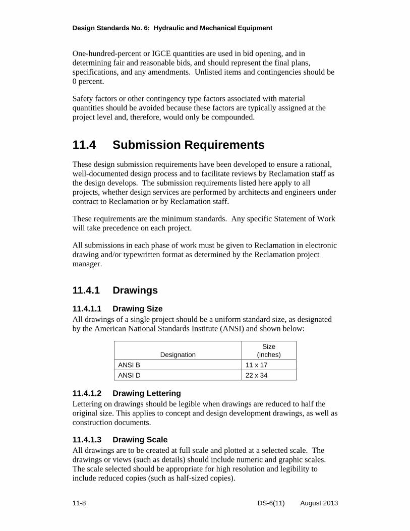
11.4.1.1 Drawing Size All drawings of a single project should be a uniform standard size, as designated by the American National Standards Institute (ANSI) and shown below:
Size Designation (inches)
ANSI B 11 x 17
ANSI D 22 x 34
11.4.1.2 Drawing Lettering Lettering on drawings should be legible when drawings are reduced to half the original size. This applies to concept and design development drawings, as well as construction documents.
11.4.1.3 Drawing Scale All drawings are to be created at full scale and plotted at a selected scale. The drawings or views (such as details) should include numeric and graphic scales. The scale selected should be appropriate for high resolution and legibility to include reduced copies (such as half-sized copies).
11-8 DS-6(11) August 2013

Chapter 11: Heating, Ventilation, and Air-Conditioning Systems
11.4.1.4 Computer-Aided Design Standards National Computer-Aided Design (CAD) standards should be followed for all CAD drawings. Reclamation-specific CAD standards are available through the Reclamation project manager.
11.5 Design Criteria
11.5.1 Outdoor Design Criteria
Outdoor air design criteria should be based on weather data tabulated in the latest edition of the ASHRAE Handbook - Fundamentals. Winter design conditions should be based on the 99.6-percent column dry bulb temperature. Summer design conditions for sensible heat load calculations should be based on the 0.4-percent dry bulb temperature with its mean coincident wet bulb temperature. Design conditions for summer ventilation load calculations should be based on the 0.4-percent dewpoint with its mean coincident dry bulb temperature.
Where HVAC systems are used for equipment protection, the winter and summer design temperatures should be based on the ASHRAE weather data “n Year Return Values of Extreme Dry Bulb” for n=50.
11.5.2 Indoor Design Criteria
11.5.2.1 Indoor Design Temperatures and Relative Humidity For occupied spaces, indoor design temperatures should be 75 degrees Fahrenheit (°F) and 68 °F, respectively, for cooling and heating. In unoccupied spaces, indoor design temperatures should be 85 °F and 55 °F, respectively, for cooling and heating. Indoor design temperatures in spaces that contain equipment should be maintained within the manufacturer-recommended temperatures.
Space Minimum
(ºF) Maximum
(ºF)
Oil storage and transfer rooms 45 80
Toilets and janitor rooms 65 85
Paint storage rooms 45 80
Paint booths 65 80
Welding rooms 65 80
Battery rooms 50 80
Chlorine storage indoors 45 90
Generator room level 45 80
Generator room ceiling level 120
DS-6(11) August 2013 11-9

Design Standards No. 6: Hydraulic and Mechanical Equipment
Space Minimum
(ºF) Maximum
(ºF)
Pipe galleries 45 80
Electrical galleries 45 104
Visitor facilities 68 80
Control rooms 68 80
Computer rooms 72 78
Uninterruptable power supply (UPS) rooms
65 90
Lunch rooms 68 80
Offices 68 80
HVAC machinery 55 90
Air compressor and pump rooms 45 90
11.5.2.2 Limitation of Supply Air Temperature Supply air should be no less than 55 °F dry bulb to prevent condensation on the duct surfaces.
11.5.2.3 Indoor Air Quality The outdoor air ventilation rates of ASHRAE Standard 62.1 are the minimum acceptable in Reclamation buildings. Where occupancy requirements are likely to generate high levels of airborne particles, special air filtration should be provided on the return air system, or dedicated and localized exhaust systems should be used to contain airborne particulates.
Air filtration should be provided in every air-handling system. In occupied spaces, the AHUs should have a disposable prefilter and a final filter. In unoccupied spaces, the AHUs should have a disposable prefilter. The filter media should be rated in accordance with ASHRAE Standard 52.2. The prefilters should have a Minimum Efficiency Reporting Value (MERV) of 8, and the final filters should have a MERV of 13. Filter racks should be designed to minimize the bypass of air around the filter media with a maximum bypass leakage of 0.5 percent.
The placement and location of outdoor air intakes are critical to the safety of the occupants inside a building and should be in compliance with ASHRAE Standard 62.1, which provides minimum separation distances between ventilation air intakes and other building features.
11.5.2.4 Occupancy Levels Refer to architectural drawings for space utilization schedules. Sensible and latent loads per person should be based on the latest edition of the ASHRAE Handbook - Fundamentals.
11-10 DS-6(11) August 2013

Chapter 11: Heating, Ventilation, and Air-Conditioning Systems
For dining areas, auditoriums, and other high occupancy spaces, occupancy loads should represent the number of seats available. Areas such as storage rooms or mechanical rooms do not have occupancy loads.
For plant areas, occupancy levels should be based on the anticipated maintenance personnel present in each area.
11.5.2.5 Equipment Power Densities Internal heat gain from all equipment (electrical, gas, or steam) should be considered. The rates of heat gain from equipment should be based on the latest edition of the ASHRAE Handbook - Fundamentals or manufacturers’ data. For printers and personal computers, 80-percent diversity should be considered.
The internal heat gains from equipment should be coordinated with the project electrical engineer, and based on, the electrical load analysis and the estimated receptacle demand load.
11.5.2.6 Lighting Power Densities The internal heat gains from lighting systems should be coordinated with the project electrical engineer, and based on, the electrical load analysis.
11.5.2.7 Acoustical Design Criteria All mechanical systems should be designed to satisfy Occupational Safety and Health Administration (OSHA) guidelines.
11.5.3 HVAC Loads Calculations
Heating and cooling loads should be calculated in accordance with the procedures outlined in the latest edition of ASHRAE Handbook - Fundamentals. Design heat transmission coefficients used for cooling and heating loads should be obtained from the architect and should reflect the actual materials to be specified. Heat transmission coefficients from ASHRAE Standard 90.1 should be used when actual data are not available.
The HVAC load calculations should be performed with a computer-based program using the latest ASHRAE Handbook - Fundamentals Heat Balance Method, Radiant Time Series Method, or Transfer Function Method, developed for the hourly analysis of heating and cooling loads in commercial buildings.
The program should be capable of calculating each zone’s peak heating and cooling load, as well as the whole building “block” loads. The program should calculate, at a minimum:
Solar gains through fenestration
Internal gains from occupants, including latent heat for cooling purposes
DS-6(11) August 2013 11-11

Design Standards No. 6: Hydraulic and Mechanical Equipment
Internal gains from lighting and equipment
Outside air loads (sensible and latent) from ventilation and infiltration
Heat gains or losses through fenestration, walls, floors, and roofs
The heating load calculations should be done without credit for occupants and internal gains.
The HVAC load calculations report should include all input and output used in the heating and cooling calculation program, as well as zone peak heating and cooling loads results, whole building “block” loads, AHU coil selections, and psychrometric process charts.
11.5.3.1 Energy Calculations A building energy analysis should be performed to demonstrate that the building design meets or exceeds the energy performance goals established for the project.
The building energy analysis should be performed using ASHRAE Standard 90.1, Energy Cost Budget methodology, or appendix G of that standard. In addition, the building energy analysis should demonstrate compliance with the latest editions of ASHRAE Standard 90.1 and 10 CFR 434, Energy Code For New Federal Commercial And Multi-Family High Rise Residential Buildings. The analysis should be included in each design submission.
The analysis should be based on actual parameters and values found in the proposed building design, not simply on defaults assigned by the simulation program.
The analysis should be performed using a computer-based simulation program for the analysis of energy in buildings. Simulation programs should be capable of simulating the following:
8,760-hours per year, hourly variations in occupancy
Lighting power, miscellaneous equipment power
Thermostat setpoints, and HVAC system operation defined separately for each day of the week and holidays
Thermal mass effects
The number of required HVAC zones
Part-load performance curves for mechanical equipment, capacity and efficiency correction curves for mechanical equipment
Air-side and water-side economizers
Temperature controls.
11-12 DS-6(11) August 2013

Chapter 11: Heating, Ventilation, and Air-Conditioning Systems
The building energy analysis report should include all input and outputs used in the simulation program, including:
Established energy goals for the project Detailed descriptions of the budget and proposed building models Actual local utility rates Descriptions of any and all energy conservation measures An analysis of results with final conclusions and recommendations
11.5.3.2 Load Calculations and Weather Conditions Reclamation projects are seldom constructed at one of the locations listed in the ASHRAE weather data; however, the data can be adjusted to approximate local conditions. Designers should be aware of the intended applications and operational characteristics of the plant (e.g., summer and/or winter operation, criticality of plant down time, etc.).
11.5.4 HVAC System Controls
11.5.4.1 General Considerations Reclamation plants are located in remote areas where a high degree of technical service may not be available. Systems should be designed simply to ensure reliability and facilitate repairs. Tight control schemes are generally not necessary and should be avoided, except where equipment operation is dependent on such control (i.e. computer rooms or data centers). Offices should be maintained at normal comfort levels. Plant temperatures are usually allowed to fluctuate between the normal low and high temperature range. Office buildings, in general, should be provided with a programmable Building Automation System (BAS) controlled by a personal computer based operator’s workstation.
11.5.4.2 Energy Management and Conservation The BAS should have the capability to allow building staff to measure energy consumption and monitor performance, which is critical to the overall success of the system.
Energy management measurements should be totalized and trended in both instantaneous and time-based numbers for chillers, boilers, AHUs, and pumps. Energy monitoring data should be automatically converted to standard database and spreadsheet format and transmitted to a designated workstation. Energy points are points that are monitored to ensure compliance with ASHRAE Standard 90.1 and DOI requirements.
11.5.4.2.1 Energy Recovery Most Reclamation plants are designed for unmanned operation; therefore, the primary HVAC objective is equipment protection. However, every design should be evaluated for opportunities to save or recover energy.
DS-6(11) August 2013 11-13

Design Standards No. 6: Hydraulic and Mechanical Equipment
11.5.4.2.2 Free Cooling Where outdoor winter design temperatures are below 35 ºF, an economizer should be considered to provide significant energy savings. Refer to ASHRAE Standard 90.1 for further guidance.
11.5.4.2.3 Freeze Protection Provide freeze-protection, low-limit thermostats or sensors on outside air intake openings or adjacent to water bearing equipment. If necessary, the thermostat should open an automatically controlled drain valve to drain water from the system.
11.5.4.2.4 High-Limit Thermostats Provide a high-limit thermostat or sensor downstream of electric heating coils to de-energize the coils if discharge temperature is too high (135 to 165 ºF).
11.5.4.2.5 Step and Proportional Controllers The output of electric heating coils should be controlled through multistage step controllers or proportional controllers. Provide a differential pressure switch or an airflow switch to prevent energizing the coil if airflow is not verified or to de-energize the coil if the airflow fails to maintain the minimum velocity through the coil.
11.5.4.2.6 Integral Controls Factory assembled controllers should be used, where available, to reduce design time and facilitate installation of the HVAC equipment, especially when a single HVAC unit or multiple identical HVAC units by the same manufacturer are being installed.
11.5.4.2.7 Remote Indicating Panels In locations where life safety is dependent on ventilation, remote indicating panels should be provided. The indicating panel should monitor the operating status of the main HVAC system and equipment and be independent of the main HVAC system control panel. In addition, the panel should include sufficient indicating lights to identify specific equipment failures, warn maintenance personnel when equipment servicing is required, assist maintenance personnel in isolating problems, and warn operators of an HVAC system failure. Where the plant is monitored from a remote control center, the indicating panel contact should be interfaced with the Supervisory Control and Data Acquisition system (SCADA).
Auxiliary equipment, such as air transfer and exhaust fans, should be monitored locally by installing indicating lights on their motor starter panels as discussed under the specific system requirements elsewhere in this manual.
11.5.4.3 Heating The electric heater in each main air-conditioning unit should be sized to handle the space loads, as well as heating of the minimum quantity of outdoor air required by the space. The capacity of the heater should be divided into
11-14 DS-6(11) August 2013

Chapter 11: Heating, Ventilation, and Air-Conditioning Systems
individual stages that will each heat the volume of mixed air between 5 ºF and 10 ºF. The heater should be automatically controlled through a step controller or proportional controller to stage the heater from no load to full load. The actual number of steps depends on the occupancy and equipment available.
11.5.4.4 Cooling When free cooling cannot maintain the space temperature below the high temperature limit, the cooling system should be energized, and the outdoor air damper should be returned to the minimum position.
11.5.4.5 Fan Economizer Systems Many plants are provided with superstructure ventilation/economizer systems that consist of multiple wall-mounted air-intake louver and control-damper assemblies and exhaust-damper and fan assemblies. These systems are automatically controlled by remote bulb controllers. In plants that are air-conditioned by refrigeration equipment, the controls should signal the economizer exhaust fans to de-energize and the intake and exhaust dampers to close when the plant controls call for refrigeration cooling.
11.6 Building Types
11.6.1 Office Buildings
11.6.1.1 Design Considerations The primary objectives of office building air-conditioning systems are to ensure human comfort, health, and safety. HVAC equipment should satisfy sanitary, hygienic, industrial, fire, and emergency requirements and should comply with the building standards listed herein for construction, installation, performance, energy conservation, and safety.
11.6.1.2 Building Automation System Office buildings should be equipped with a BAS that has the capability of controlling all HVAC systems. The system infrastructure should be BACnet based and be open-protocol. No proprietary systems should be allowed. The interface with the BAS system should be through a single operator’s workstation that consists of a desktop computer or laptop capable of operating the system without delay. The operator’s interface should include interactive graphics that enable the modification of data points. Electronic operation and maintenance manuals should be included with, and incorporated into, the BAS.
11.6.1.3 Building Pressurization Calculations should be provided that show the minimum outdoor airflow rate required for pressurization. The following areas should be kept under negative pressure relative to surrounding building areas: showers, locker rooms, custodial
DS-6(11) August 2013 11-15
Design Standards No. 6: Hydraulic and Mechanical Equipment
spaces, battery charging rooms, kitchens, and dining areas. Air can be returned from the dining area space; however, the air from all other spaces should be exhausted directly to the outdoors.
11.6.1.4 Indoor Air Quality Outdoor air ventilation should be provided as required by ASHRAE Standard 62.1. Controls should be provided to modulate outdoor airflow based on occupancy.
11.6.1.5 Thermostatic Zoning Design Criteria Interior thermostatic control zones should not exceed 1,500 square feet per zone for open office areas, or a maximum of three offices per zone for closed office areas.
Perimeter thermostatic control zones should be no more than 15 feet from an outdoor wall along a common exposure. Corner offices should be dedicated zones.
If a building program shows that an office building should have an open plan layout, or if the program does not state a preference, it may be assumed that up to 40 percent of the floor plan will be occupied by closed offices at some point in the future.
11.6.2 Power Plants, Pumping Plants, and Water Treatment Plants
11.6.2.1 Design Considerations The primary objectives of air-conditioning systems within plants are to ensure human health and safety, as well as equipment protection. HVAC equipment should satisfy industrial, fire, and emergency requirements and should comply with the building standards listed herein for construction, installation, performance, energy conservation, and safety.
Plants should be cooled using transfer air methods as long as the required maximum temperatures can be met using less than 30 air changes per hour. When conditioned air is required, the following options should be considered in the order given: (1) AHU with cold water coils using site water (generally limited to water temperatures below 65 ºF); (2) direct evaporative coolers; (3) indirect/direct evaporative coolers; (4) direct expansion coils, and (5) chilled water.
11.6.2.2 Special Environmental Conditions Some plant rooms such as control, computer, and UPS rooms; lunch rooms; and office spaces require tighter environmental control to avoid wide temperature fluctuations, to ensure proper operation of equipment, and to provide comfort conditions for sedentary personnel. Furthermore, since these rooms may be
11-16 DS-6(11) August 2013

Chapter 11: Heating, Ventilation, and Air-Conditioning Systems
occupied when the plant HVAC system is shut down, these HVAC systems and controls should be completely independent of the plant HVAC system. In most instances, these spaces require similar environmental conditions, and a single centrally located HVAC system may be used.
11.6.2.3 Redundant Systems or Equipment When inadvertent temperature shutdown of the main units cannot be tolerated, redundancy should be considered. Redundancy may be complete or partial.
The controls for redundant systems or equipment should include automatic and manual switching to equalize wear on all components.
Designers should contact project personnel to discuss the criticality of maintaining the plant online under extreme temperature conditions and to determine the degree of redundancy that is necessary or required.
11.6.2.4 Basic HVAC Scheme 11.6.2.4.1 Heating Systems Most plants are constructed at remote locations where natural gas is not available. Propane and fuel oil are not used for heating applications due to storage, the below grade location of mechanical rooms, and the logistics of frequent refilling at remote locations. Primary heating is usually provided by electric duct heaters or unit heaters.
Off-the-shelf electric heaters should be avoided in spaces containing explosive gases or atmospheres. Heaters for these spaces must comply with NFPA Code 70 (also known as the National Electric Code) explosive-proof construction requirements.
Many Reclamation plants operate throughout the year; therefore, these plants are capable of generating recoverable heat. When economically feasible (simple payback of less than 7 years), the heat generated by electric motors or generators should be recovered and used to temper cooler air.
11.6.2.4.2 Cooling Systems When possible, cooling should begin with 100-percent outdoor air. In plants having generators and/or motors rated over 1,500 kilowatts, the units are normally furnished with integral water-cooled systems. While such systems will remove the vast majority of heat load to the space, a small amount will still be radiated and must be accounted for. The plant air-conditioning units should also handle all other loads within the plant.
When the main motor or generator units are air cooled, cooling air must be provided to the space by air transfer ventilation, evaporative cooling units, water coil cooling units, or refrigeration equipment. Frequently, cooling water is available directly from reservoirs, penstocks, or discharge lines.
DS-6(11) August 2013 11-17

Design Standards No. 6: Hydraulic and Mechanical Equipment
11.6.2.4.3 Location of Air Intakes and Exhaust Openings Outdoor air louvers should be located opposite major heat sources such as electrical control equipment and transformers. The bottom of the intake louvers should be located a minimum of 2 feet from ground level. Locate louvers away from air polluting sources such as engine generators and building exhaust air openings. Avoid locations near light fixtures that tend to attract insects at night. Allow 50 to 75 feet of space between air intakes and exhaust openings.
In areas where noise generated by the plant is regulated by locally established noise criteria, the location and design of intake openings should be given special consideration. Sound insulation or attenuating equipment may be necessary to prevent unacceptable plant or air-conditioning system noise from reflecting through the air intakes into the yard and surrounding area.
11.6.2.4.4 Substructure Heating, Cooling, and Ventilation The below-grade portions (substructures) of a plant should be heated and cooled to maintain minimum and maximum temperatures for equipment protection, to prevent freezing, and to ensure personnel comfort. The preferred method for ventilating oil storage, paint, battery, toilet, sumps, janitor, welding, or chemical storage rooms is through the use of transfer air from other plant spaces. However, air from these rooms is considered contaminated and should be directly exhausted outdoors away from air intake louvers.
11.6.2.4.5 Superstructure Heating, Cooling, and Ventilation In general, the above-grade portions (superstructures) of a plant should not be cooled or heated, except where temperatures should be maintained to protect equipment from freezing or excessively high temperatures and condensation of water on metalwork.
11.6.3 Prefabricated Control Buildings
11.6.3.1 General Heating, cooling, and ventilation devices for prefabricated control buildings are typically designed and provided by the building manufacturer. Cooling methods (e.g., transfer air cooling or evaporative cooling) and space constraints (temperature, humidity, etc.) are defined and given as criteria to the building manufacturer.
11.6.4 Confined Spaces: Gate Chambers, Tunnels, Shafts, Vaults, and Underground Structures
11.6.4.1 General When confined spaces, such as gate chambers, outlet pipe tunnels or access shafts, valve vaults and penstock tunnels, and connecting adits are occupied,
11-18 DS-6(11) August 2013

Chapter 11: Heating, Ventilation, and Air-Conditioning Systems
continuous mechanical ventilating systems must be provided. The ventilating system may be either a supply or exhaust type and may be fixed or temporary. Fixed systems are permanently installed and are intended to operate only for inspection activities.
Spaces with explosive gases must be continuously ventilated at all times regardless of whether the spaces are occupied.
11.6.4.2 Air Quality Standards Acceptable air quality must be maintained in tunnels and gate chambers at all times when the spaces are occupied.
11.6.4.2.1 Airflow Requirements The following criteria are provided to assist in determining the minimum ventilating system airflow requirements. The actual design airflow must satisfy all the criteria; therefore, the criteria that yield the highest airflow should be used to size the fan and other ventilating system equipment.
11.6.4.2.2 Fixed Ventilating System Airflow Design Criteria Fixed ventilating systems are normally designed for permanent installation and are intended for intermittent operation during inspection of tunnels, gate chambers, gates, gate controls, and other equipment contained in these areas. These systems are not designed or intended to provide adequate ventilation during maintenance or construction activities.
Reclamation projects should be designed to comply with Reclamation Safety and Health Standards or OSHA requirements, whichever is more stringent.
11.6.4.2.3 OSHA Minimum Ventilation The absolute minimum volume of air to be supplied to the gate chamber or confined space should be that required by OSHA 29 CFR, 1926.800. A minimum of three persons should be assumed to occupy the space simultaneously.
Maintain a minimum airflow velocity as defined by OSHA 29 CFR, 1926.800.
11.6.5 Enclosed Stairwells and Elevator Shafts
11.6.5.1 Ventilation Enclosed stairwells and elevator shafts should be ventilated continuously. Air is usually transferred into the stairwell from the lower levels of the plants. Air flows up the stairwell to the highest level and exits back into the superstructure. Air from elevator shafts should be exhausted outdoors.
Ventilation of plant stairwells and elevator shafts should be provided by wall mounted propeller fans located at the bottom of the stairs.
DS-6(11) August 2013 11-19
Design Standards No. 6: Hydraulic and Mechanical Equipment
11.6.5.2 Pressurization Elevator shafts are not usually provided with pressurization systems; therefore, the following discussion pertains to enclosed stairwells only.
When required by code, stairwells should be provided with a dedicated pressurization system that is independent of the main plant HVAC system. The fan should be capable of pressurizing the stairwell with 100-percent outdoor air to provide a refuge zone for personnel and to allow safe plant evacuation. The system should be capable of minimizing smoke penetration when a limited number of doors are opened during evacuation.
11.6.5.2.1 Design The stairwell pressure system should be designed in accordance with the requirements and procedures of NFPA 92 and ASHRAE Design of Smoke Management Systems. A typical design includes a fan, outdoor air louver, control damper and operator, relief or bypass dampers, ductwork, and controls.
11.7 Smoke Exhaust
Provide smoke control systems unless exempted by the International Building Code. These systems should be installed to comply with the International Fire Code and the National Fire Protection Agency (NFPA) standards.
11.8 Service Space Requirements
Space requirements of mechanical and electrical equipment rooms should be based on the layout of required equipment drawn to scale within each room.
During preparation of concept designs, approximately 4 percent of each floor’s gross floor area should be allotted for air-handling equipment. Where additional equipment is required, additional space on that floor should be provided as needed.
A minimum of 1 percent of the building’s gross floor area should be provided for the central heating and cooling plant (location to be agreed upon during preparation of concept submission).
11.8.1 Service Access
Space should be provided around all HVAC system equipment as recommended by the manufacturer and in compliance with local code requirements for routine maintenance. Access doors or panels should be provided in ventilation equipment, ductwork, and plenums as required for inspection and cleaning. Equipment access doors or panels should be readily operable and sized to allow
11-20 DS-6(11) August 2013
Chapter 11: Heating, Ventilation, and Air-Conditioning Systems
full access. Large central equipment should be situated to facilitate its replacement. The HVAC design engineer should be aware of the necessity to provide for the replacement of major equipment over the life of the building and should ensure that provisions are made to remove and replace, without damage to the structure, the largest and heaviest component that cannot be further broken down.
In addition, adequate methods of access should be included for items such as chillers, boilers, AHUs, heat exchangers, cooling towers, reheat coils, Variable Air Volume (VAV) terminals, pumps, water heaters, and all devices that have maintenance service requirements.
To facilitate equipment access, maintenance, removal, and replacement, a freight elevator stop should be provided to serve each floor that houses HVAC systems and equipment.
Where stairs are required, they should allow for safe transport of equipment and components. Ship’s ladders are not permitted for access and maintenance of any equipment.
11.8.2 Roof-Mounted Equipment
If possible, avoid the placement of mechanical equipment, except for exhaust fans, on the roof of the building. Provide access to roof-mounted equipment with stairs, not ship’s ladders.
11.8.3 Equipment Pads
Equipment pads should be 6 inches thick and at least 6 inches wider on all sides than the equipment they support.
11.9 Specific Space Criteria
11.9.1 Mechanical Rooms
All mechanical rooms should be mechanically ventilated to maintain room space conditions as indicated in ASHRAE Standard 62.1. Mechanical rooms should have floor drains close to the equipment they serve to reduce water streaks or drain lines extending into aisles. Mechanical rooms should not be used as return air, outdoor air, or mixing plenums.
DS-6(11) August 2013 11-21

Design Standards No. 6: Hydraulic and Mechanical Equipment
11.9.2 Chiller Equipment Rooms
All rooms for refrigerant units should be constructed and equipped to comply with the International Mechanical Code (IMC). Chiller staging controls should be capable of Display Data Channel (DDC) communication to the central BAS.
11.9.3 Electrical Equipment Rooms
No piping or ductwork is permitted in electrical, control, Information Technology, Telecom, UPS, and similar-type rooms, except for fire sprinkler piping and ducts serving the space. Sprinkler piping lines should not be located directly above any electrical equipment.
11.9.4 Fire Pump Rooms
No water lines or ductwork are permitted in fire pump rooms, except for fire sprinkler piping and ducts serving the space. Sprinkler piping lines should not be located directly above any electrical equipment.
11.9.5 Communications Closets
Communications closets should be cooled in accordance with the requirements of EIA/TIA Standard 569, “Commercial Building Standard for Telecommunication Pathways and Spaces.” Closets that house critical communications components should be provided with dedicated air-conditioning systems connected to the emergency power distribution system.
11.9.6 Elevator Machine Rooms
A dedicated heating and/or cooling system should be provided to maintain room conditions required by equipment specifications. If the building is fully sprinklered with automatic sprinklers, hoist way venting is not required.
11.9.7 Emergency Generator Rooms
The environmental systems should meet the requirements of NFPA Standard 110, “Emergency and Standby Power Systems,” as well as the combustion air requirements of the equipment. Rooms should be ventilated sufficiently to remove heat gain from equipment operation. The supply and exhaust louvers should be located to prevent short circuiting. Generator exhaust should be carried
11-22 DS-6(11) August 2013
Chapter 11: Heating, Ventilation, and Air-Conditioning Systems
up to roof level in a flue or exhausted according to the generator manufacturer’s installation guidelines. Horizontal exhaust through the building wall should be avoided.
11.9.8 UPS Battery Rooms
The battery room should be ventilated/exhausted directly to the outdoors as required by the IMC and at a rate sufficient to prevent hazardous buildup of hydrogen and ozone.
11.9.9 Loading Docks
The entrances and exits at loading docks and service entrances should be maintained at negative pressure relative to the rest of the building and have the ability to reduce infiltration and outdoor debris.
11.10 HVAC Components
11.10.1 Air-Handling Units
All AHUs, including dedicated outdoor air ventilation units, dedicated perimeter pressurization units, floor-by-floor AHUs, and AHUs serving special areas, should be sized so that they do not exceed 25,000 cubic feet per minute.
Smaller units are encouraged to facilitate flexible zone control, particularly for spaces that involve off-hour or high-load operating conditions. To the extent possible, “plug-n-play” AHU configurations should be considered, which will facilitate easy adaptations to space-load changes in the future.
11.10.1.1 Coils Individual finned tube coils should generally be between six and eight rows with at least 12 fins per inch to ensure that the coils can be effectively and efficiently cleaned. Dehumidifying coils should be selected for no more than negligible water droplet carryover beyond the drain pan at design conditions. All hot water heating and chilled water cooling coils should be copper tube and copper finned materials. Equipment and other obstructions in the air stream should be located sufficiently downstream of the coil so that it will not come in contact with the water droplet carryover. Cooling coils should be selected at or below a face velocity of 500 feet per minute (ft/min) to minimize moisture carryover. Heating coils should be selected at or below a face velocity of 375 ft/min.
11.10.1.2 Drains and Drain Pans Drain pans should be made of stainless steel, insulated, and adequately sloped and trapped to ensure proper drainage.
DS-6(11) August 2013 11-23

Design Standards No. 6: Hydraulic and Mechanical Equipment
11.10.1.3 Filter Sections Filters should be sized at 500-ft/min maximum face velocity. Filter media should be fabricated so that fibrous shedding does not exceed levels prescribed by ASHRAE Standard 52.2. The filter housing and all air-handling components downstream should not be internally lined with fibrous insulation. The filter change-out pressure drop, not the initial clean filter rating, should be used to determine fan pressure requirements. Differential pressure gauges and sensors should be placed across each filter bank to allow quick and accurate assessment of filter dust loading as reflected by air-pressure loss through the filter, and sensors should be connected to the building’s automation system.
11.10.1.4 UVC Emitters/Lamps Ultraviolet light in the C band (UVC) emitters/lamps should be incorporated downstream of all cooling coils in a AHU and above all drain pans to control airborne and surface microbial growth and transfer. Applied fixtures/lamps should be specifically manufactured for this purpose. Safety interlocks/features should be provided to limit hazard to operating staff.
11.10.1.5 Access Doors Access doors should be provided at AHUs downstream of each coil, upstream of each filter section, and adjacent to each drain pan and fan section. Access doors should be of sufficient size to allow personnel to enter the unit to inspect and service all portions of the equipment components.
11.10.1.6 Plenum Boxes AHUs should be provided with plenum boxes where relief air is discharged from the AHU. Plenum boxes may also be used on the return side of the unit in lieu of a mixing box. Airflow control dampers should be mounted on the ductwork connecting to the plenum box.
11.10.1.7 Mixing Boxes AHUs should be provided with mixing boxes where relief air is discharged from the AHU. Mixing boxes may also be used on the return side of the unit in lieu of a plenum box. Airflow control dampers should be mounted within the mixing box or on the ductwork connecting to the mixing box.
11.10.2 Air Distribution
Ductwork should be designed in accordance with the ASHRAE Handbook - Fundamentals and constructed in accordance with the ASHRAE HVAC Systems and Equipment Handbook and the SMACNA Design Manuals. Supply, return, and exhaust air ducts should be designed and constructed to allow no more than 3 percent leakage of total airflow in systems up to 3.0 inches water gauge (w.g.). In systems from 3.0 inches w.g. through 10.0 inches w.g., ducts should be designed and constructed to limit leakage to 0.5 percent of the total airflow. All
11-24 DS-6(11) August 2013

Chapter 11: Heating, Ventilation, and Air-Conditioning Systems
ductwork joints and all connections to air handling and air distribution devices should be sealed with mastic including all supply and return ducts, any ceiling plenums used as ducts, and all exhaust ducts.
11.10.2.1 Air Delivery Devices Terminal ceiling diffusers or booted-plenum slots should be specifically designed for VAV air distribution. Booted plenum slots should not be longer than 1.2 meters (4 feet) unless more than one source of supply is provided. “Dumping” action at reduced air volume and sound power levels at maximum delivery should be minimized. For VAV systems, the diffuser spacing selection should not be based on the maximum or design air volumes. It should be based on the air volume range the system is expected to operate at most of the time.
The designer should consider the expected variation in range in the outlet air volume to ensure that the Air Diffusion Performance Index (ADPI) values remain above a specified minimum. This is achieved by low temperature variation, effective air mixing, and no objectionable drafts in the occupied space (typically 6 inches to 6 feet above the floor). Adequate ventilation requires that the selected diffusers effectively mix the total air in the room with the supplied conditioned air, which is assumed to contain adequate ventilation air.
11.10.2.2 VAV Terminals VAV terminals should be pressure-independent type units. Air leakage from the casing of a VAV box/terminal should not exceed 2 percent of its rated capacity.
11.10.2.3 Ductwork 11.10.2.3.1 Sizing Supply and return ductwork should be sized using the equal friction method using a maximum of 0.1 inch w.g. per 100 feet of ductwork.
11.10.2.3.2 Construction Ductwork should be fabricated from galvanized steel unless otherwise required by the IMC. Flex duct may be used for low-pressure ductwork downstream of the terminal box in office spaces. Flex duct runs should not exceed 6 feet or contain more than two bends. Joint sealing tape for all connections should be of reinforced fiberglass backed material with field applied mastic.
11.10.2.4 Louvers 11.10.2.4.1 Area and Velocity 11.10.2.4.1.1 Outdoor Air Velocity.—To estimate the required wall openings, stationary louvers should be sized to prevent the entrainment of rain or snow.
11.10.2.4.1.2 Exhaust Air Free Area.—To reduce noise and minimize pressure loss, the maximum pressure drop should not exceed 0.15 inches w.g.
DS-6(11) August 2013 11-25
Design Standards No. 6: Hydraulic and Mechanical Equipment
11.10.2.4.1.3 Location.—Locate louvers a minimum of 2 feet above ground level to reduce clogging by debris.
11.10.2.4.2 Construction When louvers are to be installed near ground level, or where they may be subject to vandalism, consider whether project conditions may require bullet-resistant construction.
11.10.2.4.3 Screens Provide galvanized or stainless steel insect screens on all louvers. The pressure loss due to the reduced free area of the screen is not included in the louver static pressure and should be added to the system losses.
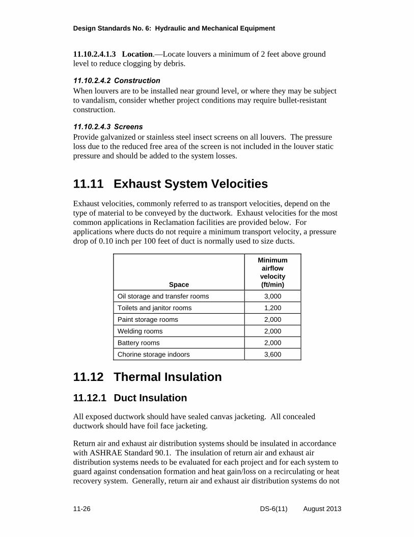
11.11 Exhaust System Velocities
Exhaust velocities, commonly referred to as transport velocities, depend on the type of material to be conveyed by the ductwork. Exhaust velocities for the most common applications in Reclamation facilities are provided below. For applications where ducts do not require a minimum transport velocity, a pressure drop of 0.10 inch per 100 feet of duct is normally used to size ducts.
Space
Minimum airflow velocity (ft/min)
Oil storage and transfer rooms 3,000
Toilets and janitor rooms 1,200
Paint storage rooms 2,000
Welding rooms 2,000
Battery rooms 2,000
Chorine storage indoors 3,600
11.12 Thermal Insulation
11.12.1 Duct Insulation
All exposed ductwork should have sealed canvas jacketing. All concealed ductwork should have foil face jacketing.
Return air and exhaust air distribution systems should be insulated in accordance with ASHRAE Standard 90.1. The insulation of return air and exhaust air distribution systems needs to be evaluated for each project and for each system to guard against condensation formation and heat gain/loss on a recirculating or heat recovery system. Generally, return air and exhaust air distribution systems do not
11-26 DS-6(11) August 2013

Chapter 11: Heating, Ventilation, and Air-Conditioning Systems
require insulation if they are located in a ceiling plenum or mechanical room used as a return air plenum. All equipment, heat exchangers, converters, and pumps should be insulated as per ASHRAE Standard 90.1.
11.12.2 Piping Insulation
All piping systems should be insulated in accordance with ASHRAE Standard 90.1. All piping systems with surface temperatures below the average dew point temperature of the indoor ambient air and where condensate drip will cause damage or create a hazard should be insulated with a vapor barrier to prevent condensation formation regardless of whether piping is concealed or exposed. Chilled water piping systems should be insulated with nonpermeable insulation (of perm rating 0.00), such as cellular glass. All exposed and concealed piping should have polyvinyl chloride jacketing.
11.12.3 Equipment Insulation
All equipment including AHUs, chilled and hot water pumps, and heat exchangers should be insulated in accordance with ASHRAE Standard 90.1. All HVAC pumps should have jacketing.
11.13 Vibration Isolation, Acoustical Isolation, and Seismic Design for Mechanical Systems
11.13.1 Noise and Vibration Isolation
Refer to and incorporate the basic design techniques as described in the ASHRAE Handbook - HVAC Applications. Isolate all moving equipment in the building.
11.13.2 Mechanical Shafts and Chases
Any piping and ductwork should be isolated as it enters the shaft to prevent increased vibration to the building structure. All openings for ducts and piping should be sealed. Shafts dedicated to gas piping should be ventilated.
11.13.3 Isolators
Isolators should be specified by type and by deflection, not by isolation efficiency. See ASHRAE Guide for Selection of Vibration Isolators and ASHRAE Handbook – HVAC Applications for types and minimum deflections.
DS-6(11) August 2013 11-27

Design Standards No. 6: Hydraulic and Mechanical Equipment
11.13.4 Concrete Inertia Bases
Inertia bases should be provided for reciprocating and centrifugal chillers, all base-mounted pumps, axial fans above 300 revolutions per minute, and centrifugal fans above 50 horsepower.
11.13.5 Ductwork
Reduce fan-generated noise immediately outside of any mechanical room wall by acoustically coating or wrapping the duct. The ductwork design should appropriately consider and address airborne equipment noise, equipment vibration, ductborne fan noise, duct breakout noise, airflow generated noise, and ductborne crosstalk noise. All ductwork connections to equipment having motors or rotating components should be made with a 6-inch length of flexible connecters. All ductwork within the mechanical room should be supported with isolation hangers.
11.13.6 Piping Hangers and Isolation
Isolation hangers should be used for all piping in mechanical rooms and adjacent spaces, up to a 50-foot distance from vibrating equipment. The pipe hanger closest to the equipment should have the same deflection characteristics as the equipment isolators. Other hangers should be spring hangers with 0.75-inch deflection. Positioning hangers should be specified for all piping 8 inches and larger throughout the building. Spring and rubber isolators are recommended for piping 2 inches and larger hung below noise sensitive spaces.
Floor supports for piping may be designed with spring mounts or rubber pad mounts. For pipes subject to large amounts of thermal movement, plates of Teflon or graphite should be installed above the isolator to permit horizontal sliding.
Anchors and guides for vertical pipe risers should usually be attached rigidly to the structure to control pipe movement. Flexible pipe connectors should be designed into the piping before it reaches the riser.
11.13.7 Seismic Criteria
Obtain the following values from structural engineering drawings and specifications or from ASCE 7-10. Use the site class, assigned seismic user group, building category, component importance factor, component response modification factor, component amplification factor, short period response acceleration factor, and one second period response acceleration factor to determine the extent of seismic restraint that is required by the project.
11-28 DS-6(11) August 2013

Chapter 11: Heating, Ventilation, and Air-Conditioning Systems
11.13.8 Piping Supports
The hanger and support schedule should include manufacturer’s number, type, and location. Spring hangers and supports should be provided in all of the mechanical rooms.
11.14 Noise Control in Duct Systems
Duct noise should be in compliance with sound standards set forth in the ASHRAE Handbook - HVAC Applications. Duct noise control should be achieved by controlling air velocity, using sound attenuators, using double wall ductwork with insulation in between, and by not oversizing the terminal units. Duct liners are not permitted for sound attenuation. Terminal units should be selected so that design air volume is approximately three-quarters of the terminal box’s maximum capacity. Volume dampers in terminal units should be located at least 6 feet from the closest diffuser, and the use of grille-mounted balance dampers should be restricted, except for those applications with accessibility problems.
11.15 Meters, Gauges, and Flow Measuring Devices
11.15.1 Thermometers and Gauges
Each piece of mechanical equipment should be provided with the instrumentation or test ports to verify critical parameters such as capacity, pressures, temperatures, and flow rates. The general instrumentation requirements follow.
Thermometers and pressure gauges are required on the suction and discharge of all pumps, chillers, boilers, heat exchangers, cooling coils, heating coils, and cooling towers. To avoid pressure gauge tolerance errors, a single pressure gauge may be installed and valved to sense the pressure differential between the supply and return. For coils with flows less than 10 gallons per minute, provisions should be made for using portable instruments to check temperatures and pressures.
Duct static pressure gauges should be provided for the central AHU air supply fan discharge, branch take-offs of vertical supply risers and at all duct locations at which static pressure readings are being monitored to control the operation of a VAV system.
Differential static pressure gauges should be placed across filters in AHUs and to measure building pressure relative to the outdoors. A temperature gauge is required at the outdoor air intake to each AHU.
DS-6(11) August 2013 11-29
Design Standards No. 6: Hydraulic and Mechanical Equipment
11.16 Testing and Balancing
11.16.1 Startup
Adequately specify testing, adjusting, and balancing of the overall HVAC system(s) in accordance with the design intent. The testing and balancing contractor should have up-to-date certification by the Associated Air Balance Council, the National Environmental Balance Bureau, or the Testing, Adjusting, and Balancing Bureau.
11.16.2 Performance Testing
Specify performance testing of all systems and equipment including chillers, boilers, AHUs, exhaust fans, water heaters, and other systems for part load and full load during summer, winter, spring, and fall seasons according to the schedules specified by the designer.
11.16.3 Ductwork Pressure and Leak Testing
Tests should be conducted at static pressures equal to maximum design pressure of system. Maximum leakage allowable should not exceed 50 percent of that allowed in SMACNA’s HVAC Air Duct Leakage Test Manual.
11.16.4 Piping and Equipment Pressure and Leak Testing
Leak testing should be conducted at static pressures as required by code (or as 120 percent of maximum design working pressure of system where no code requirement exists), with maximum permissible leakage.
11-30 DS-6(11) August 2013

Chapter 11: Heating, Ventilation, and Air-Conditioning Systems
11.17 References
ASHRAE Handbook – HVAC Systems and Equipment. American Society of Heating, Refrigerating, and Air-Conditioning Engineers.
ASHRAE Handbook – HVAC Applications. American Society of Heating, Refrigerating, and Air-Conditioning Engineers.
ASHRAE Handbook - Fundamentals. American Society of Heating, Refrigerating, and Air-Conditioning Engineers.
EIA/TIA Standard 569, “Commercial Building Standard for Telecommunication Pathways and Spaces.”
Executive Order 13423, “Strengthening Federal Environmental, Energy, and Transportation Management.”
Executive Order 13514, “Federal Leadership in Environmental, Energy, and Economic Performance.”
Reclamation Manual Policy, Performing Design and Construction Activities, FAC P03.
Reclamation Safety and Health Standards. U.S. Department of the Interior, Bureau of Reclamation.
DS-6(11) August 2013 11-31


TSC Security Review of Proposed Public Disclosure of Technical Information
Type: Design Standard
Design Standard: Design Standards No. 6 — Hydraulic and Mechanical Equipment
Chapters: 11. Heating, Ventilation, and Air-Conditioning Systems
Brief Description of Information:
Requesting/Sponsoring Organization: Director, Technical Service Center
Program Office: Deputy Commissioner, Operations
Is Information Official Use Only / SENSITIVE? (Y/N) (to be completed by reviewer)
Is Information Official Use Only / RESTRICTED? (Y/N) (to be completed by reviewer) w
(Sensitive or Restricted information shall not be included in a design standard.)
Design Standard Team Leader:
Name(s)/Mail Code(s): J. Michael Weem1486-68410 Signature(s)/Date(s):w7Thw,
/w
Group Manager(s) Appyoving Release:
Name(s)/Mail Code(s): cStw86684191 Signature(s)/Date(s):
Division Security Reviewer(s) Peer Reviewing Approval:
Name(s)/Mail Code(s): David_Hulse/86-68420 Signature(s)/Date(s):
