design study of steady-state 30-tesla liquid-neon-cooled ... · design study of steady-state...
TRANSCRIPT

c
NASA
h m m w n z + 4 c/) 4 z
TECHNICAL NOTE
K
NASA I TN D-8337 11 ,/
DESIGN STUDY OF STEADY-STATE 30-TESLA LIQUID-NEON-COOLED MAGNET
e
George M . Prok and Gerald V. B r o w n
Lewis Research Center Cleuehnd, Ohio 44135
NATIONAL AERONAUTICS AND SPACE ADMINISTRATION WASHINGTON, o. 'i. \ i
x< i
NOVEMBER 1976
https://ntrs.nasa.gov/search.jsp?R=19770004270 2018-05-27T12:12:01+00:00Z

TECH LIBRARY KAFB, NM
I llllllllllllllllllllllllll\lllilnllllll 0334080
19. Security Classif. (of this report) 20. Security Classif. (of this page)
Unclassified ~~
Unclassified
- .
1. Report No. I 2. Government Accession No.
NASA TN D-8337 4. Title and Subtitle
DESIGN STUDY OF STEADY-STATE 30-TESLA LIQUID-NEON-COOLED MAGNET
21. No. o f Pages 22. Price'
37 $4.00
7. Author(s)
George M. Prok and Gerald V. Brown
9. Performing Organization Name and Address
Lewis Research Center National Aeronautics and Space Administration Cleveland, Ohio 44135
National Aeronautics and Space Administration Washington, D. C . 20546
2. Sponsoring Agency Name and Address
5. Supplementary Notes
6. Abstract
5. Report Date
November 1976 6. Performing Organization Code
8. Performing Organization Report No.
~~ ___ E -8780 ~~ -
10. Work Unit No.
506-25
11. Contract or Grant No
13. Type of, Report and Period Covered
Technical Note ~
14. Sponsoring Agency Code
A parametr ic study has produced a design fo r a 30-tesla, liquid-neon-cooled magnet that is capable of continuous operation. Cooled by nonboiling, forced-convection heat t ransfer to liquid neon flowing at 2.8 m /min in a closed, pressurized heat-transfer loop and s t ruc- turally supported by a tapered s t ructural ribbon, the tape-wound coils with a high-purity- aluminum conductor will produce over 30 teslas fo r 1 minute at 850 kilowatts. The magnet will have an inside diameter of 7.5 cent imeters and an outside diameter of 54 centimeters. The minimum curren t density at design field will be 15.7 kA/cm .
3
2
17. Key Words (Suggested by Authorb) )
Cryogenics Magnetic fields Cryogenic magnets Heat t ransfer Magnet coi ls Cooling
18. Distribution Statement
Unclassified - unlimited STAR Category 31
L

DESIGN STUDY OF STEADY-STATE 30-TESIA LIQUID-NEON-COOLED MAGNET
by George M. Prok a n d Gera ld V. B r w n
Lewis Research Center
SUMMARY
This report presents results of a design study for a 30-tesla, liquid-neon-cooled cryogenic magnet utilizing a high-purity aluminum conductor. The magnet is capable of operating in a steady state. The magnet design is based on two conceptual improvements over NASA's existing cryomagnets: (1) nonboiling, forced-convection cooling and (2) var- iable structural support that matches local requirements in the coils. These improve- ments increase the average current density by a factor of almost 4.
A parametric study was made to optimize the magnet. The goals of the optimiza- tion were to minimize power consumption, neon flow rate, magnet outer diameter, and heat flux. The optimized parameters include conductor width and thickness (6.04 and 0.180 cm, respectively), coolant channel width and thickness (0.445 and 0.038 cm, respectively), and the schedule for structural ribbon thickness, which begins at 0.070 centimeter at the inner turns, increases to 0.126 centimeter, and tapers to 0.013 centimeter at the outside of each coil. This variation in thickness gives the amount of structural support required in each part of the magnet with an approximately minimum volume of structural material. Thus, the conductor packing fraction and the average current density a re as high as possible.
The magnet will have a 7.5-centimeter inner diameter and a 54-centimeter outer diameter, will required 2.8 m /min of coolant flow and 850 kilowatts of power, and will operate for 1 minute at peak field. The liquid neon will enter the magnet at 28 K and at a pressure of 2 .8 MN/m (400 psi) to suppress boiling. Seventy percent of one
which flows across the conductor in thin channels. The optimized magnet is expected to produce 32.7 teslas.
3
2
J face of the thin, wide, high-purity-aluminum conductor will be exposed to the coolant,

INTRODUCTION
Magnetics studies at the NASA Lewis Research Center have included the design, construction, testing, and use of high-field electromagnets (refs. 1 to 6) with water- cooled copper , liquid-neon-cooled aluminum, and superconducting windings. The maxi- mum field produced by any of these electromagnets is 20 teslas. The magnets are used for research in magnetohydrodynamic (MHD) power generation, plasma physics, and solid-state physics. In the solid-state area, still higher fields, of the order of perhaps 30 teslas, are desirable. A study in reference 7 suggests that construction of a 30-tesla cryogenic magnet should be possible with tape -wound coils of very high -purity aluminum. With sufficient refrigeration capacity, such a cryogenic magnet could be run continu- ously. A 30-tesla pulsed magnet (10-sec pulse) constructed of water-cooled copper has been tested at the Australian National University (refs. 8 to 10).
about 6 kA/cm (ref. 5). These coils have a uniform-thickness structure and are cooled by nucleate pool boiling of liquid neon in moderately large channels. The aver- age conductor packing fraction (conductor volume/total coil volume) is only 0.38. Sub- stantial increases in current density beyond that of the existing cryogenic magnets should result if the amount of stress-bearing (load) structure is varied according to local r e - quirements in the coils and if forced-convection cooling of the conductor is used. These changes a re shown to improve the conductor packing fraction by almost a factor of 2 and the allowable’conductor current density by more than a factor of 2. The average current density can thus be increased by about a factor of 4.
According to preliminary estimates, a 30-tesla coil with a 7.5-centimeter-diameter bore and a 5-centimeter-diameter experimental region might be possible with the exist- ing power supply and neon liquefaction system.
Existing Lewis cryogenic magnets have a maximum operating current density of 2
MAGNET DESIGN
External System Constraints
The Lewis Research Center neon liquefaction facility (ref. 6) provides about 1 megawatt-minute of cooling capacity per day in the latent heat of the neon. Because 1 minute of running at peak fields is desired, the maximum permissible power dissipa- tion into the neon is 1 megawatt. Thus, one constraint of our design was to achieve a 30-tesla magnet that can operate on less than 1 megawatt of power. Cost and ease of fabrication of the entire system were also significant considerations.
To maximize current density and packing fraction, the liquid-neon coolant is pres- surized to suppress boiling in the coil. To increase heat-transfer area, the magnet has
2
- - -.... . . . . 1 1 - I

tape-wound or "pancake" coils, each of which is spirally wrapped. The coolant absorbs heat from the magnet as sensible heat that will then be rejected from the coolant by passing it through heat exchangers that are immersed in a saturated liquid-neon bath. The outside surfaces of the heat exchangers reject the heat by nucleate boiling of the liquid neon. We assume that atmospheric pressure is maintained above the liquid-neon bath. This permits the temperature of the circulating neon coolant to approach 27 K in the heat exchanger. A low coolant temperature minimizes the resistive heating by the aluminum conductor, reduces the neon use rate, and provides maximum operating times. To further improve cooling, the magnet is designed in two separate halves; the coolant flows through a heat exchanger after removing the heat from each magnet half (fig. 1). Other flow arrangements require higher capacity flow and a much larger pump motor. The series coolant flow arrangement allows both magnet halves to operate at the same temperature. The arrangement is shown in figure l(a) as a schematic and in fig- ure l(b) as a cutaway of the system. Figure 2 is an enlarged view of the magnet and pressure vessel. The direction of flow is from the magnet ends toward the center plane and then from the manifolds at the center plane to the heat exchangers. Preliminary calculations showed that a neon flow rate of 2.6 to 3.0 m3/min (700 to 800 gal/min) would be required.
Mechanical Design
Consider a tape-wound coil with thin, wide tapes of conductor and structural mate- rial wound together (insert of f ig . 2). It is desirable for the magnet turns to remain tightly packed during operation to prevent slipping or even breaking of the conductor. That is, as the stress and strain build up when the magnet is turned on, the radius of every turn should increase by the same amount. However, if each turn is to be self- supporting, this constraint leads to very thick turns, became the s t ress in the structure must decrease as the reciprocal of the radius. One remedy would be a set of nested coils, which permits a high stress (and a thin structural ribbon) at the inner hub of each coil. Although feasible, a nested-coil geometry is undesirable from the standpoint of fabrication, and the conductor packing fraction still decreases rapidly with radius in each coil.
propriately varying the ribbon thickness, much less structure is needed and the conduc- tor packing fraction increases substantially. Unfortunately, at constant stress each turn stretches in proportion to its radius and gaps can open up, especially between the inner turns. However, these gaps are not larger than 0.004 centimeter (on the radius) in the cases to be presented, and we assume that this is insufficient to allow slipping. Another problem arises in the outer windings, where the field reverses direction and
If the stress in the structural ribbon is kept constant with respect to radius by ap-
3

presses inward on the turns, causing substantial turn-to-turn compressive forces. In a properly tailored structure, the force between these tu rns will not exceed the com- pressive yield of the aluminum, although in this region the stress in the structure can no longer be a constant. This concept for magnet design (constant stress, wherever it is possible) appears to be feasible and lends itself to a minimum number of tape-wound coils. Consequently, the parametric study in this report is confined to this design con- cept.
conductor; a slightly wider structural ribbon of Inconel 718 bonded to the back of the conductor; edge strips on each side of the conductor; a thin, slotted stainless-steel ribbon (spacer ribbon) across the inside face of the conductor to form the coolant chan- nels; and a thin sheet of polyimide insulation. The details of how these parts fit toge- ther are shown in the insert of figure 2. The thickness of the conductor is chosen so that compressive and shear stresses, which build up from the inner conductor surface to the outer, do not exceed the yield stress of the pure aluminum. The axial component of magnetic force on the conductor (due to the radial field component) must be trans- ferred to the structural member by shear through the adhesive; the bearing area of the conductor edge is insufficient to carry this load. In the outer turns, where the radial component of magnetic force is inward, the adhesive also transfers that force to the structural backing so that the conductor does not bear too heavily inward on the lands between the coolant channels. The steel "rails" on either side of the conductor are intended to transmit most of the radial compressive forces that pass between turns, al- though the forces and bearing areas are such that all the radial force could pass through the aluminum without exceeding its compressive yield strength.
to have as few pancakes as possible. (The spaces between the pancakes, which contain structural and insulating materials, but no conductor, are wasteful in that they do not contribute to the field.) A practical lower limit is two coils in each half of the magnet.
In the tape-wound coils, each turn contains a thin, wide ribbon of pure aluminum
It is important to minimize the distance between conductors in adjacent pancakes and
ANALYSIS
Structural
In our magnet structure concept the thickness of the structural ribbon varies from turn to turn in proportion to the hoop force to be absorbed in the turn. The local aver- age current density will thus vary inversely with the local hoop force. This force is re - lated to the local axial field strength; but because the field cannot be accurately calcu- lated until the entire current distribution is known, the coil must be designed by a self-consistent, iterative procedure. The equations that must be solved self-consistently
4

are derived as follows: Suppose the length of the magnet to be a parameter that is fixed at first but that can
be varied later to optimize the magnet. To determine the required thickness of the structural ribbon for each turn in the magnet, consider only the fields and radial forces generated at the center plane of the magnet and design the structure to resist those forces. The outboard coils will therefore be somewhat conservatively designed because the radial forces on them are smaller. The axial field (at the center plane) at the loca- tion of the nth turn (out of N total turns), which has an average radius rn, may be written
m = l , N
where the function B depends on the radii of all the turns: on rn as the field point variable and on the set {rm} as sources. (Assume the current I is constant for all turns. And symbols a re defined in appendix A.) Various approximations to the function B are used in successive stages of the calculation. The turns are treated as if they were circular, ignoring the fact that they a re spiral, except that appropriate average values are chosen for the radius of the turn and for the field strength, and so forth.
The radii of the turns are related to one another by
S rn+l = rn + tA1 + t. + t + tn in c
where tA1 is the thickness of the aluminum conductor, tin is the insulation thickness, t, is the thickness of the coolant channel spacer ribbon, and t: is the required thick- ness of the structural ribbon in the nth turn. The value of t: is chosen (except near the outside of the coil) such that the nth turn is self-supporting; that is, the radial magnetic force is exactly balanced by the hoop tension in the structural ribbon. Thus, if the pth turn is the first turn that is not totally self-supporting,
2BnrnI = 2Swst:
where the left side is the net resolved magnetic force on one-half of the nth turn and the right side is twice the hoop tension in the structural ribbon, which has width ws and is under tensile stress S for n < p. The need to treat the terms separately for n 2 p arises as follows: The force on the outer turns is radially inward; so it is unavoidable that, at some radial location, the independent self-support of turns must be given up. From that point outward, the turns press together and forces pass radially between the turns. If the structure is assumed to be incompressible in the radial direction, for n 2 p each turn increases in radius by the same amount under load. Hence,
5
I

S r = ~ r =a n < p
€nrn P P y (4)
where is the strain of the nth turn and Y is the Young's modulus of the structure. The s t ress Sn in the nth turn (for n 2 p) is Sn = S r /r The radial equilibrium of the turns n 2 p requires that the summed forces outward be equal to the summed forces inward. The value of p is smaller, therefore, than the number q of the turn where field reversal occurs; and p must be found by performing iterative calculations.
The maximum compressive force between turns occurs approximately at turn q. Note that the structure is in tension for all n even though the magnetic force is inward for n > q. In the region n > q, the structural ribbon is chosen to be as thin as pos- sible because this reduces the value of the maximum compressive force. The radially outward magnetic force from turns p I n < q is only partly balanced against the ten- sion in those turns by taking the structural ribbon thickness in these turns to be only 80 percent of the thickness required for self-support. In the iterative solution, p is successively adjusted so that the.remaining radial force, unabsorbed in turns p I n < q, is just absorbed in turns n > q and in a small band around the magnet periphery. For n 2 p, take
P P n'
where tEin is the minimum thickness that the structural ribbon may have. Also in the region n I p we introduce the radial force Fn exerted radially outward by the n semiturn on the next semiturn. Thus,
th
where the magnetic force on the nth semiturn is
Fmag n = 2B(n)rnI
and the force exerted inward by the hoop structure is
FE = 2tnwSSn X 0.8 n z p
and
6

The last turn (n = N) passes force Fn to the retaining ring around the coil. The value of N is found in the iterative solution and is chosen so that the magne,t has enough turns to produce the desired field.
estimated, based on the desired field at the centroid of the magnet Bo. The hoop force on the first turn can then be calculated, and it determines the required thickness of the structural ribbon. The first-iteration estimate of the diameter, axial field, and struc- tural thickness for the second turn can then be made. A simple algebraic approximation is used to find the axial field in the first iteration. Each successive turn is treated in the same way until the initial estimate of the magnet design is obtained. Subsequent iterations toward the final design involve the straightforward use of equations (1) to (9) and the field calculation equations.
are used at different stages of the iterative solution. The algebraic approximation is used in the first iteration because at first very little is known about the distribution of current in the coil. This distribution is initially unknown because tz is initially un- known, and hence the radii of the turns a re not known except for rl. So, at first the magnetic field at the nth turn Bn is found by noting that it differs from the field at the previous turn Bn - by the field increment due to a thin solenoidal element, which is approximately
To begin the iterative solution of equations (1) to (SI), the field at the first turn is
Several different methods of calculating the axial field component at the nth turn Bn
Bn - Bn-l 8 TI
where the axial packing fraction h, is four times the conductor width divided by the magnet length and where the field at the first turn is estimated. In subsequent itera- tions, equations (1) to (9) uniquely determine a magnet design when a more exact ex- pression for the function B is used.
arbitrary field point for a right-circular solenoid with a uniform current density are provided in reference 11. Although the current density in the present case is far from uniform, one can easily divide the coil into regions in which the variation is modest and, by using a suitable average current density for each region, sum the contributions of the regions to obtain as good an approximation a s is desired. (Axial current-density varia- tions in the conductor were neglected. Since small effects due to the neon temperature
The required expressions for calculating the radial and axial field components at an
7

rise are partially self-compensating, the net result is not serious .) Thus,
(11) i
th where the index i refers to the various radial regions. For the i weighted average current density, ai the inner radius of that region, ai the ratio of outer radius to inner radius, pi the conductor width divided by 2ai. The accuracy was improved with minimum computing expenditure by using a weighted average to calculate Ji rather than a simple numerical one. (A discussion of this weighted average is given in appendix B.) Thus,
region, yi is the
L
wntn n
where the index n runs over all terms in the ith region, tn is the total thickness of the nth turn, the current density in the nth turn is defined as
% J E-
tnwAl n
and the weighting factor w, is
-1/2
wn = + .(!$I With this weighting factor, the field at the center of the coil, calculated by using the average current density, will be correct regardless of the radial variation of the actual density. The field in the windings, calculated by using the same weighting factor , will not be exactly correct; but the accuracy may be improved by choosing as many radial regions as desired. Considering the coil a s j u h one region would have been nearly ac- curate enough for our calculation; but we used five regions, which changed the field by about 1 percent. However, the parametric studies were done with the first iteration, which gave values for all variables within a few percent of the values given by the final self -consistent solution.
8

Cooling
For the cooling calculation, only one-half of the magnet, which contains two pancake coils, need be considered. The other half of the magnet is simply a mirror image. However, it is necessary to distinguish between the two pancakes in one-half; and we denote them by an index m such that m = 1 is the coil that is further from the center plane and into which the liquid neon first enters from one of the heat exchangers. The heat transfer from conductor to liquid neon in the nth turn of the mth coil is described by
nm Qresistive = hAn
where h is the surface-to-liquid heat-transfer coefficient, An is the area of the con- ductor that is in contact with the liquid neon, and ATnm is the temperature difference between the conductor surface and the average bulk temperature of the liquid neon. Further ,
where pnm is the resistivity of the aluminum at temperature Tnm and magnetic field strength Bnm and wA1 is the conductor width. Also,
- Tneon ATnm - Trim - m
where the average bulk temperature of the neon in the mth coil T Z o n was determined as follows: We arbitrarily specified in the computer program the increase in neon tem- perature Trise from magnet inlet to magnet outlet through the intermost coolant chan- nels and calculated the required flow rate by balancing the heat produced in the first turn with the sensible heat acquired by the liquid neon. The fluid velocity V, neon tem- perature rise Trise, and power dissipated in the innermost turn QIm are related by the heat balance
Qlm = PNeCpVwctcTrise
It was assumed that enough hydraulic head AP will be provided to produce the velocity in the innermost coolant channels V. The coolant channels in all turns are subjected to approximately the same head and will therefore have approximately the same V, but the
9
I

I ‘ I
resistive heat dissipated varies with the turns and hence the value of the temperature rise also varies. This change in Trise as a function of n was neglected and the value from equation (18) was used throughout the coil. This approximation is a conser- vative one and overestimates the total required cooling.
Thus, for the average neon temperature in the first coil
,peon - Trise n l - Tinlet + 4-
was used, and for the average neon temperature in the second coil
Tneon - 3Trise n2 - Tinlet +
was used, where Tinlet is the neon temperature at the magnet inlet and Trise is one of the parameters that is ultimately chosen on the basis of several considerations to be discussed. The heat-transfer coefficient in equation (15) was calculated from a Dittus- Boelter correlation, which has been shown to correlate forced-convection, heat-transfer data for liquid neon under pressure (ref. 12). This relation between the Nusselt num- ber Nu, the Prandtl number Pr, and the Reynolds number Re is
Nu = 0.023 Re0.8Pr0.4 (20)
where
hD k
NU = -
C P Pr =
k
Re = h e V D
D is the hydraulic diameter of a coolant passage, and and k a re the kinematic vis- cosity and thermal conductivity of liquid neon, respectively, evaluated a t 28 K and 2.8 -MN/m (400-psi) pressure. For our channels, 2
10

D = 2tcwc t +wc
C
The resistivity pnm of equation (16) depends on the aluminum temperature and on the magnetic field strength. The grade of aluminum we expect to use shows an approximate power-law dependence of resistivity on temperature T between 25 and 40 K in a zero applied field:
p(0,T) = 5.92X10 -14 T2.147
The resistance in a magnetic field is taken from Coruccini (ref. 13) as
2 1 + B*(I + 0.00177 B,) p(B, T) = d o , T)
2 1 . 8 + 1 .6 B, + 0.53 B,
where
PRT B* = 0.001 B X -
and pRT is the room-temperature resistivity of aluminum. Equations (25) and (26) can be applied to any turn if the temperature of the conductor and the field strength in the turn are known.
Equations (16) to (27) form a set of equations that were solved self-consistently by iteration on the computer to obtain the temperature of each turn, the power dissipated by each turn, and the required velocity of coolant in the channels. The total electrical power needed was found by summing the power dissipated in individual turns. The total flow rate of coolant was found from the coolant flow velocity and the number and size of the channels. Physical properties of the aluminum conductor and the neon used in this study are given in table I . Structural properties chosen are those for Inconel 718.
Local heat flux, conductor temperature, conductor resistance, magnet volume, and magnet power are all interrelated and are dependent on the coolant flow rate. To match the desired operating conditions to the existing liquid-neon facility, cryostat, and power supply, a limit of 2 . 8 m /min (750 gal/min) was imposed for the circulating pump. With this flow rate, the conductor temperature and thus the conductor resistance and power required can be kept suitably low at an imposed heat flux of 11 W/cm. . A significant in- crease in conductor resistance would require more than 1 megawatt to power the magnet.
3
2
11

2 However, reference 11 shows that the liquid neon could remove more than 16 W/cm if necessary. Existing cryostat electrical feedthroughs sized for 45 kiloamperes deter- mined the maximum current.
RESULTS AND DISCUSSION
Parametric Study
Since the optimized results were well approximated by the first iteration, only these results are presented and discussed for the parametric study. Using the more exact calculations for the parametric study would only consume computer time without chang- ing the results. However, for the final design results that are presented in table 11, the more exact calculations were used.
cluded fields as high as 40 teslas to provide leeway for downrating the magnet if unex- pected problems should arise. In determining this magnetic field, magnet safety and fa- cility capability were primary considerations. To determine the maximum feasible magnetic field, the f i rs t phase of the study produced these near-optimum values of the program input variables:
Although 30 teslas is the minimum desired field strength, the parametric study in-
(1) Axial packing fraction, 0.85 (2) Conductor width, 5.7 cm (3) Conductor thickness, 0.180 cm (4) Coolant channel thickness, 0.038 cm (5) Coolant channel width, 0.45 cm (6) Coolant channel spacing, 0.64 cm (7) Neon temperature rise, 5 kelvins
Items five and six provide that 70 percent of one face of the aluminum is exposed to the coolant. The particular values chosen for coolant channel width and spacing are simply reasonable values for magnet fabrication.
Using these results, design computations for various field strengths and bore diam- eters were made. The conductor current was always set at 40 kiloamperes, well below the 45-kiloampere feedthrough limit. The effect of the design field on magnet power, neon flow rate, and current density for various bore diameters is shown in figures 3 to 5. A 7.62-centimeter bore diameter would accommodate a test section already in existence. Figure 3 shows that, for this bore diameter, about 37 teslas at the electrical bore is the maximum field that could be achieved at a magnet power dissipation level of 1000 kilowatts. However, larger fields can be obtained at smaller bore diameters with- out exceeding the 11-W/cm heat flux. About 36 teslas can be obtained in a 7.62- centimeter-bore coil with the limiting flow rate of 2.85 m /min (fig. 4) and a 5-kelvin
12
2 3
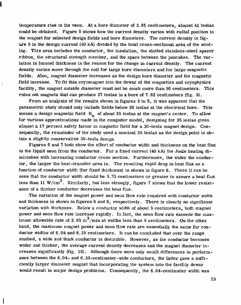
temperature rise in the neon. A t a bore diameter of 3.81 centimeters, almost 41 teslas could be obtained. Figure 5 shows how the current density varies with radial position in the magnet for selected design fields and bore diameters. The current density in fig- ure 5 is the design current (40 kA) divided by the total cross-sectional area of the wind- ing. This area includes the conductor, the insulation, the slotted stainless-steel spacer ribbon, the structural strength member , and the space between the pancakes. The var - iation in Inconel thickness is the reason for the change in current density. The current density varies more through the coil for large bore diameters and for large magnetic fields. Also, magnet diameter increases as the design bore diameter and the magnetic field increase. To f i t this cryomagnet into the dewar of the magnetics and cryophysics facility, the magnet outside diameter must not be much more than 50 centimeters. This rules out magnets that can produce 37 teslas in a bore of 7.62 centimeters (fig. 5).
parametric study should only include fields below 36 teslas at the electrical bore. This means a design magnetic field Bo of about 35 teslas at the magnet's center. To allow for various approximations made in the computer model, designing for 35 teslas gives almost a 17 percent safety factor in magnetic field for a 30-tesla magnet design. Con- sequently, the remainder of the study used a nominal 35 teslas as the design point to ob- tain a slightly conservative 30-tesla design.
to the liquid neon from the conductor. For a fixed current (40 kA) the Joule heating di- minishes with increasing conductor cross section. Furthermore , the wider the conduc - tor, the larger the heat-transfer area is. The resulting rapid drop in heat flux as a function of conductor width (for fixed thickness) is shown in figure 6. There it can be seen that the conductor width should be 5.71 centimeters o r greater to assure a heat flux less than 11 W/cm . Similarly, but less strongly, figure 7 shows that the lower resist- ance of a thicker conductor decreases the heat f lux.
The variation of the magnet power and neon flow rate required with conductor width and thickness is shown in figures 8 and 9, respectively. There is clearly no significant variation with thickness. Below a conductor width of about 5 centimeters, both magnet power and neon flow rate increase rapidly. In fact, the neon flow rate exceeds the max- imum allowable rate of 2.85 m /min at widths less than 5 centimeters. On the other hand, the maximum magnet power and neon flow rate are essentially the same for con- ductor widths of 6.04 and 6.35 centimeters. It can be concluded that over the range studied, a wide and thick conductor is desirable. However, as the conductor becomes wider and thicker, the average current density decreases and the magnet diameter in- creases significantly (fig. 10). Although there were only small differences in perform- ance between the 6.04- and 6.35-centimeter-wide conductors, the latter gave a suffi- ciently larger diameter magnet that incorporating the system into the facility dewar would result in major design problems. Consequently, the 6.04-centimeter width was
From an analysis of the results shown in figures 3 to 5, it was apparent that the
Figures 6 and 7 both show the effect of conductor width and thickness on the heat flux
2
3
13
I

selected as the better choice. In like manner, comparing performance factors and mag- net diameter suggests the best choice in thickness to be 0.18 centimeter. A composite plot of the various parameters discussed is shown in figure 11, where the parameters are plotted as a function of magnet radius and conductor current density.
Other independent variables included in this parametric study are axial packing fraction, coolant channel parameters, insulation thickness, and neon temperature rise. These will only be discussed qualitatively.
The axial packing fraction of the conductor affects the average current density; hence, it has a significant effect on neon flow rate and neon temperature rise. It should be as close to 1.00 as possible. The study shows, however, that a practical limit is 0.90 for uniformly spaced coils. This limit is dictated by the insulating radial stringers required between pancakes. However, there must be manifolds at the center plane; hence, a larger gap is required there to handle the flow. This reduces the overall axial packing fraction to 0.85, the value used in these calculations. The lower packing frac- tion reduces the field attained at a design neon temperature rise of 5 kelvins, but the field is still adequately greater than the desired operating field of 30 teslas. If the cir - culating pump in operation falls below the design flow rate, the design field can still be achieved by operating at a higher neon temperature rise. A s shown by the computed values in table ID, the designed magnet can operate with a ?-kelvin neon temperature rise and still have other parameters below the imposed limit discussed earlier in the report. However, the total available operating time for the magnet would be less at this greater temperature rise.
provides the passages for cooling the conductor. It was determined that for a 6-centimeter-wide conductor the openings in the slotted ribbon should permit about 70 percent of the conductor to be in contact with the neon. A smaller percentage would increase the heat flux, and a larger percentage would reduce the contact area for passing force radially between turns. Increasing the thickness of the slotted stainless-steel ribbon (and hence the coolant channel thickness) has an adverse effect on the heat trans- fer. A smaller thickness was considered impractical. The selection of coolant channel width and spacing was determined from various practical considerations. The values chosen for the coolant channel parameters were discussed earlier. The insulation thick- ness includes a 0.005-centimeter-thick polyimide insulating film and an adhesive layer no thicker than 0.01 centimeter. Choosing thinner insulation affects the other variables by less than 5 percent.
The slotted stainless-steel spacer ribbon shown in figure 2 and discussed earlier
Magnet Design
Values of independent variables were chosen on the basis of the results of the first
14

iteration of the mechanical design. Accurate values of the dependent variables are of course obtained only after the iteration proceeds to a self-consistent final design. Nine steps were used in the iteration procedure; however, after seven steps the design was in the range of fabrication precision.
Material physical properties from table I were used in these final design calcula- tions. The design results a r e shown in tables IV(a) and (b) . The differences between the two designs a re the result of different minimum structural thicknesses used in the computations. Near the outside of the magnet the required thickness of the Inconel structure becomes too small to permit easy handling, so a minimum thickness was im- posed, as indicated in equation (5). The most important difference between the two values considered, 0.0248 and 0.0124 centimeter, is that the thicker limit requires a
2 maximum force of 30.3 MN/m (4400 psi) to be passed between turns, while the thinner 2 limit requires only 24.6 MN/m (3570 psi). The design with a minimum Inconel thick-
ness of 0.0248 centimeter may be marginal since the turn-to-turn compressive force reaches 30.3 MN/m2, which is approximately the compressive yield of the pure alumi- num. Table III compares the operating parameters for the two designs a t design and slightly off-design conditions. Comparing the two designs and the operating results shows that the design in table IV(a) is the more conservative; therefore, it was selected as the more desirable design.
An enlarged gap at the center plane of the magnet is needed to accommodate the neon flow. This larger gap reduces the maximum magnetic field to about 32.7 teslas (fig. 12). Also shown in figure 12 is the field of a magnet that has uniformly spaced coils. In both cases the axial packing fraction is 0.85; however, the magnet with uni- formly spaced coils reaches a field of 35.1 teslas at the center plane. This field grad- ually drops off to 33.9 teslas a t a distance of 5 centimeters froni the center plane; then the field drops off rapidly.
The field on the axis of the designed magnet is 32.7 teslas at the center and varies less than d. 0 percent along a 13-centimeter length (fig. 12). The experimental bore radius is 3.18 centimeters. In this bore, the radial uniformity of the axial field is at least as good a s that on the axis except on and near the center plane, where the field decreases almost 3 percent (tables V(a) and (b)) . Otherwise, the large center-plane gap yields a larger test volume, which means a more uniform field over a large volume than for a magnet with uniformly spaced coils. The actual separation between the conductors within each pair of coils is 0.64 centimeter. The two magnet pairs have a conductor separation distance of 2.86 centimeters, that is, 1.43 centimeters from the center plane. The location of the coils is indicated in figure 12.
The axial and radial magnetic fields within the envelope of the magnet a re shown in tables V(a) and (b), respectively. The axial field in the array is positive until the 65th turn. A t this point, the axial field is negative between 4 and 10 centimeters from the center plane. Negative axial fields at the center plane to 12 centimeters from the center
15

plane occur from the 66th to the 73rd turns. Because of the large center gap, the radial magnetic field changes sign in a region near the center plane. Beyond 6 centimeters from the center plane, the radial field has the usual sign.
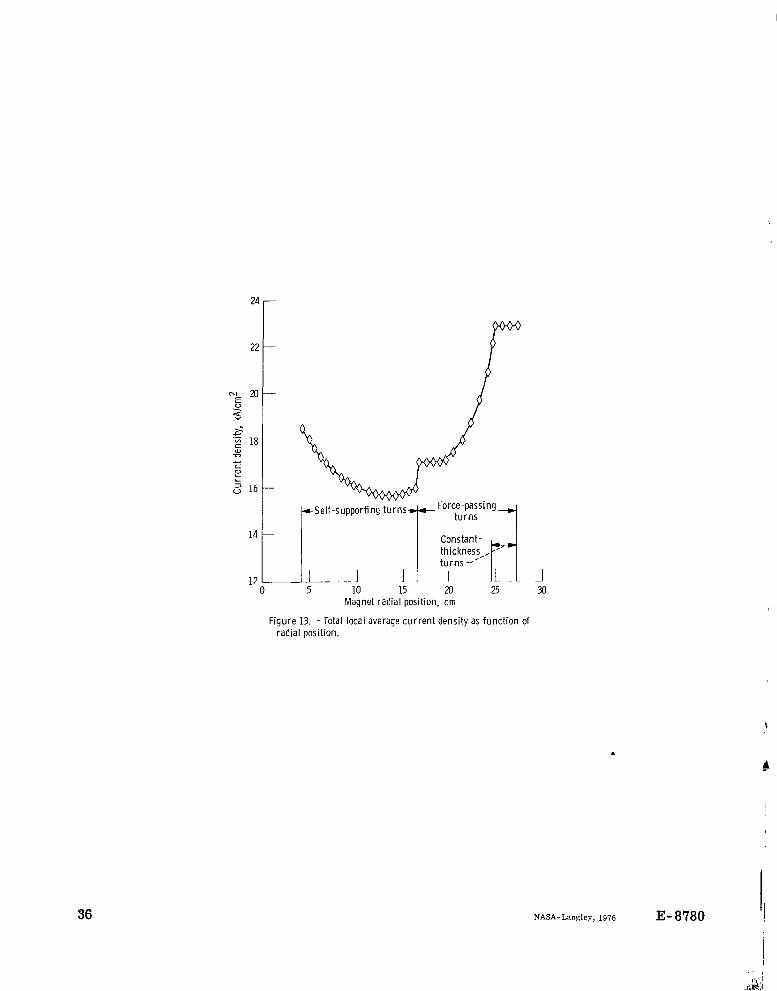
Figure 1 3 presents the total local current densities as a function of radial position for the design in table IV(a) . The radial location where turn-to-turn force passing be- gins is evident. Current density was constant in the last several turns of the coil be- cause the minimum structural thickness was reached.
CONCLUSIONS
A feasible design for a cryomagnet to produce more than 30 teslas was established by a computer study. The following results and conclusions were obtained:
1. A large-bore, 30-tesla cryomagnet can be constructed to operate continuously with the power and cooling available at the Lewis Research Center magnetic and cryo- physics facility. The final design gives a magnet with a uniform magnetic field over a length of 13 centimeters and a radius of 3.68 centimeters. Both axial and radial field uniformity is within *1 percent except at the center plane, where the radial field de- creases by less than 3 percent at the 3.68-centimeter radius. These results a r e based on the following magnet design concept:
a. Cooling by forced-convection, liquid-neon heat transfer, with a neon temper-
b . Tape-wound coil construction with a high-purity-aluminum conductor c. A large gap of approximately 3 centimeters between the two coils near the
d. Varying thickness of the structural member according to local requirements,
ature r i s e of 5 kelvins
magnet center plane
except near the outside of the magnet, where a minimum thickness (0.0124 cm) is imposed
2. The axial packing fraction must not be greater than 0.85 for adequate magnet cooling. A large gap between the magnet halves is required to accommodate coolant manifolds. In each half of the magnet the conductor begins 1 .5 centimeters from the center plane. The separation distance between the conductors in each magnet half is 0.635 centimeter.
3. The parametric study shows that the conductor should be between 5.0 and 6.5 centimeters wide and 0.175 and 0.180 centimeter thick. This would result in a magnet radius of about 25 to 28 centimeters. The selected design gives a radius of 26.9 centi- meters.
4. The selected design will have a minimum structural member thickness of 0.0124 centimeter. With a neon temperature r i se of 5 kelvins, the heat f lux will be 8.99 W/cm and the power 854 kilowatts. With a neon temperature r i s e of 7 kelvins, the magnet
16
2

would still be within other operating limits. The 854 kilowatts required at the design point means the magnet would operate at 30 teslas for more than 1 minute with the Lewis neon liquefaction system.
Lewis Research Center, National Aeronautics and Space Administration,
Cleveland, Ohio, June 22, 1976, 506-25.
17

I I I
*n
"i B
cP D
F
f
h
I
i
J
J -
k
m
N
Nu
n
Pr
P
Q q
Re
r
S
S
T
t
18
APPENDM A
SYMBOLS
area of conductor in contact with neon
inner radius of ith region
magnetic field strength
specific heat
hydraulic diameter
force
function
heat-transfer coefficient
current in each turn
index to various radial regions
current density
weighted average current density
thermal conductivity
magnet "pancake" index
total number of turns
Nusselt number
turn number index
Prandtl number
index of first not-totally-self-supporting turn
heat transfer o r power
turn where field reversal occurs
Reynolds number
radius coordinab
tensile s t ress
structural member
temperature
thickness

tAl
tC
'in
1 WA1
wC
wS
Y
P E
P
h e
Pnm
thickness of aluminum conductor
thickness of coolant channel spacer ribbon
thickness of insulation
thickness of structural ribbon in nth turn
velocity in innermost coolant channels
width of conductor
width of coolant channel
width of structural ribbon
Young's modulus
nondimensional coil-radius parameter (outer radius/inner radius)
nondimensional coil -length parameter (length/inner diameter)
strain
axial packing fraction of conductor
viscosity
density of neon
aluminum resistivity
19

APPENDIX B
WEIGHTED AVERAGE CURRENT DENSITY
The field at the center of a thin finite solenoid of half length 2 and radius a is
where n is the number of turns per unit length and po is the vacuum permeability. For a solenoid of radius r, incremental thickness d r , and current density J th is be- comes
PoJ dr dB =
Then for a thick solenoid, in which J may vary with r, integration gives
For the special case of constant J this becomes
Consider the following definition of a weighted average current density
20
with respect to
. .. . . .

1/2 the weighting factor [1 + (r2/Z3] :
Note that the current density at small values of r is weighted more heavily exactly in proportion to its effectiveness in producing a magnetic field, a s can be seen from equa- tion (B2). By using (B3) this may be rewritten as
which has the same form a s equation (B4) except that the constant current density J is replaced by the weighted average current density y. Because the available subroutine for calculating the field is exact when the current density is uniform but cannot deal with a variable J, the weighted average current density from equation (B5) was calculated and used. The field calculated in this way is therefore exact at the solenoid center but not at other points. Subdivision of the coil into a few radial sections, for each of which an average current density was calculated, and the addition of the field contributions of the sections provided the required accuracy at all points.
body of the paper by multiplying by Z -1, since the factor always appears simultaneously in the numerator and the denominator. In this report, Z is equal to 2(wA1/Xz). Sub- stituting this into equation (B5) and using summation notation yield equation (13).
c:
1, 2 2 -m
The weightirig factor [1 + (r /Z ,] can be put into the exact form used in the
21

REFERENCES
1. Laurence, J. C. ; et al. : A Large Liquid-Neon-Cooled Electromagnet. Proceedings of the International Conference on High Magnetic Fields, Ch. 15, The MIT Press and John Wiley & Sons, Inc., 1961, pp. 170-179.
2 . Laurence, James C . : High-Field Electromagnets at NASA Lewis Research Center. NASA TN D-4910, 1968.
3. Laurence, James C. ; et al. : Cryogenic and Superconducting Magnets. Plasmas and Magnetic Fields in Propulsion and Power Research. NASA SP-226, 1969, pp. 143-181.
4. Laurence, James C. ; and Coles, Willard D. : Design, Construction, and Perform- ance of Cryogenically Cooled and Superconducting Electromagnets. NASA TM X-52121, 1965.
5. Brown, Gerald V. ; and Coles, Willard D. : High-Field Liquid-Neon-Cooled Elec- tromagnets. NASA TM X-52119, 1965.
6 . Coles, W. D. ; Laurence, J. C.; and Brown, G. V. : Cryogenic and Superconduct- ing Magnet Research at the Lewis Research Center. NASA T M X-52627, 1969.
7. Brown, G. V . : High-Field Cryogenic Magnets with Pure Aluminum Conductor. NASA TM X-52571, 1969.
8 . Cardon, P. 0. : Design Principles Relating to the Strength and Structure of the ANU 30 T Electromagnet. J. Phys. E: Sci. Instru., vol. 5, 1972, pp. 654-656.
9 . Cardon, P. 0. : Design and Construction of the Inner Solenoid of the ANU 30 T Electromagnet. J. Phys. E: Sci. Instru., vol. 5, 1972, pp. 663-666.
10. Cardon, P. 0. : Testing the ANU 30 T High Field Magnet at Canberra. J. Phys. E: Sci. Instru., vol. 5, 1972, pp. 667-668.
11. Brown, Gerald V . ; and Flax, Laurence: Superposition Calculations of Thick Sole - noid Fields from Semi-Infinite Solenoid Tables. NASA TN D-2494, 1964.
12. Papell, S . S . ; and Hendricks, R . C. : Liquid Neon Heat Transfer as Applied to a 30-Tesla Cryomagnet. NASA TM X-71712, 1975.
13. Corruccini, R. J. : The Electrical Properties of Aluminum for Cryogenic Electro- magnets. NBS TN-218, 1964.
22

TABLE I. - PHYSICAL PROPERTIES OF MATERIALS USED
f '
w
IN COMPUTER STUDY
Aluminum: ' Resistivity at room temperature, S1-m . . . . . 2.8X10m8 Resistivity a t 28 K, O-m . . . . . . . . . . . . 4.88X1O-l1 Residual resistivity ratio . . . . . . . . . . . . . . . -2000
Inconel 718: 2 Yield strength, N/m . . . . . . . . . . . . . . . 1 2 . 7 ~ 1 0 ~
Tensile strength, N/m2 . . . . . . . . . . . . . 1 6 . 8 ~ 1 0 ~ Area reduction, percent . . . . . . . . . . . . . . . . . 25 Elongation at 20 K, percent . . . . . . . . . . . . . . . 30
Mass density, kg/m . . . . . . . . . . . . . . . . . . 1200 Viscosity, kg/m-sec . . . . . . . . . . . . . . . . 0.00012 Thermal conductivity, W/m-K . . . . . . . . . . . . 0.126 Heat capacity at constant pressure, W-sec/kg-K . . . 1950 Heat of vaporization at 28 K, J/kg . . . . . . . . . . 8 5 ~ 1 0 ~
Neon: 3
-.. - ._
aIf not noted, properties are in 25 to 40 K range.
Magnetic field, T . . . . . . . . . . . . . . . . 35 Conductor current, kA . . . . . . . . . . . . . 40 Distance of start of conductor winding
from magnet centerline, cm . . . . . . . . 3.8 Axial packing fraction. . . . . . . . . . . . . 0.85 Coolant channel width, cm . . . . . . . . . . 0.45 Coolant channel thickness, cm . . . . . . . 0.038 Coolant channel spacing, cm . . . . . . . . . 0.64 Conductor thickness, cm . . . . . . . . . . 0.180 Conductor width, cm . . . . . . . . . . . . . 6.04 Insulation thickness, cm . . . . . . . . . . 0.015 Neon inlet temperature, K . . . . . . . . . . . 28 Rise in neon coolant temperature, kelvin . . . 5.0
TABLE II. - FINAL MAGNET DESIGN RESULTS
(a) Input variable (b) Output variable
Magnet outside diameter, cm . . . . . . . . . . 54 Reynolds number . . . . . . . . . . . . . . 1. 62X104 Magnet pressure drop, N/m . . . . . . 2.6X10⁴ i Magnet power required, kW Magnet neon flow rate, m /min . . . . . . . . Neon use rate, m /min . . . . . . . . . . . . 0.49 Average conductor temperature, K . . . . . . 35.7
Dynamic resistivity ratio . . . . . . . . . . . . 109
2
Magnet coolant channel heat flux, W/cm . . . 8.99 . . . . . . . . . . . 855
3 2.78 3
Maximum conductor temperature, K . . . . . 37.0
23

TABLE III. - COMPARISON OF MAGNET OPERATING PARAMETERS
Minimum thickness of Inconel 718
structural ribbon, cm
a O . 0124
aO. 0248
Neon temper- Heat flux, ature r i se , W/cm2
kelvin
_ _
a5 8.99 6 9.60 7 10.24
a5 8.98 6 9.60 7 10.23
~
Power, kW
854.5 914.1 974.9
854.5 914.0 974.7
~-
Neon flow rate, 3 m /min
2.78 2.46 2.23
2.78 2.46 2.23
Neon use rate, 3 m /min
0.488 .522 .557
0.488 .522 .557
~.
Magnet center- plane force,
N
24

TABLE IV. - FINAL MAGNET DESIGN
(a) Assuming a minimum Inconel-718 structural ribbon thickness of 0.0124 centimeter
:urn Magnetic Average Thickness of Length of Overall Force Force Turn Magnetic Average Thickness d Length of Overall Force Force I
___------- ~ - - - ---
field, turn di- lnconel 718 aluminum current received passed field, turn di- Inconel 718 aluminum current received passed
41 42 43 44 45
46 47 48 49 50
51 52 53 54 55
56 57 58 59 60
61 62 63 64 65
66 61 68 69 70
71 I2 73
T ameter, structural conductor, density, by turn, by turn, T ameter, cm ribbon, m kA/cm2 kN kN cm
cm --- ---A! 4-- 12.85 12.35 11.85 11.35 10.86
10.32 9.73 9.15 8.58 8.01
1.45 6.89 6.33 5.18 5.24
4.70 4.17 3.65 3.14 2.65
2.10 1.46 .85 .27
-.31
-.89 -1.48 -2.06 -2.63 -3.20
-3.80 -4.45 -5.12
1 2 3 4 5
6 I 8 9
10
11 12 13 14 15
16 17 18 19 20
21 22 23 24 25
26 27 28 29 30
31 32 33 34 35
36 31 38 39 40 -
0
i 39.1
35.25 34.66 34.06 33.47 32.86
32.26 31.65 31.04 30.44 29.83
29.21 28.60 27.99 21.38 26.17
26.19 25.64 25.09 24.55 24.00
23.46 22.92 22.38 21.84 21.31
20.17 20.24 19.71 19.18 18.66
18.12 17.57 17.02 16.41 15.93
15.39 14.86 14.36 13.85 13.35 -
225 260 294
325 359 388 419 447
469 499 522 545 565
584 600 615 829 641
651 659
.665 668 660
639 608 566 509 443
363 270 158
8.24 8.84 9.45
10.07 10. 70
11.32 11.98 12.61 13.29 13.93
14.60 15.28 15.94 16.63 11.32
19.18 18.69 19.40 20.10 20.8
21.5 22.2 22.9 23.6 24.3
25.1 25.8 26.5 27.2 27.9
28.6 29.4 30.1 30.8 31.5
32.2 32.9 33.6
34.9 34. a
-
260 294 325
359 388 419 447 469
499 522 545 565 584
600 615 629 641 651
659 665 668 660 639
608 566 509 443 363
270 158 39.9
0.0698 ,0736 ,0775 ,0810 .0846
.0818
.0911
.0942
.0973 ,1000
,1027 .lo52 .lo74 .lo93 ,1116
.1132
.1152
.1110
.1187 ,1200
,1212 . E 2 5 .1231 .1241 ,1248
,1252 .1254 ,1256 .1254 ,1252
.1250 ,1239 .1232 .1219 .1201
.1200
.0961
.0968
.0970
.0970
I
0.244 .549 ,824
1.159 1.495
1.830 2.230 2.625 3.02 3.48
3.94 4.42 4.91 5.42 5.96
6.56 7. 14 7.75 8.39 9.02
9. 70 10.40 11.22 11.84 12.60
13.41 14.22 15.02 15.90 18.79
17.67 18.59 19.58 20.50 21.50
22.50 23.55 24.60 25.65 26.75
18.59 18.35 18.13 17.92 17.72
17.54 17.36 11.20 17.04 16.90
16.77 16.65 16.53 16.43 16.34
16.25 16.16 16.08 16.00 15.94
15.88 15.83 15.19 15.16 15.13
15.71 15. IO 15.69 15.69 15.10
15.13 15.76 15.80 15.85 15.91
15.98 17.10 17.07 11.05 11.05 -
0
1 17.6
115.5 152.8 1
35.6 36.2 36.9 37.5 38.2
38.8 39.5 40.1 40. I 41.4
42.0 42.6 43.3 43.8 44.5
45.1 45.6 46.2 46.8 41.4
41.9 48.4 48.9 49.4 49.9
50.4 50.8 51.3 51.8 52.3
52.8 53.3 53.6
-
structural conductor, density. by turn, by turn,
27.85 29.00 30.20 31.35 32.60
33.80 35.05 36.30 31.60 38.85
40.1 41.2 42.9 44.3 45.6
41.1 48.6 49.9 51.4 52.9
54.4 56.0 51.5 59.0 60.6
62.1 63. I 65.4 61.0 68. I
IO. 3 12.0 73. I

- *urr
- 1 2 3 4 5
6 7 8 10 9
11 12 13 14 15
16 11 18
dagnetii field,
T
19 20
21 22 23 24 25
26 27 28 29 30
31 32 33 34 35
36 37 38 39 40
I
35.22 34.63 34.03 33.43 32.83
32.23 31.62 31.01 30.40 29.79
29.18 28.57 27.96 21.35 26.74
26.15 25.61 25.06 24.51 23.91
23.42 22.88 22.34
.verage urn di- meter
em
8.24 8.84 9.44 10.05 10.69
11.31 11.97 12.62 13.29 13.95
14.60 15.21 15.95 16.65 17.33
18.01 18. I1 19.39 20.10 20.80
21.50 22.20 22.90
21.80 23.60 21.27 24.35
20.13 25.05 20.20 25.8 19.61 26.5 19.14 27.2 18.61 21.9
18.07 28.6 17.52 29.4 16.91 30.1 16.46 30.7 15.95 31.4
15.44 32.1 14.92 32.8 14.41 33.4 13.89 34.1 13.38 34.8
TABLE IV. - Concluded.
@) Assuming a minimum Inconel-718 structural ribbon thickness of 0.0248 centimeter
hickness of nconel 718 structural
ribbon, cm
0.0696 ,0736 .0712 .OB10 ,0643
,0878 .0909 ,0942 ,0970 .0998
.lo22
.lo49
.lo72
.lo93
.1112
.1132 ,1150 .1169 .1183 ,1198
,1210 .1222 ,1231 ,1238 ,
,1243
.1250
.1252
. 1252
.1252
.1250
.1243 ,1239 .lo04 .lo20 .lo31
.lo40 ,1049 ,1058 ,1060 .lo61
>ength of luminum onductor,
m
0.244 .549 ,824
1. 159 1.495
1.830 2.230 2.625 3.02 3.48
3.94 4. 42 4.91 5.42 5.96
6. 56 I. 14 I. 75 8.39 9.02
9. 70 10.40 11.22 11.84 12.60
13.41 14.22 15.02 15.90 16. I9
17.67 18.59 19.53 20.50 21.5
22.5 23.5 24. 6 25. 6 21. I
- hera l l :urrent Ienaity .A/"
- 18.59 18.36 18.13 17.93 11.13
17.54 17.37 17.20 17.05 16.91
16.78 16.65 16.54 16.44 16.34
16.25 16.17 16.09 16.01 15.95
15.89 15.84 15.80 15.77 15.74
15.12 15. 71 15.71 15.71 15.12
15.14 15.78 16.81 16.80 16.14
16.69 16.65 16.62 16.60 16.59
- Force !ceive( y turn, kN
- 0
lf
- Force iassed y turn
kN
- k r r
- 41 42 43 44 45
46 41 48 49 50
51 52 53 54 55
56 51 58 59 60
61 62 63 64 65
66 61 68 69 70
71
40.8 13 , 11 72
40.8 81.2 81.2 121.2
121.2 156.5 156.5 200.0 200.0 239 239 216 276 314
- Iagnetic field,
T
- 12.86 12.35 11.83 11.32 10.81
10.27 9.68 9.10 8.53 I. 96
7. 40 6.84 6.29 5.14 5.20
4.61 4.15 3.63 3.12 2.64
2.10 1.49 .91 .33
-. 26 -.84 -1. 42 -2.00 -2.58 -3.15
-3.14 -4.38 -5.06
- werage turn di ameter
cm
- 35.4 36.2 36.8 37.4 38.2
38.3 39.5 40.2 40.8 41. 4
42.1 42.8 43.4 44.0 44.6
45.2 45.9 46.4 47.0 41. 5
48.1 48.6 49.1 49.6 50.1
50.6 51.1 51.6 52.1 52.6
53.3 53. 7 54.2
hickness d nconel 118 structural
ribbon, cm
0.1060 ,1058 .lo52 ,1020 ,1034
.lo15 ,0990 .0962 .0932 .OB99
,0861 ,0820 .0717 .0729 .0681
.0627 ,0571 ,0513 ,0451 .0391
,0318 ,0248
.en& of luminum onductor
m
27.8 29.9 30.1 31.3 32.5
33.75 35.0 36.3 37.6 38.85
40.1 41.2 42.9 44. 3 45.6
47.1 48.6 49.9 51.4 52.9
54.4 56.0
' 59.0 60.6
62.2 63.9 65.5 67.2 68.9
IO. 5 72.3 14.0
, 57.5
- lverall urrent ensity A/cm'
~
16.60 16.61 16.64 16.68 16.14
16.82 16.95 17.09 17.25 17.43
11.63
i1
17.86 18.11 18.39 18. I O
19.03 19.40 19.80 20.23 20.68
21.25 2
I1
Force *eceivec oy turn, kN
- 314 350 386 421 455
481 519 550 580 602
634 659 682 704 723
138 759 775 789 718
811 818 821 815 797
167 126 674 608 531
441 339 222
'orce assed Y turn,
kN
3 50 386 421 455 487
519 550 580 602 634
659 682 704 123 738
159 775 189 179 811
818 821 815 791 167
72 6 674 608 531 441
339 222 90

TABLE V. - MAGNETIC FIELDS FOR FINAL MAGNET DESIGN
0.06 1 0.08 1 0.10 0.12
I-"
0.14 0.16
- n
21.782 21.394 21.006 20.617 20.228 19.839
- - Turn
-- I 1
3 4 5 6 7 6 9
1 3 11 12 13 l't 15 ?6 17 l e 19 2 3 21 z z 23 24 2 5 it, '7
29 3? 3 1 >2 >, 34 3 5 36 37 38 39 4 3 41 +2 P3 c4 $5 46 47 4c t')
jq j l j 2 53 54 ,5 56 57 5 A >Q
,? >1 i 2 i 3 14 55 50 ' 7
>
2.3
,
69 7 3
Dis- tance from cen- ter- line, cm
3. 1.113 k.416 P. 72 2 5.?33 5.347 5.6b5 j.YJ6 5.313 5.637 5.967 7.333 7.b3b 7.974 J .315 4.65 I 9 . 2 3 2 J .349 ::.6Y7 1.747 1.399 1.752 1 . 1 2 0 1.46% l . H ? Y 1.176 ?. 5 3 4 ! . H C I 2 3.257 5.639 ).')>?I e.320 + . a d + < . 7 4 1 T.3cid 5.753 >. 1: I r . 4 5 ' ) I. 78d 1 . 1 l a 7.44d 1.771 1.17!1 1.43d 5.76.) ' . ? 9 0 ? . 4 ? 4 3.753 ' * 17'1 I . 3 9 5 ' . 7 1 4 . ?: 9 . . 3 4 1 ..t4Li . .953 ' .252 .5*7
: .837 I .125 i..+ni 1.676 1.945 t.2Cl7 r.45; t.716 . .95?
1 9 7 t.443 t . h S a i .934 : . l a 7 , .425 , e 6 7 1 8.91" ~
0
32.*51 31.157 33.d55 31.513 3?* 1 3 5 29.729 29.298
2 5 - 3 8 > 27.905 27.417 26.922 210.421 25.017 i 5 . 4 1 > 24.9 I* 2 4 . 2 4 n 23.894 23.347 22.809 22.3u7 21. Hr(7 Ll- 3 b h 22.686 29.3 h5 19.834 19.383 1J.dB2 1.1.379
17.372 l b - 8C.6 lo. 35H 15.tl5l 1 9 . 3 4 2 14- 834 14. 526 1J.YlY 13.344 12.865 12.385 11 .y-1 11.414 13.922 17.427 Y.926 7.419 d.92') a.3Y6 7. $31 7.307 0.854 6.343 5.836 5.332 4.H33 4.339 .3. ti49 3.364 2.845 2.411 1.944 1.487 1. I 4 5 1.618 9. 196
-1 .621 -1.9lO -1.3R9 -1.727 -2.346 -2.333 -2.585
28. ~ 4 6
1 7 . ~ 7 6
-? .21a
I 0.02 I 0.04 1
52.711 32.642 32.081 3 1.545 31.319 33 .497 2Y.975 29.449 28.921 28.389 27.854 27.316 26 .774 26.229 24.681 25.120 2 4 - 6 3 ? 24 .105 23 .604 23.192 22 .598 22.394 21.593 2 1. I d 7 29.583 27.381 10 .579 19.378 13.57')
17 .587
lb.55d 16. 342 15 .528 15.916 14 .5?7 14 .333 13 .526 13 .952 12 .577 12 .112 11.627 11.153 11. b 8 1 1 3- 2 2 4
'3.721 9.164 8 .027 8.397 7 .577 7.349 6.535 6.323 5.519 5.723 4.534 4.753 3.582 3 .132 2.717 2.239 1 . 6 5 9 1.123 3.b17 1.116
-3.384 -9.882 -1 .377 - l .d7 '? -2.36H -2.897 -3.513 -4 .183
19. ?Hi
i7.:r)
32.774- 33.487 32.877 32.268 31.666 31.069
29.686 29.330 2R3.716 28.133 27.552 26.971 26.391 2 5 . R l l 25.231 24.685 24.177 23.b70 23.163 22.657 22.151 21.646 21 .143 2".640 2". 14'3 I F - 6 4 1 19.145 lH.653 10.158 17 .671 17.166 16 .646 16.132 15 .621 15.112 14.697 14 .106 13 .639 13.173 17.738 12.244 11.781 11.319 19.859 13 .412
9.41 1 9 .351 8.898 6 - 2 7 > 7.737 7 - 239 6.637 6.172 5.664 5.163 4.668 4.189 3.698 3.233 2.794 2.271 1.648 1 .953 3.484
-0 .Ot l8 -0.663 -1.242 -1.822 -2.4Q2 -2.988 -3.633 -4.298 -5.?25
30.476
32- 6 3 6 33. 1 3 4 32.495 31.887 31.285 30.688
29.532 28.Y13 28.326 27.741 27.157
30.094
26.574 25.993 25.412 24.034 24 .289 23.7R4 z 3 . 2 8 0 22.778 22.277 21.778 21.231 2 0 . 786 2'). 293 19. B O 3 19.314 18.829 lfl. 346 17 .865 17 .389 16.896 16. 391 15.889 15. 391 14.895 14.404 13.916 13.461
12 .553 12.171
13. "07
11.649
10.746 11.:97
19.309 9 . R 1 8 9.266 8.73 1 8.211 7.673 7 - 1 5 7 6.632 ~~
6.119 5.611 5.109 4.612 4.120 3.634 3.164 2.719 2.19 1 1.564 1.964 9 - 3 9 1
-3.183 -0.76 1 - 1.341 -1.921 -2.503 -3.084 -3.697 -4.393 -5. 1 1 4
31.52 1- 31.499 31.568 30.566 30.135 29.493 28.936 28.377 27.816 27.255 26.693 26.133 25.574 25.318 24.466 23.924 23.431 22.903 22.478 21.Y21 21.438 23.958 2 3 - 4 8 > 20.305 19.533 19.063 18.595 18.129 17 .666 17 .293 16.741 16 .271 15. 795 15.319 14.845 14.373 13.994 13.438 13 .713 12 .568 12 .133 11.698 11.262 17.823 17.387
Y.931 9.456 d.956 d.452 7.945 7.439 6.935 6 .434 5.936 5.442 4.951 4.462 3.976 3.490 3.035 2.516 1.995 1.441 0.891 9. 352
-3.191 -0.736 -1.281 - 1.827 -2.353 -2.866 -3.373 -3.861 -4.288
29.759 30.448 29.862 29.279 28.734 28 .135 27 .571 27.?12 26.457 25.906 25.358 24.813 24 .271 23 .731 23.193 22.653 22.159 21.699 21.242 2?.787 20.333 19.8R3 19 - 4 3 4 18.988 18.544 18 .133 17. h64 17 .229 16.796 16.366 15 .947 15 .503 15.144 14 .593 14.146 13.791 13 .261 12 .824 12.416 12 .312 11.627 11.234 11.031 1C.3'49
9.998 9.611 9.169 3 - 6 6 6 8.183 7.698 7.218 6.742 6 .271 5.834 5.341 4.883 4.429 3.979 3.533 3.101 2.693 2.199 1.604 1.935
' " 3 5 9 -0.611
0.489
-1.16d -1.725 -2.284 -2.848 -3.442 -4.117 -4.824 _ _ ~
27.134 27.946 27.391 26.842 26.393 25.774 25.254 24.740 24.233 23.731 23.233 22.739 22.247 21.75R 2 1.273 23.785 27.333 19.921 19.511 19.192 18.691 18 .286 17 .881 17.477 17.075 16.674 16.276 15 .R81 15.488 15.097 14 .711 14.313 13.892 13.4fl9 13.071 12.666 12 .264 11. I366 11.496 11.127 13.763 17.394 10 .931
9.668 9.308 8.962 8 - 5 6 1 8.172 7.659 7.221 6.787 6- 3 5 8 5.933 5.514
4.691 4.286 3.886 3.490 3.108 2.749 2.303 1.755
5. i eo
1.233 0.727 0.221
-0.292 -0.810 - 1.333 - 1.858 - 2.392 -2.959 -3.611 -4.297
23.541 19.681 23.833 18.886
I 23.367 22.959 22.563 22.172 I
I 19.449 19.358 18 .665 18 .270 17.897 17.552 17 .203 16.853 16 .533 16.153 15 .802 15.452 15.1?2 14.753 14.405 14.357 13.711 L3.366 13.725 12.672 12 .306 11 .946 11 .587 11.231 13 .876 13.524 I?. 1 9 6
9.868 9.54c 9.213
I 8.886 8.56n 8.236 7.928 I 7.578 7 .183 6.895 6.433 6.063 5.697 5.335 4.978 4.625 4.276
I 3.932 3.593 3.260 2 - 9 4 3 I 2.652 2.298 1 .86t 1.462 1 . 0 R O 9.699
I 0.317 -0.066 -3.449 -0.833
18.724 18.543 18.344 18.131 17.994 17.666 17.419 1 7 e l h 3 16.901 16.633 16.361 16. 285 15.805 15.524 15.241 14.557 14.672 14.385 14.098 13.899 13.519 13.227 12.935 12.641 12.346 12. ? 5 3 11.753 11.455 11- 155 10.855 10 .553 10.251
9.948 9.645 9 .342 9.340 8.756 8.471
7.896 7.606 7.315 7.021 6.726 6.429 6.131 5.832 5.534 5.236 4.941 4.647 4.356 4.968 3.784 3.503 3.225 2.953 2.684 2.420 2.162 1.910 1.668 1 .436 1 .297 0.982 0. 764 0.553 3.352
a. i n 4
27

TABLE V. - Concluded.
(b) Radial --
Distance from center plane, m
0 0.02 0.04 1 0.0y L 0.1: ~~
Magnetic field, T
~. 1.
- 1 . l d 7 -1. a s 0 -1 .492 -1 .596 -1.675 -1.135 - 1.779 - ? . d l : -1.!133 - 1. n47 - 1 . H 5 3 - 1 . J j 4 - 1 . 8 4 3 -1 . t I3h -1 .813 - 1. 79 I -1.776 - 1.75u - 1. 744 - 1.731 -1.719 - ! . 7 1 ? -1.771 - 1.694 - Imbed -1.06* -? .581 -1.681 - 1 . 6 8 2
- 1.693 -1.733 -1.735 -1.717 -1. 1 1 4 -1.71Y -1.725 -1.732 -1.74, -1.751 - 1.763 -1.77d -1.797 -1.321 -1.R5C -1.983 -1.913
- 1 . 9 5 n -1.975 -1.993 - 2 . 9 3 3 -2.716 -2 . ?2:, -2 .24? -?. 352 -2.366 -2 .381 -2.799 -2.127 -2.13d -2.147 .2.142 .2.123 .La 391 .2.345 .1.983 -1.914 .1.394 .I.6!33 ,I. 527
- ? . b a r
-1.938
_ _ _ 3.
-9.11F - P . 13 ; -3.144 -Q. 15: -0 .15t -7.155 -0.151 -5.151 -?. 141 -,>.12s -3.112
-,?.774 -n. ?5? -?. P25 -r?.795
'!.?23 5 . 9 4 5 " 9 6 9 3.?93 3.117 C . 139 o. 1111 r?. 1 8 1 ?.2?1 3.2 17 0.233
C. 2 6 ? P.272 0.282 P. 290 " 2 9 7 ? . 3 " i ?. 306 -. 3'?9 3.31- 1 . 3 c 9 3.337 3.334 ?. 299 9.293 q.285 " .?76 7.267 9.257 7.246 3.235 P. 224 9.214 3.273 9. 193 '1. I 8 4 ?.17b ?. 169 ".1C3 0. 159
9.156 9.15R C. 163 ? . I 7 1 n. lH1 7.195 3.212
?. 257 C.285 3.316
351 3.3Hd 0.42 7 2.468
-n.n95
?.24n
n. 156
0.232
. 7; 9.881 0.955 1.227 1.096 1.161 1. 223 1.282 1.339 1.395 1.449 1. 5-2 1.553 1. 694 1. h53 1.737 1.747 1 . 7 9 3 1.833
1.926 1.9hH 2.2?8 2.$48 2.19s 2 .121 2. 1 5 5 2.138 2.219 2.247 2.273 2.297 2.319 2.33v 2.356 2 - 3 7 ?
2. 393 2.47 3 2.49b 2.410 2.413 2 - 4 1 5 2.41 5 2.414 2.41 2 2.499 2.494 2.397 2.389 2.379 2.369 2.35 7 2.345 2.333 2.923 2.328 2.296 2.285 2.274 2.263 2.251 2.239 2.226 2.211 2.195 2. 176 2.154 2.128 2.103 2. ,C68 2.732 1.993 1.952
i . o a 2
2 . 3 8 2
- I. 1.2c5 1.276 1.354 1.442 1. 532 1.624 1. 716 1.8?7 1.1197
7. - 7 4 2. lb'? 2.245 2 . 3 2 9 2 . 4 1 3 2.499 2.579 L. 653 ?. 725 2.793 2.857 2.922 2. 9H2 3 - 9 4 ] J. ?94 3.146 3.194 3.243 3.262 3.319 4.352
3.412 1.439 3 - 4 6 3 3.463 3 . 5 2 1 3.514 3.525 3.533
3.54- 3.539 3.534 3.523 3.524 3.4b7 3.472 3.455 3.436 3.415 3.391 3.366 3.337 3 . 3 9 9 3. L7d 3.245 3 -21? 3.171 3.126 3.976 4.337 2.989 2.951 2.714 2.817 2 . 5 3 9 2.873 2.767 2.735 2.739 2.595 2.724
1 . 9 ~ 6
3 . 3 8 3
3.538
. . .
'?. 2.055 2.185 2.317 2.449 2 .583 2.717 2.851 2.985 3.116 3.246 3.37'* 3.493 3.621 3.741 3.855 3.766 4.774 4.177 4.?76 4.371 4.462 4 . 5 4 9 4.b31 4.7n9 4.78 3 4. a 5 3 't.918 4 .9d1 5.337 5.377 5.139 5 . l d 3 5.224 5.261 5 .294 5 - 3 2 2 5.347 5.366
5.392 5 - 4 1 ] 5.4?3 5.472 5.396 5.386 5.372 5.354 5.333 5.307 5.277 5.244 5.217 ¶. 166 5.121 5.372 5 - 3 2 , 4.964 4.905 4.844
4.715 4.640 4.504 4 - 5 2 ? 4.455 4.389 4.324 4.263 4.196 4.133 4.772 4.111 3.151
5 .381
4.783
. .
0.12- 1
3. 3.3?3 3.538 3.769 3.994 4.213 4. 424 4.628
5. " 3 5.194 5.367 5.532 5. bQ? 5.841 5.935 6.122 6 . 2 5 4 b. 3277 6-5?1 6. h17 h. 72R h. n34 6.935 7.?3Z 7.124 7.211 7.294 7.373 7.44 7 7 .51h 7.551 7.641 7. h 9 6 7.747 7.792 7. f333 7.809 7.89R 7.923 7.945 7.962 7.175 7 .984 7.98') 7.9RH 7.982 7.971 7.954 7.932 7.9P3 7.869 7.828 7. 732 7.733 7.672 7. 6?9 7.543 7.466 7.386 7.337 7.299 7.113 7. C12 6.907 6.795 6.676 6.549 6.414 6.274 6.127 5.974 5.813 5.658
4.825
-_
0.14 I ~
__ 3 . 4.843 5.33c 5.692 6.347 6.354 6.h43 h e 9 1 2 7.159 7.391 7.613 7.014 ,9.11)5 8.184 4.349 8.499 8.635 6 .769
9 . 1 3 4 1 .161 0.2H4 9.4?2 9.517 9.6?6 9.731 9.832 4.929
12.72z 13.112 13.21: 1 ?. 286 L3.364 11.433 13. $96 !? .552 10.6?2 IP.040 1?.686 19.721 19.752 K . 7 8 7 10.R-Jf: 1 r. 8 3 " 11.355 1T.f l83 1?.012 17.926 1?.Y29 11.917 L7.d96
1?.92H 17.784 1O.732 LC.075 12.613 11.547 : - .479 1 2 . 4 1 1 19.345 17.277 13.192 1?.7R5
9.967 9.315 9.549 9.462 9 . 2 5 1 9.914 5.745 P.'+37 R.777 7.661
n . l i 1 3
1?.a66
~~
0.16 ~
~
7. 3-90': 4.275 4 - 5 6 : 4. d3< 5 - 1 2 : 5.3hr: 5.604 5.836 6 . 258 6.271 6. 471 6. 663 e. R45 7.q1r 7.183 7.343 7.497 7.634 7.771 7.$33 8.339 8.151 R. 267 8.378 8.484 8 . 5 8 5 8.h81 U.772
8.94? Q.716 9.766 9.151 9.211 9.265 7.313 9 . 356 9. 392 9.424 Y.451 9.474 9.452 P. 5 3 6 9.515 0.519 9.517 9 . 5 @ 9 9.493 9.471 9.442 9.4P6 9. 362 9.312 Y. 255 9.191 9.121 9.744 8.961 8 .875 8.773 8.668 8.556 8 . 437 R. 312 8. 176 8.339 7.873 7.776 7.528 7.34') 7.144 6.541 h.733
6 . n59
-. . -
28

PUA
CORE 7 I
TO VENT TANK
I t I ,rPRESSUREVESSEL (2.8 MN/m2 (400 psi))
-MAGNET COIL (4)
-HEAT EXCHANGERS
rL1QUID NEON
CS-74125
(a) Conceptual design.
MAGNET SYSTEM i I N L a TO (2.75 MNlm2 (400 p s W ' CRYOSTAT
(b) Cutaway. Figure 1. - Thirty-tesla magnet system.
29

' ING 8T
zlNCONEL 718 'L ADHESIVE BOND
Figure 2 - Conceptual design of 30-tesla, liquid-cooled magnet (ent ire system enclosed in cryostat).
4
c
30

1400
1200 z i c al
P looo- E 0 L
L B 800- U
=i
ce
E
4 .-
400-
Bore diameter, cm
0 7.62 6.35
0 5.08 0 3.81
-
-
600-
38 40 42 I
36 32 Center-plane magnetic field at electrical bore, T
I 34
I
Figure 3. - Power required to reach various magnetic f ield for dif- ferent bore diameters. (Heat flux varied from 9.98 Wlcm 3 at 31 T to 10.46 W/cmP at 41 T. 1
5.5 5.0 L 4.5 c
E 3.5 2- e 4.01 B 3.0
3 2.5
c
1.5
1.0 30
Bore diameter, cm
0 7.62 6.35
0 5.03 0 3.81
Figure 4. - Neon flow rate required to maintain 5-kelvin temperature rise at various magnetic fields and bore diameters.
31

70
80-
-
6-
50-
40-
30-
20+
Magnetic field strength,
T 0 31 0 31 4 41 0 37 0 41
26
Bore diameter,
cm 3.81 7.62 3.81 7.62 7.62
-
Turn diameter, cm
Figure 5. -Cur ren t density as function of turn diameter for various design magnetic field strengths and bore diameters. Conductor width, 5.71 centimeters.
Conductor thickness,
cm e 0.1750 --o-- . 1 m -- . 1 m
.1950 --a--
Ol! 2 3 4 5 6 7
Conductor width, cm
Figure 6. - Heat flux as function of conductor width for various conductor thicknesses and a fixed cur ren t of 40 kiloamperes.
a li

1700 -
Conductor width,
cm 0 6.35 0 6.04 A 5.71 0 5.40 - 0 5.08
Conductor thickness,
cm 0 0.1750 0 0.1750
8002 I-Lu-u 3 4 5 6 7
Conductor width, em
Figure 8. - Magnet power required as function of conduc- tor width and thickness.
W w

Conductor thickness,
cm 0 0.1750 + .1180 0 . 1 m 0 ,1900
.19%
62 r Conductor thickness, 9
cm /
I 8 I
W c
U
46-
2 3 4 5 6 1 Conductor width, cm
Figure 9. - Required neon flow rate as function of con-
2.5
ductor width and thickness.
42 - 2 3 4 5 6 1
Conductor width, cm
Figure 10. - Magnet outside diameter as function of con- ductor width and thickness.

Conductor width,
c>
c1
34
30 + Q al - .- c ._ u 26
m
c m c
2
L 0 c 5 0 1
r Un i fo rm coi l spacing A
-
-a
- pairs, 0.635 cm; distance from center plane, 1.43 cm)
-
.35
I I 22 24 26 28 30
18
1 A
Conductor thickness,
cm 0 0.1750 0 ,1800 0 .19CQ A .1950
- -Inboard co i l 3, i[ Designed magnet
I
Magnet radius, cm
F igu re 11. - C u r r e n t densi ty as func t i on of magnet radius for var ious conductor thicknesses.
0 2 4 6 8 10 12 14 16 Distance from center plane, cm
Figure 12. - Comparison of magnetic f ie ld along axis for un i fo rm co i l spacing and for de-
A-
signed magnet. Axial packing fract ion, 0.85 in both cases.
35
36
12 0 5 10 15 20 25 30
Magnet radial position, cm
Figure 13. - Total local average current density as function of radial position.
NASA-Langley, 1976 E- 8780
c
I II I IIIIII Ill11 I l l I1
NATIONAL AERONAUTICS A N D SPACE ADMINISTRATION WASHINGTON. D.C. 20546 P O S T A G E A N D FEES P A I D
.____ N A T I O N A L AERONAUTICS A N D OFF1 C I AL BUS I N ESS SPACE A D M I N I S T R A T I O N
PENALTY FOR PRIVATE USE $300 SPECIAL FOURTH-CLASS RATE 451 USMAIL
BOOK
845 001 Cl U D 761045 S00903DS DEPT O F THE A I R FORCE AF WXAPONS LABORATORY ATTN: TECHNICAL LIBRARY (SUL) KIRTLAND A F B NM 87117
: If Undeliverable (Section 158 Postal Manual) Do Not Return
“The aeronautical and @ace activities of the United States shall be conducted so as t o contribate . . . t o the expansion of human knowl- edge of phenomena in the atmosphere and space. The Administration shall provide for the widest practicable and appro priate dissemination of information concerning its activities .and the results thereof.”
-NATIONAL AERONAUTICS AND SPACE ACT OF 1958
NASA SCIENTIFIC AND TECHNICAL PUBLICATIONS TECHNICAL REPORTS: Scientific and ,
technical information considered important, complete, and a lasting contribution to existing knowledge.
TECHNICAL NOTES: Information less broad in scope but nevertheless of importance as a contribution to existing knowledge.
TECHNICAL MEMORANDUMS: Information receiving limited distribution because of preliminary data, security classifica-
TECHNICAL TRANSLATIONS: Information published in a foreign language considered to merit NASA distribution in English.
SPECIAL PUBLICATIONS : Information derived from or of value to NASA activities. Publications include find reports of major projects, monographs, data compilations, handbooks, sourcebooks, and special bibliographies.
tion, or other reasons. Also includes conference proceedings with either limited or unlimited distribution.
CONTRACTOR REPORTS: Scientific and technical information generated under a NASA contract or grant and considered an important contribution to existing knowledge.
TECHNOLOGY UTILIZATION PUBLICATIONS: Information on technology used by NASA that may be of particular interest in commercial and other- non-aerospace applications. Publications include Tech Briefs, Technology Utilization Reports and Technology Surveys.
-
Details on the availability of these publications may be obtained from:
’ SCIENTIFIC A N D TECHNICAL INFORMATION OFFICE
N A T I O N A L A E R O N A U T I C S A N D S P A C E A D M J N I S T R A T I O N Washington, D.C. 20546
. ~...___ --- ...- ... ... . ,.. . . . . ._.