design summary report rev- - ceoas.oregonstate.edu · regional class research vessel design 29 july...
TRANSCRIPT
Regional Class Research Vessel Design 29 July 2016
Design Summary Report 1 Job 12100.05, Rev -
Regional Class Research Vessel Design Design Summary Report
PREPARED FOR:
Oregon State University Corvallis, Oregon
BY:
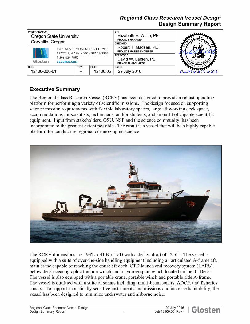
Elizabeth E. White, PE PROJECT MANAGER
CHECKED:
Robert T. Madsen, PE PROJECT MARINE ENGINEER
APPROVED:
David W. Larsen, PE PRINCIPAL-IN-CHARGE
DOC:
12100-000-01 REV:
‒ FILE:
12100.05 DATE:
29 July 2016
Executive Summary
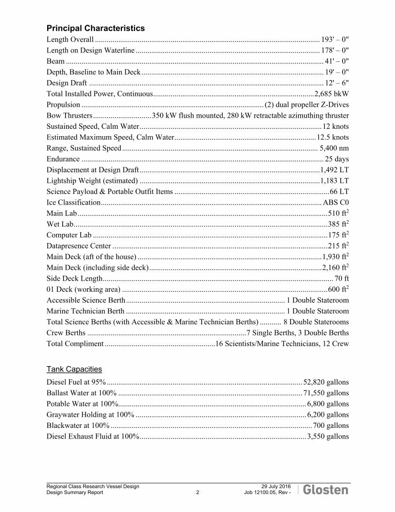
The Regional Class Research Vessel (RCRV) has been designed to provide a robust operating platform for performing a variety of scientific missions. The design focused on supporting science mission requirements with flexible laboratory spaces, large aft working deck space, accommodations for scientists, technicians, and/or students, and an outfit of capable scientific equipment. Input from stakeholders, OSU, NSF and the science community, has been incorporated to the greatest extent possible. The result is a vessel that will be a highly capable platform for conducting regional oceanographic science.
The RCRV dimensions are 193'L x 41'B x 19'D with a design draft of 12'-6". The vessel is equipped with a suite of over-the-side handling equipment including an articulated A-frame aft, main crane capable of reaching the entire aft deck, CTD launch and recovery system (LARS), below deck oceanographic traction winch and a hydrographic winch located on the 01 Deck. The vessel is also equipped with a portable crane, portable winch and portable side A-frame. The vessel is outfitted with a suite of sonars including: multi-beam sonars, ADCP, and fisheries sonars. To support acoustically sensitive instruments and missions and increase habitability, the vessel has been designed to minimize underwater and airborne noise.
Regional Class Research Vessel Design 29 July 2016
Design Summary Report 2 Job 12100.05, Rev -
Principal Characteristics Length Overall .................................................................................................................... 193' – 0"
Length on Design Waterline ............................................................................................... 178' – 0"
Beam ..................................................................................................................................... 41' – 0"
Depth, Baseline to Main Deck .............................................................................................. 19' – 0"
Design Draft ......................................................................................................................... 12' – 6"
Total Installed Power, Continuous ................................................................................... 2,685 bkW
Propulsion .............................................................................................. (2) dual propeller Z-Drives
Bow Thrusters .............................. 350 kW flush mounted, 280 kW retractable azimuthing thruster
Sustained Speed, Calm Water .............................................................................................. 12 knots
Estimated Maximum Speed, Calm Water ......................................................................... 12.5 knots
Range, Sustained Speed ..................................................................................................... 5,400 nm
Endurance ............................................................................................................................. 25 days
Displacement at Design Draft ............................................................................................. 1,492 LT
Lightship Weight (estimated) ............................................................................................. 1,183 LT
Science Payload & Portable Outfit Items ................................................................................ 66 LT
Ice Classification .................................................................................................................. ABS C0
Main Lab ................................................................................................................................. 510 ft2
Wet Lab ................................................................................................................................... 385 ft2
Computer Lab ......................................................................................................................... 175 ft2
Datapresence Center ............................................................................................................... 215 ft2
Main Deck (aft of the house) ............................................................................................... 1,930 ft2
Main Deck (including side deck) ......................................................................................... 2,160 ft2
Side Deck Length ....................................................................................................................... 70 ft
01 Deck (working area) .......................................................................................................... 600 ft2
Accessible Science Berth .................................................................................. 1 Double Stateroom
Marine Technician Berth .................................................................................. 1 Double Stateroom
Total Science Berths (with Accessible & Marine Technician Berths) ........... 8 Double Staterooms
Crew Berths .................................................................................. 7 Single Berths, 3 Double Berths
Total Compliment ......................................................... 16 Scientists/Marine Technicians, 12 Crew
Tank Capacities
Diesel Fuel at 95% ..................................................................................................... 52,820 gallons
Ballast Water at 100% ............................................................................................... 71,550 gallons
Potable Water at 100% ................................................................................................. 6,800 gallons
Graywater Holding at 100% ........................................................................................ 6,200 gallons
Blackwater at 100% ........................................................................................................ 700 gallons
Diesel Exhaust Fluid at 100% ...................................................................................... 3,550 gallons
Regional Class Research Vessel Design 29 July 2016
Design Summary Report 3 Job 12100.05, Rev -
Hull Form
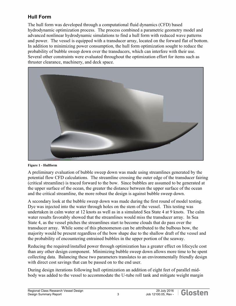
The hull form was developed through a computational fluid dynamics (CFD) based hydrodynamic optimization process. The process combined a parametric geometry model and advanced nonlinear hydrodynamic simulations to find a hull form with reduced wave patterns and power. The vessel is equipped with a transducer array, located on the forward flat of bottom. In addition to minimizing power consumption, the hull form optimization sought to reduce the probability of bubble sweep down over the transducers, which can interfere with their use. Several other constraints were evaluated throughout the optimization effort for items such as thruster clearance, machinery, and deck space.
Figure 1 - Hullform
A preliminary evaluation of bubble sweep down was made using streamlines generated by the potential flow CFD calculations. The streamline crossing the outer edge of the transducer fairing (critical streamline) is traced forward to the bow. Since bubbles are assumed to be generated at the upper surface of the ocean, the greater the distance between the upper surface of the ocean and the critical streamline, the more robust the design is against bubble sweep down.
A secondary look at the bubble sweep down was made during the first round of model testing. Dye was injected into the water through holes on the stem of the vessel. This testing was undertaken in calm water at 12 knots as well as in a simulated Sea State 4 at 9 knots. The calm water results favorably showed that the streamlines would miss the transducer array. In Sea State 4, as the vessel pitches the streamlines start to become clouds that do pass over the transducer array. While some of this phenomenon can be attributed to the bulbous bow, the majority would be present regardless of the bow shape due to the shallow draft of the vessel and the probability of encountering entrained bubbles in the upper portion of the seaway.
Reducing the required/installed power through optimization has a greater effect on lifecycle cost than any other design component. Minimizing bubble sweep down allows more time to be spent collecting data. Balancing these two parameters translates to an environmentally friendly design with direct cost savings that can be passed on to the end user.
During design iterations following hull optimization an addition of eight feet of parallel mid-body was added to the vessel to accommodate the U-tube roll tank and mitigate weight margin
Regional Class Research Vessel Design 29 July 2016
Design Summary Report 4 Job 12100.05, Rev -
risks. A second round of model testing with the lengthened hull was preformed including resistance, propulsion, wake survey and propeller cavitation inception tests.
Arrangements
The RCRV has many mission capabilities similar to larger vessels but in a compact design requiring a highly efficient layout. The Main Deck is designed to provide enhanced accessibility in accordance with the direction given from NSF. Located on the Main Deck are the Main Lab, Wet Lab and Computer Lab as well as the Mess, Galley and a common Lounge. Also located on the Main Deck is a Science Stateroom designed to accommodate an individual with limited mobility.
The 01 Level is outfitted with a Data Presence Center for data collection and ship wide network racks, the remainder of the Science Staterooms, Laundry, and a Hospital. The foredeck of 01 Level is enclosed to provide a sheltered location for the mooring equipment as well as to provide a large open deck area forward on the 02 Level.
The crew staterooms are split between the 1st Platform and the 02 Level. Also located on the 02 Level is a small Gym and a Bridge Electronics Space.
The Pilothouse is designed with enclosed, overhanging, bridge wings and sloped windows for increased over the side visibility. A separate Chart/Radio Room is included in the Pilothouse.
The Pilothouse top provides an unobstructed area for mammal observation activities. The main mast, located on the Pilothouse top is designed to provide an accessible platform for scientific instrumentation.
Science Outfit
As the purpose of this vessel is to provide the science community with a robust platform from which they can conduct their work, considerable effort was expended to optimize the arrangement for the variety of science that could be performed onboard. Accordingly, the vessel includes the following features:
The Main Lab, Wet Lab and Computer Lab are all adjacent resulting in optimal work flow between these spaces. These labs are configured to allow efficient use of the space with open, rectangular floor plans and portable furnishings. This allows for reconfiguration of the spaces as needed.
Space is available in the Transducer Flat and Centerboard for a suite of sonars. The Transducer Flat will house an EM302 0.5 x 1 array as well as the standard suite of fisheries sonars. The Centerboard is designed to have interchangeable shoes allowing for a flexible, easily exchangeable location for additional sonars.
The vessel is outfitted with an oceanographic traction winch located on the 1st Platform. The wire from this winch is led to a flagging sheave mounted near the crane pedestal which allows for ideal wire routing aft through the articulated aft A-frame or out to the end of the crane boom.
The 01 Level winch deck area has been configured to support a range of operations. In the middle of this deck is the hydrographic winch that is typically led to the launch and recovery system. There is additional room on this deck to accommodate a portable winch, similar to the MacArtney Mash 2000 winches currently found in the UNOLS winch pool. This winch could be oriented to lead aft over the A-frame or placed on the Main Deck and oriented to lead to a portable side A-frame located on the starboard side.
Regional Class Research Vessel Design 29 July 2016
Design Summary Report 5 Job 12100.05, Rev -
The entire aft working deck area is clear of non-essential gear and obstructions. On the port side is space and service connections for two 20-foot science vans. At the forward end of the van location is a vestibule to provide sheltered access to the vans from the interior of the house. Services are provided for a third van on the aft working deck. An additional location, forward on the 02 Level, has been designated for a small 10-foot van.
The main working deck, 01 Level winch deck area, and aft 02 Level are all serviceable by the main crane.
A large Science Stores is located directly below the aft working deck. This is easily accessible through a large (60” x 60”), flush, quick-acting, hydraulically operated hatch with the main crane or via internal stairs.
A Meteorological Mast is located on the forward 02 Level. This platform was optimized to ensure clean airflow to the variety of scientific instruments that could be located there.
The vessel is equipped to provide full-time, high speed satellite connectivity for communications, internet access and data transfer including telepresence between researchers afloat and researchers, students and the public ashore.
Maneuverability
With twin Z-drives and two bow thrusters, the vessel is highly maneuverable. The directional stability of the vessel was tested as part of the initial model test program. It was found during these tests that the vessel was not entirely directionally stable, which is normal for a Z-drive vessel. Following the first set of model tests, a flat plate was added to the bottom of the main skeg. The subsequent tests showed an improvement in the vessel’s directional stability. Since that testing took place, the vessel has been lengthened by eight feet and the headboxes, above the Z-drives, were elongated and optimized. The impact on the maneuverability of the vessel of these changes has not been model tested, it is anticipated that these changes may negligibly increase the directional stability of the vessel.
Station Keeping
Having the ability to maintain station over as broad a range of headings as possible is highly desirable. The bow thrusters were sized to be the largest units that could practicably fit in the Bow Thruster Room. The forward bow thruster is a retractable, azimuthing thruster with a maximum developed thrust of at least 5.3 tf. The aft bow thruster is a flush mount, jet-type, azimuthing thruster for use in shallow water, docking and for additional thrust capability when used in conjunction with the retractable thruster. The flush mount thruster has a maximum developed thrust of at least 3.2 tf.
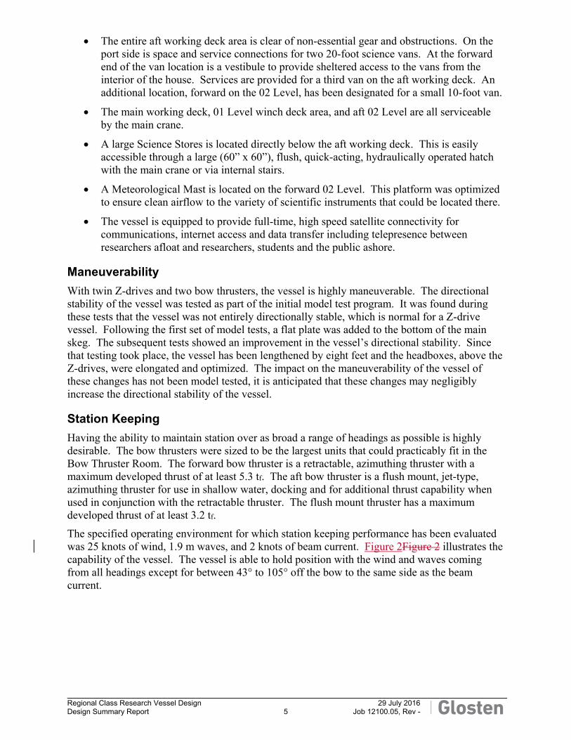
The specified operating environment for which station keeping performance has been evaluated was 25 knots of wind, 1.9 m waves, and 2 knots of beam current. Figure 2Figure 2 illustrates the capability of the vessel. The vessel is able to hold position with the wind and waves coming from all headings except for between 43° to 105° off the bow to the same side as the beam current.
Regional Class Research Vessel Design 29 July 2016
Design Summary Report 6 Job 12100.05, Rev -
Figure 2 - Station keeping capability with 25 knots of wind, 1.8m waves, and 2 knot beam current from starboard.
Vessel Motions
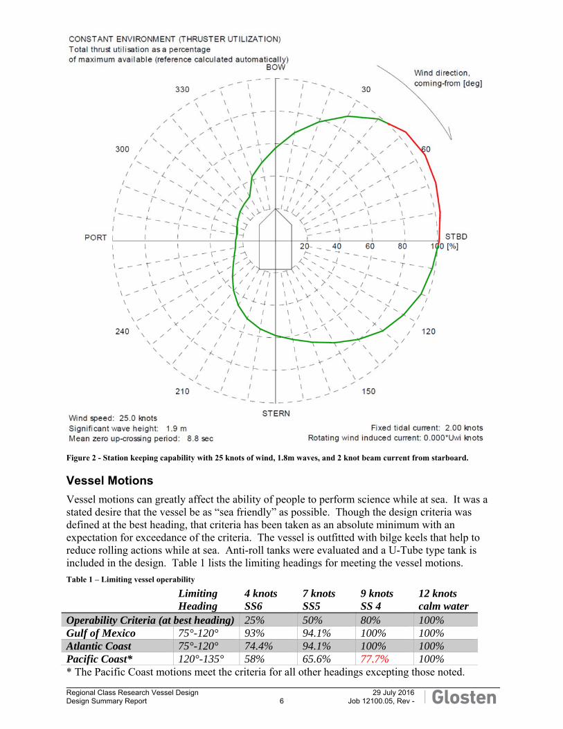
Vessel motions can greatly affect the ability of people to perform science while at sea. It was a stated desire that the vessel be as “sea friendly” as possible. Though the design criteria was defined at the best heading, that criteria has been taken as an absolute minimum with an expectation for exceedance of the criteria. The vessel is outfitted with bilge keels that help to reduce rolling actions while at sea. Anti-roll tanks were evaluated and a U-Tube type tank is included in the design. Table 1 lists the limiting headings for meeting the vessel motions.
Table 1 – Limiting vessel operability
Limiting Heading
4 knots SS6
7 knots SS5
9 knots SS 4
12 knots calm water
Operability Criteria (at best heading) 25% 50% 80% 100% Gulf of Mexico 75°-120° 93% 94.1% 100% 100% Atlantic Coast 75°-120° 74.4% 94.1% 100% 100% Pacific Coast* 120°-135° 58% 65.6% 77.7% 100% * The Pacific Coast motions meet the criteria for all other headings excepting those noted.
Regional Class Research Vessel Design 29 July 2016
Design Summary Report 7 Job 12100.05, Rev -
Structure
The design and specification of the hull and superstructure scantlings and materials are in accordance with ABS Ice Class C0 notation requirements for structural reinforcement and operating temperatures.
The hull of the vessel (Main Deck and below) is designed to be built of steel, with a 24" frame spacing. The framing is primarily transverse with the exception of the Main Deck which is longitudinally framed to better accommodate large deck loads and the deck socket grid. The superstructure (above Main Deck to 01 Level) is also designed to be built of steel and is transversely framed with 24" frame spacing.
The superstructure above the 01 Level is designed to be constructed of aluminum and is transversely framed with a 24" frame spacing. Aluminum plating is to be either 5083 or 5086 alloys and shapes shall be 6061-T6. The aluminum deckhouse is to be attached to the steel 01 Level deck via Detacouple 9009 consisting of 5083 or 5086 aluminum and steel.
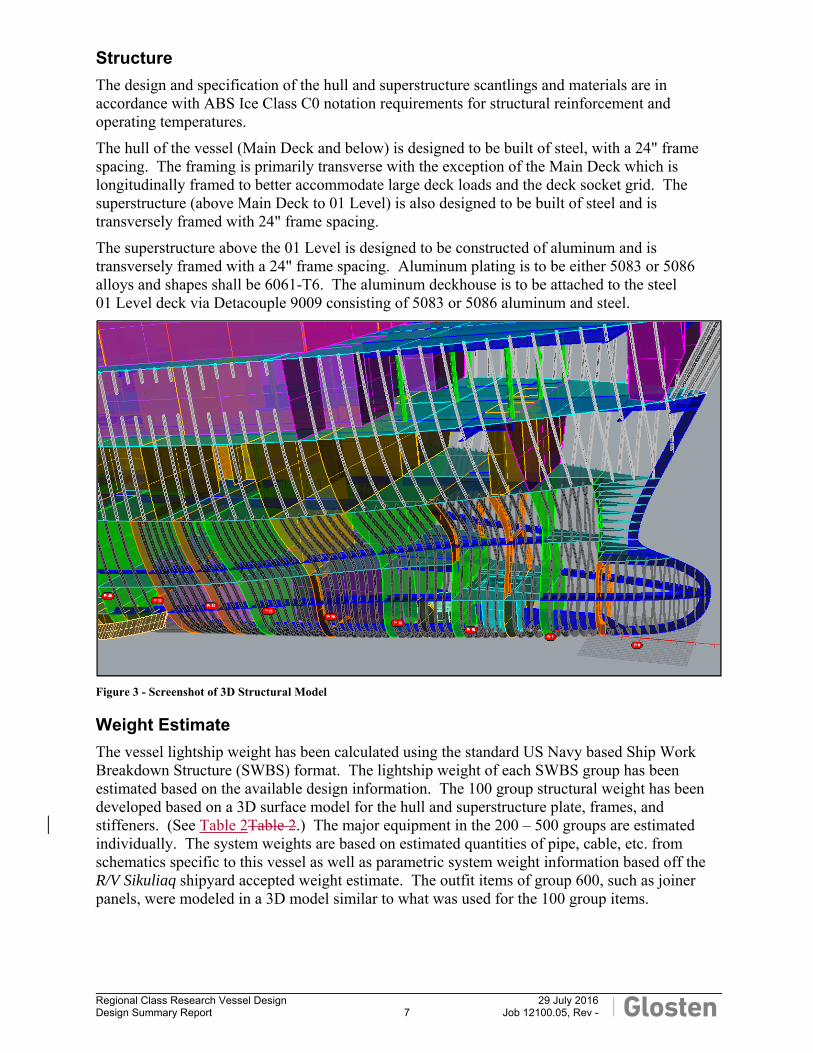
Figure 3 - Screenshot of 3D Structural Model
Weight Estimate
The vessel lightship weight has been calculated using the standard US Navy based Ship Work Breakdown Structure (SWBS) format. The lightship weight of each SWBS group has been estimated based on the available design information. The 100 group structural weight has been developed based on a 3D surface model for the hull and superstructure plate, frames, and stiffeners. (See Table 2Table 2.) The major equipment in the 200 – 500 groups are estimated individually. The system weights are based on estimated quantities of pipe, cable, etc. from schematics specific to this vessel as well as parametric system weight information based off the R/V Sikuliaq shipyard accepted weight estimate. The outfit items of group 600, such as joiner panels, were modeled in a 3D model similar to what was used for the 100 group items.
Regional Class Research Vessel Design 29 July 2016
Design Summary Report 8 Job 12100.05, Rev -
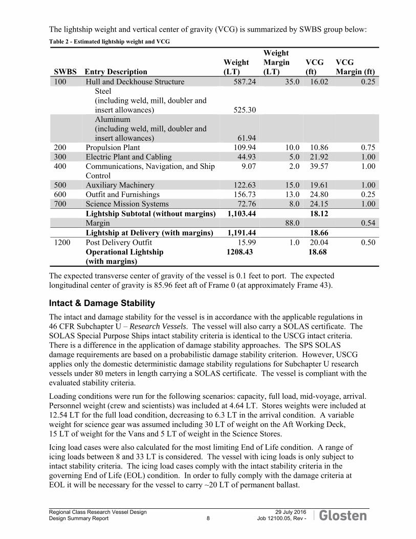
The lightship weight and vertical center of gravity (VCG) is summarized by SWBS group below:
Table 2 - Estimated lightship weight and VCG
SWBS Entry Description Weight (LT)
Weight Margin (LT)
VCG (ft)
VCG Margin (ft)
100 Hull and Deckhouse Structure 587.24 35.0 16.02 0.25
Steel (including weld, mill, doubler and insert allowances) 525.30
Aluminum (including weld, mill, doubler and insert allowances) 61.94
200 Propulsion Plant 109.94 10.0 10.86 0.75300 Electric Plant and Cabling 44.93 5.0 21.92 1.00400 Communications, Navigation, and Ship
Control 9.07 2.0 39.57 1.00
500 Auxiliary Machinery 122.63 15.0 19.61 1.00600 Outfit and Furnishings 156.73 13.0 24.80 0.25700 Science Mission Systems 72.76 8.0 24.15 1.00 Lightship Subtotal (without margins) 1,103.44 18.12 Margin 88.0 0.54 Lightship at Delivery (with margins) 1,191.44 18.66 1200 Post Delivery Outfit 15.99 1.0 20.04 0.50
Operational Lightship (with margins)
1208.43 18.68
The expected transverse center of gravity of the vessel is 0.1 feet to port. The expected longitudinal center of gravity is 85.96 feet aft of Frame 0 (at approximately Frame 43).
Intact & Damage Stability
The intact and damage stability for the vessel is in accordance with the applicable regulations in 46 CFR Subchapter U – Research Vessels. The vessel will also carry a SOLAS certificate. The SOLAS Special Purpose Ships intact stability criteria is identical to the USCG intact criteria. There is a difference in the application of damage stability approaches. The SPS SOLAS damage requirements are based on a probabilistic damage stability criterion. However, USCG applies only the domestic deterministic damage stability regulations for Subchapter U research vessels under 80 meters in length carrying a SOLAS certificate. The vessel is compliant with the evaluated stability criteria.
Loading conditions were run for the following scenarios: capacity, full load, mid-voyage, arrival. Personnel weight (crew and scientists) was included at 4.64 LT. Stores weights were included at 12.54 LT for the full load condition, decreasing to 6.3 LT in the arrival condition. A variable weight for science gear was assumed including 30 LT of weight on the Aft Working Deck, 15 LT of weight for the Vans and 5 LT of weight in the Science Stores.
Icing load cases were also calculated for the most limiting End of Life condition. A range of icing loads between 8 and 33 LT is considered. The vessel with icing loads is only subject to intact stability criteria. The icing load cases comply with the intact stability criteria in the governing End of Life (EOL) condition. In order to fully comply with the damage criteria at EOL it will be necessary for the vessel to carry ~20 LT of permanent ballast.
Regional Class Research Vessel Design 29 July 2016
Design Summary Report 9 Job 12100.05, Rev -
Tonnage
The calculated international gross tonnage for the vessel is approximately 1,400 tons.
Propulsion System/Power Generation
The propulsion system is designed to provide maximum capability within the mission requirements and physical constraints of the design. Design considerations included speed and power, maneuverability, station keeping, reliability, flexibility, and efficiency.
The selected propulsion system configuration is an integrated diesel-electric system with twin azimuthing Z-drives and two azimuthing bow thrusters. The details of the equipment are listed in the table below. The design of the propulsion system was developed in close coordination with the integrated electrical plant design.
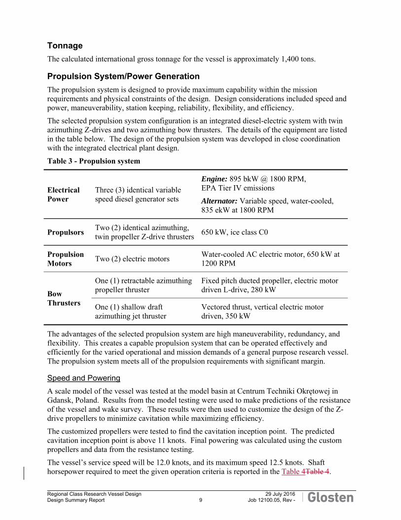
Table 3 - Propulsion system
Electrical Power
Three (3) identical variable speed diesel generator sets
Engine: 895 bkW @ 1800 RPM, EPA Tier IV emissions
Alternator: Variable speed, water-cooled, 835 ekW at 1800 RPM
Propulsors Two (2) identical azimuthing, twin propeller Z-drive thrusters
650 kW, ice class C0
Propulsion Motors
Two (2) electric motors Water-cooled AC electric motor, 650 kW at 1200 RPM
Bow Thrusters
One (1) retractable azimuthing propeller thruster
Fixed pitch ducted propeller, electric motor driven L-drive, 280 kW
One (1) shallow draft azimuthing jet thruster
Vectored thrust, vertical electric motor driven, 350 kW
The advantages of the selected propulsion system are high maneuverability, redundancy, and flexibility. This creates a capable propulsion system that can be operated effectively and efficiently for the varied operational and mission demands of a general purpose research vessel. The propulsion system meets all of the propulsion requirements with significant margin.
Speed and Powering
A scale model of the vessel was tested at the model basin at Centrum Techniki Okrętowej in Gdansk, Poland. Results from the model testing were used to make predictions of the resistance of the vessel and wake survey. These results were then used to customize the design of the Z-drive propellers to minimize cavitation while maximizing efficiency.
The customized propellers were tested to find the cavitation inception point. The predicted cavitation inception point is above 11 knots. Final powering was calculated using the custom propellers and data from the resistance testing.
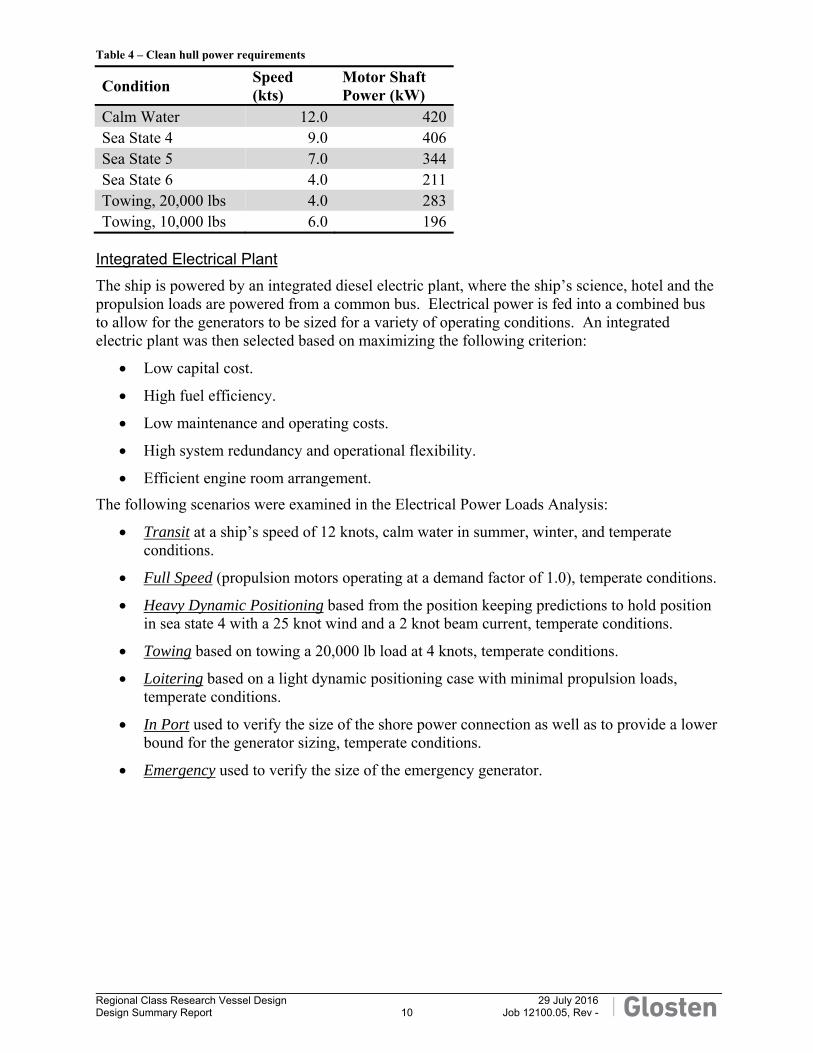
The vessel’s service speed will be 12.0 knots, and its maximum speed 12.5 knots. Shaft horsepower required to meet the given operation criteria is reported in the Table 4Table 4.
Regional Class Research Vessel Design 29 July 2016
Design Summary Report 10 Job 12100.05, Rev -
Table 4 – Clean hull power requirements
Condition Speed (kts)
Motor Shaft Power (kW)
Calm Water 12.0 420Sea State 4 9.0 406Sea State 5 7.0 344Sea State 6 4.0 211Towing, 20,000 lbs 4.0 283Towing, 10,000 lbs 6.0 196
Integrated Electrical Plant
The ship is powered by an integrated diesel electric plant, where the ship’s science, hotel and the propulsion loads are powered from a common bus. Electrical power is fed into a combined bus to allow for the generators to be sized for a variety of operating conditions. An integrated electric plant was then selected based on maximizing the following criterion:
Low capital cost.
High fuel efficiency.
Low maintenance and operating costs.
High system redundancy and operational flexibility.
Efficient engine room arrangement.
The following scenarios were examined in the Electrical Power Loads Analysis:
Transit at a ship’s speed of 12 knots, calm water in summer, winter, and temperate conditions.
Full Speed (propulsion motors operating at a demand factor of 1.0), temperate conditions.
Heavy Dynamic Positioning based from the position keeping predictions to hold position in sea state 4 with a 25 knot wind and a 2 knot beam current, temperate conditions.
Towing based on towing a 20,000 lb load at 4 knots, temperate conditions.
Loitering based on a light dynamic positioning case with minimal propulsion loads, temperate conditions.
In Port used to verify the size of the shore power connection as well as to provide a lower bound for the generator sizing, temperate conditions.
Emergency used to verify the size of the emergency generator.
Regional Class Research Vessel Design 29 July 2016
Design Summary Report 11 Job 12100.05, Rev -
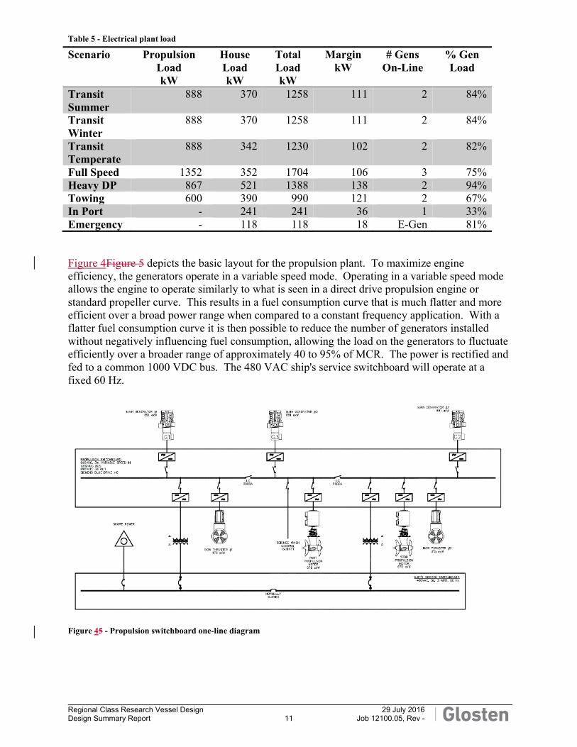
Table 5 - Electrical plant load
Scenario Propulsion Load kW
House Load kW
Total Load kW
Margin kW
# Gens On-Line
% Gen Load
Transit Summer
888 370 1258 111 2 84%
Transit Winter
888 370 1258 111 2 84%
Transit Temperate
888 342 1230 102 2 82%
Full Speed 1352 352 1704 106 3 75%Heavy DP 867 521 1388 138 2 94%Towing 600 390 990 121 2 67%In Port - 241 241 36 1 33%Emergency - 118 118 18 E-Gen 81%
Figure 4Figure 5 depicts the basic layout for the propulsion plant. To maximize engine efficiency, the generators operate in a variable speed mode. Operating in a variable speed mode allows the engine to operate similarly to what is seen in a direct drive propulsion engine or standard propeller curve. This results in a fuel consumption curve that is much flatter and more efficient over a broad power range when compared to a constant frequency application. With a flatter fuel consumption curve it is then possible to reduce the number of generators installed without negatively influencing fuel consumption, allowing the load on the generators to fluctuate efficiently over a broader range of approximately 40 to 95% of MCR. The power is rectified and fed to a common 1000 VDC bus. The 480 VAC ship's service switchboard will operate at a fixed 60 Hz.
Figure 45 - Propulsion switchboard one-line diagram
Regional Class Research Vessel Design 29 July 2016
Design Summary Report 12 Job 12100.05, Rev -
Green Ship Initiatives
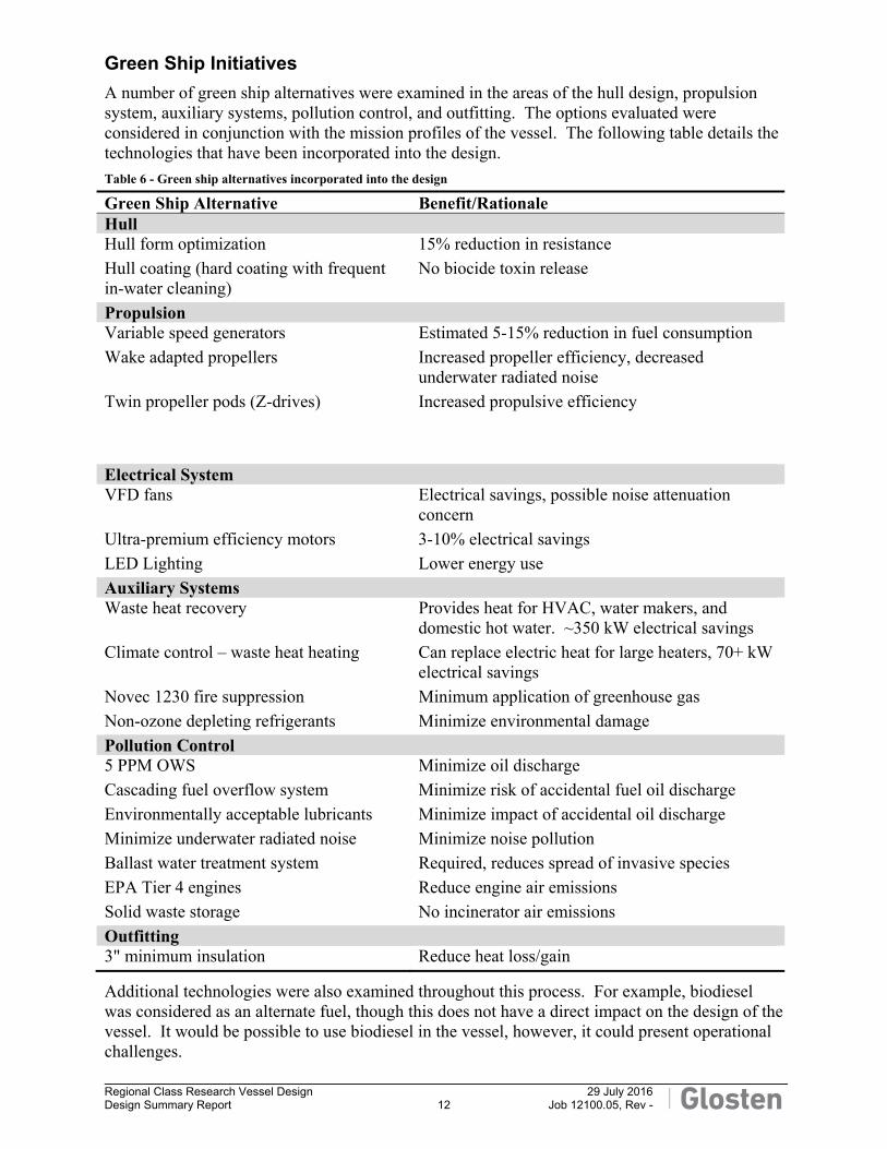
A number of green ship alternatives were examined in the areas of the hull design, propulsion system, auxiliary systems, pollution control, and outfitting. The options evaluated were considered in conjunction with the mission profiles of the vessel. The following table details the technologies that have been incorporated into the design.
Table 6 - Green ship alternatives incorporated into the design
Green Ship Alternative Benefit/Rationale Hull Hull form optimization 15% reduction in resistance
Hull coating (hard coating with frequent in-water cleaning)
No biocide toxin release
Propulsion Variable speed generators Estimated 5-15% reduction in fuel consumption
Wake adapted propellers Increased propeller efficiency, decreased underwater radiated noise
Twin propeller pods (Z-drives) Increased propulsive efficiency
Electrical System VFD fans Electrical savings, possible noise attenuation
concern
Ultra-premium efficiency motors 3-10% electrical savings
LED Lighting Lower energy use
Auxiliary Systems Waste heat recovery Provides heat for HVAC, water makers, and
domestic hot water. ~350 kW electrical savings
Climate control – waste heat heating Can replace electric heat for large heaters, 70+ kW electrical savings
Novec 1230 fire suppression Minimum application of greenhouse gas
Non-ozone depleting refrigerants Minimize environmental damage
Pollution Control 5 PPM OWS Minimize oil discharge
Cascading fuel overflow system Minimize risk of accidental fuel oil discharge
Environmentally acceptable lubricants Minimize impact of accidental oil discharge
Minimize underwater radiated noise Minimize noise pollution
Ballast water treatment system Required, reduces spread of invasive species
EPA Tier 4 engines Reduce engine air emissions
Solid waste storage No incinerator air emissions
Outfitting 3" minimum insulation Reduce heat loss/gain
Additional technologies were also examined throughout this process. For example, biodiesel was considered as an alternate fuel, though this does not have a direct impact on the design of the vessel. It would be possible to use biodiesel in the vessel, however, it could present operational challenges.
Regional Class Research Vessel Design 29 July 2016
Design Summary Report 13 Job 12100.05, Rev -
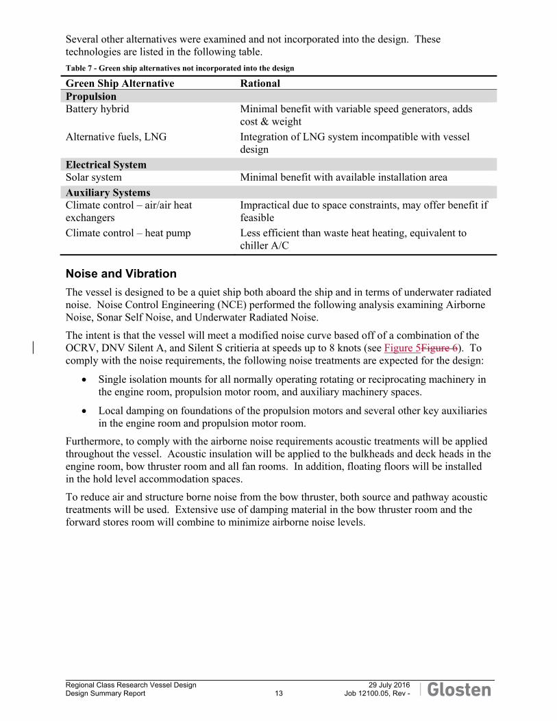
Several other alternatives were examined and not incorporated into the design. These technologies are listed in the following table.
Table 7 - Green ship alternatives not incorporated into the design
Green Ship Alternative Rational Propulsion Battery hybrid Minimal benefit with variable speed generators, adds
cost & weight
Alternative fuels, LNG Integration of LNG system incompatible with vessel design
Electrical System Solar system Minimal benefit with available installation area
Auxiliary Systems Climate control – air/air heat exchangers
Impractical due to space constraints, may offer benefit if feasible
Climate control – heat pump Less efficient than waste heat heating, equivalent to chiller A/C
Noise and Vibration
The vessel is designed to be a quiet ship both aboard the ship and in terms of underwater radiated noise. Noise Control Engineering (NCE) performed the following analysis examining Airborne Noise, Sonar Self Noise, and Underwater Radiated Noise.
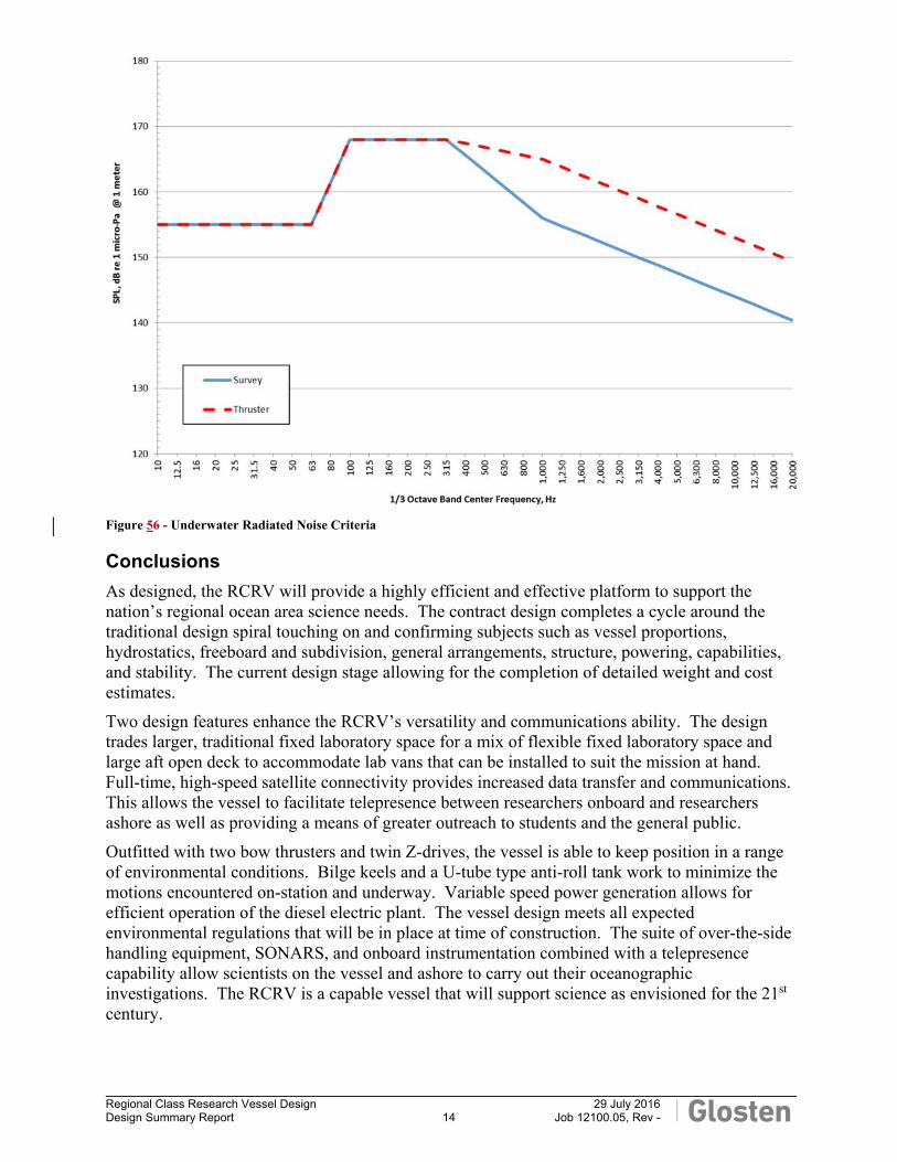
The intent is that the vessel will meet a modified noise curve based off of a combination of the OCRV, DNV Silent A, and Silent S critieria at speeds up to 8 knots (see Figure 5Figure 6). To comply with the noise requirements, the following noise treatments are expected for the design:
Single isolation mounts for all normally operating rotating or reciprocating machinery in the engine room, propulsion motor room, and auxiliary machinery spaces.
Local damping on foundations of the propulsion motors and several other key auxiliaries in the engine room and propulsion motor room.
Furthermore, to comply with the airborne noise requirements acoustic treatments will be applied throughout the vessel. Acoustic insulation will be applied to the bulkheads and deck heads in the engine room, bow thruster room and all fan rooms. In addition, floating floors will be installed in the hold level accommodation spaces.
To reduce air and structure borne noise from the bow thruster, both source and pathway acoustic treatments will be used. Extensive use of damping material in the bow thruster room and the forward stores room will combine to minimize airborne noise levels.
Regional Class Research Vessel Design 29 July 2016
Design Summary Report 14 Job 12100.05, Rev -
Figure 56 - Underwater Radiated Noise Criteria
Conclusions
As designed, the RCRV will provide a highly efficient and effective platform to support the nation’s regional ocean area science needs. The contract design completes a cycle around the traditional design spiral touching on and confirming subjects such as vessel proportions, hydrostatics, freeboard and subdivision, general arrangements, structure, powering, capabilities, and stability. The current design stage allowing for the completion of detailed weight and cost estimates.
Two design features enhance the RCRV’s versatility and communications ability. The design trades larger, traditional fixed laboratory space for a mix of flexible fixed laboratory space and large aft open deck to accommodate lab vans that can be installed to suit the mission at hand. Full-time, high-speed satellite connectivity provides increased data transfer and communications. This allows the vessel to facilitate telepresence between researchers onboard and researchers ashore as well as providing a means of greater outreach to students and the general public.
Outfitted with two bow thrusters and twin Z-drives, the vessel is able to keep position in a range of environmental conditions. Bilge keels and a U-tube type anti-roll tank work to minimize the motions encountered on-station and underway. Variable speed power generation allows for efficient operation of the diesel electric plant. The vessel design meets all expected environmental regulations that will be in place at time of construction. The suite of over-the-side handling equipment, SONARS, and onboard instrumentation combined with a telepresence capability allow scientists on the vessel and ashore to carry out their oceanographic investigations. The RCRV is a capable vessel that will support science as envisioned for the 21st century.
Regional Class Research Vessel Design 29 July 2016
Design Summary Report 15 Job 12100.05, Rev -