design test report report no. eu1589-h-01 mvn … 1.2/50 impulse test was performed under dry...
TRANSCRIPT

Design Test Report
Report No. EU1589-H-01 MVN Series Porcelain-housed Arrester
This report records the results of type tests made on MVN series arresters, rated up to 444 kV (353 kV MCOV). Tests were performed in accordance with procedures of IEEE Std C62.11-2012, “IEEE Standard for Metal-Oxide Surge arresters for AC Power Circuits (>1 kV)”. To the best of our knowledge and within the usual limits of testing practice, tests performed on these arresters demonstrate compliance with the relevant clauses of the referenced standard. Michael Kelley Chris Kulig Senior Technology Manager Senior Design Engineer
Date: 11/15/13
Separate reports provide details of each test, according to the following table: Report No. Description Clause Issue date
EU1589-H-01.1 Arrester Insulation withstand 8.1 11/15/13 EU1589-H-02.1 Discharge voltage characteristics 8.2 11/15/13 EU1589-H-03.1 Accelerated aging of MOV blocks 8.5 11/15/13 EU1589-H-04.1 Contamination 8.8 11/15/13 EU1589-H-05.1 Radio-influence voltage (RIV) 8.10 11/15/13 EU1589-H-06.1 Partial discharge (PD) 8.11 11/15/13 EU1589-H-13 Switching surge energy rating 8.14 11/15/13 EU1589-H-14 Single-impulse withstand rating 8.15 11/15/13 EU1589-H-09.1 Duty cycle 8.16 11/15/13 EU1589-H-10.1 Temporary overvoltage (TOV) 8.17 11/15/13 EU1589-H-12.1 Short Circuit 8.18 11/15/13 EU1589-H-11.1 Ultimate mechanical strength-static 8.23 11/15/13

Design Test Report Report No. EU1589-H-01.1
MVN Series Porcelain-housed Arrester
Arrester Insulation Withstand Test
This report records the results of type tests made on MVN series arresters, rated up to 444 kV (353 kV MCOV). Tests were performed in accordance with procedures of IEEE Std C62.11-2012, “IEEE Standard for Metal-Oxide Surge arresters for AC Power Circuits (>1 kV)”. To the best of our knowledge and within the usual limits of testing practice, tests performed on these arresters demonstrate compliance with the relevant clauses of the referenced standard. Michael Kelley Chris Kulig Senior Technology Manager Senior Design Engineer
Date: 11/15/13

EU1589-H-01.1
- 2 -
DESIGN TEST REPORT Arrester Insulation Withstand Test
TESTS PERFORMED: Insulation withstand tests were made on one arrester unit of each length used in MVN arresters, in accordance with the requirements of Clause 8.1 of IEEE C62.11-2012. The internal components of the units were removed for these tests. It is required that the external insulation withstand of the arrester housing conforms to the following:
• The 1.2/50 impulse withstand voltage in dry conditions shall not be less than the maximum discharge voltage for a 20 kA 8/20 discharge current multiplied by 1.42.
• The 10 s wet power frequency withstand voltage (rms value) shall not be less than the maximum switching impulse discharge voltage multiplied by 0.82.
For purposes of evaluation, the highest unit MCOV used for each of the four unit lengths will be used as the basis for the discharge voltages. These are as listed in Table 1.
Table 1. Parameters of tested housing units
Housing number
Overall unit length
(with fittings)
Dry arc distance
Leakage distance
Highest MCOV used in housing
Max. 20kA 8/20 discharge voltage
Max. 2kA
switching impulse
discharge voltage
mm mm mm kVrms kVcr kVcr 0 663 445 1116 45 154 115 1 826 616 1905 59 202 151 2 978 768 2540 81 277 207 3 1143 940 3207 98 335 251 4 1308 1099 3874 115 393 294
RESULTS: 1.2/50 impulse The 1.2/50 impulse test was performed under dry conditions by applying 15 positive and 15 negative full-wave lightning-impulse voltages to the test samples, according to the requirements of Clause 7.8.2.2 of IEEE 4-1995. The impulse voltages had a virtual front time of 1.2 µs (±30%) and a virtual time to half value of 50 µs (±20%). The test samples withstood the applied voltages without disruptive discharge. The withstand voltages obtained were corrected to standard atmospheric conditions in accordance with IEEE 4. In all cases, the positive polarity impulses resulted in the lower withstand voltage. The corrected positive withstand values are reported in Table 2.

EU1589-H-01.1
- 3 -
Table 2. 1.2/50 impulse withstand results
Housing number
Measured withstand
voltage
Ambient temperature
Barometric pressure
Absolute humidity Air density
correction factor
kd
Humidity correction
factor kh
Voltage correction
factor K = kd/kh
Corrected withstand voltage
kVpk oC kPa g.m-3 kVpk
p.u. of 20kA 8/20 discharge
voltage 0 249 20.9 97.7 3.24 0.961 1.069 0.899 276 1.79 1 320 20.9 97.7 3.24 0.961 1.069 0.899 355 1.75 2 392 20.9 97.7 3.24 0.961 1.069 0.899 436 1.57 3 462 21.2 97.7 3.30 0.962 1.067 0.902 512 1.52 4 548 21.2 97.7 3.30 0.962 1.067 0.902 607 1.54
Power frequency The power frequency test was performed under wet conditions by applying a 60 Hz voltage for a duration of at least 10 s. The test samples withstood the applied voltages without disruptive discharge. The withstand voltages obtained were corrected to standard atmospheric conditions in accordance with IEEE 4. The withstand values are reported in Table 3.
Table 3. Power frequency withstand results
Housing number
Measured withstand
voltage
Ambient temperature
Barometric pressure
Absolute humidity Air density
correction factor
kd
Humidity correction
factor kh
Voltage correction
factor K = kd/kh
Corrected withstand voltage
kVrms oC kPa g.m-3 kVrms
p.u. of 2kA SS
discharge voltage
0 106 20.9 96.5 2.47 0.961 1.000 0.961 110 0.95 1 155 20.9 96.5 2.47 0.961 1.000 0.961 161 1.06 2 208 20.9 96.5 2.47 0.961 1.000 0.961 216 1.04 3 289 21.2 97.8 5.10 0.962 1.000 0.962 300 1.19 4 339 21.2 97.8 5.10 0.962 1.000 0.962 352 1.19
EVALUATION: The voltage withstand for 1.2/50 impulse under dry conditions and for power frequency voltage under wet conditions exceed the minimum requirements and therefore the MVN design meets the arrester insulation withstand test requirements of IEEE C62.11-2012.

1
Design Test Report Report No. EU1589-H-02.1
MVN Series Porcelain-housed Arrester
Discharge Voltage Characteristics
This report records the results of type tests made on MVN series arresters, rated up to 444 kV (353 kV MCOV). Tests were performed in accordance with procedures of IEEE Std C62.11-2012, “IEEE Standard for Metal-Oxide Surge arresters for AC Power Circuits (>1 kV)”. To the best of our knowledge and within the usual limits of testing practice, tests performed on these arresters demonstrate compliance with the relevant clauses of the referenced standard. Michael Kelley Chris Kulig Senior Technology Manager Senior Design Engineer
Date: 11/15/13
EU1589-H-02.1
2
DESIGN TEST REPORT Discharge Voltage Characteristics
TESTS PERFORMED: Discharge voltage measurements were made on three single MOV blocks of the longest length of the type used in MVN arresters. Tests were conducted in accordance with Clause 8.3 of IEEE C62.11-2012, to determine discharge voltage-current and voltage-time characteristics. Lightning impulse discharge voltages were determined for 8/20 impulse currents of 1500 A, 3000 A, 5000 A, 10 000 A, 20 000 A and 40 000 A. Switching impulse discharge voltages were determined for 0.25, 0.5, 1, 2, and 3kA with impulse wave shape of 36/90. Front-of-wave (FOW) discharge voltages were determined for 10 kA and 20 kA impulses with virtual front time of 1 µs. All discharge voltages measured during the design tests have been normalized to the voltage measured for the current used for routine tests on production MVN arresters, namely 10kA 8/20. RESULTS: Lightning impulse discharge voltage Table 1 shows the discharge voltages measured at different currents on the three test samples. For each test sample, the measured discharge voltages have been normalized to the voltage measured at 10 kA, 8/20, the current magnitude and wave shape used for routine tests on production MVN arresters.
Table 1. Discharge voltage-current measurements for 8/20 current wave shape (lightning impulse)
Current Sample 1 Sample 2 Sample 3
kAcr kVcr Normalized
p.u. kVcr Normalized
p.u. kVcr Normalized
p.u. 1.5 11.935 0.873 11.935 0.871 11.944 0.873 3 12.446 0.910 12.455 0.909 12.455 0.910 5 12.936 0.946 12.936 0.945 12.915 0.944 10 13.679 1.000 13.696 1.000 13.687 1.000 20 14.672 1.073 14.664 1.071 14.638 1.069 40 16.207 1.185 16.102 1.176 16.144 1.180
Switching impulse discharge voltage Table 2 shows the discharge voltages measured for 0.25, 0.5, 1, 2 and 3 kA impulses with 36/90 waveshape. For each test sample, the measured discharge voltages have been normalized to the voltage measured at 10 kA, 8/20, the current magnitude and waveshape used for routine tests on production MVN arresters.

EU1589-H-02.1
3
Table 2. Discharge voltages for 36/90 waveshape (switching impulse)
Current Sample 1 Sample 2 Sample 3
kAcr kVcr Normalized
p.u. kVcr Normalized
p.u. kVcr Normalized
p.u. 0.25 11.031 0.806 11.023 0.805 11.023 0.805 0.5 11.284 0.825 11.292 0.824 11.309 0.826 1 11.628 0.850 11.620 0.848 11.637 0.850
1.5 11.821 0.864 11.837 0.864 11.854 0.866 2 12.077 0.883 12.044 0.879 12.065 0.881 3 12.325 0.901 12.325 0.900 12.346 0.902
Front-of wave (FOW) discharge voltage Table 3 shows the discharge voltages measured for 10 kA and 20 kA impulses with virtual front time of 1 µs. For each test sample, the measured discharge voltages have been normalized to the voltage measured at 10 kA, 8/20, the current magnitude and waveshape used for routine tests on production MVN arresters.
Table 3. Discharge voltages for 1/2 waveshape (front-of-wave)
Current Sample 1 Sample 2 Sample 3 kAcr kVcr p.u. kVcr p.u. kVcr p.u. 10 14.609 1.068 14.609 1.067 14.597 1.066 20 15.814 1.156 15.827 1.156 15.852 1.158

EU1589-H-02.1
4
Figure 1. Measured discharge voltage-current characteristics normalized to discharge current of 10kA 8/20
Evaluation In the routine tests of production MVN arresters, discharge voltages are performed at 10 kA, 8/20. If the maximum permitted value for this voltage for a given rating of arrester is represented by discharge-voltageroutinetestmax, and the maximum published discharge value for any given magnitude and waveshape of current is represented by discharge-voltagepublishedmax then the “production test ratio” for that discharge current magnitude and waveshape is given by production-test ratio = discharge-voltagepublishedmax / discharge-voltageroutinetestmax For all arresters in the MVN family, the normalized discharge voltages determined from design tests (given in Tables 1 – 3) are less than the production-test ratio for each of the corresponding currents. As an example, Table 4 shows the evaluation for an MVN with 98 kV MCOV (120 kV duty cycle rated voltage). In all instances, the normalized design test values are less than the production-test ratio, thereby meeting the requirements specified in IEEE C62.11-2012.

EU1589-H-02.1
5
Table 4 – Evaluation of discharge voltage design tests for 98 kV MCOV MVN
arrester
discharge-voltageroutinetestmax = 281.5 kV
The normalized values presented in Tables 1 – 3 are shown graphically in Figure 1. These values (per-unit discharge-voltagechart) are used to calculate the discharge voltage characteristics (discharge-voltagearrester) of assembled MVN arresters, as follows:
discharge-voltagearrester = per-unit discharge-voltagechart x discharge-voltage10kA pub where discharge-voltage10kA pub is the published maximum discharge voltage of the arrester for 10kA 8/20, as verified by routine test at time of arrester manufacture.

Design Test Report Report No. EU1589-H-03.1
MVN Series Porcelain-housed Arrester
Accelerated Aging Procedure
This report records the results of type tests made on MVN series arresters, rated up to 444 kV (353 kV MCOV). Tests were performed in accordance with procedures of IEEE Std C62.11-2012, “IEEE Standard for Metal-Oxide Surge arresters for AC Power Circuits (>1 kV)”. To the best of our knowledge and within the usual limits of testing practice, tests performed on these arresters demonstrate compliance with the relevant clauses of the referenced standard. Michael Kelley Chris Kulig Senior Technology Manager Senior Design Engineer
Date: 11/15/13

EU1589-H-03.1
- 2 -
DESIGN TEST REPORT Accelerated Aging Procedure
TESTS PERFORMED: Accelerated aging tests were performed at 15% above MCOV on three MOV blocks of the shortest length used in MVN arresters and on three MOV blocks of the longest length used in MVN arresters. The tests were conducted in accordance with the requirements of Clause 8.5 of IEEE C62.11-2012. The test samples were placed in an air oven and energized at a voltage equal to an adjusted MCOV that accounts for the maximum non-uniformity of voltage distribution in arrester application. The temperature of the samples was maintained at 115 °C ± 2 °C for the duration of the test. Power dissipation was measured on each sample at the adjusted MCOV and at duty-cycle voltage 2 h after the start of the 1000 h test period, and again at the end of the period. RESULTS: Power dissipation measured after two hours and after 1000 hours on the six MOV block samples are reported in Table 1.
Table 1. Accelerated aging test data
MOV block size Sample number
Power dissipation at adjusted MCOV (W)
Power dissipation at duty-
cycle voltage (W)
After 2 h After 1000 h After 2 h After 1000 h
Shortest 1 2.39 2.09 3.80 3.38 2 2.71 2.24 4.64 4.43 3 2.47 2.00 4.43 3.68
Longest 1 4.03 3.43 7.23 6.39 2 3.73 3.10 7.18 6.07 3 3.42 2.94 6.19 5.19
EVALUATION: The values of power dissipation at the end of the 1000-hour test period were, in all cases, less than the values at 2 hours. Consequently, no adjustment to test sample MCOV and duty-cycle voltage is required for low-current long-duration, high-current short-duration, duty cycle, and TOV tests (i.e. accelerated aging adjustment factors kC and kR are both equal to 1.00).
Design Test Report Report No. EU1589-H-04.1
MVN Series Porcelain-housed Arrester
Contamination Test
This report records the results of type tests made on MVN series arresters, rated up to 444 kV (353 kV MCOV). Tests were performed in accordance with procedures of IEEE Std C62.11-2012, “IEEE Standard for Metal-Oxide Surge arresters for AC Power Circuits (>1 kV)”. To the best of our knowledge and within the usual limits of testing practice, tests performed on these arresters demonstrate compliance with the relevant clauses of the referenced standard. Michael Kelley Chris Kulig Senior Technology Manager Senior Design Engineer
Date: 11/15/13

EU1589-H-04.1
- 2 -
DESIGN TEST REPORT Contamination Test
TESTS PERFORMED: A fully-assembled arrester, with MCOV of 353 kV was subjected to the contamination test as prescribed in Clause 8.8 of IEEE C62.11-2012. The arrester was energized at MCOV for 1 hour, at which time the power loss was measured. The arrester was de-energized for application of the contaminant slurry. The contaminant consisted of water, bentonite (at concentration of 5g/L of water), a non-ionic detergent (at concentration of 1 g/L of water), and sodium chloride sufficient to bring the resistivity of the slurry to 435 Ω.cm. The slurry was flowed as uniformly as possible over all housing surfaces of the lower 50% of the arrester (the complete bottom unit and half-way up the second unit). The contaminant application and re-energization at MCOV was accomplished within 7-8 minutes from the time of the de-energization. Power losses were measured at time of re-energization and at times 1, 5, 10 and 15 minutes thereafter. At the 15 minute mark, the arrester was de-energized, upon which the process of contaminant application and subsequent re-energization at MCOV for 15 minutes, and power loss measurement during the 15 minute period was repeated. At the end of this second cycle, MCOV was maintained for an additional 30 minutes, during which time power loss was measured. RESULTS: Figure 1 shows the arrester installed for test. Figure 2 shows a close up view during the application of contaminant to the bottom two units.
Figure 1. Arrester ready for test Figure 2. Units during contamination

EU1589-H-04.1
- 3 -
The following table lists the power loss measurements made at each stage of the test.
Stage
Time of day Elapsed time in stage
Power loss
hh:mm min W
Initial energization
13:45 0 99 14:00 15 100 14:15 30 96 14:30 45 101 14:45 60 103
First contaminant application
14:52 0 140 14:53 1 152 14:57 5 126 15:02 10 126 15:07 15 126
Second contaminant application
15:15 0 669 15:16 1 567 15:20 5 486 15:25 10 186 15:30 15 158
Recovery
15:30 0 158 15:35 5 149 15:40 10 142 15:45 15 142 15:50 20 134 15:55 25 134 16:00 30 126
EVALUATION The design meets the contamination test requirements of IEEE C62.11-2012. The power loss increased substantially with the application of contaminant, but steadily decreased with time. At the end of the 30 minute recovery period the power loss was approaching the value at the start of the test prior to contamination.

Design Test Report Report No. EU1589-H-05.1
MVN Series Porcelain-housed Arrester
Radio Influence Voltage (RIV)
This report records the results of type tests made on MVN series arresters, rated up to 444 kV (353 kV MCOV). Tests were performed in accordance with procedures of IEEE Std C62.11-2012, “IEEE Standard for Metal-Oxide Surge arresters for AC Power Circuits (>1 kV)”. To the best of our knowledge and within the usual limits of testing practice, tests performed on these arresters demonstrate compliance with the relevant clauses of the referenced standard. Michael Kelley Chris Kulig Senior Technology Manager Senior Design Engineer
Date: 12/1/13

EU1589-H-05.1
- 2 -
DESIGN TEST REPORT Radio Influence Voltage (RIV)
TESTS PERFORMED: A fully-assembled arrester, with MCOV of 353 kV (longest length and highest voltage) was subjected to the RIV test according to Clause 8.10 of IEEE C62.11-2012. The equipment used and general methods were in accordance with Annex A of NEMA CC-1.
Figure 1. Arrester installed for RIV test Ambient temperature was recorded to be 24.5°C. The variable-frequency RIV meter was tuned to 1 MHz for the measurements. For this sample, the effective MCOV, calculated to account for worst case electrical stresses possible for this family of product was raised to MCOVEFF = 430 kV.

EU1589-H-05.1
- 3 -
The test voltage was increased to 1.15 MCOVEFF and then lowered to 1.05 MCOVEFF , where it was maintained for 5 minutes. The voltage was then decreased in steps (each step being 0.1 MCOVEFF) to 0.5 MCOVEFF, raised again by steps to 1.05 MCOVEFF for 5 minutes and finally decreased by steps to 0.5 MCOVEFF. At each step the RIV was measured and the levels, during the last series of voltage reductions, were then plotted versus the applied voltage. RESULTS: Prior to installing the arrester in the test circuit, an open circuit test was run to determine the background noise of the circuit, measured less than 10 µV. The arrester was installed and the test performed as stated above. EVALUATION The RIV level at 1.05 MCOV and all lower voltages successfully did not exceed the maximum level specified, 2500 µV for arresters ≥ 245kV. The MVN series of arresters meet, by a very wide margin, the requirements of this standard.

Design Test Report Report No. EU1589-H-06.1
MVN Series Porcelain-housed Arrester
Partial Discharge
This report records the results of type tests made on MVN series arresters, rated up to 444 kV (353 kV MCOV). Tests were performed in accordance with procedures of IEEE Std C62.11-2012, “IEEE Standard for Metal-Oxide Surge arresters for AC Power Circuits (>1 kV)”. To the best of our knowledge and within the usual limits of testing practice, tests performed on these arresters demonstrate compliance with the relevant clauses of the referenced standard. Michael Kelley Chris Kulig Senior Technology Manager Senior Design Engineer
Date: 11/15/13

EU1589-H-06.1
- 2 -
DESIGN TEST REPORT Partial Discharge
Clause 8.11 of IEEE C62.11-2012 requires that the longest electrical unit of the arrester design be subjected to an internal partial discharge type test. Under the prescribed testing procedure, the applied voltage is raised to an adjusted duty cycle voltage rating for at least 2 seconds, and then reduced to 1.05 times an adjusted MCOV for measurement of partial discharge. The adjusted duty-cycle voltage rating and MCOV are to represent, by test or calculation, the most highly stressed varistor of the complete arrester. This determination takes account of non-uniform voltage distribution. TESTS PERFORMED: For the MVN product family the worst case voltage stress, by calculation, occurs on the MVN420GB335 from evaluation of the electromagnetic field plot of the arrester and accompanying grading ring. This worst case value amounts to 128 V/mm. This translates to a 21.8% (128/105.1) increase above nominal design stress for the duty-cycle and MCOV voltage and accounts for the most highly stressed case. The longest electrical unit of the MVN product family is the 115 kV MCOV (144 kV Rated) unit, which was selected and tested. Adjusted Duty-cycle and PD test voltages were determined as follows: Adjusted Duty-cycle voltage = 144 kV x 1.218 = 175.4 kV PD test voltage = Adjusted MCOV voltage x 1.05 = 115 kV x 1.218 x 1.05 = 147 kV RESULT AND EVALUATION: PD measured on the above unit was 6.7 pC, below the required 10 pC maximum.
Design Test Report
Report No. EU1589-H-13 MVN Series Polymer-housed Arrester
Switching Surge Energy Rating Test
This report records the results of type tests made on MVN series arresters, rated up to 444 kV (353 kV MCOV). Tests were performed in accordance with procedures of IEEE Std C62.11-2012, “IEEE Standard for Metal-Oxide Surge arresters for AC Power Circuits (>1 kV)”. To the best of our knowledge and within the usual limits of testing practice, tests performed on these arresters demonstrate compliance with the relevant clauses of the referenced standard. Michael Kelley Chris Kulig Senior Technology Manager Senior Design Engineer
Date: 11/15/13

EU1526-H-13
- 2 -
DESIGN TEST REPORT Switching Surge Energy Rating Test
TESTS PERFORMED: A switching surge energy rating test was performed on three prorated test samples using a stack of two MOV blocks of the type used in MVN arresters. The blocks for the test samples were selected to represent the lowest pro-rated volume of blocks used in the arrester. The test was conducted in accordance with Clause 8.14 of IEEE C62.11-2012 with an energy class of F. The samples were conditioned with 6 groups of three long-duration impulses of 11kJ/kV MCOV, two 65kA 4/10 impulses, and heated to 61°C. The samples then had 2 long-duration impulses followed by 10 s at rated voltage and 30 minutes of adjusted voltage. RESULTS: For the MVN series of arresters, MCOV is set at 0.5 times the max allowable 10kA IR. and the maximum ratio between duty-cycle voltage rating and MCOV is 1.286. The MCOV and duty-cycle voltage rating (DCVR) of the test sample are then determined from MCOVsample = .4984 x Worst case 10 kA IR V/mm (min) x Sample height DCVRsample = 1.286 x MCOVsample In this case, Worst case 10kA IR (min) = 303.8 V/mm 10kA IR for sample ≤ 26.977 kVc MCOVsample ≥ 9.507 kVrms DCVRsample ≥ 12.226 kVrms MCOV of the samples tested were 9.507 kVrms. DCVR of the samples tested were 12.227 kVrms 18 conditioning pulses were applied to the sample followed by two high current energy discharges. An example of the applied conditioning pulse is shown in Figure 1 and Figure 2 shows an example of the high current pulse. The sample was then heated and upon removal from the oven was subjected two high current energy discharges followed by 10 seconds of rated voltage. The rated voltages are shown in Tables 4-6. Thermal recovery was then demonstrated and shown in Table 7 - Table 9 for the three tested samples. No physical damage was observed and the 2kA switching surge discharge voltage did not change by more than 5% from the initial measurement as shown in Table 10.

EU1526-H-13
- 3 -
Table 1: 10 s Duty - Sample 1
Time (sec)
Ur (KVc)
60Hz (mA)
0.060 17.448 86.7 1.056 17.563 87.1 2.064 17.594 86.3 3.072 17.583 84.6 4.056 17.594 85.8 5.04 17.573 83.8
6.072 17.573 82.5 7.008 17.604 85.8 8.184 17.573 83.3 9.29 17.583 83.3
10.20 17.573 83.3
Figure 1: Example of low current long duration impulses used for
18 diti i i l d 2 i l ft l h t d t
Figure 2: Example of 65kA impulses used for conditioning

EU1526-H-13
- 4 -
Table 2: 10 s Duty - Sample 2
Time (sec)
Ur (KVc)
60Hz (mA)
0.060 17.479 99.2 1.032 17.563 96.3 2.064 17.615 97.5 3.096 17.604 96.7 4.008 17.615 97.1 5.04 17.604 95.4
6.048 17.594 94.6 7.056 17.594 94.6 8.064 17.615 96.3 9.12 17.604 94.6
10.20 17.604 96.3
Table 3: 10s Duty - Sample 3
Time (sec)
Ur (KVc)
60Hz (mA)
0.060 17.573 95.0 1.032 17.656 94.2 2.064 17.698 95.4 3.048 17.719 95.0 4.032 17.688 92.1 5.088 17.688 90.8
6 17.688 91.3 7.08 17.688 91.7
8.064 17.688 90.8 9.12 17.656 88.3
10.20 17.688 91.7
Table 7: Sample 1 Thermal Recovery Data
Elapsed Time
Recovery (KVRMS)
It (mAC)
Ir (mAC) Watts
0:00:00 9.79 -7.16 -6.60 25.18 0:00:30 9.78 -6.55 -5.89 24.00 0:01:00 9.79 -6.59 -6.06 23.37 0:02:00 9.78 -6.12 -5.71 22.55 0:05:00 9.79 -5.87 -5.08 21.35 0:10:00 9.81 -5.83 -4.99 20.95 0:20:00 9.81 -5.36 -4.64 20.07 0:30:00 9.80 -5.04 -4.73 19.22
EU1526-H-13
- 5 -
Table 8: Sample 2 Thermal Recovery Data
Elapsed Time Recovery (KVRMS)
It (mAC)
Ir (mAC) Watts
0:00:00 9.78 -7.63 -7.31 28.00 0:00:30 9.82 -7.64 -6.96 27.58 0:01:00 9.81 -7.20 -6.69 26.69 0:02:00 9.83 -7.13 -6.60 26.18 0:05:00 9.85 -6.96 -6.33 25.39 0:10:00 9.83 -6.67 -6.06 24.25 0:20:00 9.87 6.53 5.98 24.32 0:30:00 9.86 -6.43 -5.80 23.80
Table 9: Sample 3 Thermal Recovery Data
Elapsed Time Recovery (KVRMS)
It (mAC)
Ir (mAC) Watts
0:00:00 9.86 -7.04 -6.02 23.87 0:00:30 9.85 -6.61 -5.35 22.70 0:01:00 9.85 -6.32 -5.35 22.03 0:02:00 9.86 -6.23 -5.57 21.31 0:05:00 9.83 -5.19 -4.64 19.91 0:10:00 9.83 -5.21 -4.64 19.01 0:20:00 9.88 -5.26 -4.37 18.49 0:30:00 9.84 -4.93 -4.01 17.23
Table 10: Pre-test and Post-test 2000A Discharge Voltages Sample Pre-test Post-test % Change
1 24.023 24.175 0.63 2 24.044 24.154 0.46 3 24.002 24.196 0.81
EVALUATION: The design meets the switching surge energy rating test requirements of IEEE C62.11-2012. Thermal recovery after the 22nd impulse was demonstrated by a declining level of watts, no physical damage was evident, and discharge voltage changed by less than 5%.

Design Test Report
Report No. EU1589-H-14 MVN Series Polymer-housed Arrester
Single-impulse withstand rating test
This report records the results of type tests made on MVN series arresters, rated up to 444 kV (353 kV MCOV). Tests were performed in accordance with procedures of IEEE Std C62.11-2012, “IEEE Standard for Metal-Oxide Surge arresters for AC Power Circuits (>1 kV)”. To the best of our knowledge and within the usual limits of testing practice, tests performed on these arresters demonstrate compliance with the relevant clauses of the referenced standard. Michael Kelley Chris Kulig Senior Technology Manager Senior Design Engineer
Date: 11/15/13

EU1589-H-14
- 2 -
DESIGN TEST REPORT Single-impulse withstand rating test
TESTS PERFORMED: Tests were performed on 10 of the longest MOV blocks used in SVN arresters. The discharge voltage (at 15 kA 8/20) and reference voltage (at 17mApk) were determined for each block. Each sample was then subjected to ten groups of two long-duration current impulses of 3.9 ms duration and 6.5 C charge content. The samples were allowed to cool after the last group of impulses and the initial discharge tests and reference voltage tests were repeated. The test was conducted in accordance with Clause 8.15 of IEEE C62.11-2012. RESULTS: All 10 samples survived the 10 groups of two discharges with no damage. Subsequent measurements of discharge voltage and reference voltage indicated that the change in these quantities from the initial values was less than 5% for each sample.
Table 1: Before and After Discharge Voltages and Reference Voltages
Sample
IR (KVc) Uref (kVc)
Before After % change Before After % change 1 14.25 14.22 -0.2% 8.90 8.94 0.5% 2 14.25 14.21 -0.3% 8.91 8.94 0.3% 3 14.26 14.23 -0.2% 8.92 8.93 0.1% 4 14.24 14.21 -0.2% 8.91 8.92 0.1% 5 14.15 14.13 -0.1% 8.92 8.93 0.1% 6 14.19 14.17 -0.1% 8.92 8.93 0.1% 8 14.26 14.24 -0.1% 8.92 8.91 -0.1% 9 14.21 14.17 -0.3% 8.92 8.92 0.0%
10 14.23 14.20 -0.2% 8.92 8.92 0.0% EVALUATION: The design meets the single-impulse withstand rating test requirements of IEEE C62.11-2012. The rating claimed is 5.6C. This was determined as follows: Claimed single impulse rating (steps of 0.4C) ≤ Test Charge / 1.1 In this case, the test charge was 6.5C and the claimed rating is 5.6C.

Design Test Report Report No. EU1589-H-09.1
MVN Series Porcelain-housed Arrester
Duty Cycle Test
This report records the results of type tests made on MVN series arresters, rated up to 444 kV (353 kV MCOV). Tests were performed in accordance with procedures of IEEE Std C62.11-2012, “IEEE Standard for Metal-Oxide Surge arresters for AC Power Circuits (>1 kV)”. To the best of our knowledge and within the usual limits of testing practice, tests performed on these arresters demonstrate compliance with the relevant clauses of the referenced standard. Michael Kelley Chris Kulig Senior Technology Manager Senior Design Engineer
Date: 12/1/13

EU1589-H-09.1
- 2 -
DESIGN TEST REPORT Duty Cycle Test
TESTS PERFORMED: A duty cycle test was performed on a prorated test sample using a stack of two MOV blocks of the type used in MVN arresters. The blocks for the test sample were selected to represent the lowest pro-rated volume of blocks used in the arrester. The test was conducted in accordance with Clause 8.16 of IEEE C62.11-2012. The test was conducted in still air at 22oC. Prior to the application of impulses, the discharge voltage was measured at 15 kA 8/20. The sample was then energized at its duty-cycle voltage rating and subjected to twenty 8/20 current impulses of at least 15 kA each, with 50-60 seconds between impulses. The impulses were timed to occur at approximately 60 electrical degrees before the crest of the applied voltage having the same polarity as the impulse. After the 20th impulse, the test sample was heated in an oven and stabilized overnight to 60oC ± 5oC. After removal from the oven, the sample was subjected to two additional impulses of at 15 kA, separated by 50-60 seconds, while energized at an adjusted MCOV recovery voltage (MCOV of the sample increased by a factor to represent MOV watts loss equal to the maximum allowed in manufacture). This voltage was maintained for 30 minutes after the second additional impulse to allow demonstration of thermal recovery of the samples. The discharge voltage at 15 kA 8/20 was measured at the end of the test, and compared to initial; values. The test sample was then disassembled for visual inspection of its components. RESULTS: For the MVN series of arresters, MCOV is set at 0.7675 times the minimum reference voltage (measured at 17mAcr), and the maximum ratio between duty-cycle voltage rating and MCOV is 1.286. The MCOV and duty-cycle voltage rating (DCVR) of the test sample are then determined from
MCOVsample = reference voltage of sample x 0.7675 DCVRsample = 1.286 x MCOVsample
In this case,
Sample reference voltage = 12.608 kVrms MCOVsample = 9.677 kVrms DCVRsample = 12.444 kVrms
To determine the adjusted MCOV to be applied on the heated sample (for the 21st and 22nd impulses, and for the subsequent 30 minute recovery period), initial measurements were made on the blocks used in the test sample, whereby the applied voltage was increased above MCOVsample until the watts loss matched the maximum limit allowed in manufacturing, resulting in an adjusted MCOV of 9.763 kVrms.

EU1589-H-09.1
- 3 -
Table 1 lists the times of application of the impulses, and the values of applied voltage, power dissipation, test sample current and impulse magnitude recorded at the time of each impulse.
Table 1. Voltage, watts and current measured during duty cycle test
Impulse no.
Time of day
Applied voltage
Power dissipation
Test sample current
Impulse current
hh:mm:ss kVrms Watts mAcr kAcr 1 15:02:00 12.51 30.28 -12.74 15.6 2 15:02:55 12.53 31.41 -13.05 15.3 3 15:03:49 12.55 31.41 -13.00 15.2 4 15:04:43 12.55 34.67 -14.66 15.2 5 15:05:38 12.58 37.15 -15.41 15.1 6 15:06:32 12.55 38.25 -16.12 15.0 7 15:07:27 12.55 44.20 -18.19 15.1 8 15:08:21 12.52 46.87 -19.29 15.1 9 15:09:15 12.55 53.66 -21.42 15.1
10 15:10:10 12.50 59.62 -23.54 15.1 11 15:11:04 12.55 71.04 -28.62 15.0 12 15:11:59 12.55 82.72 -32.62 15.0 13 15:12:53 12.53 97.38 -36.76 15.0 14 15:13:47 12.55 114.65 -43.58 15.0 15 15:14:41 12.55 148.22 -54.40 15.0 16 15:15:36 12.51 177.25 -68.78 15.0 17 15:16:30 12.54 254.86 -92.84 14.9 18 15:17:24 12.55 387.49 -134.34 14.9 19 15:18:17 12.54 680.90 -215.56 14.8 20 15:19:10 12.54 2289.5 -618.88 14.5
Specimen preheated to 61.2 °C overnight
21 13:44:07 9.741 3.37 -3.36 15.3
22 13:45:00 9.737 3.46 4.10 15.3 The adjusted MCOV was maintained for an additional 30 minutes, during which time measurements were made of power dissipation and current. Recorded values are shown in Table 2.

EU1589-H-09.1
- 4 -
Table 2. Voltage, watts and current measured during 30 minute recovery period
Elapsed time Applied voltage Power dissipation Current
hh:mm:ss kVrms Watts mAcr 0:00:00 9.71 3.46 -2.45 0:00:30 9.78 3.62 -2.51 0:01:00 9.80 3.64 -2.48 0:02:00 9.81 3.64 -2.45 0:05:00 9.81 3.64 -2.42 0:10:00 9.83 3.65 -2.44 0:20:00 9.79 3.56 -2.38 0:30:00 9.77 3.51 -2.38 0:31:30 9.77 3.50 -2.41
After the sample had cooled to ambient temperature, its discharge voltage was measured at 15 kA 8/20, and the value compared to the value measured prior to the test. Results are shown in Table 3.
Table 3. Initial and final discharge voltage measurements
Discharge voltage (kV) Change
Before After 28.157 28.412 0.91%
Disassembly of the test sample at the end of the electrical tests revealed no evidence of physical damage. EVALUATION: The design meets the duty cycle test requirements of IEEE C62.11-2012. Thermal recovery after the 22nd impulse was demonstrated by a declining level of watts, no physical damage was evident, and discharge voltage changed by less than 10%.

Design Test Report Report No. EU1589-H-10.1
MVN Series Porcelain-housed Arrester
Temporary Overvoltage (TOV) Test
This report records the results of type tests made on MVN series arresters, rated up to 444 kV (353 kV MCOV). Tests were performed in accordance with procedures of IEEE Std C62.11-2012, “IEEE Standard for Metal-Oxide Surge arresters for AC Power Circuits (>1 kV)”. To the best of our knowledge and within the usual limits of testing practice, tests performed on these arresters demonstrate compliance with the relevant clauses of the referenced standard. Mike Kelley Chris Kulig Senior Technology Manager Senior Design Engineer
Date: 11/15/13

EU1589-H-10.1
- 2 -
DESIGN TEST REPORT Temporary Overvoltage (TOV) Test
TESTS PERFORMED: TOV tests were performed on four prorated test samples, each consisting of two MOV blocks in series. The blocks for the test samples were selected to represent the lowest volume of blocks used in the arrester. The test was conducted in accordance with Clause 8.17 of IEEE C62.11-2012. No Prior Duty Test: Initial measurements were made of the discharge voltage of the samples at 15 kA. Samples were then heated in an oven and stabilized overnight to 61oC ± 5oC. Upon removal from the oven into ambient air of 22oC, each sample was subjected to a temporary overvoltage lasting for a time within one of the time ranges specified in Clause 8.15.3 of the standard, followed by application of an adjusted MCOV recovery voltage (MCOV of the sample increased by a factor to represent MOV watts loss equal to the maximum allowed in manufacturing). This voltage was maintained for 30 minutes after the second additional impulse to allow demonstration of thermal recovery of the samples. This process was repeated, including heating of samples to 61oC ± 5oC, for temporary overvoltages in four other time ranges prescribed in the standard. After all samples had cooled to ambient temperature, discharge voltages at 15 kA 8/20 was measured and compared to initial values. The test samples were then disassembled for visual inspection of their components. Prior Duty Test Initial measurements were made of the discharge voltage of the samples at 15 kA. Samples were then heated in an oven and stabilized overnight to 61oC ± 5oC. Upon removal from the oven into ambient air of 22oC, each sample was subjected to two long-duration impulses of 11 kJ/kV MCOV to verify switching surge energy capability followed by a temporary overvoltage lasting for a time within one of the time ranges specified in Clause 8.15.3 of the standard, followed by application of an adjusted MCOV recovery voltage (MCOV of the sample increased by a factor to represent MOV watts loss equal to the maximum allowed in manufacture). This voltage was maintained for 30 minutes after the second additional impulse to allow demonstration of thermal recovery of the samples. This process was repeated, including heating of samples to 61oC ± 5oC, for temporary overvoltages in four other time ranges prescribed in the standard. After all samples had cooled to ambient temperature, discharge voltages at 15 kA 8/20 was measured and compared to initial values. The test samples were then disassembled for visual inspection of their components.

EU1589-H-10.1
- 3 -
RESULTS: For the MVN series of arresters, MCOV is set at 0.7675 times the minimum reference voltage (measured at 17mAcr), and the maximum ratio between duty-cycle voltage rating and MCOV is 1.286. The MCOV and duty-cycle voltage rating (DCVR) of the test sample are then determined from
MCOVsample = reference voltage of sample x 0.7675 DCVRsample = 1.286 x MCOVsample
In this case,
Sample reference voltage = 12.608 kVrms MCOVsample = 9.677 kVrms DCVRsample = 12.444 kVrms
To determine the adjusted MCOV to be applied after the TOV application, initial measurements were made on the blocks used in the test sample, whereby the applied voltage was increased above MCOVsample until the watts loss matched the maximum limit allowed in manufacturing. Table 1 shows the values determined for the four test samples. Time ranges selected for the four sets of TOV tests were:
A 0.01 – 0.1 s C 1.1 – 10 s D 10.1 – 100 s F 1001 – 10 000 s
The applied TOV and time of application is listed in Table 2 for each of the four time periods and four test samples. Representative oscillograms taken during the TOV application and during the recovery period are shown at the end of this report. After all samples had cooled to ambient temperature, discharge voltages were measured at 15 kA 8/20. The measured values, compared to the initial values, are shown in Table 3.
Table 1: MCOV and adjusted MCOV recovery voltages for four test samples
Sample number
Reference voltage MCOV
Max watts adjustment
factor
Adjusted MCOV
kVrms kVrms p.u. kVrms 11 9.115 6.992 1.012 7.075 2 12.608 9.677 1.016 9.833 3 12.608 9.677 1.002 9.560 4 12.608 9.677 1.003 9.560
1 A smaller sized block was used for the 0.1 second test. Reference voltage for this sample was 9.115 kVrms, MCOV calculated to 6.992 kVrms and Pre-heat temperature adjusted to 66°C.

EU1589-H-10.1
- 4 -
Table 2: TOVs and applied durations for four test samples Sample number
Time (s) P.U. MCOV
1 0.100 1.577 2 1.200 1.493 3 10.200 1.433 4 1540.000 1.283
Table 3: Discharge voltage measurements at 15 kA 8/20
Sample Initial
measurement Final
measurement Change
kVcr kVcr % 1 20.222 20.544 1.6 2 28.090 28.364 1.0 3 28.136 28.511 1.3 4 28.148 28.490 1.2
Figure 1 shows a plot of the points from Table 2 after normalization to the MCOV of each sample. The solid curve constructed to envelope the lower limit of all points represents the “no prior energy” TOV characteristic for the design. The “no prior energy” curve is also shown in Figure 2.
Figure 1. TOV characteristics for both “no prior duty” (upper curve) and “prior duty” (lower curve)

EU1589-H-10.1
- 5 -
EVALUATION The design meets the TOV test requirements of IEEE C62.11-2012. Change of discharge voltage from beginning to end of the test was well within the 10% allowed by the standard, and no physical damage was evident on any of the samples.
OSCILLOGRAMS
The following pages contain oscillograms taken for one of the four test samples tested in each of the TOV time ranges. For each time range, oscillograms are presented for the period of application of the TOV, and for the beginning and ending of the 30 minute recovery period.
Oscillograms for No Prior Duty
EU1589-H-10.1
- 6 -
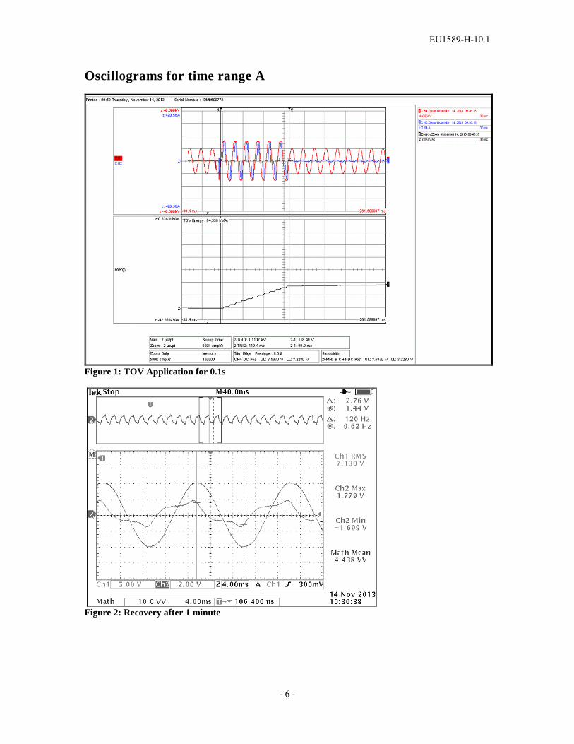
Oscillograms for time range A
Figure 1: TOV Application for 0.1s
Figure 2: Recovery after 1 minute

EU1589-H-10.1
- 7 -
Figure 3: Recovery after 30 minutes

EU1589-H-10.1
- 8 -
Oscillograms for time range C
Figure 4: TOV application for 1.2 s
Figure 5: Recovery after 1 min
EU1589-H-10.1
- 9 -
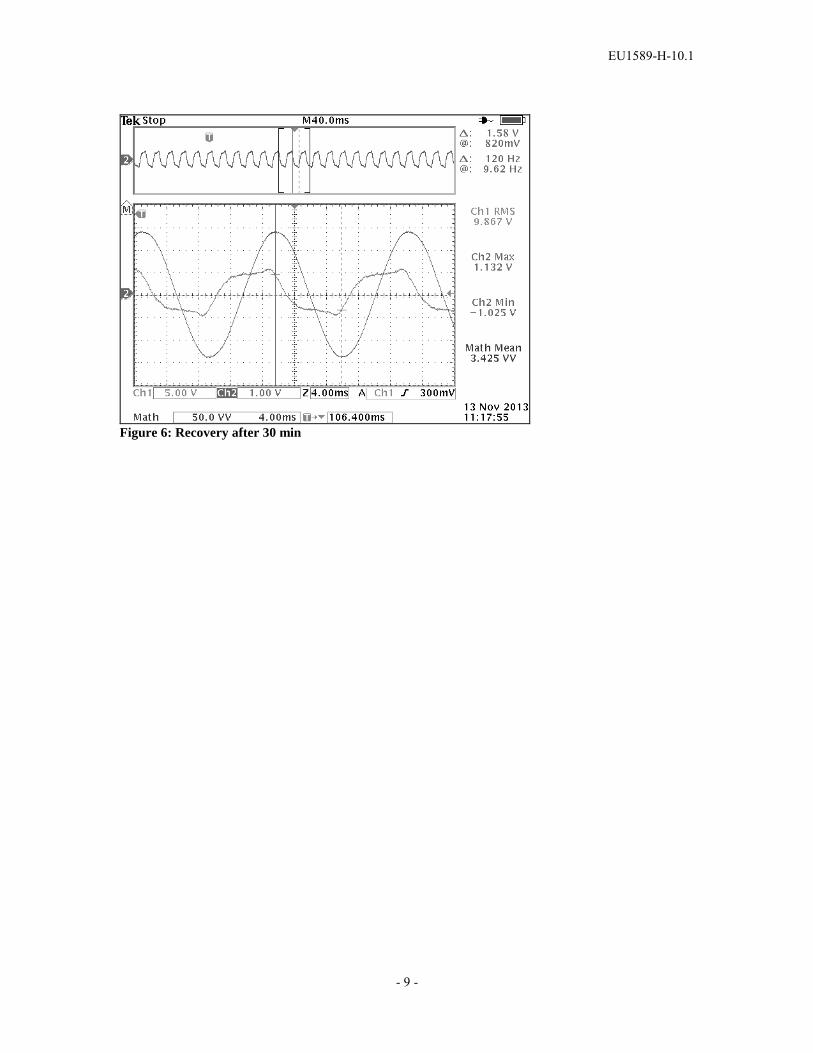
Figure 6: Recovery after 30 min
EU1589-H-10.1
- 10 -
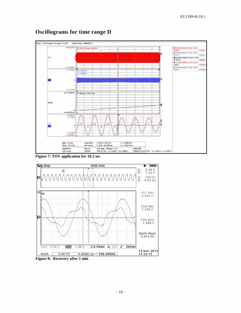
Oscillograms for time range D
Figure 7: TOV application for 10.2 sec
Figure 8: Recovery after 1 min
EU1589-H-10.1
- 11 -
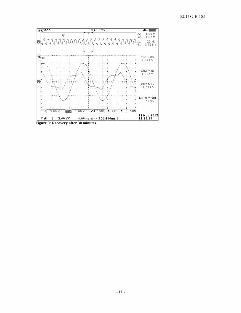
Figure 9: Recovery after 30 minutes

EU1589-H-10.1
- 12 -
Oscillograms for time range F
Figure 10: TOV at 1540 seconds
Figure 11: Recovery at 1 min

EU1589-H-10.1
- 13 -
Figure 12: Recovery at 30 min

Design Test Report Report No. EU1589-H-12.1
MVN Series Porcelain-housed Arrester
Short Circuit Test
This report records the results of type tests made on MVN series arresters, rated up to 444 kV (353 kV MCOV). Tests were performed in accordance with procedures of IEEE Std C62.11-2012, “IEEE Standard for Metal-Oxide Surge arresters for AC Power Circuits (>1 kV)”. To the best of our knowledge and within the usual limits of testing practice, tests performed on these arresters demonstrate compliance with the relevant clauses of the referenced standard. Michael Kelley Chris Kulig Senior Technology Manager Senior Design Engineer
Date: 11/15/13

EU1589-H-12.1
- 2 -
DESIGN TEST REPORT Short Circuit Test
TESTS PERFORMED: High current short circuit tests were performed at the CESI high power laboratory in Milan, Italy according to the procedures described in 8.18 of IEEE C62.11-2012 (identical to requirements of IEC 60099-4 Ed 2.2: 2009, Clause 8.7) to verify short circuit rated capability of 63 kArms symmetrical, according to Table 15 of IEEE C62.11-2012. The MVN series of arresters has a rated short circuit capability of 63,000 A symmetrical. Verification of capability requires three high current tests, performed with rated short circuit current (63000 A) and two reduced short circuit currents (25000 A and 12000 A) Three fully assembled test units were prepared, each containing as many non-linear resistor elements as possible within the available stacking length. The internal elements of each test unit were shorted by a fuse wire running along the outside of the stack of elements. The units tested had a length of 1308 mm (1451 mm with terminal cap), which represents the longest units used in the MVN series of arresters. RESULTS: Complete results of the testing are contained in a CESI test report that is available on request. Results are summarized in the following extracts from the CESI report. The test sample Figure 1 shows the general arrangement of the test set up. Figure 2 shows one of the units in the test chamber. Note: While the CESI test report indicates that the tests were performed on VH4 IEC Class 4 arresters, it should be noted that the samples tested are representative of the longest units used also in MVN arresters. The VH4 and MVN arresters use the same size of porcelain, same pressure relief system same size MOV blocks and same type of internal construction. The test samples therefore meet all the requirements of IEEE C62.11-2012. Furthermore, although the CESI tests were performed in 2004 (prior to the issuance of IEEE C62.11-2012), the procedures used in the tests were identical to the procedures now specified in IEEE C62.11-2012), and therefore the tests are sufficient to qualify the short circuit performance of MVN arresters according to the requirements of IEEE C62.11-2012. All three samples successfully withstood their respective short circuit current tests with no fracturing of the porcelain housing (in the case of the 12000 A and 63000 A tests, a small amount of breakage of weathersheds occurred, but the porcelain pieces did not fall outside the enclosure). Actual prospective rms values of test currents were 12600 A, 25500 A and 67000 A. For the rated current test, the peak of the first half cycle of test current was 169000 A, meeting the requirement that this be at least 2.5 times the rms value of the rated short circuit current. Data sheets for the tests are shown in Figures 3– 5, and associated oscillograms are shown in Figures 6 - 8. Figures 9 – 11 show the condition of the units after the tests.

EU1589-H-12.1
- 3 -
EVALUATION: The design meets the high-current pressure relief test requirements of IEEE C62.11-2012. The test sample successfully withstood the rated short circuit current test and the two reduced high current tests with no rupturing of the porcelain housing, and no release of internal components.
EU1589-H-12.1
- 4 -
Figure 1. Test circuit arrangement

EU1589-H-12.1
- 5 -
Figure 2. Test sample mounted in test chamber

EU1589-H-12
- 6 -
Figure 3. Data sheet for 12000 A test

EU1589-H-12
- 7 -
Figure 4. Data sheet for 25000 A test
EU1589-H-12
- 8 -
Figure 5. Data sheet for 63000 A test

EU1589-H-12
- 9 -
Figure 6. Oscillograms for 12000A test

EU1589-H-12
- 10 -
Figure 7. Oscillograms for 25000A test

- 11-
Design Test Report Report No. EU1589-H-12.1
MVN Series Porcelain-housed Arrester
Short Circuit Test
This report records the results of type tests made on MVN series arresters, rated up to 444 kV (353 kV MCOV). Tests were performed in accordance with procedures of IEEE Std C62.11-2012, “IEEE Standard for Metal-Oxide Surge arresters for AC Power Circuits (>1 kV)”. To the best of our knowledge and within the usual limits of testing practice, tests performed on these arresters demonstrate compliance with the relevant clauses of the referenced standard. Michael Kelley Chris Kulig Senior Technology Manager Senior Design Engineer
Date: 11/15/13

EU1589-H-12
- 12 -
Figure 9. Condition of sample after Oscillograms for 12000A test
Figure 10. Condition of sample after Oscillograms for 25000A test

EU1589-H-12
- 13 -
Figure 11. Condition of sample after Oscillograms for 65000A test

Design Test Report Report No. EU1589-H-11.1
MVN Series Porcelain-housed Arrester
Ultimate mechanical strength – static (UMS–static) test
This report records the results of type tests made on MVN series arresters, rated up to 444 kV (353 kV MCOV). Tests were performed in accordance with procedures of IEEE Std C62.11-2012, “IEEE Standard for Metal-Oxide Surge arresters for AC Power Circuits (>1 kV)”. To the best of our knowledge and within the usual limits of testing practice, tests performed on these arresters demonstrate compliance with the relevant clauses of the referenced standard. Michael Kelley Chris Kulig Senior Technology Manager Senior Design Engineer
Date: 11/15/13

EU1589-H-11.1
- 2 -
DESIGN TEST REPORT Ultimate mechanical strength – static (UMS–static) test
TESTS PERFORMED: A UMS-static test was performed on three of the longest mechanical units used in the MVN series of arresters. Tests were performed according to Clause 8.23 of IEEE C62.11-2012. For each sample, the unit was securely bolted to the floor of the testing machine and subjected to a cantilever load applied at the top end of the unit, perpendicularly to the axis of the unit. The loading was applied at a rate necessary to reach the desired bending moment in 30 s to 90. After reaching the target load, the load was maintained at not less than this level for at least 60 s. After release of load, the unit was inspected to verify that no mechanical damage had occurred. RESULTS: The MVN series of arresters uses one, two, three or four units (depending on voltage rating and overall creepage distance requirements), with all units using one general porcelain housing type (all housings have the same diameter and weathershed profile, differing only in height) and only one design of end fitting. The greatest bending stress is always at the bottom end of the bottom unit of the arrester, and according to the requirements of IEEE C62.11-2012, it is therefore necessary only to perform the test on the longest lower unit. The tested unit was the longest mechanical unit used in MVN arresters. The UMS-static rating of MVN arresters is 150,000 in-lbf (17 kNm), while the loading tests were performed at approximately 1.2 times this level. Loading curves for the three tests are shown in Figures 1 - 3. Examination of the units after the test revealed no damage to the units. EVALUATION: Each of the 3 units were tested to bending moments approximately 20% in excess of the UMS-static rating of 150,000 in-lbf (17 kNm) without damage, thereby exceeding the requirements of IEEE C62.11-2012.

EU1589-H-11.1
- 3 -
UNIT 1
0
5
10
15
20
25
0 50 100 150 200 250
Time - s
Ben
ding
Mom
ent -
kN
m
Figure 1. Loading curve to approximately 1.2 times UMS-static for Unit 1
UNIT 2
0
5
10
15
20
25
0 50 100 150 200 250
Time - s
Ben
ding
Mom
ent -
kN
m
Figure 2. Loading curve to approximately 1.2 times UMS-static for Unit 2

EU1589-H-11.1
- 4 -
UNIT 3
0
5
10
15
20
25
0 50 100 150 200 250
Time - s
Ben
ding
Mom
ent -
kN
m
Figure 3. Loading curve to approximately 1.2 times UMS-static for Unit 3