design thickness for flexible pavement
DESCRIPTION
For Highway EngineeringTRANSCRIPT

12/13/2015
1

12/13/2015
2
DESIGN EQUATIONS
where:
W18 = predicted number of 80 kN (18,000 lb.) ESALs
ZR = standard normal deviate
So = combined standard error of the traffic prediction and performance prediction
SN = Structural Number (an index that is indicative of the total pavement thickness required)
= a1D1 + a2D2m2 + a3D3m3
ai = ithlayer coefficient
Di = ithlayer thickness (inches)
mi = ith layer drainage coefficient
∆PSI = difference between the initial design serviceability index, P i, and the design terminal
serviceability index, Pt
MR = subgrade resilient modulus (in psi)
STANDARD NORMAL DEVIATES FOR VARIOUS LEVELS OF RELIABILITY
RELIABILITY (%) STANDARD NORMAL
DEVIATE (ZR)
RELIABILITY (%) STANDARD NORMAL
DEVIATE (ZR)
50 0.000 93 -1.476
60 -0.253 94 -1.555
70 -0.524 95 -1.645
75 -0.674 96 -1.751
80 -0.841 97 -1.881
85 -1.037 98 -2.054
90 -1.282 99 -2.327
91 -1.340 99.9 -3.090
92 -1.405 99.99 -3.750
12/13/2015
3
SAMPLE.Given R = 95%, SN = 5, S0 = 0.35, MR = 5000 psi (34.5
MPa), and ∆PSI = 1.9, determine W18 using the
design equation for flexible pavement.
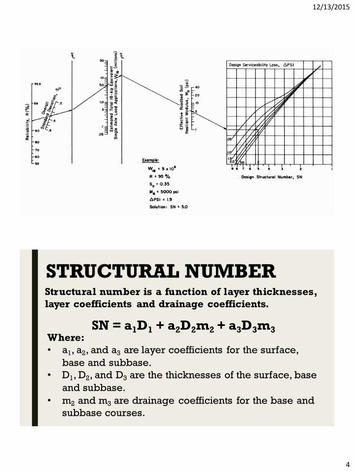
DESIGN CHART
Given W18 = 5 x 10⁶, R = 95%, S0 = 0.35, MR = 5000 psi (34.5
MPa), and ∆PSI = 1.9, determine SN using the design chart
for flexible pavements.
SAMPLE.
12/13/2015
4
STRUCTURAL NUMBERStructural number is a function of layer thicknesses,
layer coefficients and drainage coefficients.
SN = a1D1 + a2D2m2 + a3D3m3Where:
• a1, a2, and a3 are layer coefficients for the surface,
base and subbase.
• D1, D2, and D3 are the thicknesses of the surface, base
and subbase.
• m2 and m3 are drainage coefficients for the base and
subbase courses.

12/13/2015
5
SELECTION OF LAYER THICKNESSESOnce the design structural number SN for an initial
pavement structure is determined, it is necessary to select a set
of thicknesses so that the provided SN will be greater than the
required SN. Many combinations of layer thicknesses are
acceptable, so their cost effectiveness along with the
construction and maintenance constraints must be considered to
avoid the possibilityof producing an impractical design.
E1 a1
E2 a2 m2
E3 a3 m3
GENERAL PROCEDUREThe procedure for thickness design is usually
started from the top and described as follows:
1. Using E2 as MR, determine from design chart the
structural number SN1 required to protect the base, and
compute the thickness of layer 1 from
𝐃𝟏 ≥𝐒𝐍𝟏𝐚𝟏

12/13/2015
6
2. Using E3 as MR, determine from design chart the
structural number SN2 required to protect the subbase,
and compute the thickness of layer 2 from
𝐃𝟑 ≥𝐒𝐍𝟑 − 𝐚𝟏𝐃𝟏 − 𝐚𝟐𝐃𝟐𝐦𝟐
𝐚𝟑𝐦𝟑
3. Based on the roadbed soil resilient modulus MR,
determine from design chart the total structural number
SN3 required, and compute the thickness of layer 3 from
𝐃𝟐 ≥𝐒𝐍𝟐 − 𝐚𝟏𝐃𝟏
𝐚𝟐𝐦𝟐
SAMPLE.Figure 11.29 is a pavement system with the resilient
moduli, layer coefficients, and drainage coefficients as
shown. If predicted ESAL = 18.6 x 10⁶, R = 95%, S0 = 0.35,
and ∆PSI = 2.1, select thicknesses D1, D2, and D3.