design verification calculations stage crew 10m … corbett corbett engineering 16a ballylintagh rd...
TRANSCRIPT

Sam Corbett Corbett Engineering 16a Ballylintagh Rd Hillsborough Co Down BT26 6QG
Design Verification Calculations Stage Crew 10m Mobile Stage.
Stage Crew 10m Mobile Stage Registration no: Make: MAN Model: 18-224F (7.1m wheelbase) Maximum G.V.W (Kgs) 18,000 Vehicle weight prior to build: 5,350 Kgs

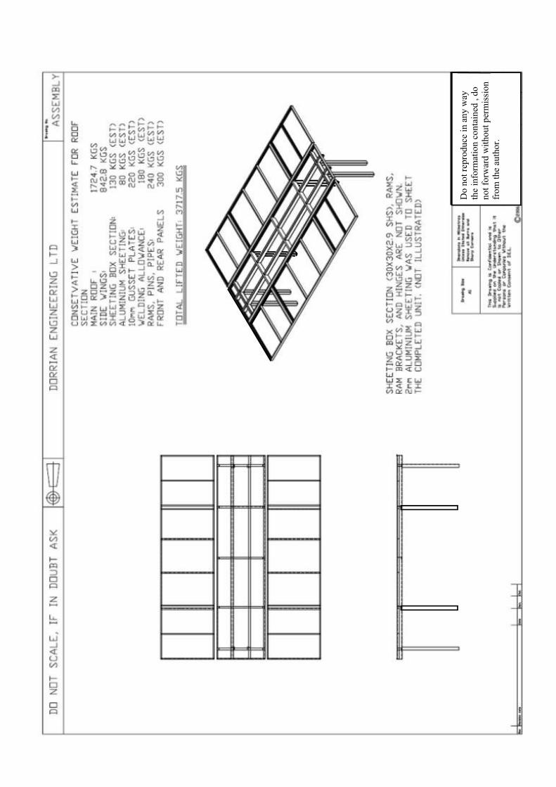
Vehicle Weight after build: 17,350 Kgs Therefore, body weight is 12,000 Kgs As seen below, the estimated weight of the roof section that raises up is 3,717.5 Kgs. (see pages 6,7,8,) With the roof weighing 3717.5 Kgs, it can be assumed that this loading will be split 50/50 between the front and rear uprights. Therefore 1,858.75 Kgs is loaded at a point 600mm (approx) in from either end of the chassis. The remaining weight of the body, that is to say 12,000 – 3,717.5 = 8,282.5 Kgs is uniformly distributed over the length of the truck. The gives us a UDF of 8282.5Kgs/9.115m = 908.67 Kg/m. For the purpose of analysis, the large truck chassis will be omitted from calculations and the body of the truck will be looked at independently. In addition, the two side chines of the truck will be omitted, and it will be assumed all loading is being carried by the chassis runners, which are 200 x 75 RSC. The point loads and UDL are halves, as there are two beams carrying the load. Therefore, the point loads are 930 Kgs, and the UDL is 454 Kg/m. The beam is simply supported in 3 positions by the hydraulic jacking system. The end jacks are approximately 500mm in from each end, with the third jack in the middle of the truck. The beam to be analysed is shown in figure 1. The resultant beam analysis results are shown in figure 2, with the beam properties used in the analysis shown on page 5.


------------------------------------------------------------------------------------------------------------------ BEAMBOY V2.2 REPORT ------------------------------------------------------------------------------------------------------------------ Stage Crew 10m Mobile Stage. ------------------------------------------------------------------------------------------------------------------ BEAM PROPERTIES ------------------------------- Beam Length = 9.15 m Moment of Inertia = 13600000 mm^4 Modulus of Elasticity = 205000 MPa Distance From Neutral Axis to Furthest Fiber = 102 mm LOAD CONFIGURATION ------------------------------------ Point Loads ------------------ 930 kg, x=0.6 m 930 kg, x=8.55 m Distributed Loads --------------------------- Start=454 kg/m, x=0 m; End=454 kg/m, x=9.15 m Moments --------------- Supports ---------------- Simple support; 0.5 m Simple support; 8.65 m Simple support; 4.58 m MAXIMUM VALUES ----------------------------- Maximum Bending Moment = -9410 N-m at x=4.58 m Maximum Bending Stress = 70.5 MPa at x=4.58 m Maximum Deflection = -2.49 mm at x=2.21 m Maximum Slope = -0.137 degrees at x=0.535 m 07/08/2006
From the results, the maximum deflection when it is assumed that there is no supporting truck chassis and no side chimes is only 2.49mm over a 9.15m bed. The maximum bending stress of 70.5 MPa (E:205,000 MPa) is well within the limits of the steel used. It can be said that with the additional support of the side chines and the chassis of the truck, The stage is comfortably fit for purpose.


The flip down side section of the stage has been manufactured as a heavy duty steel frame. The weakest link in this part are the hinge pins. A simple shear calculation will be compiled on the side panels to obtain the maximum permissible loading on these sections. When the panel is set-up for stage use, the inside edge is supported on 5 hinge pins, whilst the outer edge is a supported steel from with adjustable legs. For a worst case scenario, it will be assumed that two pins are missing, and the remaining pins have worn down to a diameter of 15mm. It will also be assumed that the pins are mild steel. Therefore Total area in shear is (ΠD2/4) * 3 where D is the diameter in meters (Π*0.0152/4) * 3 = 5.301 x 10⁻⁴ m2 The maximum load on the pins in double shear is given by Ơ x 2 x A = P, Where P = load in Kgs A= Area in shear in m2 Ơ = yield strength of mild steel in Kg/ m2 (36.9 x 10⁶ ) x 2 x (5.301 x 10-4 ) = 39,124 kgs The flip down section of the stage is safe to take any load up to 3.9 tonnes with a factor of safety of 10. The stage is fit for purpose. Roof Pins in Shear. A key to this design is that all parts of the stage operate hydraulically. Lock /burst valves are fitted to all rams, so that should the pipes fail, the pressure will be locked in the ram, which will keep the stage in position. In addition, all parts held up by rams are also mechanically supported. A key area in this design is the back-up pins in the main roof uprights. Should the seals in the rams or the pins in the rams fail, these pins will support the roof. Pin check Pin Diameter 40mm in mild steel. Again, it will be assumed that the pins have worn down to 35mm., and that there is only one pin in place at either end Total area in shear is (ΠD2/4) * 2 where D is the diameter in meters (Π*0.0452/4) * 2 = 31.8 x 10⁻⁴ m2 Pin in double shear Ơ x 2 x A = P,
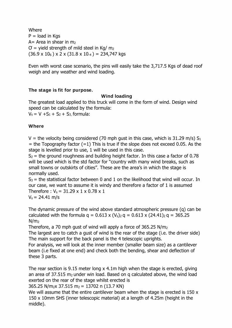
Where P = load in Kgs A= Area in shear in m2 Ơ = yield strength of mild steel in Kg/ m2 (36.9 x 10⁶ ) x 2 x (31.8 x 10-4 ) = 234,747 kgs Even with worst case scenario, the pins will easily take the 3,717.5 Kgs of dead roof weigh and any weather and wind loading. The stage is fit for purpose. Wind loading The greatest load applied to this truck will come in the form of wind. Design wind speed can be calculated by the formula: Vs = V +S1 + S2 + S3, formula: Where V = the velocity being considered (70 mph gust in this case, which is 31.29 m/s) S1 = the Topography factor (=1) This is true if the slope does not exceed 0.05. As the stage is levelled prior to use, 1 will be used in this case. S2 = the ground roughness and building height factor. In this case a factor of 0.78 will be used which is the std factor for “country with many wind breaks, such as small towns or outskirts of cities”. These are the area’s in which the stage is normally used. S3 = the statistical factor between 0 and 1 on the likelihood that wind will occur. In our case, we want to assume it is windy and therefore a factor of 1 is assumed Therefore : Vs = 31.29 x 1 x 0.78 x 1 Vs = 24.41 m/s The dynamic pressure of the wind above standard atmospheric pressure (q) can be calculated with the formula q = 0.613 x (Vs)2 q = 0.613 x (24.41)2 q = 365.25 N/m2 Therefore, a 70 mph gust of wind will apply a force of 365.25 N/m2 The largest are to catch a gust of wind is the rear of the stage (i.e. the driver side) The main support for the back panel is the 4 telescopic uprights. For analysis, we will look at the inner member (smaller beam size) as a cantilever beam (i.e fixed at one end) and check both the bending, shear and deflection of these 3 parts. The rear section is 9.15 meter long x 4.1m high when the stage is erected, giving an area of 37.515 m2 under win load. Based on q calculated above, the wind load exerted on the rear of the stage whilst erected is 365.25 N/m2x 37.515 m2 = 13702 n (13.7 KN) We will assume that the entire cantilever beam when the stage is erected is 150 x 150 x 10mm SHS (inner telescopic material) at a length of 4.25m (height in the middle).

A load of 13.7Kn/2 is being exerted ant both ends, and as there are 2 beam at each end the load on each beam is therefore 13.7KN/4 The beam being analysed is shown in figure 3 below


14

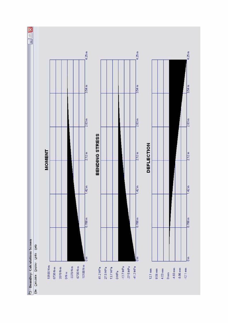
------------------------------------------------------------------------------------------------------------------ BEAMBOY V2.2 REPORT ------------------------------------------------------------------------------------------------------------------ Stage Crew 10m -Cantilever ------------------------------------------------------------------------------------------------------------------ BEAM PROPERTIES ------------------------------- Beam Length = 4.25 m Moment of Inertia = 18400000 mm^4 Modulus of Elasticity = 205000 MPa Distance From Neutral Axis to Furthest Fiber = 75 mm LOAD CONFIGURATION ------------------------------------ Point Loads ------------------ Distributed Loads --------------------------- Start=1120 N/m, x=0 m; End=1120 N/m, x=4.25 m Moments --------------- Supports ---------------- Cantilever support; 0 m, Reaction=4750 N, 10100 N-m MAXIMUM VALUES ----------------------------- Maximum Bending Moment = -10100 N-m at x=0 m Maximum Bending Stress = 41.2 MPa at x=0 m Maximum Deflection = -12.1 mm at x=4.25 m Maximum Slope = -0.217 degrees at x=4.25 m 08/08/2006 The analysis of the beam shows that the stress and the bending moment are acceptable, given that the bottom of the beam is gusted to relieve the bending moment. The maximum deflection is 12.1mm which is also acceptable, given that the beam is assumed to be free standing, where is actual fact it is tied to the other beam, and the actual maximum values will be lower than that theoretically calculated. It can also be said that before the beam will reach the values, the straps on the canvas cover will have ripped at the sides of the stage, preventing such a wind load being generated. However if we assume the simple beam analysis above, a worst case scenario (i.e. no tie to the second upright, no gusset plates, and the side canvas cover holds) then the truck is still fit for purpose The final calculation is to consider the uplift generated by the roof and the rear of the truck in a 70 Mph wind. From above we know that the rear panel exerts a force of 13702 N (13.7 KN) I addition to this force, the roof opened out could catch a full swirling up lift wind (worst case) Therefore, in addition to the 13.7 KN generated, the roof will generated an upward load of Roof: q x roof area

Roof: 365.25 N/m2 x (9.15 x 6.812) = 22,769 N (22.8KN) The total load by wind trying to lift (or overturn the truck) is 36.5 KN The total anchorage mass (weight of the stage and truck) is 17,250 Kgs (17,250 x 9.81N = 169.22 KN) The FOS is therefore 169.22/36.5 = 4.64,
The stage is therefore easily fit for purpose. For the purposes of safety, the stage should not be erected when wind speeds are reaching 50 mph.
These calculations have been compiled by: Sam Corbett Beng, Ceng MIMechE