design windows and economic aspect of helical...
TRANSCRIPT
Design Windows and Economic Aspectof Helical Reactor
Y. Kozaki, S. Imagawa, A. SagaraNational Institute for Fusion Science, Toki, Japan
Japan-US Workshop, Kashiwa, March 16-18,2009
Outline
- Background and Objectives
- HeliCos code - Basic equations and calculation flow
- The design windows boundary and β, γ dependence
- Estimating magnet cost based on ITER data
- Economical potential of heliotron reactors
- Conclusion

Background1) Many studies on system designs and economic evaluations of magnetic
fusion reactor had been carried out such as the Generomac by Sheffieldand the ARIES design studies. The most had concluded the smaller reactorwith high beta was necessary for attractive fusion reactors from the pointof view of mass-power density.→ But with high beta we should consider decreasing magnetic field, onthe other hand enlarging reactor size to ensure enough blanket space andto avoid too much heat flux for diverter.
2) As we have much experience of large size superconducting magnet fromLHD and ITER construction, we should estimate the magnet cost based onsome realistic database.
Objectives To search the design windows of heliotron reactors (LHD similar type
helical reactors) and to evaluate the economical potential.

System Design and Mass-Cost Estimating Code (HeliCos)- Major tasks and methodology-
System Design Code Standard Design Case Weight-Cost Analysis
4GW Standard PlantMagnet Cost Analysisbased on ITER
Cost Comparison toPrevious Works
(The next task with detail cost)
Mass-Cost EstimatingModel (HeliCos)
Design Windows AnalysisPlasma⇔ Magnet⇔Blanket
Mass-CostDatabase
Searching Design Windows ofHeliotron Reactor (γ, β dependence)
Estimating COE (cost of electricity)
Identifying CriticalParameters
FFHR-2m1 Design Study
FFHR-2m2 based on LHD 3.6m case
γ, β dependence
Δd limitationJ-Bmax condition
H factor in high βBlanket & T sys.
Conductor costwith j, Bmax

Guidelines for analysis on the Design Windows
1) Logical results →from basic equations with the clear preconditions
2) Self consistent →with comprehensive view of plasma, magnets and reactor
3) Reasonable and affordable →Don’t design on the cliff →To open the design windows wide
→ Searching design windows logically with clear conditions

HeliCos code - Major design parameters and relationships (1) 1) Basic geometry of plasma and helical coils given with Rp, γ, and Δd
→ The fat plasma increases plasma volume but decreases blanket space.→ It depends on γ.
→ We can consider the similar shape of the LHD 3.6m inward shift cases for the highperformance of plasma with variable γ (LHD → polarity l=2, field periods m=10, coil pitch
parameter γ =(l/m)/(Rc/ac) is corresponding aspect ratio, γ=1.15~1.25 variable in LHD experiment)
→The ap and apin are given by the equations of regression of LHD data. (ap , ac : minor radius of plasma and coill, apin : inner minimum plasma radius)
FIG.1 The profile of plasma, helical coiland blanket. The required Δd gives theminimum Rp
ap=ac ( -1.3577+1.603 × γ ) =0.06292× γ4.5 Rp → τE
apin=( -1.2479 + 1.2524 γ ) ×( Rc /3.9)
→Blanket space
Δd = ac - (Rc-Rp) - apin - H/2 - Δt --------(1)
Δt : thermal insulation space (Δt =0.1 m)
H : The coil thickness depending on the IHC and j
(IHC , j :current and current density of helical coils )
→ IHC=( RP / B0)/(2m) ×10
H=( IHC / ( j × W/H))0.5 (W: width of HC)

Major design parameters and their relationships (2)2) Fusion power given with B0, β, and VP The fusion power is calculated by the volume integration of fusion power density pf using the following <σv>DT and the plasma profile assumptions in the HeliCos code. pf = nT nD <σv>DT Vp×17.58(MeV) ×1.6021×10⁻¹⁹ (J/eV) ×10-3 [GW] <σv>DT=0.97397×10⁻²²×exp{0.038245 (ln(Ti))3 - 1.0074 (ln(Ti))2 + 6.3997 ln(Ti) - 9.75}(m3/s)
→ parabolic profile index an : plasma density, aT : ion temperature→ a good approximation <σv>DT ∝ Ti
2 for Ti-~10keV using for sensitivity studies.
Pf =0.06272/(1+2an+2aT) ×ne(0)2Ti(0)2 VP ×10-6 ∝β2 B04 VP [GW] ne:1019/m3, Ti :keV (2)
3) Power balance conditions given with scaling low ISS04 in H factor equationsThe power balance is described using the required energy confinement time τΕr,
Pα - Rloss=Wp / τEr ( Pα =0.2Pf, fα :α heating efficiency, Rloss:Radiation loss Wp : plasma stored energy, Wp∝ne(0)Ti(0)Vp )
→ τE(ISS04)=0.134 (fα Pα- Rloss) -0.61 nel0.54 B0
0.84 RP0.64 ap
2.28 ι2/3 0.41
=6.23×10⁻⁵ Rp1.09 γ2.98 (pf(1- rloss))-0.61 B0
0.84 nel0.54 [ms]
(Expressed only with the Rp γ , B0, pf = Pf / Vp , rloss= Rloss /(0.2 fα Pf), rloss: radiation loss rate)
Hf (ISS04)= τEr / τE(ISS04)=76.4 × fnp× Rp -1.09 γ -2.98 pf
-0.16B0 -1.11 (1 - rloss)
-0.66 (3)

Design points given with the cross points of the three basic equations
1)The function B0(Rp , γ, Δd, j) from the Δd-equation (1) B0=(16j/Rp)((0.2633- 0.1312 γ) Rp - 20.41(Δd +0.1)) 2 [T] (4)2) The function B0(Rp , γ, β, Pf) from the Pf -equation (2) B0=92.64 Pf 1/4 β -1/2 γ -2.22 Rp
-3/4 [T] (5)3) The function B0(Rp , γ, Hf, Pf) from the Hf -equation Hf =76.4 × fnp × Rp
-1.09 γ -2.98 pf -0.16(1 - rloss)
-0.66 B0 -1.11 (3)
FIG.2 Design points given by thecross points of the three basicequations
(4)Δd=1.1m
(5)β=5%
(3)Hf=1.09
We can calculate the major design parameters,B0, Rp, γ, Pf , based on the three equations (1),(2),(3).
→ The cross points of the three equations on the B0-Rp plane.
Figure 2 shows a cross point of those three equations, withthe common assumptions of γ=1.2, Pf=4GW, an=0.5, aT=1,j=26 A/mm2 , and with the constant key parameters in each equation, Hf=1.09 in (3), β=5% in(5) and Δd=1.1m in(4).

Major design parameters and calculation flows
ap=f0(Rp, γ) Δd=f1(Rp, γ, B0, j) Eq.1
Pf=f2(β, B0,Rp, γ)
Diverter,Power flow,Mass flow
Hf=τEr/τEISS04=f3 (Rp, γ, B0 , Pf , ne) Eq.3)
Identifying CriticalParameters
β, Pf
<Density limit, Profile>
LCFSErgodic layers
Optimizing the coilconfigurations andthe current.
【Plasma size, shape】 【Pf, power balance, B0】 【Reacto system】
Vp=f0(Rp, γ)
<ap><apin><iota> T breading ratio
Ergodic layer
τEr=Wp/ (0.2fαPf-Ploss)
B0 =f2’(Rp, γ) Eq. 2
Eq. of regressionfrom LHD data

Fig.2-3 The B0-Rp relationships depending on γ and Δd [The minimum Rp line is givenby the cross points of the Pf=4GW lines and Δd=1.1m lines for each γ.]
The minimum Rp is given with Δd constraints for each γ -How to get design points of 4GW-β 5% plants with Δd1.1m-

Fig.4 The design windows limited with Δd≥1.1m, Hf≤1.16, W<160G, depending on γ (β 5%, Pf 4GW).Hf=1.16 means the enhancement factor of 1.2 to LHD experiment [1]. j=26A/mm2 precondition.
Design windows limited by the constraints of Δd and H factor
1) Δd constraints give the lower boundary of Rp (increasing γ, ap →enlarging Rp)2) H factor constraints give the lower boundary of B0 (larger Rp , γ→decreasing B0)3) The constraints of magnetic stored energy W give the upper bounds of B0→ Serching with the constraints of Δd≥1.1m, Hf≤1.16, W<160G
γ=1.15
γ=1.20
γ=1.25
Δd=1.1mΔd=1.15
Δd=1.2m
Δd=1.05m
γ=1.15γ=1.20
γ=1.25
HF≦1.16Δd ≧1.1m
β5%, Pf 4GW case B0 W

The heliotron reactor design windows depending on γ and β The design windows on Rp-B0 plane limited with Hf<1.15 and W<160 GJ (Δd=1.1m).
The low β(~3%) conditions severely limit the fusion power less than Pf=2GW.In the high β(~5%) conditions the large fusion power (~4GW) plants are not limited by W, but H factor constraints restrict the small fusion power plants.
Fig. 5-1 The design windows of 2~4GW fusion power plants limited with theconstraints of Δd=1.1m, Hf≤1.15, W<160GJ. The γ dependence are shown with thefour points, γ=1.15, 1.18, 1.20, 1.25 on each line.
Hf=1.15
2GW3GW
4GW B0 β 3%
γ=1.25
γ=1.15γ=1.18
γ=1.20W=160GJ
Hf=1.15
2GW
3GW
4GW
W=160GJ
B0 β 4%
W=160GJ
Hf=1.152GW
3GW4GW
B0 β 5%

The heliotron reactor design windows strongly depending on β The design windows clearly shown on Rp-W plane limited with Hf<1.15 and W<160 GJ)
β3% → only Pf=2GW in W~160GJβ4% → B0=4.5~6T→Pf=3~4GW, although W =140~150GJβ5% → We can consider the optimum design windows of Pf=3.3~4GW plants with RP=14.6~16.3m, B0=4.4~5.5T, and W=125~140GJ
Fig. 5-2 The design windows of 2~4GW fusion power plants limited with theconstraints of Δd=1.1m, Hf≤1.15, W<160GJ. The γ dependence are shown with thefour points, γ=1.15, 1.18, 1.20, 1.25 on each line.
W β 5%
4GW
3GW
2GWHf<1.15
W β 3%
W<160GJ
Hf<1.15
2GW
3GW
4GW
Hf<1.152GW
3GW
4GW
W β 4%

Design Parameters Symbol (unit) 4GW standard plants =5%, Hf=1.06-1.15
3GW Hf=1.15
Coil pitch parameter 1.15 1.20 1.25 1.20 Coil major Radius Rc (m) 15.91 16.70 17.63 16.69 Plasma major radius Rp (m) 14.69 15.42 16.27 15.40 Plasma radius ap (m) 1.78 2.27 2.85 2.27 Inner plasma radius apin (m) 0.78 1.09 1.44 1.09 Plasma volume Vp (m3) 916 1565 2604 1561 Magnetic fie l d B0 (T) 5.74 5.02 4.42 5.00 Average beta 5.0 5.0 5.0 4.37 Fusion power Pf (GW) 4.00 4.00 4.00 3.00 H factor to ISS04 H f 1.064 1.094 1.151 1.150 Maximum field on coi l s Bmax ( T ) 12.16 11.91 11.78 11.88 Coil current IHC (MA) 42.18 38.67 35.93 38.50 Coil current densit y j (A/mm2) 26.0 26.0 26.0 26.0 Helical Coil hei g h t H (m) 0.90 0.86 0.83 0.86 Blanket spac e d (m) 1.10 1.10 1.10 1.10 Neutron wall loa d s fn (MW/m2) 2.9 2.2 1.7 1.7 Magnetic stored ene r g y W (GJ) 144 131 123 130
Table 1 The Standard helical reactors of 3~4 GW Fusion Power(1)
*Effective ion charge Zeff=1.32, **Alpha heating efficiency 0.9, and parabola profile index an=0.5,aT=1.0.

Guidelines for Cost Analysis
1) Objective cost estimation →mass-cost analysis based on the consistent design
2) Comparable cost with other power plants →with the same economic calculation method and the
common cost data basis
→ Cost estimation based on the design windows and theunit cost reflected the progress of recent fusiontechnology

Table 1. Analysis on Weight and Cost of Magnet Systems based on ITER (1kIUA=144Yen)
The weights of coil system elements are calculated based on the technical design data. Costvalues in italic are calculated by using the cost data those of the ITER Report, the FDR costsand the unit cost data by Mitchell 1999.
ITER Report 2002 ITER FDR 1999TOKAMAKCoil
Systems
Elements Weight
ton
Unit Cost
Myen/ton
Cost
MYen
Weight
ton
Unit Cost
Myen/ton
Cost
MYen
Conductor Strands 483 63.3 30,564 1280 54.0 69,099
Conduit 137 2.9 396 380 8.1 3,064! ! 620 50.0 30,960 1660 43.5 72,163
Radial Plate 1212 6.5 7,854 2900 8.1 23,579
Winding ( Weight) (1832) 8.9 16,266 (4560) 11.3 51,434
C1.TF coilNb3Sn/Cu(Cu ratio:1)
Coil Case ! 4289 3.3 14,184 9000 3.3 29,539
! ! ! 6120 10.0 59,335 13560 13.0 176,715
Conductor Strands 149 62.9 9,387 273 52.5 14,323
Conduit 441 8.1 3,573 457 8.1 3,685! ! 590 22.0 12,960 730 24.7 18,008
Radial Plate 0 ! ! 0 ! 0
Winding ( Weight) (590) 8.3 4,879 (730) 14.2 10,365
C2. CS CoilNb3SnCu
Cu ratio:1
Coil Case ! 250 3.3 824 400 4.6 1,852
! ! ! 840 22.2 18,662 1130 26.7 30,225
Conductor Strands 278 28.9 8,041 814 25.1 20,398
Conduit 902 2.9 2,615 3174 2.9 9,141
! ! 1180 9.0 10,656 3988 7.4 29,539
Radial Plate 0 ! ! 0 ! !
Winding ( Weight) (1180) 3.6 4,298 3988 3.8 15,288
C3. PF coil
NbTi/CuCu ratio: 1
Coil Case & Support 862 2.9 !2,499 0 ! !
! 2042 8.5 17,453 3988 11.2 44,827
C4. Coil Supports ! 1164 2.9 3,377 3200 5.6 18,008
C5. Other Systems (Feeders etc.) ! ! 6,739 ! ! 5,571
Total Weight & Direct Cost 10166 10.6 107,641 21878 12.6 275,346

Table 2. Estimation on Weight and Cost of Helical Reactor Magnet Systems basedon FFHR-m1 Design Study and ITER Magnet Cost
Coil
Systems Elements !! Weight ton
Unit Cost
Myen/ton
Cost
MYen
Conductor Strands 960 ! 63.3 60,723
! Conduit 2,077 ! 2.9 6,023
! ! 3,037 ! 22.0 66,747
Winding ! 3,037 10.7* 32,431
Coil Case ! 1,770 ! 3.3 5,809
C1.
Helical Co i l !
Nb3Al/Cu
(Cu ratio: 1)
! ! ! 4,807 21.8 104,987
Conductor Strands 1,001 ! 28.9 28,929
! Conduit 2,092 ! 2.9 6,067
! ! 3,093 ! 11.3 34,995
Radial Plate 1,717 ! 6.5 11,163
C2. Poloidal
(OV&
IV)Coil
NbTi/Cu
(Cu ratio: 3) Winding ! 4,810 4.4* 21,165
Coil case ! 0 ! ! !
! ! ! ! 4,810 14.0 67,324
C3. OV& IV Coil Support ! ! 6,085 3.3 20,081
C4. Other Coil systems 0.1*Sum(C1:C 3 ) ! ! ! 19,239
Total Weight & Direct Cost ! 15,702 13.5 211,631
*We consider winding unit cost of Helical Coil is 1.2 times that of Tokamak Coil, and
Poloidal Coil is 1/2 as same.

Concept of Winding Helical Coil
<Shear strain by winding>
!
r" =r # tan$1%
2&ac
4
~ 0.3%
(1) Conductors are heated for reaction of Nb3Al on a bobbin the circumference ofwhich is same as the length of one pitch of the helical coil.
(2) The conductors are transferred to the reel of the winding machine.(3) The conductors are pulled aside by the winding guide and wound in grooves of
the inner plate with being wrapped with glass tapes.(4) After winding the whole turns
in a layer, the next innerplate are assembled.
The effect of the torsionstrain on SC propertiesis not known.Further feasibility studyis needed.

Magnets Weight and Cost of Tokamak and Helical Reactor
Weight ton
FFHR 2m1-1.2 GWe
Cost B Yen
FFHR 2m1-1.2 GWe
ITER 2006 ITER 2006
ITER FDR 1998 ITER FDR 1998
Helical Reactor Tokamak Reactor * estimated with the first version
ITER SSTR*Magnetic stored energy 135 GJ 2.5 times(ITER) 50 GJ 140 GJ Weight 15.7 k ton ~ 1.6 times 10 k ton 11.2 k ton Cost 210 B yen ~ 2 times 110 B yen 140 B yen

Cost estimating methods and the major assumption
-The COE (Cost of Electricity) is calculated with the general cost estimatingmethod, the unit cost data and the scaling lows for BOP (balance of plant). Thecost of magnets and blanket -shield are the most important for economicalfusion power plants, then we estimated them based on mass-cost analysis.
- Key assumptions on FCR (Fixed charge rate)= 5.78%, with 40 years plant lifetime and 3% discount rate (Using in Japanese AEC cost estimation for LWRchanged from FCR=9.5~11% in the past COE estimation)
-The O&M cost (operation and maintenance cost) ; The ratio of O&M cost toconstruction cost is assumed 4.5 % for the conventional components, but 1.5%for magnets considering the inherent characteristics of super conductingmagnets.
-Availability factor is calculate as a function of neutron wall load.→ small size → small initial weight of blnaket but frequent replacement → decreasing plant availability that is very sensitive to required time for replacement

Design Parameters Symbol (unit) 4GW standard plants =5%, Hf=1.06-1.15
3GW Hf=1.15
Coil pitch parameter 1.15 1.20 1.25 1.20 Fusion power Pf (GW) 4.00 4.00 4.00 3.00 Weight of Blanket and shie l d Mbs (ton) 8580 11360 14920 11340 Magnetic stored ene r g y W (GJ) 144 131 123 130 Weight of magnet s Mmag (t o n ) 18000 16400 15400 16200 Magnet cost (%)*** Cmag(M$) 2079(34.6) 1893(31.0) 1780(28.0) 1875(33.7) Blanket and shield cost (%)*** Cbs (M$) 889(14.8) 1177(19.3) 1546(24.3) 1175(21.1) Total construction cost C total (M $ ) 7270 7393 7705 6735 Net electric power Pn (GW) 1604 1601 1598 1194 Total auxiliary power Pa (GW) 109 112 115 91 Plant availability fac t o r fA 0.680 0.706 0.726 0.727 Capital cost mill/kW h 44.0 43.2 43.8 51.2 Operation cost mill/kW h 26.8 27.1 28.2 31.4 Replacement cost mill/kW h 8.18 8.19 8.21 8.24 Fuel cost mill/kW h 0.023 0.022 0.021 0.021 COE(Cost of electricity) mill/kWh 79.0 78.5 80.3 90.9
Table 2 The Cost Comparison of Helical Power Plants (Fusion Power 3~4 GW)
# The major assumption for calculating COE are FCR (Fixed charge rate); 5.78%, with 40 yearsplant life time and 3% discount rate, the ratio of operation and maintenance cost to constructioncost; 4.5 % for the conventional components, but 1.5% for magnets considering the inherentcharacteristics of super conducting magnets.## Availability factor is calculate as a function of neutron wall load.

The magnet cost, blanket-shield cost, and the COE1) With increasing Rp and γ, the blanket-shield cost increases but the magnet cost decreases, as B0 decreases much with increasing γ (~Vp)2) The COE decreases strongly with increasing β from 3% to 5%.3) We should select the size (Rp, γ ) and B0 with considering the trade-off between magnet
cost and blanket cost, and also plant availability.
Fig. 2 . The B0, magnet cost (Cmag), and blanketCost (Cbs) depend on Rp, γ and β. When Rp and γincrease, Cmag decreases but Cbs increases.Those plots on Rp (γ) are given with Δd=1.1m.
The COEs of helical reactors, which dependon Rp, γ and β, show the bottom as the resultof the trade-off between the Cmag and Cbs,i.e., B0 versus plasma volume.
γ 1.15
γ 1.18
γ 1.25γ 1.20

Fig6-1The design windows changed with current density(j=26~ 30 A/mm2, β5%, Pf4GW)
Sensitivity studies on current density (j=26~ 30 A/mm2)
→increasing j ( 26A/mm2 →30A/mm2 ) →decreasing the coil thickness → increasingΔd or decreasing Rp and W
j= 26A/mm2
Δd=1.1-1.2 mj= 30A/mm2
Δd=1.1-1.2 m

The magnetic stored energy W and COE are reduced effectively bythe higher current density (shown in the dependence on γ).
COE depending on j,γ(Pf4GW, β5%)
Magnetic stored energy W andthe minimum major radius Rp
The magnetic stored energy W, the minimum major radius Rp, and COE decrease in thehigher current density, depeding on γ. ( j=26, 30, 34 A/mm2, Δd=1.1m constraints)

Conclusions
1) LHD-type helical reactors have the attractive design windows in rather large size ofRp = 15~16m, with the sufficient blanket space and the reasonable magnetic storedenergy of 120~140 GJ based on the physics basis of Hf ~1.1 and β~5%.
2) The β dependence is very sensitive for selecting the optimum fusion power withreasonable magnetic stored energy, so that the near β ~5% plasma with goodconfinement is the most important issues for economical fusion power plants.
3) The γ dependence is essential in Heliotron reactors that is critically sensitive notonly for optimizing LCFS (plasma volume) but for selecting the optimum blanketdesign.
4) There are many remaining subject to be studied, in especially the problem of theparticle and heat loads on the diverter is a critical issue to be considered in the nextanalysis, but heliotron reactors have high potential for economically attractive powerplants because of the inherent features of steady state operation and the flexibility ofselecting reactor size.
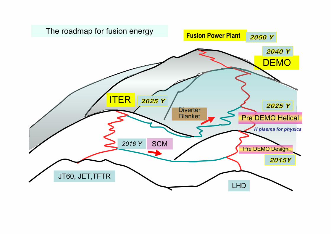
H plasma for physics
JT60, JET,TFTRLHD
SCM
Fusion Power Plant
DEMO
DiverterBlanket
ITER
Pre DEMO Helical
The roadmap for fusion energy
Pre DEMO Design2016 Y