designing a collector overlay architecture for fault diagnosis
TRANSCRIPT


designed with a networking element between the encoding anddecoding processes. The process of delivering streaming contenttypically involves elements such as video-grooming, encoding,network transmission, decoding and playout. Since errors canpotentially occur at each of these elements, there is a need tocontinuously monitor quality degradation. Quality evaluation strat-egies of the future shall require architectural support to performeffectively.
We propose a hierarchical overlay of decentralized collectornodes. A collector node is a sensor probe that captures and dissem-inates various statistics about a network, like number of droppedframes, network delay, jitter etc. on a given segment of a network.Note that most of present day access networks already have thenecessary infrastructure to deploy this: compiling usage statisticsfor billing purposes requires snooping into the user traf“c to gatherstatistics. We simply extend and leverage this basic infrastructureto form a hierarchical organization of such collectors with sensingelements at the leaf and a correlating platform at the root form acollector network overlay, or simply, collector overlay.
A collector overlay in converged multi-service networks playsan important role in fault diagnosis, capacity planning, dynami-cally assessing network optimization needs, and monitoring ser-vice usage. Collector overlays are hidden (i.e., they do not havepublished IP addresses) and unobtrusively gather service speci“cinformation at distributed sensing points, and then propagatethem to the ANCON (ANalysis and CONtrol) root node. Based onsensitivity of observed phenomena, ANCON generates actionevents that are routed to appropriate provisioning elements ofthe network. The collector overlay thus becomes the distributedvirtual sensor for the physical network that deploys services. Sucha network implicitly solves three important problems: (i) it canlocally identify impairment points; (ii) ANCON can provide realtime feedback to source about the current network status; and,(iii) it enables a continues quality scoring mechanism if suchcollectors can estimate video quality. Speci“cally, we make thefollowing contributions:
� We present an architecture of a hierarchical collector overlaythat gathers and disseminates network statistics. The nodesare decentralized and monitor local segments, and can controldistribution of this information. We justify such an architecturewith extensive experiments.� Using our overlay, we reverse engineer causes of network
induced degradation. Collector networks can isolate both thecauseof degradation and identify impairment segments/subnetsthat caused the degradation. This helps service providers reactto outages quickly and maintain high user satisfaction levels.� Our architecture provisions a feedback mechanism where the
source/local-segments can be informed of network statistics inreal time. This would allow network aware streaming applica-tions to better adapt to changing network conditions. This formof feedback is not possible with the conventional UDP/IP stack,which is inherently lightweight and best effort in nature.� We create an instrumentation layer above the data plane that
computes local MOS, and correlates to compute global MOS.We export to service providers an estimate of local MOSin a seg-ment rather than a series of network statistics to monitor healthof a segment. This, along with various other tunable parameters,allows for ef“cient root causes analysis where fault detectioncan be performed if the health of a segment goes down. Ourarchitecture seamlessly encompasses a wide variety of qualityscoring mechanisms, under a simplifying assumption that thescoring mechanism works on quantitative inputs that manifestas a unique quality score.
� Our MOS calculations at the ANCON node could predict thequality of video at destination much before playout. We com-pare these MOS predictions to PSNR and observe that the resultscorroborate with each other.
Though the main goal is to discover faulty behavior and predictthe service quality of video ”ows, the architecture can be easily ex-tended to perform other video and network performance relatedservices. Some of these are performance discovery (e.g., measuringround trip times of TCP/UDP), topology discovery (e.g., part or fullconnectivity), service usage discovery (e.g., who is using what ser-vice), fraud discovery (e.g., illegal usage), and trend discovery (e.g.,forecasting user demands and preferences).
The rest of the paper is organized as follows. Related work ispresented in Section 2. In Section 3, we argue the need for collectoroverlay and discuss its relevant characteristic features. Our simula-tion testbed is described in Section 4. In Section 5, we reverse engi-neer playout degradation to its causes in the network, and isolateimpairment points. In Section 6, we present a simple video-MOSmodel that considers delay and loss rate. We present a schema ofcalculating video-MOS continuously along the data path using col-lector nodes in Section 7. Conclusions are drawn in the last section.
2. Related research
Signi“cant work has been done in the areas of overlay networks,video quality measurement and network level measurements.However, to the best of our knowledge, we are not aware of anoverlay network architecture within an access network that candetect, isolate, diagnose impairments, and also allow implementa-tions of video quality measurements. An overlay architecture ismostly applied at the application layer, and its deployment gener-ally does not warrant changes to the underlying networking sub-strate. The concept of overlays is not new to networking: in fact,the Internet itself was designed as an overlay over the telephonenetwork.
Overlays have enjoyed popularity in related networking do-mains. Resilient overlay network (RON) [2] improves robustnessand availability of Internet paths between hosts. It can discoveroutages and suggest workarounds: it allows a small group of dis-tributed applications to detect and recover from outages in seconds(compared to several minutes of recovery in the Internet). Thoughour work in similar in philosophy (discovering outages), RON ismore applicable to general traf“c over the Internet. Network awareapplications can make use of the CMU Remos [10] , which providesa wide range of information to the application in a network inde-pendent fashion. Like our architecture, Remos gathers and controlsdistribution of information about individual subnets. However, thedesign emphasis on Remos has to been to provide a uni“ed infor-mation interface to applications which operate over a diverse net-working substrate, like the Internet. Apart from video applications,there has been some interest in designing overlay architectures toenable packet loss recovery and rapid rerouting of VoIP packets [1]over the Internet. Once again, our area of focus and design philos-ophies are completely different.
Extensive research has been performed by various groups to-wards objectively assessing quality of a video stream. Even at atime when there is little or no consensus on the exact nature ofsuch a model, the basic idea has been to provide a subjectivelyinterpret various events on a video stream, such as loss, delay, jitterand so on. For example, authors in [11] train a random neural net-work to adjust to viewer responses, and infer the quality of a videostream based on what is observed along the data path. Typical
M. Venkataraman et al. / Computer Communications 35 (2012) 418…430 419
efforts usually culminate in a mean opinion score (MOS), which ona chosen scale rates the quality of a particular sequence. MOS as ametric has been known to have its share of drawbacks [7,19] : (i)subjects tend to avoid the extreme scores, (ii) ••forgiveness effect••,where users tend to give higher rating when a playout is long andsmooth, is not uncommon; and (iii) quality in itself is not a verywell de“ned notion, and has many dimensions to it.
As an alternate to asking users to provide a MOS score, certainother techniques have also been employed. Some studies, instead,ask the user to provide certain speci“c feedbacks. For example,users could be asked to report visibility of certain artifacts onscreen [12,13] , or to suggest changes to artifacts to make the se-quence more appealing to them [4,15] . As can be seen, there isno one consensus on an acceptable quality assessment at the timeof this writing. Thus, and to make our architecture ”exible to manytypes of scoring schemes, we make a simplifying assumption: qual-ity assessment shall operate on the basis of certain well de“ned in-puts that can be drawn from the data plane. Note that thisassumption is oversimplifying, since it assumes no reference framein place for a direct comparison. These inputs could report certainspeci“c events that happen on the data place, like a frame loss, thetype of frame that was lost, delay, jitter and so on. As an example ofinstrumenting a quality evaluation based, we devise a rudimentaryMOS that can be calculated from such inputs. Since our goal is notto propose a new standard for MOS, we instead show that we caninfer the health of a network segment (instead of the video stream)to successfully identify impairments. This also implies that otherquality assessment techniques, once standardized or found suit-able, can easily replace our model of MOS, which only reportsthe health of a network segment.
There have also been various proposals for protocols and tech-niques that mitigate network induced errors. Zhu et al. [21] presentan algorithm that allows for simultaneous design of source ratecontrol and QoS-aware congestion control for streaming video.They utilize a virtual network buffer management, which allowsto capture application speci“c QoS requirements which can beinterpreted in terms of the source rate and the sending rate. Huanget al. [6] propose JitterPath, which is a noise resilient availablebandwidth estimation scheme. There has also been considerablework on packet loss resilience: Yang et al. [20] exploit the fact thatnot all packets or frames are of equal importance in a video streamand design a recovery scheme based on FEC. We acknowledge thevast breadth of recovery schemes possible from prior research. Weargue that, with the overlay and a feedback mechanism in place,one can use any of the available scheme or devise newer ones thatcan avoid or react to network related outages.
3. Collector overlay
VoD and IPTV services are usually centered around an accessnetwork. An access network has a video source, and terminatesat an edge-QAM (or E-QAM). Access networks are usually managedby service providers, and are typically run over IP. This section de-tails the instrumentation of a collector overlay in such accessnetworks.
3.1. Topology overview
A video network along with the possible collector overlay isshown in Fig. 1. Acquired video (either by satellites or alternativesources) is pushed by the VoD or the SDV pump. Video packetspass through a ••Groomer•• where variable bit-rate traf“c is policedto an almost constant bit-rate traf“c. Video data then passesthrough a series of routers (in the IP domain) before it reaches••M-join•• (multicast join node). The routers ( NE0 and NE1) poten-
tially multiplex various other traf“c within the access network.At Mjoin, selected ”ows are pulled on-demand (via control planeinfrastructure not shown) through the Edge-Qam (EQAM). The ac-cess network terminates at E-QAM, and what follows next is a ser-ies of ••passive•• nodes. Bandwidth allocation for all video ”ows aredone at the E-QAM and streams distributed over “ber nodes. Thevideo signal is ampli“ed before reaching the set-top box (STB)and the corresponding television (TV).
We begin with an overview of the overlay architecture. Thetopology can be loosely classi“ed in two broad categories: (i)exporters, or elements that have information to stream, and (ii)collectors, elements that gather incoming parameters, and poten-tially pass them to higher nodes. Exporters snoop into user traf“cthat they forward, and stream ”ow statistics to collectors. Usageof the collector overlay calls for some judiciousness in monitoring.If too many parameters are monitored per ”ow, the traf“c volumeof the collectors will begin to show exponential growth. This prob-lem is attributed to two clauses: (i) the number of parameters per”ow, which is to identify the most pertinent information desired;and (ii) the rate (i.e. frequency) of information streaming, whichin our architecture is a tunable parameter exported to serviceproviders.
Extensive simulations have been conducted (see, for e.g. [18] ) totest the sensitivity of subjective video quality perceptions in theface of various networking events. Of the metrics tested, namelydelay, loss, jitter and error, it is well accepted that loss is the mostdamaging, with jitter and error being the other factors in that or-der. Loss correlates to missing information. Each lost packet iseither a part of a given frame, or worse, part of a frame that is usedas a reference frame to reconstruct other frames. Our overlay ispresently designed to collect statistics on loss, delay and jitter.Every dropped packet directly increases the loss count. Delay of apacket at a collector is de“ned as the difference between the timea collector observes the packet to the time it was injected into theaccess network (timestamp). Jitter is accordingly calculated as thevariance in the average delay for that given ”ow. These statisticsare bundled into an information packet that is streamed onto theorthogonal plane. This streaming happens at a rate, which isroughly one statistic packet per 5 s per ”ow in our design.
3.2. ANCON: correlation platform
While the video passes through the data plane (shown with so-lid arrows), probing can be done at various stages to monitor thequality of the ”ow. The collector overlay shown in Fig. 1 has “vecollector nodes. These collector nodes constantly monitor andmeasure various network and ”ow parameters. Information gath-ered by leaf collectors are highly localized. In other words, a givencollector is completely oblivious to impairments happening in apreceding and succeeding segment. The statistics thus gatheredare streamed to the ANCON node. Such a mode of operationachieves two things: (i) local collector data can be inferred as anabsolute health of a particular segment, and (ii) global correlateddata at ANCON shows relative ”uctuations among varioussegments.
3.3. Streaming protocol
Given the collector overlay set-up, there is a need for a stream-ing protocol that exports network statistics to correlation plat-forms. Streaming usage statistics to correlation nodes for usage,accounting and billing purposes have been popular, but they areinadequate in supporting evolving requirements from service pro-viders. For example, RADIUS [16] is a widely deployed protocolthat may be used for exporting usage information. However, itcan only handle a few outstanding requests and has extensibility
420 M. Venkataraman et al. / Computer Communications 35 (2012) 418…430

challenges due to its limited command and attribute address space,complexity, and vendor speci“c attributes [27] . DIAMETER[3] is anew Authentication, Authorization and Accounting (AAA) protocolthat retains most of the RADIUS structure but overcomes many ofits shortcomings. However, it is highly optimized for streamingaccounting information and its design does not stress on ef“ciencyand performance for a large number of ”ows. SNMP based ap-proaches are also inadequate, since they require a large amountof processing and bandwidth [5] . Further, the request-reply dialogof SNMP is not too well suited for such purposes.
Of particular interest is the recent Internet Protocol Detail Re-cord, or IPDR [26] which is especially geared towards high volumesof reporting traf“c. IPDR speci“es the mode of exchange of suchstreaming statistics, and is generally classi“ed in two parts: (i)exchanging information in XDR format, and (ii) an IPDR streamingprotocol (IPDR/SP [27] ). The streaming protocol, though not freelyavailable for download, identi“es key requirements that such aprotocol must possess: (i) reliable, in-order delivery of data, (ii)connection oriented, (iii) session level authentication, (iv) messagebased delivery and (v) fast connection failure detection. A recom-mended transport layer for such requirements is the SCTP [17](though TCP [14] possesses features (i) and (ii), it does not supporteither of (iii), (iv) and (v) as requirements). We use a network stack(with SCTP) for the collector overlay that unconditionally streamsstatistics. The streaming can be controlled by a ••rate•• visible tothe network provider to better adapt to variations in the overlay.
4. Testbed set-up
We set up a collector at nodes 1, 3, 4 and 5 ( Fig. 2). Collectorsmonitor their individual subnets and make statistics within theirsubnet visible to the root node. For example, the collector atnode-1 (collector-1) makes visible events that happen betweenthe video source and node-1, while the collector node-2 (attachedto node 3) makes visible events between node-1 and node-3.
The set-up was designed to establish feasibility of collecting andanalyzing data via placement of collector nodes. We use the MPEG-4 [9] speci“cation to encode the source video stream and the net-work simulator (ns-2) [25] to simulate the network. We use pack-ages such as Evalvid [8] and MSU Video Evaluation Toolkit [28] tobetter model the network as close to reality as possible. Ns-2 haswell tested simulation suites to model various transport protocols,buffering strategies, links and network dynamics.
We perform the following sequence of events. First, we take araw video in a YUV format and perform MPEG-4 encoding to gen-erate frames. These frames are then converted to IP packets with afragmentation limit, and transported over the conventional UDP/IPstack. At the destination, IP packets are reassembled to form theMPEG-4 frames which are then played out.
Video grooming is used to inject frames into the network at aconstant rate instead of overwhelming the network with a naiveUDP blasting strategy. This is achieved by creating a custom traf“cin ns-2 that injects video packets at a pre-de“ned interval into thenetwork. The path taken by the video stream is as follows: thesource node (node ••video source••), MPEG-4 ••encoder••, a video••groomer••, the intermediate IP hops (nodes 1 through 7) whichpotentially multiplex traf“c from various sources, MPEG-4 ••deco-der••, and a destination node (node ••destination••) where decodingand playout occur. Collector nodes (marked ••CN•• 1 thorough 4) areattached to data-plane nodes (nodes 1, 3, 4 and 6). The collectorsform a simple hierarchy (a tree of depth 1) and correlate data atthe ANCON node. The streaming behavior mimics the IPDR stream-ing protocol, which works by disseminating control informationperiodically for a speci“ed ••rate•• of streaming. We also set up acompeting traf“c originating at nodes with names pre“xed withCS(competing source) and terminating at nodes pre“xed CD(com-peting destination) respectively, marked 1 through 3. The rate andduration of this competing traf“c, in combination with a choice ofvarious other simulation parameters (shared buffer/queue length,link speeds etc.) are tuned to create various events in the networklike delay, jitter, and loss. Other simulation parameters are shownin Table 1. This simulation topology is consistently used for the restof the paper.
5. Isolating impairment points
We show how our collector overlay can isolate impairmentpoints within an access network when degradation occurs. Thoughtraditional quality evaluation metrics like PSNR can provide a mea-sure of degradation, they cannot pinpoint the exact cause of it. Onthe networking side, though lightweight protocol stacks such asUDP/IP are highly suited for streaming applications, it is not possi-ble to isolate impairment points in a network because of the lack offeedback between networking entities. Collector networks can,however, unobtrusively achieve these with relative ease.
SDV pump
VoD pump
Groomer NE NE MJoin EQAM
TVAmplifier
STB
Fiber node
(ANCON)
collector collector collector collector collectorVideo Node Mjoin EQAM STB
Correlation platform
0 1
Fig. 1. Collector overlay: ANCON, collector nodes and the data plane.
CSCS CS2 CD3CD2CD
Groomer
ANCON
1 2 3 4 5 7
video source
node 1 node 2 node 3 node 4collectorcollectorcollectorcollector
31 1
6
Fig. 2. Simulation topology.
M. Venkataraman et al. / Computer Communications 35 (2012) 418…430 421

We believe that as the collector nodes are probing the videostream at the packet level, no playout of the video is necessary atthis scenario thus making eplayout = 0.
Then the loss impairment factor can be given as
Ie ¼ b1lnð1 þ b2eÞ ð5Þ
b1 and b2 are two experimental parametric estimators to measurethe effect of loss on quality factor.
6.4. Video-MOS calculation
We rewrite Eq. (1) using Eqs. (3) and (5) as
Qder ¼ 93:2 � b1lnð1 þ b2eÞ � ða1dþ a2ðd� dthresholdÞH� ðd� dthresholdÞÞ ð6Þ
where Qoriginal is assumed as 93.2.The quality-factor can be then related to MOS through the fol-
lowing non-linear mapping provided by ITU-T [22,24] ,
MOS¼ 1 þ 0:035Qder þ 7 � 10�6QderðQder � 60Þð100 �QderÞ ð7Þ
We use this de“nition of MOS for calculating quality of video streamin Section 7.
7. Correlating MOS with collectors
Using the expression for MOS, we proceed to demonstrate theeffectiveness of the collector overlay in locally computing MOS,and corroborating the global MOS at the ANCON node. Simulationsin this section assume a full ”edged network traf“c with persistentcompeting traf“c (traf“c with varying sending rates at all threecompeting traf“c segments). The collectors observe delay and lossat various segments and calculate local MOS. Using these statistics,the ANCON is able to compute global MOS of the stream and predict
a subjective rating of the video much before decoding at destina-tion happens. We consider each event as follows.
We implement our collector overlay with MOS instrumentationon standard Linux terminals running Fedora Core 6. The exportercode is written using the libpcap library. 1 Statistics are streamedonto collector nodes using the IPDR/SP [27] protocol. The free ver-sion of IPDR/SP available for download makes the exporter code vis-ible but comes with a pre-compiled image of the collector code.Collectors dump received information onto a text “le, which is fur-ther processed using scripts. Using these statistics, we instrumentour MOS calculation, and stream these calculations towards ANCON.
0 100 200 300 400 500 600 700 800 900 10000
0.1
0.2
0.3
0.4
0.5
0.6
0.7
0.8
Packet id
Del
ay (
seco
nds)
Collector node 1
0 100 200 300 400 500 600 700 800 900 10000
0.1
0.2
0.3
0.4
0.5
0.6
0.7
0.8
Packet id
Del
ay (
seco
nds)
Collector node 2
0 100 200 300 400 500 600 700 800 900 10000
0.1
0.2
0.3
0.4
0.5
0.6
0.7
0.8
Packet id
Del
ay (
seco
nds)
Collector node 3
0 100 200 300 400 500 600 700 800 900 10000
0.1
0.2
0.3
0.4
0.5
0.6
0.7
0.8
Packet id
Del
ay (
seco
nds)
Collector node 4
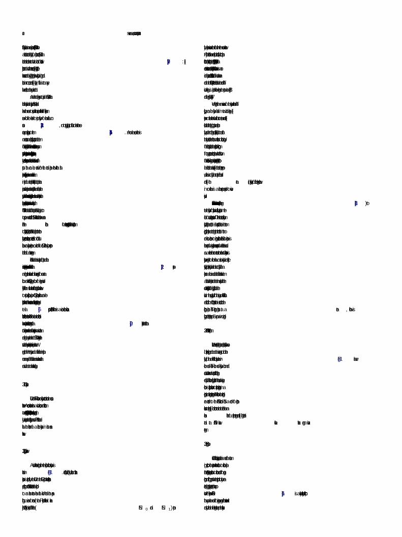
Fig. 4. Cumulatively delay at the four collectors in the presence of competing traf“c causing large delays in the second segment: (a) CN1 shows uniform delays , (b) CN2 alsoregisters a uniform delay, (c) CN3, however, registers large delays, and (d) CN4 registers similar cumulative delays. This identi“es the second segm ent with large delays.
0 100 200 300 400 500 600 700 800 900 1000
1
1.5
2
2.5
3
Pac
ket l
osse
s at
col
lect
or n
odes
Packet id
Loss at CN1 (86 packets lost)
(No loss at CN2)
(No loss at CN3)
(No loss at CN4)
Fig. 5. Loss statistics at four collectors identifying, with the “rst collectorregistering 86 losses. This correlates to an impairment at segment-1.
1 Code available at http://www.cs.ucf.edu/mukundan/netdoctor .
424 M. Venkataraman et al. / Computer Communications 35 (2012) 418…430

0 100 200 300 400 500 600 700 800 900 10000
0.1
0.2
0.3
0.4
0.5
0.6
0.7
0.8
Packet id
Del
ay (
seco
nds)
Collector node 1
0 100 200 300 400 500 600 700 800 900 10000
0.1
0.2
0.3
0.4
0.5
0.6
0.7
0.8
Packet id
Del
ay (
seco
nds)
Collector node 2
0 100 200 300 400 500 600 700 800 900 10000
0.1
0.2
0.3
0.4
0.5
0.6
0.7
0.8
Packet id
Del
ay (
seco
nds)
Collector node 3
0 100 200 300 400 500 600 700 800 900 10000
0.1
0.2
0.3
0.4
0.5
0.6
0.7
0.8
Packet id
Del
ay (
seco
nds)
Collector node 4
Fig. 6. Delay statistics at the four collectors when loss happens at the “rst segment: (a) CN1 varying delay patterns, since the queue at node-1 “lls to maximum leading todrops; (b) CN2, (c) CN3 and (d) CN4. Observe cumulative delays after the “rst segment since there are no competing ”ows in subsequent segments.
Fig. 7. Screen shots of video playout at (a) source, and (b) destination. Notice the intangible output caused by losses of reference frames in the very “rst sec ond of playout.
Table 2Default values and permitted ranges for the parameters [22,24] .
Parameters Default value Permitted range
Mean one-way delay of echo path 0 ms 0…500 msAbsolute delay in echo-free connection 0 ms 0…500 msEquipment impairment factor ( Ie) 0 0…40Random packet-loss probability 0% 0…20%
2 Though the plot in Fig. 8(c) seems to be a straight line, there are very slightvariations of amplitude 0.01 within the line. This is largely because of delay variationsin segment-3 as seen in Fig. 8.
M. Venkataraman et al. / Computer Communications 35 (2012) 418…430 425
Our topology is similar to the simulation testbed ( Fig. 2), with theexclusion of nodes 2, 5 and 7.
7.1. Computing local MOS
To compute MOS, we calculate delay and loss rates, measured asthe average delay and loss per epoch of time. We introduce a live
video stream through our testbed, and calculate MOS in the pres-ence of a VBR competing traf“c, which causes delay and loss inthe intermediate nodes. In Fig. 8(a)…(d), we show the video-MOS(as calculated from Eq. 7) at the four collector nodes.
It is interesting to note the health of individual segments interms of video MOS. Segment-3 intuitively provides a smoothand consistent MOS 2 while segment-1 ( Fig. 8(a)) and segment-4(Fig. 8(d)) register the largest ”uctuations in values. It is easy toobserve from the MOS calculations that loss has a large effect onMOS: the peaks in loss rates have a direct impact in the MOScalculations.

0 5 10 15 20 25 30 350
0.5
1
1.5
2
2.5
3
3.5
4
4.5
5
Vid
eo M
OS
Time epochs
Collector node 1
0 5 10 15 20 25 30 350
0.5
1
1.5
2
2.5
3
3.5
4
4.5
5
Vid
eo M
OS
Time epochs
Collector node 2
0 5 10 15 20 25 30 350
0.5
1
1.5
2
2.5
3
3.5
4
4.5
5
Vid
eo M
OS
Time epochs
Collector node 3
0 5 10 15 20 25 30 350
0.5
1
1.5
2
2.5
3
3.5
4
4.5
5
Vid
eo M
OS
Time epochs
Collector node 4
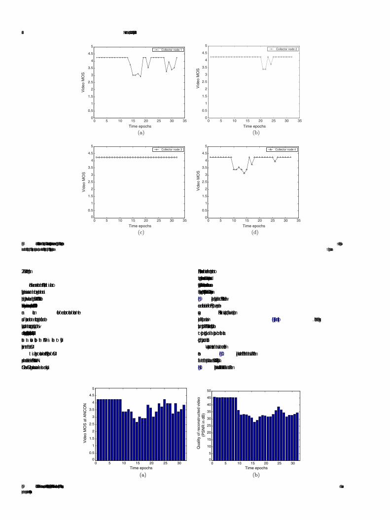
Fig. 8. Local MOS calculations at the four collectors: (a) CN1 shows maximum ”uctuations, especially when loss rates are high, (b) CN2 shows large ”uctuation s at high lossrates around the 22nd epoch, (c) CN3 registers no large ”uctuations and poses a consistent MOS rating, and (d) CN4 analogously registers ”uctuations a t high loss rates.
426 M. Venkataraman et al. / Computer Communications 35 (2012) 418…430
7.2. MOS at correlation platform
Since statistics are streamed to the ANCON node, it is able toglobally correlate various events at all four segments of the datapath. Using this, we calculate a global MOS at ANCON. Unlike col-lectors which only see local events and compute local MOS, ANCONcan cumulate effects of one collector to those of another. In thesense, if packets are lost at a collector segment, its effects can beeasily perceived at the successive segment since quality of the vi-deo has already degraded. Also, equipped with individual MOS pat-terns at various collectors, the ANCON is able to identifyimpairments in term of local MOS.
It is interesting to observe how ANCON•s projection of MOScompares with more established metrics like PSNR. Note that AN-CON calculates MOS using network events like loss and delay.
0 5 10 15 20 25 300
0.5
1
1.5
2
2.5
3
3.5
4
4.5
5
Vid
eo M
OS
at A
NC
ON
Time epochs
Fig. 9. Global MOS for the entire stream as processed at ANCON plotted against PSNR: (a)epochs for direct comparison with ANCON•s projections.
PSNR, however, decodes the received frame and compares that toits corresponding frame at source. Such a direct comparison can di-rectly identify differences in frame content, and this returns a scoreof quality. We plot ANCON•s projection of MOS in various epochs inFig. 9(a), and directly compare this to PSNR values calculated withsource and reference frames. For the PSNR plot, we compute theaverage PSNR values in various epochs (to allow a direct compari-son). The plots are shown in Fig. 9(a) and (b) . Notice the strikingsimilarity in projections. The ANCON was hence successfully ableto project degradations, and this happens much before actualdecoding or playout occurs at destination.
We present two screen-shots of the video at two different in-stances. Fig. 10(a) shows the 75th frame of the video. This framefalls in the 9th time epoch which has a MOS of 4.25757. Similarly,Fig. 10(b) shows the 261th frame. This frame falls in the 28th time
0 5 10 15 20 25 300
5
10
15
20
25
30
35
40
45
50
Qua
lity
of r
econ
stru
cted
vid
eo
(PS
NR
in d
B)
Time epochs
ANCON correlates from various collectors, and (b) PSNR values average d to various
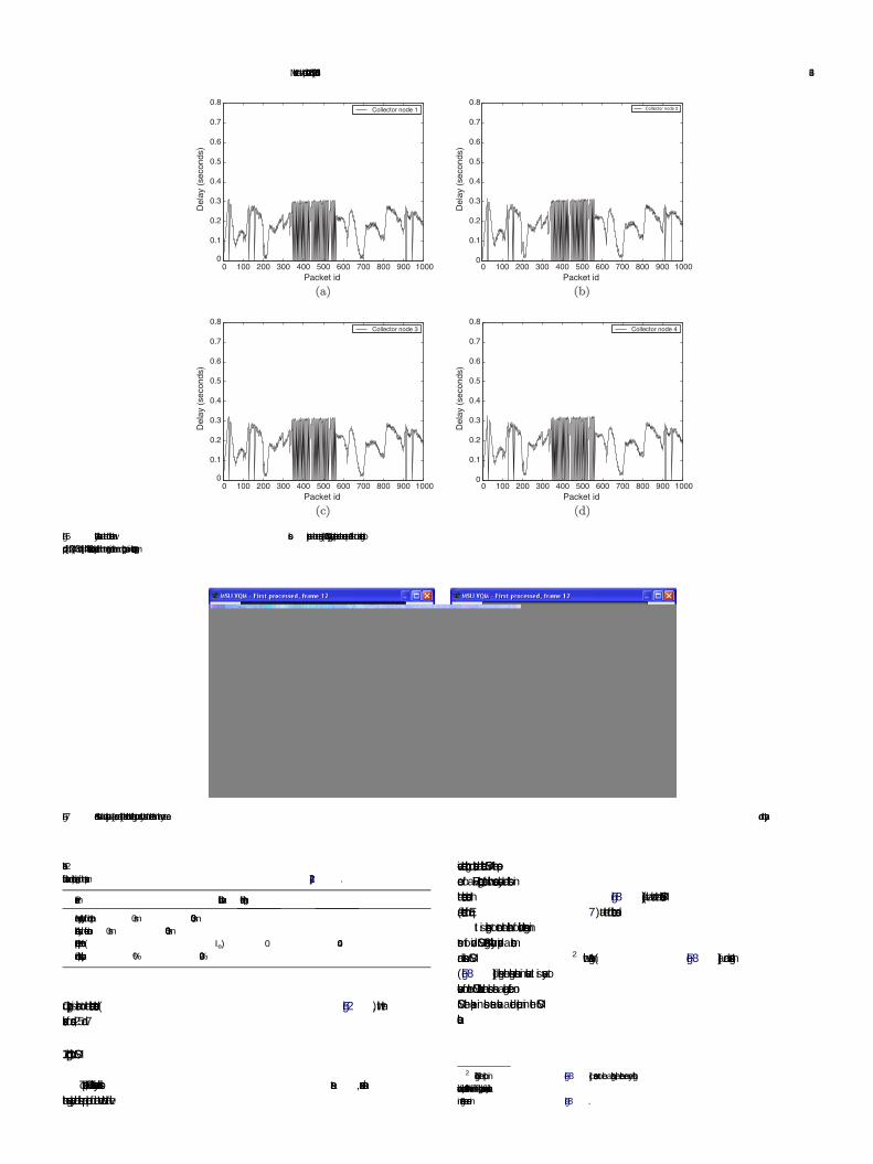
Fig. 10. Processed frames at destination during playout. ANCON could successfully predict playout quality at: (a) Frame-75, when MOS projection was 4.257 (h igher quality),and (b) Frame-261 with slight distortions, when MOS projection was 3.25 (mediocre quality).
M. Venkataraman et al. / Computer Communications 35 (2012) 418…430 427
epoch which has a MOS of 3.250206. As expected, there is a distinctdifference in the quality of the video as predicted by the ANCON.
HeadEnd
E1 E2 E3 E4
STB’s
Collectors
ANCON
Fig. 11. An abstraction of the topology.
8. Overlay stability
Streaming monitorables on an overlay plane orthogonal to thedata-path is emerging as a promising way to monitor, detect andisolate network impairments and outages. However, keeping theoverlay stable and ef“cient poses acute challenges, since theoverlay network itself shall not be monitored for outages. A linearmapping of exporter elements onto collectors often leads to asub-optimum resource allocation, frequently saturating a fewcollectors leading to gaps in monitored data. Such gaps could provecostly for service providers, and a most common reaction to this isexpensive hardware upgrades. In times of such outages, however,it is observed that not all collectors are saturated. More often thannot, balancing the load and ef“ciently distributing availableresources was all that was needed to prevent saturation relatedoutages, and increase overall capacity of the overlay. We discussways to construct a correct, robust, and resilient overlay that canfunction autonomously given the constraints of a typical real worldaccess network.
Serious questions on the feasibility of such an architecturearise:
� How scalable is the architecture with number of data-”ows?� What is the impact of increasing number of exporters on
monitoring?� What is the ideal number of collectors for a given set-up?� What is the service level of this architecture given a blocking
probability?� And “nally, how ef“ciently is traf“c within the overlay
engineered?
8.1. Load allocation and deallocation
We begin with the load allocation and deallocation algorithmthat polices traf“c within the overlay. The resources in an accessnetwork are typically governed by a central entity popularlyknown as the resource manager (RM). As a new ”ow is initiatedfrom the source, the RM makes provisions of bandwidth and otherresources for the new ”ow. Likewise, we vest the load allocationand deallocation to a centralized entity (ANCON), which initiatesthe load allocation algorithm once a new ”ow is introduced inthe network by RM. The load allocation algorithm speci“es whichexporter shall stream statistics about this new ”ow to which avail-
able collector. This allocation is static and the mapping holds untilthe ”ow is deallocated from the network.
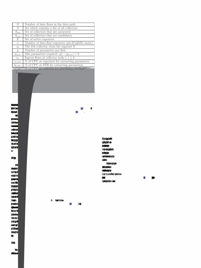
We abstract the loose bunch of exporters as a set E, and the col-lecting bunch of collector nodes as a set S (abstraction in Fig. 11).The exporter pool shows a variation in number captured by the fol-lowing equation:
E¼ Eþ si
which states that with an inception of a new ”ow, a new set-top-box (si) is initiated as an exporter, and is subsequently added tothe list E. Similarly, the set S denotes the set of all collector nodesin the topology. The elements of set S make up two other sets,Ssaturated and Scandidate, the set of collectors that are saturated andthe set of collectors which are potential candidates for traf“cmapping. Consequently, the following holds:
S¼ Ssaturated þ Scandidate
The set Scandidate is equivalent to the set S when the networkboots up, since no collector is saturated. The RM initiates requestsfor new ”ows, and the ANCON “res the mapping algorithm. The ex-porter list is updated to re”ect the set-top-box associated with thenew ”ow.
The task of the allocation algorithm is to arrive at a mapping be-tween exporters and collectors for every new ”ow. The algorithmscans every exporter, and determines a collector for the given ex-porter. The list of collectors are scanned to ensure that a collectorhas minimum requirements for bandwidth and CPU for a maxi-mum of p parameters. Note that, to be selected, all three axes mustbe resolved, while saturation of any one moves it to the saturationlist. In case the loading is heavy and no suitable collectors arefound, the algorithm is recursively run for reduced number ofparameters until the number reaches pmin. For each selected

0 5 10 15 20 250
0.1
0.2
0.3
0.4
0.5
0.6
0.7
0.8
0.9
1
Del
iver
y R
atio
Number of Collectors 1 2 3 4 5
x 10−4
0.1
0.2
0.3
0.4
0.5
0.6
0.7
0.8
0.9
1
Blo
ckin
g P
roba
bilit
y
Sending Frequency
E=50E=35E=80E=65E=20
10 20 30 40 50 60 70 80 900.5
1
1.5
2
2.5
Sam
plin
g F
requ
ency
Number of exporters 0 5 10 15 20 25
0
0.5
1
1.5
2
2.5
Pac
kets
ser
vice
d
Collector ID
x 104
Fig. 15. (a) Delivery ratio versus number of collectors, for a given set of 50 exporters; (b) Blocking probability against source rate and number of exporters; (c) Sampling rateagainst number of active exporters, for a blocking probability of less than 0.2; (d) Distribution of number of packets serviced by a collector, for a ca se of 25 collectors.
M. Venkataraman et al. / Computer Communications 35 (2012) 418…430 429
then drops in a non-increasing fashion. This clearly establishes thatthere is a particular number of collectors that are indeed optimumfor a given set of exporters. Upon extensive investigation with var-ious other values, we offer this following guideline as a simple ruleof thumb. The optimum number of collectors is roughly one-tenththe number of active exporters within an access network.
8.4. Monitoring gaps: specifying minimum requirements
Blocking probability is de“ned as the probability that the de-manded service is blocked, averaged over a suf“ciently long inter-val of time. In our case, it is the probability that a monitoredinformation is lost in the overlay before it makes it to ANCON.What is ideally required is a form of quality assurance: given arequirement that the blocking probability be less than a certain va-lue, what is the right number of exporters for such a set-up.
To understand the nature of sampling on the number of export-ers for a given threshold of, we “rst understand the behavior ofblocking itself for a given streaming rate. We conducted an exper-iment where we measured the blocking probability for a rising rateof monitoring at exporters. We choose a suf“ciently large numberof packets (5,00,000) over a 6 h long simulation period to under-stand the nature of blocking within the overlay. We run eachexperiment for different set of collectors at least 10 times tosmoothen out variations in performance. Shown in Fig. 15(b),blocking probability for any given set of exporters increases shar-ply with a slight increase in streaming rate. The value, however,stabilizes with further increase in the streaming rate, almost hit-ting a saturation beyond a certain point.
Given such a behavior, we now apply quality assurance. We ask:what is the sampling frequency at ANCON if a service provider de-mands a blocking probability of less than 0.2 (i.e., at least 80% ofmonitorables should be received and processed at ANCON). We
draw a horizontal line across the plot in Fig. 15(b) at around the va-lue of 0.2 for blocking probability, and subsequently measure thecorrect sampling frequency given the maximum blockingprobability.
The sampling frequency for such a case for various values ofexporters is as shown in Fig. 15(c). The curve exhibits a parabolictrend, with the rate falling more steeply beyond a certain point(in this case, for E> 50). This study implies a few properties of thisoverlay: (i) it is possible to specify design with maximum blockingprobability in mind, since there is an optimum number of export-ers all blocking probabilities, (ii) there is an optimum number ofcollectors given a set of exporters; and, (iii) buffer sizes, andincreasing them to improve capacity, does not necessarily workvery well.
8.5. Comparing load allocation to randomized allocation
Having studied the nature and dynamics of the overlay, we “-nally turn our attention to ensuring a balanced load distribution gi-ven the following: (i) a maximum blocking probability demanded,or in other words, a minimum quality assurance in monitoring, (ii)a correct set of exporters for such a case, and (iii) the correct set ofcollectors for this set-up. Having established the “rst three require-ments in the previous sections, we now run our load-balancingalgorithm to study the variations in load distribution across vari-ous collectors for a given set of 250 exporters, 25 collectors, a mon-itoring rate of 1 packet every 5 s per ”ow, for a set of 1000 ”ows.The simulation runs reported here run for a total of approximately5,00,000 packets, for a simulation time of 6 h. For 25 collectors, thismeans that a perfectly distributed load would result in approxi-mately 20,000 packets serviced per collector. The plot for thisexperiment is as shown in Fig. 15(d). We run our load distributionalgorithm as ”ows arrive and depart ( Fig. 13), and measure the
430 M. Venkataraman et al. / Computer Communications 35 (2012) 418…430
actual number of packets serviced by every collector. As can beseen, the variance of load distribution is nearly minimum. Whileit is theoretically impossible to achieve a perfectly balanced sys-tem, our algorithm outperforms other schemes (like random allo-cation or a round-robin allocation), both in terms of loaddistribution as well as maximizing delivery ratio.
9. Conclusions
Given the stringent delivery bounds of streaming applications,there is a need to arrest network induced errors as they occur. Thiswould naturally be the fastest way to isolate, react, and adapt tochanging network conditions. In this paper, we successfully designand evaluate an architecture of a hierarchical overlay of ••collector••nodes that can gather and disseminate network statistics. The col-lectors are decentralized, and can monitor the health of local seg-ments. The statistics are routed to a root node, called ANCON,that correlates and computes various properties of the video ”ow.
Using such a network of collectors, we are able to: (i) isolatenetwork induced causes of a degradation; (ii) isolate segments/subnets in the network that caused the impairment, (iii) provisionlocal feedbacks, and inform source in real time of network statis-tics, (iv) create an instrumentation layer above the data plane thatcan correlate network statistics and compute MOS, (v) export localMOS to service providers instead of overwhelming them with net-work statistics, to better facilitate root cause analysis, (vi) showthat quality can be scored continuously along the data path, and,(vii) predict the quality of a video much before the playout actuallyoccurs at destination. Our evaluation of the design with extensiveexperiments establishes feasibility of the architecture. This studyalso identi“es key knobs that should be exported to service provid-ers to help them self tune the architecture, as well as key parame-ters that a collector nodes should monitor.
References
[1] Y. Amir, C. Danilov, S. Goose, D. Hedqvist, A. Terzis, An overlay architecture forhigh quality VoIP streams, IEEE Trans. Multimedia 8 (6) (2006) 1250…1262.
[2] D.G. Andersen, H. Balakrishnan, M.F. Kaashoek, R. Morris, Resilient overlaynetworks, in: Proc. 18th ACM SOSP, 2001.
[3] P. Calhoun, DIAMETER Base Protocol, IETF FRC 3588, 2003.[4] D. Chandler, S.S. Hemami, Effects of natural images on the detectability of
simple and compound wavelet subband quantization distortion, J. Opt. Soc.Am. 20 (7) (2003) 1164…1180.
[5] P. Calhoun, DIAMETER Base Protocol, IETF FRC 3588, 2003.[6] Y.C. Huang, C.S. Lu, H.K. Wu, JitterPath: probing noise resilient one-way delay
jitter-based available bandwidth estimation, IEEE Trans. Multimedia 9 (4)(2007) 798…812.
[7] S. Kanumuri, P.C. Cosman, A.R. Reibman, V.A. Vaishampayan, Modeling packet-loss visibility in MPEG-2 video, IEEE Trans. Multimedia 8 (2006) 341…355.
[8] J. Klaue, B. Rathke, A. Wolisz, EvalVid-A framework for video transmission andquality evaluation, in: Proceedings of the 13th International Conference onModeling Techniques and Tools for Computer Performance Evaluation, IL,September 2003.
[9] R. Koenen, Overview of the MPEG-4 Standard, ISO IEC JTCI.SC29/WG11 M4030,2001.
[10] N. Miller, P. Steenkiste, Collecting network status information for network-aware applications, IEEE Infocom (2000).
[11] S. Mohamed, G. Rubino, A study of realtime packet video quality using randomneural networks, IEEE Trans. Circ. Syst. Video Technol. 12 (12) (2002) 1071…1083.
[12] M.S. Moore, J.M. Foley, S.K. Mitra, Detectability and annoyance value of MPEG-2 artifacts inserted into uncompressed video sequences, in: Proceedings ofSPIE, Human Vision and Electronic Imaging V, vol. 3959, San Jose, CA, January2000, pp. 99…110.
[13] M.S. Moore, S.K. Mitra, J.M. Foley, Defect visibility and content importanceimplications for the design of an objective video “delity metric, Proc. IEEE ICIP3 (2002) 45…48.
[14] J. Postel, Transmission Control Protocol, IETF RFC 793, September 1981.[15] M.G. Ramos, S.S. Hemami, Suprathreshold wavelet co-ef“cient quantization in
complex stimuli: pshychophysical evaluation and analysis, J. Opt. Soc. Am. 20(7) (2003) 1164…1180.
[16] C. Rigney, S. Willens, A. Rubens, W. Simpson, Remote Authentication Dial InUser Services (RADIUS), IETF RFC 2865, 2000.
[17] R. Stewart, Stream Control Transmission Protocol, IETF RFC 2960, 2000.[18] M. Venkataraman, S. Sengupta, M. Chatterjee, R. Neogi, Towards a Video-QoE
de“nition in converged networks, in: Second International Conference onDigital Telecommunications, ICDT, Silicon Valley, CA, July 2007.
[19] A. Watson, M.A. Sasse, Measuring perceived quality of speech and video inmultimedia conferencing applications, Proc. ACM Int. Conf. Multimedia (1998)55…60.
[20] X. Yang, C. Zhu, Z.G. Li, X. Lin, N. Ling, An unequal packet loss resilience schemefor video over the Internet, IEEE Trans. Multimedia 7 (4) (2005) 753…765.
[21] P. Zhu, W. Zhen, C. Li, Joint design of source rate control and QoS-awarecongestion control for video streaming over the internet, IEEE Trans.Multimedia 9 (2) (2007) 366…376.
[22] ITU-T Recommendation G.107, The E-Model, a computational model for use intransmission planning, December 1998, Subjective video quality assessmentmethods for multimedia applications, Septenber 1999.
[23] ITU-R BT.500-8, Methodology for the subjective assessment of the quality oftelevision pictures, 1998.
[24] ITU-T Recommendation P.910, Subjective video quality assessment methodsfor multimedia applications, September 1999.
[25] The Network Simulator v2.30. <http://www.isi.edu/nsnam/ns> .[26] Internet Protocol Detail Record. <http://www.ipdr.org> .[27] The IPDR/SP (Streaming Protocol) Speci“cations. <http://ipdr.org/download-
docs/protocol.html> .[28] Video Evaluation Toolkit, Moscow State University, Moscow, Russia. <http://
graphics.cs.msu.su/>. Available for free download.