designing a lorentz force actuator for a robotic tuna
TRANSCRIPT
Designing a Lorentz Force Actuatorfor a Robotic Tuna
Justin PohSpring, 2015
Under the guidance ofProfessor David Barrett
Supported by:Student Academic Grant (SAG)
Franklin W. Olin College of Engineering
Intelligent Vehicles LaboratoryFranklin W. Olin College of Engineering
Needham, Massachusetts
Contents
1 The Olin Robotic Tuna Research Project . . . . . . . . . . . . 11.1 Introduction to the Olin Robotic Tuna Research Project 11.2 Why a Tuna? . . . . . . . . . . . . . . . . . . . . . . . 1
2 The Current Robotic Tuna . . . . . . . . . . . . . . . . . . . . 33 Increasing Propulsion Efficiency . . . . . . . . . . . . . . . . . 5
3.1 Magnetism and Lorentz Forces . . . . . . . . . . . . . . 53.2 Efficiency . . . . . . . . . . . . . . . . . . . . . . . . . 6
4 Actuator Design . . . . . . . . . . . . . . . . . . . . . . . . . . 94.1 Desired Motion and Proposed Control Scheme . . . . . 104.2 Overview of the Mechanical Design . . . . . . . . . . . 124.3 The Iron Core . . . . . . . . . . . . . . . . . . . . . . . 134.4 The Voice Coil . . . . . . . . . . . . . . . . . . . . . . 144.5 The Actuator Arm . . . . . . . . . . . . . . . . . . . . 164.6 The Test Stand . . . . . . . . . . . . . . . . . . . . . . 164.7 Electrical System and Data Collection . . . . . . . . . 18
5 Conclusion and Future Work . . . . . . . . . . . . . . . . . . . 196 Acknowledgments . . . . . . . . . . . . . . . . . . . . . . . . . 19
i

List of Figures
1 Vortices along the body of a tuna . . . . . . . . . . . . . . . . 22 Vortex shedding from the tail of a fish . . . . . . . . . . . . . 33 The current version of the robotic tuna . . . . . . . . . . . . . 34 Views of the tail section of the current version of the robotic
tuna . . . . . . . . . . . . . . . . . . . . . . . . . . . . . . . . 45 Close-up views of the servo that delivers propulsion power
(left) and the servo that aids in steering (right) . . . . . . . . 46 Diagram of a simple wire placed in a magnetic field . . . . . . 67 Field lines of a magnet in free air . . . . . . . . . . . . . . . . 78 Diagram of magnetic circuit in a ferrous material . . . . . . . 89 Diagram of a Hard Disk Drive Arm . . . . . . . . . . . . . . . 910 Conceptualized velocity-position plot of the actuator as it os-
cillates. . . . . . . . . . . . . . . . . . . . . . . . . . . . . . . . 1011 Velocity-position plots of the actuator oscillation with the ve-
locity impulse delivered at different points . . . . . . . . . . . 1112 Render of the prototype actuator . . . . . . . . . . . . . . . . 1213 Exploded view of the iron core . . . . . . . . . . . . . . . . . . 1314 Picture of the voice coil around which the magnet wire will be
wound . . . . . . . . . . . . . . . . . . . . . . . . . . . . . . . 1515 Picture of the actuator arm with the voice coil mounted to it. 1616 Two different views of the test stand with labeled parts . . . . 1717 Exploded view of the test stand . . . . . . . . . . . . . . . . . 17
ii

1 The Olin Robotic Tuna Research Project
1.1 Introduction to the Olin Robotic Tuna ResearchProject
The long-term goal of the Olin Robotic Tuna research project is to design arobotic tuna capable of completing a trans-atlantic voyage. To achieve thisgoal, the project has been divided up into three phases, starting with a one-man launchable robotic tuna and ending with a much larger version capableof housing the required infrastructure for a long trans-atlantic voyage.
The project is currently still in phase 1. Last summer (summer 2014), wedeveloped a proof of concept version of the robotic tuna to prove that ouractuation concept was feasible. In the fall of 2014, we then proceeded to de-velop some of the software required for autonomous operation of the robotictuna. This semester, we refocused our research efforts on designing a moreefficient verison of the propulsion system for the robotic tuna.
1.2 Why a Tuna?
The main reason for designing a robotic tuna is propulsion efficiency. Bi-ological tuna fish have a highly efficient method of propulsion that wastesvery little energy compared to any existing method of propulsion used on seavessels today. This efficiency is achieved through several key modifications:
1. Eliminating Water Rotation
Despite the wide variety of boat propellers and motors available, most con-ventional water propulsion methods essentially rely on a spinning propellerpushing water out the back of the sea vessel in order to propel the sea ves-sel forward. While this is a great propulsion method, the use of propellersmeans that, in addition to pushing water out behind the sea vessel, the wateris also being rotated in the vertical plane by virtue of being in contact withthe rotating propeller blades. However, to propel a sea vessel forward, theonly motion that matters is the straight motion of the water out the back ofthe vessel. This means that all the energy that is spent to rotate the wateris wasted energy since the rotational motion is unnecessary.
In a biological tuna, however, there is no such rotation of the water andso the tuna immediately gains this energy saving.
1

2. Vortex Manipulation
The second, and more intriguing, reason that a tuna can achieve such highpropulsion efficiency is that a tuna detects and manipulates vortices occuringaround it in order to increase the propulsion forces acting on it.
As a tuna swims through the water, small swirls of water, known as vor-tices, are generated that travel down the side of its body as shown in thefigure below:
Figure 1: Vortices along the body of a tuna
When these vortices reach the tail, the tuna positions its tail appropriatelysuch that the tail is in the correct position to be pushed on by the vorticesas the vortices leaves the tail of the tuna. This allows the tuna to gainadditional propulsion from these vortices. The following diagram1 illustratesthis:
1Diagram from Triatafyllou, M. S. & Triatafyllou, G. S. (1995). An Efficient SwimmingMachine, Scientific American, 272.3, 64-71
2

Figure 2: Vortex shedding from the tail of a fish
Thus, because the tuna is capable of making use of the movement of the wateraround it to achieve additional propulsion, it is able to further reduce theamount of energy that is wasted in water movement that does not contributeto propulsion.
2 The Current Robotic Tuna
The current robotic tuna is shown in the figure below:
Figure 3: The current version of the robotic tuna
For the research this semester, we were particularly interested in the efficiencyof the propulsion system for the fish. The propulsion system designed in the
3

summer of 2014 is shown in the figures below:
(a) The whole tail section(b) Close-up view of the two servos pow-ering the tail section
Figure 4: Views of the tail section of the current version of the robotic tuna
(a) Propulsion servo (b) Steering Servo
Figure 5: Close-up views of the servo that delivers propulsion power (left)and the servo that aids in steering (right)
In essence, the tail designed in the summer of 2014 had two servos poweringit. One servo was mounted to the base of the tail and this servo served as themain source of power for propelling the fish forward. This servo essentiallyperformed the function of a propeller on a typical boat. The other servo was
4

mounted in the fourth section of the tail and was used to control only thelast three sections of the tail to help steer the fish where necessary. Thisservo essentially performed the function of a ruder on a typical boat.
Although this design was useful as a proof-of-concept, using the servos inthis manner is extremely inefficient. As such, in order to advance toward thegoal of a highly efficient robotic tuna, we wanted to design a significantlymore efficient tail.
3 Increasing Propulsion Efficiency
To begin designing a more efficient propulsion system, we first began by com-paring the way a biological tuna generates propulsion to the way the currentrobotic tuna achieves propulsion to figure out where the largest mechanicallosses were present. As a result, we realized that, unlike the biological fish,the robotic tuna must continue to supply energy to oscillate its tail. It istherefore unable to take advantage of resonance and natural frequencies ofvibration to reduce the amount of energy required to sustain the oscillation ofits tail. For this reason, we concluded that traditional methods of actuationthat relied on contact forces would not be suitable because such actuationmethods would not be capable of being ”uncoupled” in order to allow thetail to achieve resonance. To solve this problem, we turned to magnetismand lorentz force actuators.
3.1 Magnetism and Lorentz Forces
Lorentz force is the force that a charged particle will experience when it isplaced in a magnetic or electromagnetic field. Equally, what this means isthat a wire or a coil of wire will also experience a force when a magnetic fieldis applied across it. A diagram of a simple set up with a wire placed in anapplied magnetic field is shown in the figure below2:
2Diagram obtained from http://www.antonine-education.co.uk/Pages/Physics_
4/Magnetism/MAG_01/mag_field_1.htm
5
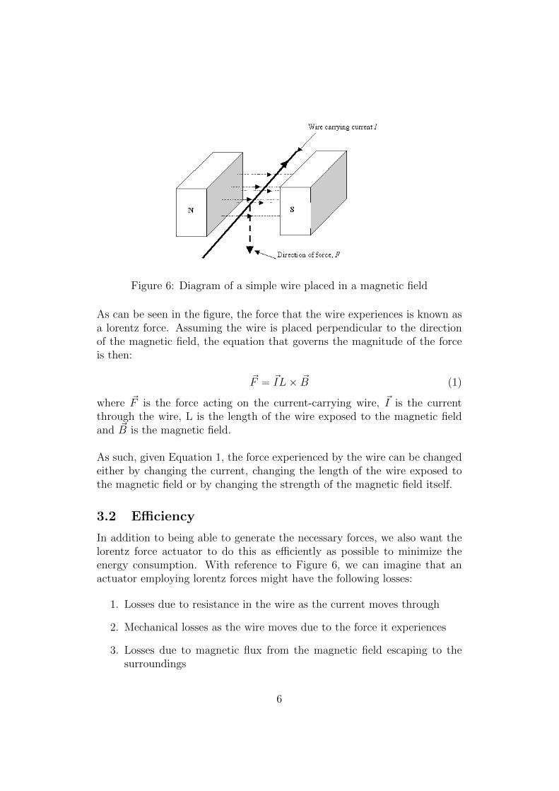
Figure 6: Diagram of a simple wire placed in a magnetic field
As can be seen in the figure, the force that the wire experiences is known asa lorentz force. Assuming the wire is placed perpendicular to the directionof the magnetic field, the equation that governs the magnitude of the forceis then:
~F = ~IL× ~B (1)
where ~F is the force acting on the current-carrying wire, ~I is the currentthrough the wire, L is the length of the wire exposed to the magnetic fieldand ~B is the magnetic field.
As such, given Equation 1, the force experienced by the wire can be changedeither by changing the current, changing the length of the wire exposed tothe magnetic field or by changing the strength of the magnetic field itself.
3.2 Efficiency
In addition to being able to generate the necessary forces, we also want thelorentz force actuator to do this as efficiently as possible to minimize theenergy consumption. With reference to Figure 6, we can imagine that anactuator employing lorentz forces might have the following losses:
1. Losses due to resistance in the wire as the current moves through
2. Mechanical losses as the wire moves due to the force it experiences
3. Losses due to magnetic flux from the magnetic field escaping to thesurroundings
6

Losses in the wire and mechanical losses are almost unavoidable and aretypically relatively small. As such, we turn our attention to losses due tomagnetic flux escaping into the surroundings.
Since lorentz force actuators require a magnetic force in order to function,the magnetic field is a source of energy for the actuator. As such, whenmagnetic flux is lost to the surroundings, we are essentially losing energy tothe surroundings that could have been used to do useful work in moving thewire. In order to minimize these losses, it is therefore important to ensurethat the magnetic flux is contained and only allowed to escape across the airgap where the force needs to be generated. In this way, loss of magnetic fluxto the surroundings is minimized.
As it turns out, the most common method of containing magnetic flux isto create what is known as a magnetic circuit. Just as a typical electricalcircuit has electrons flowing through it, a magnetic circuit has magnetic fluxflowing through it. A typical magnet placed in air will have magnetic fieldlines around it as shown in the figure below3:
Figure 7: Field lines of a magnet in free air
As can be seen in Figure 7, when a magnet is left in air, the magnetic fieldlines form loops that get larger the further they are away from the magnet. Assuch, magnetic flux is being freely lost into the environment when a magnetis left in air and this is all lost energy. We can minimize this lost magneticflux by placing a ferrous material such as iron near the magnet such that thefield lines will preferentially enter the ferrous material instead of being lostto the environment as shown in the figure below4:
3Diagram obtained from http://physics.stackexchange.com/questions/143119/
why-in-a-solenoid-do-the-magnetic-field-lines-resemble-that-of-a-bar-magnet4Diagram obtained from http://www.globalspec.com/reference/81215/203279/
1-22-magnetic-circuits
7

Figure 8: Diagram of magnetic circuit in a ferrous material
As can be seen in Figure 8, there is much less magnetic flux lost to theenvironment because it is now contained within the ferrous material. We canthen take advantage of this mganetic circuit in a lorentz force actuator bycutting a hole out of the loop formed by the ferrous material and allowing themagnetic flux to flow across that air gap. By doing this, we have maximizedthe magnetic field strength across the air gap. Therefore, if we place acurrent carrying wire in the air gap, we will have maximized the lorentzforce experienecd by that wire.
8

4 Actuator Design
For our design, we were inspired by the design of hard disk arm actuators.An image of one is shown below5:
Figure 9: Diagram of a Hard Disk Drive Arm
As can be seen in the figure above, the voice coil is a coil of magnet wirethrough which a current is passed. The voice coil then sits between a pairof magnets, one positioned above and one positioned below the voice coil.These magnets thus apply a magnetic field across the voice coil. When acurrent is passed through the voice coil, the voice coil experiences a forcewhich causes it to pivot around the actuator axis and move the arm.
This seemed to be a good concept for what we expected for the actuatorfor the fish. The oscilating back and forth motion needed to actuate thesections of the tuna tail could be achieved by swinging the arm back andforth. However, we now needed to figure out how to design such an actuatorto be as efficient as possible.
5Image from http://www.kepcil.com/kepcilin/harddisk/hdslider/bigcoil1.jpg
9

4.1 Desired Motion and Proposed Control Scheme
The design of the actuator began with deciding on the desired motion wewant to achieve and how the control system could be designed to achievethis. For this prototype, the goal was to design an actuator that would allowthe actuator arm to oscillate back and forth in a rotary motion. Doing sowould therefore allow us to attach the oscillating part of the actuator to asection of the fish tail and therefore oscillate the tail.
In terms of the control scheme, one can imagine that this desired motionis similar to a child on a swing. The child rides on the swing by swingingback and forth in essentially an oscillatory motion. In order to keep theswing moving, the child must deliver impulses of velocity at some point inthe motion by swinging their legs out. Therefore, for the actuator to achievesustained oscillatory motion, it too must deliver impulses of velocity at somepoint in its oscillatory motion.
In terms of a control scheme, however, the key question is when duringthe oscillation does the impulse of velocity need to occur? To answer thisquestion consider the velocity-position plot of the motion as shown in thefigure below:
Figure 10: Conceptualized velocity-position plot of the actuator as it oscil-lates.
As can be seen in Figure 10, after starting at some initial position with someinitial velocity at t=0, frictional and other losses will cause the oscillation todecrease in amplitude, assuming no external force is applied to restore theoscillation. As such, the circle traced on the velocity-position plot will shrinkin radius as shown by the circle labeled t>0.
To apply a restoring force, one could imagine that the two positions that
10

would allow the velocity impulse to have the largest impact on the motionare:
1. Deliver the velocity impulse at equilibrium position where position iszero and velocity is maximum; or
2. Deliver the velocity impulse at the extreme positions where velocity iszero and posiiton is maximum
The effects of each possible choice are shown in the graphs below:
(a) Velocity impulse delivered atmaximum position, zero velocity.
(b) Velocity impulse delivered atmaximum velocity, equilibrium position.
Figure 11: Velocity-position plots of the actuator oscillation with the velocityimpulse delivered at different points
As can be seen in the above figure, applying the velocity impulse at theequilibrium position results in the largest change in oscillation. As such, inthe mechanical design of this actuator, the magnets should be placed at theequilibrium position of the oscillation in order to be able to deliver a pulseof velocity at equilibrium to sustain the oscillation.
11

4.2 Overview of the Mechanical Design
The prototype of the actuator designed during this research period is shownin the figure below:
Figure 12: Render of the prototype actuator
The actuator has four main mechanical components:
1. The iron core, which consists of three pieces: the upper frame, themagnetic shield and the lower frame. The purpose of the iron core is tocontain the magnetic flux within it and minimize the loss of magneticflux into the surroundings.
2. The voice coil spool that will hold the magnet wire voice coil. Whencurrent is passed through that magnet wire, a resulting force will acton the voice coil spool.
3. The actuator arm that holds the voice coil spool. When current isapplied to the voice coil, the force experienced by the voice coil spoolwill move the arm and cause it to swing back and forth
4. The test stand in this prototype represents the supporting structurethat will be needed to mount the components that make up the actu-ator.
The following sections will now explain the design of each component indetail.
12

4.3 The Iron Core
The iron core is one of the most important components in the actuator andthe actuator could not function without it. As discussed in section 3.2, inorder to for the actuator to be as efficient as possible, there must be a loopof ferrous material that is able to capture the magnetic flux produced by themagnet in order to contain it and concentrate it across the air gap where itis required. This minimizes the energy losses to the environment. As such,the iron core makes up part of the structure of the actuator and the magnetsthat will be used to generate a magnetic field are mounted to this iron core.The figure below shows this configuration:
Figure 13: Exploded view of the iron core
As can be seen in Figure 13, the loop of ferrous material that contains themagnetic circuit is made up of the upper frame, shielding plate and lowerframe. The magnets that provide the magnetic flux for the system are thenmounted to the upper and lower frame and the voice coil fits around theshielding plate. With this configuration, the magnetic flux from the magnetcrosses the air gap either between either the upper frame and shielding plateor between the lower frame and shielding plate. Either way, the flux then endsup in the lower shielding plate where it can then travel back around to theupper or lower frame to form a complete magnetic circuit. As a result, thisdesign should concentrate the magnetic flux in the air gap where the voicecoil will be located to maximize the force generated. In addition, because themagnets are mounted on the interior of the iron core, the loss of magneticflux to the surroundings should be minimized.
13

4.4 The Voice Coil
In this prototype, the dimensions of the voice coil were designed such thatthe lorentz force generated was enough to counteract the springs that arebeing used to provide restoring force (see section 4.5 for more details on howsprings are involved in the design). As such, it was necessary to calculatethe dimensions of the voice coil in order to ensure that the actuator wouldwork as expected.
To start, the table below lists some of the system parameters that havebeen set and cannot be changed:
Parameter Description Parameter ValueMaximum Spring Force 0.76lbf ≈ 3.4NLength of Voice Coil Exposed to Magnetic Field 2.54cm = 0.0254mMagnetic Field Generated by Magnets 6000 Gauss ≈ 0.6 Tesla
Table 1: Table of set parameters for the voice coil
Using Equation 1, we can then express the force equation as follows:
~F = 3.4 = (0.6)(0.0254)NI (2)
where N is the number of turns on the coil and I is the current flowing throughthe magnet wire that will be wound around the voice coil holder.
Thus,
NI =3.4
(0.6)(0.0254)≈ 223.1 (3)
Therefore, we have two factors in the design of the voice coil that we canmanipulate: the number of turns on the voice coil and the current flowingthrough it. However, the magnet wire has a fixed maximum current ratingthat should not be exceeded so we do not have absolute freedom over thatparameter.
For this prototype, we are using 20AWG wire which has a maximum cur-rent rating of 11 amps under chassis wiring conditions (exposed to air tocool). Given that we want a Factor of Safety (FOS) of 2, therefore, themaximum current load through the wire should be:
Amax =11
2≈ 5.5A (4)
14

Given that maximum current rating, the number of turns needed to generatesufficient force is:
N =223.1
5.5≈ 41 turns (5)
Therefore, to add additional FOS, we should use 50 turns in the voice coil.
Using this, we can now calculate physical dimensions of the holder aroundwhich the magnet wire will be wound. 20 AWG magnet wire has a wirediameter of 0.032in. If 50 turns were laid out in one single row, the lengthwould be 50(0.032) = 1.6in. This would be a ridiculous width given the di-mensions of the rest of the prototype. However, we can stack multiple layersof coils. As such, if we use a two-layer configuration, the width required forthe voice coil holder is now only 0.8 inches, which is much more reasonable.To avoid too tight a fit, the voice coil holder has therefore been designed tobe 0.9 inches wide. The other dimensions for the voice coil holder are thenset by the mechanial design of the rest of the actuator.
A picture of the voice coil is shown below:
Figure 14: Picture of the voice coil around which the magnet wire will bewound
15
4.5 The Actuator Arm
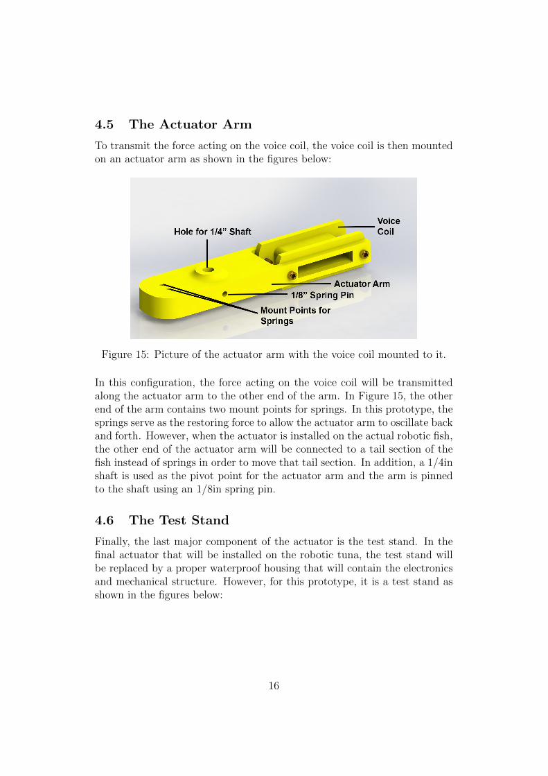
To transmit the force acting on the voice coil, the voice coil is then mountedon an actuator arm as shown in the figures below:
Figure 15: Picture of the actuator arm with the voice coil mounted to it.
In this configuration, the force acting on the voice coil will be transmittedalong the actuator arm to the other end of the arm. In Figure 15, the otherend of the arm contains two mount points for springs. In this prototype, thesprings serve as the restoring force to allow the actuator arm to oscillate backand forth. However, when the actuator is installed on the actual robotic fish,the other end of the actuator arm will be connected to a tail section of thefish instead of springs in order to move that tail section. In addition, a 1/4inshaft is used as the pivot point for the actuator arm and the arm is pinnedto the shaft using an 1/8in spring pin.
4.6 The Test Stand
Finally, the last major component of the actuator is the test stand. In thefinal actuator that will be installed on the robotic tuna, the test stand willbe replaced by a proper waterproof housing that will contain the electronicsand mechanical structure. However, for this prototype, it is a test stand asshown in the figures below:
16
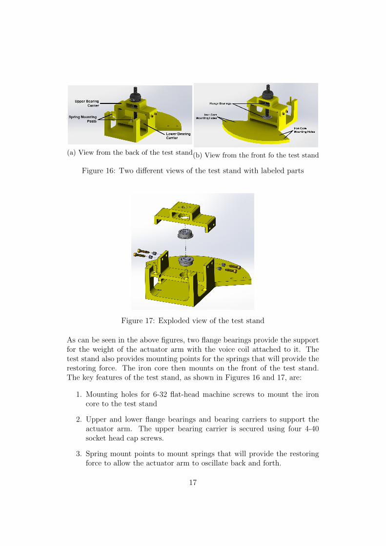
(a) View from the back of the test stand(b) View from the front fo the test stand
Figure 16: Two different views of the test stand with labeled parts
Figure 17: Exploded view of the test stand
As can be seen in the above figures, two flange bearings provide the supportfor the weight of the actuator arm with the voice coil attached to it. Thetest stand also provides mounting points for the springs that will provide therestoring force. The iron core then mounts on the front of the test stand.The key features of the test stand, as shown in Figures 16 and 17, are:
1. Mounting holes for 6-32 flat-head machine screws to mount the ironcore to the test stand
2. Upper and lower flange bearings and bearing carriers to support theactuator arm. The upper bearing carrier is secured using four 4-40socket head cap screws.
3. Spring mount points to mount springs that will provide the restoringforce to allow the actuator arm to oscillate back and forth.
17

4.7 Electrical System and Data Collection
In addition to the mechanical design, in order for this prototype to actuallyfunction and be useful, it needs an electrical system and a way to collect data.
Given the mechanical design discussed above and the desired control scheme,the electrical system must be capable of delivering a current impulse to thevoice coil at the point when the actuator arm is at the equilibrium position.To do this, the actuator must be able to:
1. Detect when the actuator arm is at the equilibrium position
2. Trigger a relatively large current impulse using a relatively low currentand voltage signal
As such, although not fully designed, the electrical system consists of thefollowing components:
1. A rotary encoder to detect the position of the actuator arm. For thisprototype, we are using a US Digital E4T-250-250-S-H-D-2 rotary en-coder.
2. A microcontroller such as an arduino or NI myRIO
3. A solid-state relay rated for at least a 12A throughput current
4. Power supply also rated for at least 12A of throughput current
With these components, the concept is that the rotary encoder will bemounted on top of the upper bearing carrier as shown in Figure 16. Therotary encoder can then provide position information. Using this informa-tion, velocity can be calculated in order to plot the velocity-position plot.This information can also be used by the microcontroller to detect whenthe arm is at the equilibrium position. The microcontroller can then emita ”True” voltage (typically a 5V signal) to the solid-state relay in order totrigger the current impulse required to generate a lorentz force acting on thevoice coil. This system, however, has not been tested and future work willinclude testing this electrical system to determine its efficacy.
18

5 Conclusion and Future Work
In conclusion, the goal for research on the robotic tuna this semester was todesign a more efficient propulsion system for the tail of the robotic tuna inorder to achieve greater propulsion efficiency. By designing an actuator thatrelies on lorentz forces, we believe that the robotic tuna will be extremelyefficient because it is able to harness natural phenomena such as resonanceand vortex shedding in order to increase its propulsion efficiency substatially.
Although the actuator has been designed, it has not actually been proto-typed or tested. As such, future work on this project will include prototypingand testing the design to determine its efficiency as well as force-generatingcapacity. The actuator then needs to be scaled down in size in order to beof appropriate size and weight to be used in the actual robotic fish.
6 Acknowledgments
This research would not have been possible without the help of several facultymembers at Olin College. As such, I would like to express my heartfelt thanksand appreciation to the following people:
1. Professor David Barrett for his guidance and advice throughout thisproject as well as his help in manufacturing parts to build the prototype
2. Professor Rebecca Christianson who gave me the very quick refresheron magnetism and magnetic fields that I desperately needed
3. Professor Jose Oscar Mur-Miranda who taught me so much about effi-cient magnetic actuator design
19