designing a robust and cost-effective campus network · campus lan . designing a robust and...
TRANSCRIPT

CAMPUS LAN
Designing a Robust and Cost-Effective Campus Network Brocade is taking groundbreaking performance and reliability from the data center and extending it across the entire network all the way to the edge. Now, superior performance can be maximized across the entire campus network, giving you a more managed and efficient approach to growth.

CAMPUS LAN DESIGN BRIEF
CONTENTS Introduction........................................................................................................................................................................................................................................3
The Campus LAN............................................................................................................................................................3
Performance and Availability.........................................................................................................................................4
Security...........................................................................................................................................................................4
Management..................................................................................................................................................................4
Reducing Operational Expense.....................................................................................................................................4
Building a Tiered Campus Network ..........................................................................................................................................................................................5
Access Layer Requirements ..........................................................................................................................................7
Aggregation Layer Requirements..................................................................................................................................8
Core Layer Requirements..............................................................................................................................................8
Building a Fully Meshed Campus Infrastructure ..........................................................................................................9
Brocade Campus LAN Solutions..............................................................................................................................................................................................10
Brocade Wired Campus LAN Access Switches...........................................................................................................10
Brocade Wireless Campus LAN Access Points and Controllers ................................................................................11
Brocade Campus Aggregation Layer Solutions ..........................................................................................................13
Brocade Campus Core Layer Solutions ......................................................................................................................14
Building and Managing a Brocade Campus LAN .......................................................................................................15
Summary .........................................................................................................................................................................................................................................16
Designing a Robust and Cost-Effective Campus LAN 2 of 16

CAMPUS LAN DESIGN BRIEF
INTRODUCTION
suchreorganization may require relocation of users and workperfconsAt the same tiperfBy brequirements can be met and satisfy strategic corporate goals.
TheWhile the corporate data centvirtucamthat house key corporate depacan
Corporate networks are constantly changing. Responding to variable business demands, sudden growth can occur in some network areas and constriction in others. The proliferation of new data access technologies
as smart phones and PDAs demands both mobility and more stringent security. Corporate stations, while new applications may require higher
ormance network connectivity for some departments and less for others. Accommodating these tantly changing requirements is no simple task, particularly when resources and budgets are tight.
me, dynamic change should not undermine corporate network policies for availability, ormance, and security. Is your campus LAN design adequate for the extraordinary challenges ahead? uilding a business-optimized network infrastructure today, you can ensure that both current and future
Campus LAN er network is undergoing transformation with technologies such as server
alization and network consolidation, the focal point of change is currently centered in the user-facing pus side of the network. The physical scope of the campus network is typically one or more buildings
rtments and staff. Depending on the size of the company, a campus network be quite extensive and service scores of buildings and thousands of users.
Clients
Data Center
Campus
Internet
Servers, applications,and data storage
Figure 1. The campus LAN is the user-facing aspect of the corporate network.
As illustrated in Figure 1, the data center provides the heavy lifting of data processing by housing file and applications servers, the data storage network infrastructure, and secure access to the external Internet and corporate intranet. The network design criteria for the data center are therefore significantly different from the design requirements of the campus LAN. The data center network is necessarily highly centralized and tends to uniformity of assets. The campus network, by contrast, is dispersed and must accommodate a wide variety of devices, including workstations, laptops, PDAs, smart phones, wireless access points, Voice over IP (VoIP), IP-based remote sensors, radio frequency identification (RFID) readers, and security devices.
Although the data center and campus network are part of a single corporate network, the unique requirements of each domain must be understood to ensure the harmonious integration of the entire network. The sudden introduction of a new technology (for example, wireless access) on the campus can have unintended consequences in the data center, just as data center restructuring can adversely impact campus access. Optimizing the campus infrastructure must therefore incorporate any downstream effects that require additional changes to the data center design or services.
Designing a Robust and Cost-Effective Campus LAN 3 of 16

CAMPUS LAN DESIGN BRIEF
Performance and Availability In addition to the diversity of devices and greater mobility required for campus LAN access, a campus
formance
ions. lity
ent of an individual link or interface outage. A properly designed campus LAN infrastructure must be sufficiently flexible to provide the requisite
lity per workgroup or application as business requirements change. The variation
y challenge. A network is only as secure as its weakest link and a large, dispersed campus LAN must be purposely provisioned with distributed security mechanisms to eliminate vulnerabilities to attack or inadvertent access. Access Control Lists (ACLs), authentication, virtual private networks (VPNs), in-flight data encryption and other safeguards restrict network access to only authorized users and devices and forestall attempts to penetrate the network within the campus itself. Protection of corporate data is both a business imperative and for many sectors a legal requirement. Financial and health-related industries, in particular, are now obliged to protect customer and patient information in order to conform to government regulatory compliance. Compared to the security mechanisms typically in place in the data center, the campus network is far more vulnerable to malicious attack. Security for the campus LAN must therefore be constantly reinforced and monitored to avoid exposure.
Management Given the inherently dispersed nature of the campus and the diversity of client devices, centralized and uniform management is essential for maintaining performance and availability and for enforcing corporate security policies. As new technologies such as wireless LAN are introduced to facilitate user access, the campus LAN management framework must integrate new device and security features to ensure stable operation and provide the necessary safeguards against unauthorized intrusion. Comprehensive network
o proactively
logies he
LAN must also accommodate a wide spectrum of performance and availability requirements for client application access. Many business applications are adequately supported by conventional Fast (100 Megabits per second (Mbps)) or Gigabit Ethernet (GbE) connectivity, although some very high-perclient applications may require 10 Gigabit Ethernet links. With current improvements to wireless LAN technology, the 100+ Mbps enabled by IEEE 802.11n is suitable for most laptop and mobile applicatSpecific applications such as Voice over IP require additional performance guarantees in the form of quaof service (QoS) support.
Redundant network links for high availability are not required for all applications, but certainly mission-critical client applications must have failover capability in the ev
bandwidth and availabiin client connectivity requirements also impacts other layers of the network infrastructure as client trafficis funneled to the network core and the data center.
Security The sheer number of client devices at the campus layer poses an ongoing securit
management should also be able to monitor traffic patterns throughout the campus LAN tidentify potential bottlenecks for network tuning.
Reducing Operational Expense With potentially thousands of workstations, laptops, PDAs, smart phones, and other end devices and hundreds of access points, network switches, and routers, the campus LAN represents a substantial hardware investment. One component is the initial cost of the equipment itself, but footprint, cooling, and power consumption contribute to ongoing operational expenses (OpEx). Due to the dispersed nature of the campus network infrastructure, these costs are less readily identified than comparable operational overhead in the data center but should be factored into the overall campus LAN design and product selection. Integrating more energy efficient network infrastructure elements and leveraging technosuch as Power over Ethernet (PoE) can dramatically reduce ongoing OpEx and minimize the impact of tnetwork on the corporate budget. In addition, consolidation of network assets by the use of more efficient high-port-count switches can both streamline management and reduce energy consumption.
Designing a Robust and Cost-Effective Campus LAN 4 of 16

CAMPUS LAN DESIGN BRIEF
BUILDING A TIERED CAMPUS NETWORK Early LANs were essentially large flat networks that enabled peer-to-peer communication at Layer 2 using media access control (MAC) addressing and protocols. A flat network space, however, is vulnerable to broadcast storms that can disrupt all attached devices and this vulnerability increases as the population of devices on a network segment grows. Consequently, Layer 3 routing and the IP address scheme were introduced to subdivide the network into manageable groups and to provide isolation against Layer 2 calamities. Multiple Layer 2 groups interconnected by Layer 3 routers facilitates optimal communication within and between workgroups and streamlines network management and traffic flows.
-
r 2
ayer 3 switches. The aggregation layer switches are
in turn connected to the network core layer switches, which centralize all connectivity in the network. The ss, aggregation, and core layers enables the network to scale over time to accommodate an
Over the years, this basic layered architecture has been further codified into a commonly deployed threetier network design, as shown in Figure 2. At the periphery, the access layer provides initial connectivity for devices to the network. For a large campus LAN, the access layer may be composed of multiple Layegroupings as dictated by application or departmental requirements. At the next tier, the aggregation layer (sometimes referred to as distribution layer) concentrates the connectivity of multiple access-layer switchesto higher-port-count and typically higher-performance L
trinity of acceever greater number of end devices.
Access
Mission-criticalclients
General-purposeclients Mobile clients
Designing a Robust and Cost-Effective Campus LAN 5 of 16
Aggregation
Core
Figure 2. A tiered campus LAN architecture provides access, aggregation and core layers.
A tiered campus network design provides the flexibility to support multiple capabilities at the access lnetwork edge. Depending on application requirements, high-performance clients can be provisioned with multiple Gigabit Ethernet or 10 GbE interfaces for maximum throughput to the aggregation and core layersGeneral-purpose clients may not require redundant connectivity or high-speed connectivity and so can be adequately serviced by single Fast or Gigabit Ethernet links. Likewise, mobile or roaming client
ayer or
.
s can use a variety of 802.11 speeds via variable-speed wireless access points.

CAMPUS LAN DESIGN BRIEF
As the client population grows, aadditional aggregation layer switches to accommoda
dditional access-layer switches can be deployed and, when necessary, te fan-in to the network core. The network core itself, in
turn, can be expanded by the addition of core switches with link aggregation to enhance switch-to-switch bandwidth.
The data center network mirrors the campus LAN, as shown in Figure 3. In this case, however, the access layer provides connectivity to servers, not clients, and so typically has much higher bandwidth and availability requirements per device.
To the campus aggregation layer
Designing a Robust and Cost-Effective Campus LAN 6 of 16
Aggregation
ExternalNetworksCore
Access
Mission-criticalapplications
General-purposeapplications
Figure 3. The data center network uses the access layer for centralized server connectivity.
In terms of Layer 2 (MAC) and Layer 3 (IP) network protocols, the campus LAN access layer can be designed for either one. Using IP between aggregation and access layer switches enables use of Open Shortest Path First (OSPF) and other Layer 3 routing protocols instead of the conventional spanning tree network protocol (STP) used for Layer 2 bridged networks. This used to be advantageous given the faster network reconvergence time of OSPF versus STP in the event of a link or switch failure. Rapid spanning tree protocol (RSTP), however, can provide sub-second recovery and so is still viable for Layer 2 designs. Routing between the aggregation layer and the core as well as the core to any external network or Internet is based
on Layer 3 IP protocols.
The logical division of the campus LAN into access, aggregation, and core layers does not necessarily require three physical tiers. By using high-port-count switches, for example, the access and aggregation functions can be collapsed onto a single physical infrastructure. Smaller campus environments in particular might benefit from this consolidation since there are fewer physical assets to manage and connectivity canbe centralized. A consolidation strategy, though, should accommodate growth requirements over time so that the flexibility of a layered architecture can be preserved.

CAMPUS LAN DESIGN BRIEF
Access Layer Requirements Because client application requirements can vary dramatically between different corporate departments, the access layer represents the most complex tier of the campus LAN. Unfortunately, network managers are often in a reactive mode to user requests and do not have the luxury of designing and deploying
ly ork
nd unable to accommodate changing user needs. A technology refresh (for example, from Fast to Gigabit Ethernet) is often the only opportunity to streamline access layer design and simplify management. Developing a proactive and scalable access layer design requires first and foremost an understanding of the business applications that need to be supported, the work habits of users in various departments and the rate of growth (or contraction) of departmental transactions.
Because high availability, high performance and security requirements can vary from one department to the next, the access layer switch infrastructure should provide multiple speeds, rapid failover capability and VPN and other security protocols as required. Unified communications such as concurrent Voice over IP, streaming media and conventional data transactions may require additional functionality for Quality of Service delivery and Power over Ethernet. In addition, applications requiring wireless connectivity will need both WLAN access points as well as centralized management to ensure stable and secure connectivity. At the access layer, the goal should be to create an intelligent edge infrastructure that automates QoS configuration and accommodates unified communications with no loss of performance or quality for any application.
Access layer switches are typically housed in wiring closets distributed on multiple floors of each building on the corporate campus. These, in turn, are connected to aggregation layer switches that feed traffic to other segments or to the network core. To accommodate the fan-in of multiple access layer switches to the aggregation layer, high-performance uplinks are required. Currently, these are typically 10 GbE links or multiple 10 GbE links combined into a single logical link via link aggregation as shown in Figure 4.
comprehensive architectures that can selectively address unique departmental requirements. Consequentover time portions of the access layer may be spontaneously expanded with an eclectic mix of netwequipment that is difficult to manage a
Access
Designing a Robust and Cost-Effective Campus LAN 7 of 16
Aggregation
Mission-criticalclients
General-purposeclients Mobile clients
1 Gbps10 GbpsLink aggregation
To the core layer
Figure 4. Using link aggregation to provide high-performance uplinks between access and aggregation layers.

CAMPUS LAN DESIGN BRIEF
This is another critical design consideration for both access layer and aggregation layer switch selection and
s
rovide
ers ain
.
yer
es, redundant management modules, and high-density port modules. Aggregation layer switches are typically Layer 2/3 switches with support for robust routing protocols to service both the upstream access and downstream core layers. Currently, aggregation layer switches should support full IPv4 and IPv6 protocols, routing information protocol RIPv1/v2 and RIPng, open shortest path first OSPF v2/v3, intermediate system to intermediate system IS-IS protocol, border gateway protocol BGP-4, distance vector multicast routing protocol DVMRP, and protocol independent multicast sparse and dense modes PIM-SM/DM. To provide adequate bandwidth to the core, aggregation layer switches typically provide multiple 10 GbE ports and link aggregation for higher throughput. Optionally, aggregation layer switches may provide advanced security or other services to support upper layer applications.
Today, the primary driver for robust aggregation layer design is the dramatic increase in access layer clients, the diversity of applications run by those clients, and the increased use of traffic-intensive protocols for multi-media delivery and rich content. Higher volumes of traffic at the access layer require much higher performance at the aggregation layer, as well as mechanisms for maintaining traffic separation and security as required.
Core Layer Requirements The core layer represents the heart of the data network infrastructure. Transactions from campus clients to data center servers or to external networks must pass through the core with no loss in data integrity, performance, or availability. Core switch architectures are therefore designed to support 99.999% (“five
the core layer is orporate network and the Internet, core switches can also be provisioned
with 10 GbE ports for access to Carrier Ethernet networks, OC12 (622 Mbps) or OC192 (9.6 Gbps) high-speed WAN interfaces.
sizing. Over-provisioning uplinks can result in wasted bandwidth and additional cost; under-provisioning can adversely impact client application performance and provoke packet loss due to congestion. The actual uplink bandwidth required does not depend on the fan-in ratio of client devices to uplink ports, but on the traffic loads those clients generate. The uplink connectivity between access and aggregation layers should therefore be sized to support peak traffic volumes to ensure optimum operation.
In Figure 4 and other diagrams, connectivity between access layer switches and the aggregation layer idepicted in a dual-linked configuration. At Layer 2, one of those links would be blocked by RSTP and activated only in the event of primarily link failure. This preferred high availability design, though, is not mandatory for all access layer switches, depending on the business criticality of the applications supported by a particular access layer switch. Likewise, although WLAN access points are often configured to poverlapping wireless coverage to guard against single access point failures, less mission-critical clients can be adequately served by a less resilient design. Most campus clients, however, require at least continuous access to e-mail and other corporate communication tools and so are best supported by a redundant connectivity scheme capable of failover in the event of a switch or link failure.
At the access layer, logical segregation of traffic in different workgroups or departments is achieved by virtual LAN (VLAN) segmentation. Because IEEE 802.1Q VLAN tagging can span multiple switches, membof a specific VLAN do not have to be physically collocated. By providing a limited Layer 2 broadcast domfor specified groups of users, VLANs help enforce security and performance policies and simplify network management
Aggregation Layer Requirements The campus aggregation or distribution layer funnels transactions from multiple access layer switches to the network core. Because each aggregation layer switch is responsible for multiple upstream access laswitch traffic flows from hundreds of users, aggregation layer switches should have high-availability architectures including redundant power supplies, hot-swappable fans, high-performance backplan
nines”) or greater availability and high-density modules of high-performance ports. Because also the gateway to the extended c
Designing a Robust and Cost-Effective Campus LAN 8 of 16
CAMPUS LAN DESIGN BRIEF
In addition to the robust routing protocols supported by the aggregation layer, the core layer may also provide advanced multiprotocol label switching (MPLS), virtual private LAN service (VPLS), and multi-virtual routing and forwarding (Multi-VRF) protocols to enforce traffic separation and enforce QoS policies. Netwvirtualization at the core not only simplifies management but ensures that the unique requirements of diverse client populations can be met in a common infrastructure. Although it is possible to collapse the aggregation and core layers into a single layer using large chassis-based switches,
ork
the high availability of the core layer is so critical for most business operations that the majority of corporate networks maintain a dedicated core infrastructure.
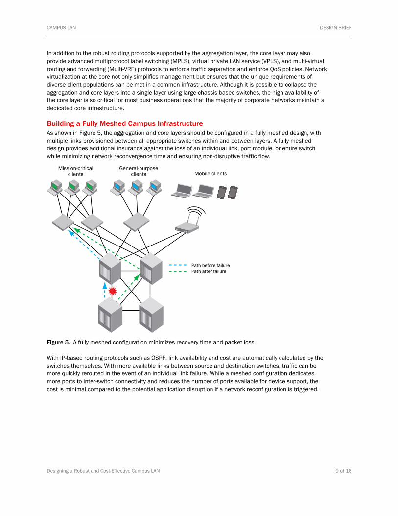
Building a Fully Meshed Campus Infrastructure As shown in Figure 5, the aggregation and core layers should be configured in a fully meshed design, with multiple links provisioned between all appropriate switches within and between layers. A fully meshed design provides additional insurance against the loss of an individual link, port module, or entire switch while minimizing network reconvergence time and ensuring non-disruptive traffic flow.
Mission-criticalclients
General-purposeclients Mobile clients
Path before failurePath after failure
e
erouted in the event of an individual link failure. While a meshed configuration dedicates more ports to inter-switch connectivity and reduces the number of ports available for device support, the
otential application disruption if a network reconfiguration is triggered.
Figure 5. A fully meshed configuration minimizes recovery time and packet loss.
With IP-based routing protocols such as OSPF, link availability and cost are automatically calculated by thswitches themselves. With more available links between source and destination switches, traffic can be more quickly r
cost is minimal compared to the p
Designing a Robust and Cost-Effective Campus LAN 9 of 16

CAMPUS LAN DESIGN BRIEF
BROCADE CAMPUS LAN SOLUTIONS Brocade® now offers a full suite of Layer 2 and Layer 3 IP network solutions, as well as advanced Layer 4/7 products for application offload. Brocade network infrastructure products are engineered for enterpriseclass applications and combine high performance with resiliency and industry-leading energy efficiency. Fcampus LAN deployments, Brocade offers a broad spectrum of access, wireless access, aggregation, and high-availability core switches to build a complete end-to-end solution for both large and medium enterprises.
-or
bps t
of client devices. Designed for high availability at the access layer, FastIron switches provide redundant hot-swappable power supplies. High-performance 10 GbE ports can be configured to provide uplinks to aggregation layer switches.
Brocade Wired Campus LAN Access Switches The Brocade FastIron series access switches are available in both stackable and chassis-based configurations and scale from 24 and 48 ports with 96 Gbps switching capacity to 192 ports with 510 Gswitching capacity. In both stackable and chassis formats, the FastIron series can be deployed to suppormodest port requirements and then scale over time to accommodate higher populations
To the aggregation layer To clients and PoE devices
Figure 6. The Brocade FastIron series provides high performance uplinks and PoE to VoIP phones, wireless access points, security cameras, and other devices.
As shown in Figure 6, the Brocade FastIron access switches provide high-performance connectivity to the aggregation layer and the flexibility to support 10/100/1000 MbE clients as well as PoE-enabled devices. By combining high port density with a compact rackable form factor, FastIron switches occupy minimal real estate in wiring closets and simplify deployment of both conventional and PoE end devices.
Brocade’s support for both IEEE 802.3af PoE and 802.3at PoE+ standards at the access layer provides both data and power connectivity for multiple classes of PoE-capable phone systems, wireless access
dard CAT-5 cabling. The integration of both data and PoE connectivity adds another step in the network design process to ensure
is
points, environmental sensors, security cameras, and other equipment using stan
that sufficient power is allocated to the appropriate end devices. Because Brocade offers FastIron switches in a variety of configurations and port densities, alignment of both data connectivity and PoE distribution facilitated, as shown in Figure 7.
Designing a Robust and Cost-Effective Campus LAN 10 of 16

CAMPUS LAN DESIGN BRIEF
Designing a Robust and Cost-Effective Campus LAN 11 of 16
BranchOffice
Enterpriseborder
Enterpriseborder
Connectionto data center
BackboneCampus
CampusDistribution
SmallCampus Access
MediumCampus Access
LargeCampus Access
FastIronCX Fastiron
SuperX
FastironWS FastIron
SX 1600
FastironEdge SX
IronViewNetworkManager
NAC
BigIronRX
Brocade prod- FastIron WS- NetIron MLX- Mobility controllers, acce- IronView Network Manag
BigIronRX
NetIronMLX
NetIronMLX
NetIronMLX
NetIronMLX
NetworkAdmission
ControlIP
Communi-cation ucts
, CX, EdgeX, SuperX
ss pointser
BrocadeMobility
Figure 7. Sizing access layer connectivity for both data and PoE requirements .
of Service delivery, and VLAN-based ACL policy
ns.
es several streams to be broadcast simultaneously.
The design criteria for legacy 802.11a/b/g and 802.11n networks have significant differences. Consequently, deploying an 802.11n system is not a simple matter of swapping legacy access points for new ones. Maximizing the performance and coverage of 802.11n technology on the campus may require some redesign of access point placement to ensure that both legacy and new 802.11n devices are adequately covered. To help customers navigate this process, Brocade offers services and tools to facilitate wireless technology migration when needed.
Brocade access points include the Brocade Mobility 300 and 5181 series for 802.11a/b/g device support and the Mobility 7131 series for 802.11a/b/g/n device support. Mobility access points can be centrally managed and secured through use of Mobility RFS6000 (medium enterprise) and RFS7000 (large
Brocade access layer switches support advanced Layer 2 and base Layer 3 protocols, including edge security, IEEE 802.1x port-based authentication, Qualityenforcement. These intelligent edge services provide secure connectivity for client workstations and edge devices and enable network designers to deploy QoS as needed for high-priority or latency-sensitive applications.
Brocade Wireless Campus LAN Access Points and Controllers The proliferation of IEEE 802.11 wireless technology has enabled much greater mobility for campus LAN clients and higher productivity, as users are no longer tethered to fixed Ethernet connectioLegacy IEEE 802.11a/b/g typically runs on a 2.4 GHZ frequency with maximum data rate of 54 Mbps. The new IEEE 802.11n standard is backward compatible with IEEE 802.11a/b/g devices but can run on a 5 GHZ frequency with at a maximum data rate of 600 Mbps for 802.11n devices. IEEE 802.11n achieves higher performance by using 40 MHZ channels and a multiple antennae (multiple input, multiple output (MIMO)) architecture, which enabl

CAMPUS LAN DESIGN BRIEF
enterprise) series controllers. The RFS6000 and RFS7000 enable advanced functionality for access points, including centralized and distributed traffic forwarding, plug-and-play access point deployment, IPSec-encrypted tunneling, enhanced management, access point load balancing, and Remote Site Survivability (RSS) to ensure continuous coverage in the event of failures.
Because 802.11n services are readily available within a zone of coverage, security is a paramount concern. Centralized security enforcement via Brocade RFS controllers can provide authenticated access and encryption of data streams that might otherwise be vulnerable to wireless snooping. In addition to corporate users, companies may wish to provide guest WLAN access to non-restricted resources such as the Internet. This is more easily managed on a centralized basis in which the RFS series controllers manage security policies.
As shown in Figure 8, Brocade WLAN products can be used to build extensive wireless infrastructures that span multiple buildings and sites. With support for up to 1024 access points per controller and up to 12,288 per cluster, Brocade access points and RFS series controllers can scale to the largest enterprise requirements. In addition, Brocade WLAN technology is designed to provide self-healing infrastructures in the event of a loss of signal strength or coverage.
HeadquartersAdjacent Building
Outdoor meshAP 5181
Designing a Robust and Cost-Effective Campus LAN 12 of 16
802.11a/b/g
Indoor meshAP 7131
802.11a/b/g/nIndoor meshAP 7131
802.11a
AP 300 AP 300 AP 300
/b/g/n
Small officesand store fronts
Mediumenterprise
AP 300AP 7131 AP 7131
Locations
RFS7000sRFS7000s
WANbackhaul
Wired connection Wireless connection Long-distance wired or wireless connection
Headquarters/NOC
CampusGrounds
accesslayer
Point-to-point/point-to-multipoint3G/4G broadband backhaul
RFS6000
Remote
AP 300
Figure 8. Building a comprehensive WLAN campus infrastructure with Brocade access points and controllers.

CAMPUS LAN DESIGN BRIEF
The combination of Brocade wired access layer switches and scalable WLAN solutions enables customers to provide the optimum network connectivity for users throughout the corporate campus. By supportingboth conventional IEEE 802.11a/b/g and new IEEE 802.11n standards, bandwidth allocation can be aligned to the performance requirements of different user grou
ps and application needs. And with Brocade FastIron support for PoE and PoE+, WLAN access points can be integrated into a streamlined network
. r
BigIron RX series provides a chassis-based high-availability platform to aggregate hundreds of access layer switches and devices. With connectivity for up to 128 x 10 Gbps Ethernet links or up to 1,536 Fast and Gigabit Ethernet links per chassis, the BigIron RX can be deployed throughout the campus to bring edge devices into the network core. Given the aggregation of potentially thousands of workflows, aggregation layer switches must provide high-performance backplanes capable of handling intense traffic patterns. The 5.12 Tbps switching capacity and more than 2 billion packets per second forwarding capacity of the BigIron provide the maximum throughput at Layer 3.
design that simplifies cabling and power distribution.
Brocade Campus Aggregation Layer Solutions Brocade campus LAN aggregation layer switches include the FastIron® SX and BigIron® RX series platforms. Both series incorporate modular designs that enable customers to align aggregation deployments to the appropriate port density and performance requirements of different campus areas. The FastIron SX series is available in 8 and 16 slot chassis with up to 400 x Gigabit Ethernet ports or up to 36 x 10 GbE portsThe FastIron SX also supports up to 384 PoE-enabled ports for aggregating wireless access points or othePoE devices.
For large campus LAN configurations, the Brocade
Figure 9. The Brocade BigIron RX and FastIron SX switch families scale from medium to large deployments.
As shown in Figure 9, the BigIron RX series can be deployed for a wide variety of aggregation layer requirements as needed for different campus LAN configurations. For smaller buildings, the RX-4 or RX-8 chassis may be sufficient, while centralized structures may require the RX-32 or RX-16 chassis. Typically, aggregation layer switches are deployed in a redundant configuration to provide alternate pathing. The BigIron chassis, however, also incorporates individual high availability features such as redundant management modules, redundant fabric modules, hot swappable power supplies, fan units, and port modules for the highest availability.
Because the aggregation layer typically requires more robust routing support, Brocade aggregation solutions provide full Layer 3 IPv4 and IPv6 routing, including RIPv1/v2, RIPng, OSPFv2/v3, IS-IS, BGP-4, DVMRP, and PIM-SM/DM as described above. With wire-speed performance and a rich suite of routing protocols, the
integrated FastIron SX and BigIron RX series switches can bring hundreds or thousands of devices into anand more easily managed campus LAN architecture.
Designing a Robust and Cost-Effective Campus LAN 13 of 16

CAMPUS LAN DESIGN BRIEF
Brocade Campus Core Layer Solutions While each aggregation layer switch provides reliable connectivity for discrete groups of access layer switches and access points, the core layer is responsible for the seamless operation of entire campus infrastructure, including connectivity to the data center and to external networks. So in addition to the high availability and high performance functionality characteristic of aggregation layer switches, core layer platforms must provide further enhancements to perfo
LAN
rmance, WAN connectivity options, and higher-level protocols for advanced services such as MPLS, VPLS, and virtual routing for network virtualization. These
pus LAN to more easily meet diverse upper-
and support for up to 128 x 10 GbE ports, the NetIron MLX is designed to
advanced features simplify management and enable the camlayer application requirements and business goals.
The Brocade NetIron® MLX series switches are designed for the more rigorous requirements of the campus LAN core and are available in modular chassis configurations to meet specific performance and connectivity needs. As illustrated in Figure 10, the NetIron MLX core switches provide from 4 to 32 slots for any combination of Gigabit Ethernet and 10 GbE and WAN port distribution. With up to 7.68 Terabits per second (Tbps) switching capacitycentralize campus LAN traffic management for continuous non-disruptive operation.
Figure 10. The Brocade NetIron MLX core layer switch series provides both aggregation layer and WAN connectivity.
Conventional WAN connectivity for external networks is provided through 4 and 8 port OC48 (2.5 Gbps) and 2 port OC192 (9.6 Gbps) modules. In addition, 10 GbE ports can be used to connect to Carrier Grade Ethernet networks for metropolitan environments. The NetIron MLX architecture is future proofed to support
multi-
emerging 40 GbE and 100 GbE standards, which will provide greater flexibility for both mesh inter-switch links and high-performance campus core backbones.
Advanced routing services at the core layer include MPLS and multi-virtual routing and forwarding (VRF), advanced QoS for multi-service networks and sFlow management for more granular network traffic accounting. These NetIron MLX capabilities enable the construction of highly reliable core infrastructures that facilitate transport of multiple traffic protocols over an integrated network.
Designing a Robust and Cost-Effective Campus LAN 14 of 16

CAMPUS LAN DESIGN BRIEF
Building and Managing a Brocade Campus LAN and Brocade’s standards-based IP technology provides a wide variety of solutions for access, aggregation,
core layer connectivity, all centrally managed via a secure and robust management framework, Brocade IronView® Network Manager (INM).
Mission-criticalclients
General-purposeclients Mobile clients
Fastiron
Designing a Robust and Cost-Effective Campus LAN 15 of 16
Aggregation
Core
Access Brocade Mobilityaccess point
NetIron MLX
BigIron/FastIron SX
External networks
ron wired access layer switches, Mobility wireless access points, BigIron and FastIron SX
enforcement is facilitated by access control list
Figure 11. Building a robust tiered campus LAN with Brocade IP technology.
Brocade FastIaggregation layer switches, and high-performance NetIron MLX core switches enable customers to selectively deploy the most efficient solutions that meet campus LAN requirements. As shown in Figure 11, these technologies can be configured for a wide range of client access requirements at the network edge and scale through the aggregation and core layers to meet bandwidth and availability needs. Link aggregation between aggregation layer switches and the network core can be dynamically sized to accommodate traffic changes over time. Security policyauthentication, data encryption, IPSec, and VLAN enforcement throughout the network.

CAMPUS LAN DESIGN BRIEF
Designing a Robust and Cost-Effective Campus LAN 16 of 16
Figure 12. Brocade IronView management provides comprehensive management of all aspects of the campus LAN.
As illustrated in Figure 12, Brocade IronView management provides a comprehensive view of the campus LAN environment and full control over device configuration and monitoring. This enables network administrators to maximize network performance while ensuring that essential corporate security and service-level agreement (SLA) policies are enforced.
SUMMARY pporting a wide range of client
le
, quirements.
© 2009 Brocade Communications Systems, Inc. All Rights Reserved. 12/09 GA-DG-240-00
Brocade, the B-wing symbol, BigIron, DCX, Fabric OS, FastIron, IronPoint, IronShield, IronView, IronWare, JetCore, NetIron, SecureIron, ServerIron, StorageX, and TurboIron are registered trademarks, and DCFM, Extraordinary Networks, and SAN Health are trademarks of Brocade Communications Systems, Inc., in the United States and/or in other countries. All other brands, products, or service names are or may be trademarks or service marks of, and are used to identify, products or services of their respective owners.
Notice: This document is for informational purposes only and does not set forth any warranty, expressed or implied, concerning any equipment, equipment feature, or service offered or to be offered by Brocade. Brocade reserves the right to make changes to this document at any time, without notice, and assumes no responsibility for its use. This informational document describes features that may not be currently available. Contact a Brocade sales office for information on feature and product availability. Export of technical data contained in this document may require an export license from the United States government.
Campus LANs have unique design criteria that demand greater flexibility in sudevices and applications. Wired access, wireless access, and Power over Ethernet devices must coexist at the network edge. Mission-critical client applications may require high bandwidth, high availability, and security while mid-tier applications may be adequately served with more modest connectivity. A tiered campus LAN architecture with fan-out to client devices at the access layer, consolidation of access layer traffic through the aggregation layer, and centralized routing through the network core provides a scalablemodel for growing the campus LAN over time and accommodating higher traffic volumes and multipprotocols as required. Brocade’s full suite of intelligent campus LAN IP infrastructure solutions and comprehensive network management tools enable customers to build and expand robust, cost-effectiveand business-optimized campus networks that meet both current and future corporate re