designing and implementing ipv6 mobility stack on bsd operating
TRANSCRIPT
1
特集●
Designing and Implementing IPv6 Mobility
stack on BSD Operating Systems
Keiichi Shima Koshiro Mitsuya Tsuyoshi Momose Shuichi Karino
Ryuji Wakikawa Kazushi Sugyou Keisuke UeharaMobile IPv6 and NEMO BS are IETF standard mobility protocols for IPv6. It is said that freely available
implementations play a big role in the deployment of new protocols. To accelerate the deployment of IPv6
mobility, we implemented the different mobility protocol stacks for the BSD operating systems. During
the development, we made two different implementations based on this different design policies. The first
one was an in-kernel implementation and the other a user space implementation. The former design makes
it easy to use kernel information necessary for mobility operation, but it is difficult to implement and to
extend features than the latter. The latter design needs to have extra mechanisms to retrieve or inject kernel
information from user space, but in most cases developing user space programs is easier than developing in
the kernel. In this paper, we discuss the design policies and implementation details of these two stacks.
1 Introduction
The rapid growth of the IPv4 Internet raised con-
cerns of the exhaustion of the IPv4 address space.
IPv6 was designed as the essential solution to this
problem. We are now in the transition period from
an IPv4 Internet to an IPv6 Internet. As a result
of the transition, a vast number of IPv6 devices
connected to the Internet using various communi-
cation technologies will appear in the future. The
devices will not only be computers and PDAs but
also cars, mobile phones, sensor devices and so on.
Since many devices will potentially move around
changing their point of attachment to the Internet,
mobility support for IPv6 is considered necessary.
The IETF has discussed the protocol specification
and finally standardized two IPv6 mobility proto-
cols, Mobile IPv6 [7] for host mobility and Network
Mobility Basic Support (NEMO BS) [2] for network
BSD オペレーティングシステム用 IPv6 モビリティプロトコルスタックの設計と実装島慶一, 株式会社インターネットイニシアティブ, Internet
Initiative Japan Inc.
百瀬 剛, 狩野 秀一, 須堯 一志, 日本電気株式会社, NEC
Corporation
三屋 光史朗, 湧川 隆次, 植原 啓介, 慶應義塾大学, Keio
University
mobility.
When deploying a new protocol, it is often ef-
ficient to provide the protocol stack as an open
source software. The developers of the protocol
stack can get feedback from users worldwide and
can thereby enhance their implementation. For ex-
ample, the IPv6 protocol stack developed by the
KAME project [24] accelerated the implementation
of IPv6 in various operating systems. We intended
to do the same thing for the mobility protocols. We
implemented the IPv6 mobility stacks: the KAME
Mobile IPv6 stack and the SHISA [25] [17] mobility
stack. In this paper, we will discuss the design and
implementation details of these two models.
2 Overview of Mobile IPv6 and
NEMO BS
Mobile IPv6 is a protocol which adds a mobility
function to IPv6. In Mobile IPv6, a moving node
(Mobile Node, MN ) has a Home Address (HoA)
which is its permanently fixed address. The HoA
is assigned to the MN by the network to which the
MN is originally attached. This network is called
the Home Network, all other networks are referred
as Foreign Networks. When the MN moves to other
networks, the MN sends a message to bind its HoA
and the address assigned at the foreign network,
2 コンピュータソフトウェア
Mobile Node (MN)Home Agent (HA)
Home Network Foreign Network
Move
Care-of Address (CoA)Home Address (HoA)
Internet
Correspondent Node (CN)
CommunicationMN - CN
Bi-directional Tunnel
Binding Update(HoA - CoA)
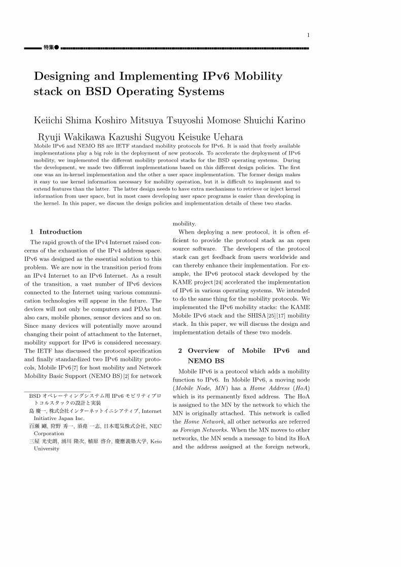
Fig. 1 Basic Operation of Mobile IPv6.
Care-of Address (CoA). The message is called a
Binding Update (BU ) message. This message is
sent to a special node, the Home Agent (HA), which
is located in the home network. The HA replies
to the MN with a Binding Acknowledgement (BA)
message to confirm the request. A bi-directional
tunnel between the HA and the CoA of the MN is
established after the binding information has been
successfully exchanged. All packets sent to the
HoA of the MN are routed to the home network
by the standard Internet routing mechanism. The
HA intercepts the packets and forwards them to the
MN using the tunnel. The MN also sends packets
using the tunnel when communicating with other
nodes. The communicating nodes, Correspondent
Nodes (CN ), do not need to know the actual lo-
cation of the MN, since they communicate to the
MN through its home network attachment. Fig. 1
illustrates the operation of Mobile IPv6.
In Fig. 1, the communication path between the
MN and its peer node is redundant since all traffic
is forwarded via the HA. Mobile IPv6 provides an
optimized way to communicate with an IPv6 node
which is aware of the Mobile IPv6 protocol. An
MN can send a BU message to a CN. When send-
ing the BU message, the MN must perform a simple
address ownership verification procedure, the Re-
turn Routability (RR) procedure. The MN sends
two messages, Home Test Init (HoTI ) and Care-of
Test Init (CoTI ) messages, to the CN, one from its
HoA and the other from its CoA. The CN replies
to these two messages by generating two separate
cookies and send them in a Home Test (HoT ) and
Home Agent (HA)
Home Network Foreign Network
Move
Internet
Correspondent Node (CN)
CommunicationMNN - CN
Bi-directional Tunnel
Home Address
Mobile Network Mobile Network
Care-of Address
Binding Update(HoA - CoA,Mobile Network Prefix)
Mobile Network Nodes (MNNs)
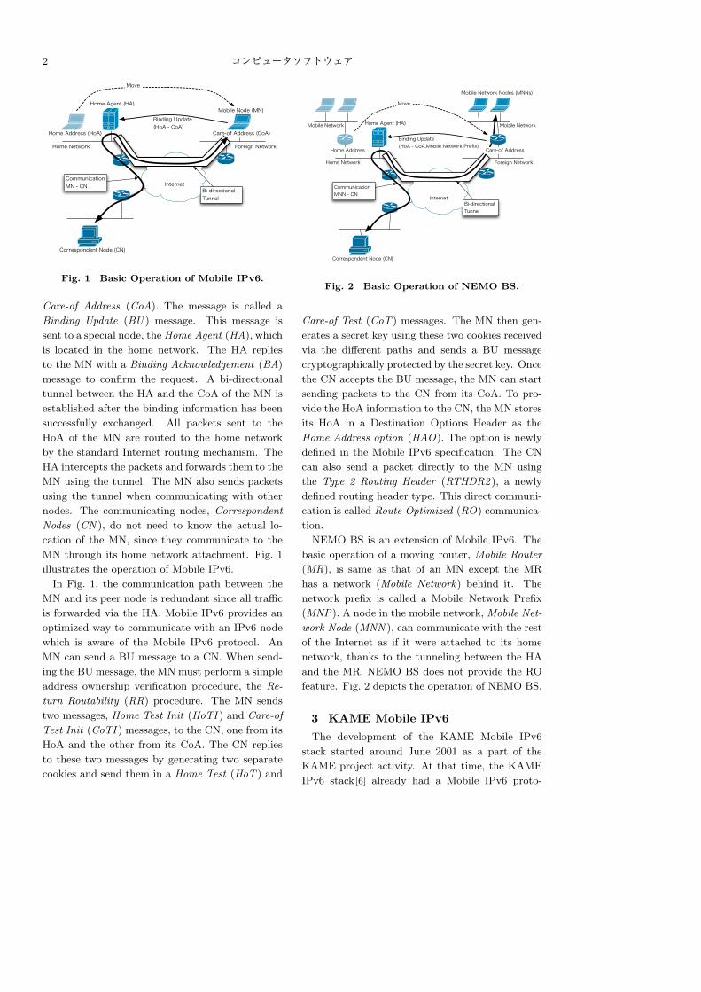
Fig. 2 Basic Operation of NEMO BS.
Care-of Test (CoT ) messages. The MN then gen-
erates a secret key using these two cookies received
via the different paths and sends a BU message
cryptographically protected by the secret key. Once
the CN accepts the BU message, the MN can start
sending packets to the CN from its CoA. To pro-
vide the HoA information to the CN, the MN stores
its HoA in a Destination Options Header as the
Home Address option (HAO). The option is newly
defined in the Mobile IPv6 specification. The CN
can also send a packet directly to the MN using
the Type 2 Routing Header (RTHDR2 ), a newly
defined routing header type. This direct communi-
cation is called Route Optimized (RO) communica-
tion.
NEMO BS is an extension of Mobile IPv6. The
basic operation of a moving router, Mobile Router
(MR), is same as that of an MN except the MR
has a network (Mobile Network) behind it. The
network prefix is called a Mobile Network Prefix
(MNP). A node in the mobile network, Mobile Net-
work Node (MNN ), can communicate with the rest
of the Internet as if it were attached to its home
network, thanks to the tunneling between the HA
and the MR. NEMO BS does not provide the RO
feature. Fig. 2 depicts the operation of NEMO BS.
3 KAME Mobile IPv6
The development of the KAME Mobile IPv6
stack started around June 2001 as a part of the
KAME project activity. At that time, the KAME
IPv6 stack [6] already had a Mobile IPv6 proto-
Vol. 0 No. 0 1983 3
Table1 ICMPv6 messages handling.
ICMPv6 message type Sent from Processed by
Dynamic Home Agent
Address Discovery Re-
quest
kernel user space
Dynamic Home Agent
Address Discovery Re-
ply
user space kernel
Mobile Prefix Solicita-
tion
kernel user space
Mobile Prefix Adver-
tisement
user space kernel
Router Advertisement user space kernel
col stack contributed by Ericsson, however no one
in the KAME project was maintaining the con-
tributed code. To keep the code up-to-date to the
specification and keep enhancing the quality of the
code, we decided to have our own Mobile IPv6 stack
on top of the KAME IPv6 stack. This code was de-
veloped and maintained until April 2004 when we
started the development of the new mobility code
discussed in Section 4.
3. 1 KAME Mobile IPv6 Design
When designing the KAME Mobile IPv6, we de-
fined the goals of the stack as follows:
• Providing a simple configuration architecture
to use Mobile IPv6.
• Node type based coding to reduce the object
size.
The KAME Mobile IPv6 was designed as a part
of the kernel, whose design is the same as Erics-
son’s code used before the KAME Mobile IPv6. All
types of the Mobility Header, newly defined IPv6
extension header for carrying mobility related sig-
naling messages, are processed in the kernel. The
exceptions was the handling of a few ICMPv6 mes-
sages extended in RFC 3775. In the KAME IPv6
protocol design, the ICMPv6 messages are handled
both in the kernel space and user space (e.g. the
ICMPv6 Echo Request message is sent from the
ping6 program, user space, and the ICMPv6 Echo
Reply message is handled in the kernel). The Raw
socket mechanism provides the user space programs
access to ICMPv6 messages. We utilized this mech-
anism to reduce kernel code size. Table 1 shows the
ICMPv6 messages related to Mobile IPv6 that are
handled in user space.
The reason we implemented the stack in the ker-
nel was that the specification of the Mobile IPv6,
when we started implementing it, was using the
Destination Options Header for mobility signaling
messages. The Destination Options Header is one
of the IPv6 extension headers and the basic pro-
cessing code had already been implemented in the
kernel as a part of the KAME IPv6 stack. Imple-
menting the Mobile IPv6 stack in the kernel extend-
ing the Destination Options Header processing code
was natural choice at that time. The IETF Mo-
bile IP Working Group later changed the message
container from the Destination Options Header to
the Mobility Header which can be handled in user
space. We could have switched the stack from a ker-
nel implementation to a user space implementation,
however this change was delayed until we started
designing the SHISA stack. Since the change would
have required an entire stack re-designing, possibly
causing quality problems, we continued the kernel
implementation to keep the code stable.
The main problem with implementing all func-
tions in the kernel is that it increases kernel size.
In fact, since most users are not going to use the
mobility function, providing it in the kernel is a
waste of the code space for these users. This code
bloat can be somewhat addressed by the decision
to have the KAME Mobile IPv6 code designed as
a supplemental function to the existing IPv6 code
and our goal to not modify the existing kernel code
as much as possible. The code is also divided into
several parts based on the type of the node defined
in the Mobile IPv6 specification (MN, CN and HA)
and users of the stack can easily drop unnecessary
code, based on their usage requirements. This de-
sign will help to reduce the total size of the code,
when code size is considered a important problem,
e.g. for embedded platforms.
3. 2 KAME Mobile IPv6 Implementation
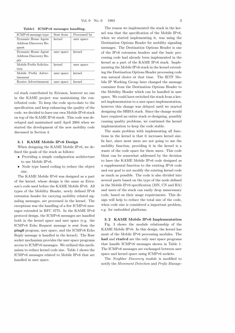
Fig. 3 shows the module relationship of the
KAME Mobile IPv6. In this design, the kernel has
most of the Mobile IPv6 processing modules. The
had and rtadvd are the only user space programs
that handle ICMPv6 messages shown in Table 1.
The ICMPv6 messages are exchanged between user
space and kernel space using ICMPv6 sockets.
The Neighbor Discovery module is modified to
notify the Movement Detection and Prefix Manage-
4 コンピュータソフトウェア
had rtadvd
user
space
kernel
space
ICMPv6 Socket
Binding Management
Module
Neighbor Discovery Module
Forwarding Module
Binding Update
Database
Binding Cache
Database
Address Management
Module
Return Routability Module
ICMPv6 Module
Movement Detection Module
Destination Options Header
Module
Routing Header Module
Tunneling Module
Prefix Management
Module
Routing Table
Fig. 3 The module layout of the KAME Mobile IPv6. The dotted boxes are modules that exist in
the base KAME IPv6 protocol stack. The shaded boxes are modules that did not require any
modification to support Mobile IPv6. The boxes with solid lines are newly introduced modules for
Mobile IPv6.
ment modules of received prefix information. The
Movement Detection module detects MN’s move-
ment by the current prefix information and its cur-
rently assigned address status. The Prefix Manage-
ment module keeps prefix information for the MN’s
home network and foreign networks. The Address
Management module is extended to support HoAs,
the permanent addresses used by an MN.
The Return Routability module processes signal-
ing messages for the RO communication and puts
binding information into the Binding Management
module. The Binding Management module keeps
the binding information between the HoA and CoA
of the MN. The module manages a Binding Update
List database (in an MN) and/or a Binding Cache
database (in an HA/CN). The Forwarding module
and the Tunneling module look up these databases
when sending or receiving packets, and process ev-
ery packets based on the binding information.
The Destination Options Header module pro-
cesses the HAO options of the incoming packets. If
the HoA included in the incoming HAO is invalid,
the packet must be dropped. The Routing Header
module processes the Type 2 Routing Header intro-
duced by Mobile IPv6.
Vol. 0 No. 0 1983 5
3. 3 KAME Mobile IPv6 Problems
We found several problems in the KAME Mobile
IPv6 stack. The first problem is its extensibility.
Since almost all of the code is implemented as ker-
nel functions, they highly depend on the internal
design of the kernel, this makes it hard to extend
some specific parts of the module.
The second problem is the number of third party
developers. The number of the kernel developers
is relatively smaller than that of user space appli-
cation developers. As a result, the total amount
of feedback of the code might be smaller than it
should be.
Third, because the code is tightly integrated to
the kernel, it is difficult to replace some parts of the
mobility function. For example, movement detec-
tion may require code to handle specific events of
the environment of the operation scenarios of mo-
bile service carriers. However, if we want to do
it with KAME Mobile IPv6 implementation, we
would need to modify the kernel code related to
movement detection code.
Lastly, the fact that the KAME Mobile IPv6
needed large modification in the kernel is also a
problem when we consider integration of the code
into the original BSD distributions. For example,
we implemented the RR procedure in the kernel.
The RR procedure requires several messages be
exchanged and timeout/retry management. This
introduces complex state management and timer
handling on a per message basis in the kernel, which
should be avoided as much as possible. For these
reasons, we decided to redesign the entire stack
from scratch.
4 SHISA
The development of the SHISA mobility stack
started in April 2004 to overcome the problems
found in the KAME Mobile IPv6 stack. The latest
SHISA stack supports NEMO BS, Multiple Care-
of Address Registration [23] and Dual Stack support
[12] [19] in addition to Mobile IPv6.
4. 1 SHISA Design
SHISA is designed to achieve the following goals.
• Separation of signaling processing layer and
forwarding processing layer:
The operation of Mobile IPv6 and NEMO BS
is basically IP packet routing (forwarding or
tunneling). To get better performance, packet
processing of normal traffic should be done in
kernel space, while the signal processing should
be done in user space, since the signal process-
ing is complex and it is easier to modify/update
user space programs than the kernel. This sep-
aration will give the stack both good perfor-
mance and increased efficiency in stack devel-
opment.
• Adaptability to various movement scenarios:
The mechanism required for movement detec-
tion and performance varies based on the de-
mands of operators. The signaling mechanism
and movement detection mechanism must be
independent, because the signaling procedure
usually never changes unless the protocol spec-
ification changes. Movement detection code
must be replaceable in response to operator’s
requirements.
• Extensibility:
IPv6 mobility technologies are one of most ac-
tive area in Internet research. The design of
the stack must provide an easy framework to
support several future functions yet undefined.
• Minimum modification on existing kernel
functions:
We believe the mobility function will be a core
function in future operating systems. To inte-
grate the implementation to the target oper-
ating system (in our case, the BSD operating
systems), we have to minimize the modification
for existing kernel functions.
In the following sections, we will discuss the im-
plementation decisions we have made based on the
above requirements.
4. 2 SHISA Implementation
SHISA is implemented on top of the KAME IPv6
stack [6]. The fact that the KAME IPv6 stack cov-
ered most of the IPv6 functions and API functions
made it easier for us to implement the mobility
stack on it. What we had to implement was the
mobility related functions only, and there was no
need to implement other IPv6 core functions.
4. 3 Supported Features
Our SHISA implementation provides the follow-
ing functions:
• Mobile IPv6 functions for MN, HA and CN
6 コンピュータソフトウェア
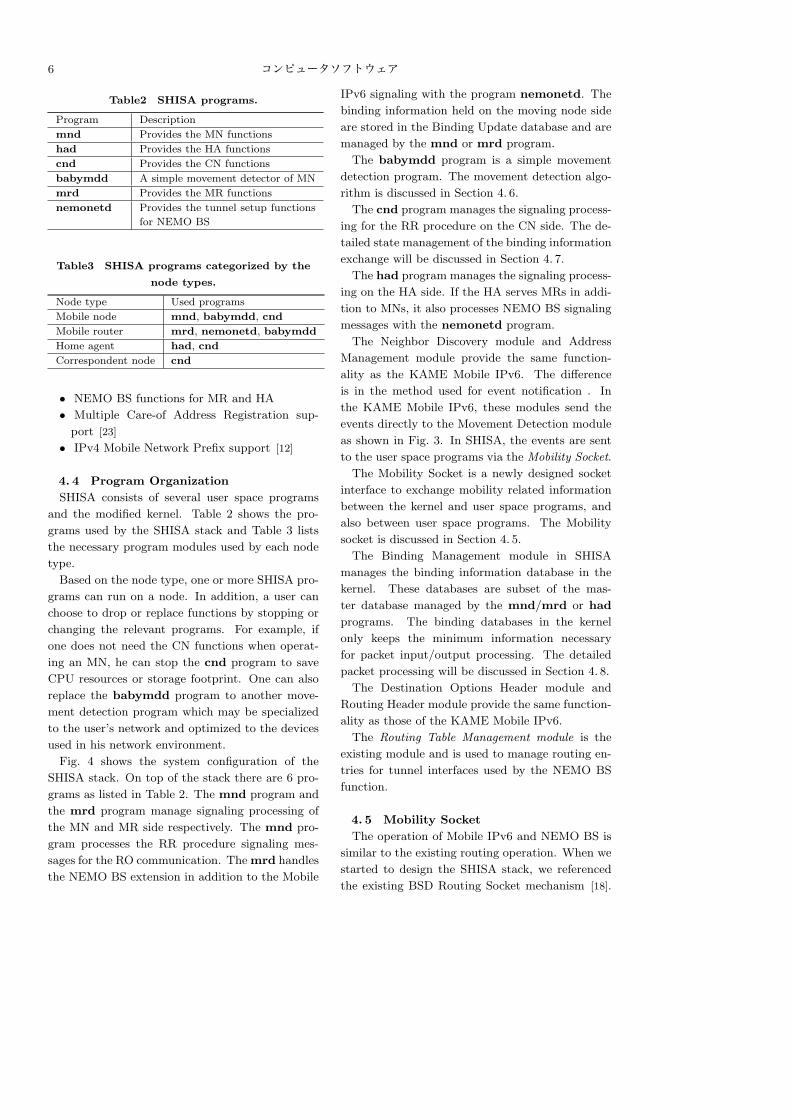
Table2 SHISA programs.
Program Description
mnd Provides the MN functions
had Provides the HA functions
cnd Provides the CN functions
babymdd A simple movement detector of MN
mrd Provides the MR functions
nemonetd Provides the tunnel setup functions
for NEMO BS
Table3 SHISA programs categorized by the
node types.
Node type Used programs
Mobile node mnd, babymdd, cnd
Mobile router mrd, nemonetd, babymdd
Home agent had, cnd
Correspondent node cnd
• NEMO BS functions for MR and HA
• Multiple Care-of Address Registration sup-
port [23]
• IPv4 Mobile Network Prefix support [12]
4. 4 Program Organization
SHISA consists of several user space programs
and the modified kernel. Table 2 shows the pro-
grams used by the SHISA stack and Table 3 lists
the necessary program modules used by each node
type.
Based on the node type, one or more SHISA pro-
grams can run on a node. In addition, a user can
choose to drop or replace functions by stopping or
changing the relevant programs. For example, if
one does not need the CN functions when operat-
ing an MN, he can stop the cnd program to save
CPU resources or storage footprint. One can also
replace the babymdd program to another move-
ment detection program which may be specialized
to the user’s network and optimized to the devices
used in his network environment.
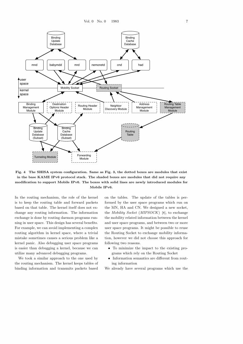
Fig. 4 shows the system configuration of the
SHISA stack. On top of the stack there are 6 pro-
grams as listed in Table 2. The mnd program and
the mrd program manage signaling processing of
the MN and MR side respectively. The mnd pro-
gram processes the RR procedure signaling mes-
sages for the RO communication. The mrd handles
the NEMO BS extension in addition to the Mobile
IPv6 signaling with the program nemonetd. The
binding information held on the moving node side
are stored in the Binding Update database and are
managed by the mnd or mrd program.
The babymdd program is a simple movement
detection program. The movement detection algo-
rithm is discussed in Section 4. 6.
The cnd program manages the signaling process-
ing for the RR procedure on the CN side. The de-
tailed state management of the binding information
exchange will be discussed in Section 4. 7.
The had program manages the signaling process-
ing on the HA side. If the HA serves MRs in addi-
tion to MNs, it also processes NEMO BS signaling
messages with the nemonetd program.
The Neighbor Discovery module and Address
Management module provide the same function-
ality as the KAME Mobile IPv6. The difference
is in the method used for event notification . In
the KAME Mobile IPv6, these modules send the
events directly to the Movement Detection module
as shown in Fig. 3. In SHISA, the events are sent
to the user space programs via the Mobility Socket.
The Mobility Socket is a newly designed socket
interface to exchange mobility related information
between the kernel and user space programs, and
also between user space programs. The Mobility
socket is discussed in Section 4. 5.
The Binding Management module in SHISA
manages the binding information database in the
kernel. These databases are subset of the mas-
ter database managed by the mnd/mrd or had
programs. The binding databases in the kernel
only keeps the minimum information necessary
for packet input/output processing. The detailed
packet processing will be discussed in Section 4. 8.
The Destination Options Header module and
Routing Header module provide the same function-
ality as those of the KAME Mobile IPv6.
The Routing Table Management module is the
existing module and is used to manage routing en-
tries for tunnel interfaces used by the NEMO BS
function.
4. 5 Mobility Socket
The operation of Mobile IPv6 and NEMO BS is
similar to the existing routing operation. When we
started to design the SHISA stack, we referenced
the existing BSD Routing Socket mechanism [18].
Vol. 0 No. 0 1983 7
babymddmnd hadnemonetdmrd cnd
Binding Management
Module
Mobility Socket Routing Socket
Address Management
Module
Neighbor Discovery Module
Forwarding Module
Binding Update
Database(Subset)
Binding Cache
Database(Subset)
Routing Table Management
Module
Routing Table
user
space
kernel
space
Binding Update
Database
Binding Cache
Database
Destination Options Header
Module
Routing Header Module
Tunneling Module
Fig. 4 The SHISA system configuration. Same as Fig. 3, the dotted boxes are modules that exist
in the base KAME IPv6 protocol stack. The shaded boxes are modules that did not require any
modification to support Mobile IPv6. The boxes with solid lines are newly introduced modules for
Mobile IPv6.
In the routing mechanism, the role of the kernel
is to keep the routing table and forward packets
based on that table. The kernel itself does not ex-
change any routing information. The information
exchange is done by routing daemon programs run-
ning in user space. This design has several benefits.
For example, we can avoid implementing a complex
routing algorithm in kernel space, where a trivial
mistake sometimes causes a serious problem like a
kernel panic. Also debugging user space programs
is easier than debugging a kernel, because we can
utilize many advanced debugging programs.
We took a similar approach to the one used by
the routing mechanism. The kernel keeps tables of
binding information and transmits packets based
on the tables. The update of the tables is per-
formed by the user space programs which run on
the MN, HA and CN. We designed a new socket,
the Mobility Socket (MIPSOCK ) [8], to exchange
the mobility related information between the kernel
and user space programs, and between two or more
user space programs. It might be possible to reuse
the Routing Socket to exchange mobility informa-
tion, however we did not choose this approach for
following two reasons.
• To minimize the impact to the existing pro-
grams which rely on the Routing Socket
• Information semantics are different from rout-
ing information
We already have several programs which use the
8 コンピュータソフトウェア
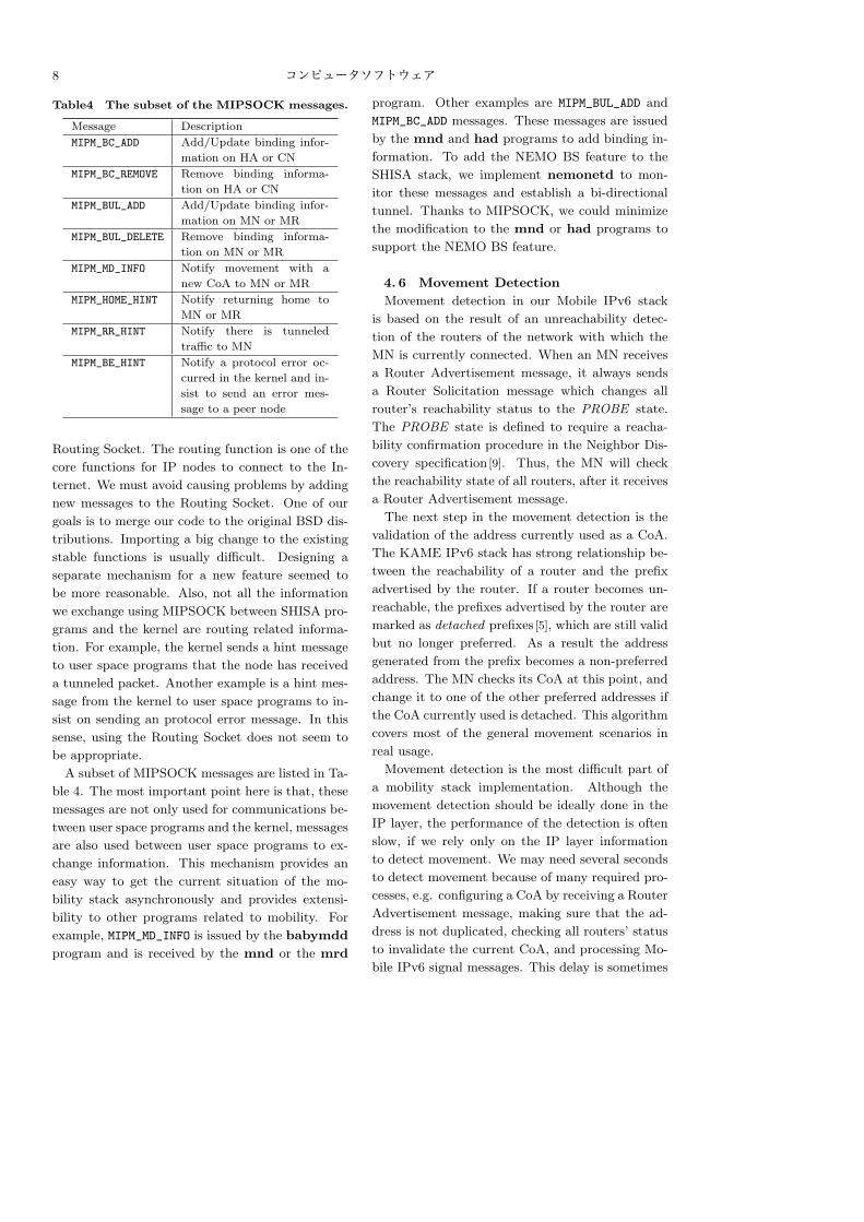
Table4 The subset of the MIPSOCK messages.
Message Description
MIPM_BC_ADD Add/Update binding infor-
mation on HA or CN
MIPM_BC_REMOVE Remove binding informa-
tion on HA or CN
MIPM_BUL_ADD Add/Update binding infor-
mation on MN or MR
MIPM_BUL_DELETE Remove binding informa-
tion on MN or MR
MIPM_MD_INFO Notify movement with a
new CoA to MN or MR
MIPM_HOME_HINT Notify returning home to
MN or MR
MIPM_RR_HINT Notify there is tunneled
traffic to MN
MIPM_BE_HINT Notify a protocol error oc-
curred in the kernel and in-
sist to send an error mes-
sage to a peer node
Routing Socket. The routing function is one of the
core functions for IP nodes to connect to the In-
ternet. We must avoid causing problems by adding
new messages to the Routing Socket. One of our
goals is to merge our code to the original BSD dis-
tributions. Importing a big change to the existing
stable functions is usually difficult. Designing a
separate mechanism for a new feature seemed to
be more reasonable. Also, not all the information
we exchange using MIPSOCK between SHISA pro-
grams and the kernel are routing related informa-
tion. For example, the kernel sends a hint message
to user space programs that the node has received
a tunneled packet. Another example is a hint mes-
sage from the kernel to user space programs to in-
sist on sending an protocol error message. In this
sense, using the Routing Socket does not seem to
be appropriate.
A subset of MIPSOCK messages are listed in Ta-
ble 4. The most important point here is that, these
messages are not only used for communications be-
tween user space programs and the kernel, messages
are also used between user space programs to ex-
change information. This mechanism provides an
easy way to get the current situation of the mo-
bility stack asynchronously and provides extensi-
bility to other programs related to mobility. For
example, MIPM_MD_INFO is issued by the babymdd
program and is received by the mnd or the mrd
program. Other examples are MIPM_BUL_ADD and
MIPM_BC_ADD messages. These messages are issued
by the mnd and had programs to add binding in-
formation. To add the NEMO BS feature to the
SHISA stack, we implement nemonetd to mon-
itor these messages and establish a bi-directional
tunnel. Thanks to MIPSOCK, we could minimize
the modification to the mnd or had programs to
support the NEMO BS feature.
4. 6 Movement Detection
Movement detection in our Mobile IPv6 stack
is based on the result of an unreachability detec-
tion of the routers of the network with which the
MN is currently connected. When an MN receives
a Router Advertisement message, it always sends
a Router Solicitation message which changes all
router’s reachability status to the PROBE state.
The PROBE state is defined to require a reacha-
bility confirmation procedure in the Neighbor Dis-
covery specification [9]. Thus, the MN will check
the reachability state of all routers, after it receives
a Router Advertisement message.
The next step in the movement detection is the
validation of the address currently used as a CoA.
The KAME IPv6 stack has strong relationship be-
tween the reachability of a router and the prefix
advertised by the router. If a router becomes un-
reachable, the prefixes advertised by the router are
marked as detached prefixes [5], which are still valid
but no longer preferred. As a result the address
generated from the prefix becomes a non-preferred
address. The MN checks its CoA at this point, and
change it to one of the other preferred addresses if
the CoA currently used is detached. This algorithm
covers most of the general movement scenarios in
real usage.
Movement detection is the most difficult part of
a mobility stack implementation. Although the
movement detection should be ideally done in the
IP layer, the performance of the detection is often
slow, if we rely only on the IP layer information
to detect movement. We may need several seconds
to detect movement because of many required pro-
cesses, e.g. configuring a CoA by receiving a Router
Advertisement message, making sure that the ad-
dress is not duplicated, checking all routers’ status
to invalidate the current CoA, and processing Mo-
bile IPv6 signal messages. This delay is sometimes
Vol. 0 No. 0 1983 9
IDLE
RRDEL
RRINIT
BOUND
WAITA
WAITD
WAITAR
RRREDO
RR_DONE:(Send a BU message)
RETURNING_HOME:(START_HOME_RR)
MOVEMENT:(START_RR)
MOVEMENT:REVERSE_PACKET:
(START_RR)
RR_DONE:(Send a BU message)
BA:
RETURNING_HOME:(Send a BU message)
BA:
TIMEOUT:(Send a BU message)
TIMEOUT:(Send a BU message)
BA:
MOVEMENT:(Send a BU message)
TIMEOUT:(Send a BU message)
TIMEOUT:(Send a BU message)
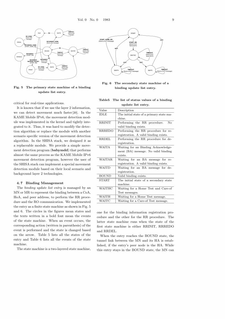
Fig. 5 The primary state machine of a binding
update list entry.
critical for real-time applications.
It is known that if we use the layer 2 information,
we can detect movement much faster [20]. In the
KAME Mobile IPv6, the movement detection mod-
ule was implemented in the kernel and tightly inte-
grated to it. Thus, it was hard to modify the detec-
tion algorithm or replace the module with another
scenario specific version of the movement detection
algorithm. In the SHISA stack, we designed it as
a replaceable module. We provide a simple move-
ment detection program (babymdd) that performs
almost the same process as the KAME Mobile IPv6
movement detection program, however the user of
the SHISA stack can implement a special movement
detection module based on their local scenario and
background layer 2 technologies.
4. 7 Binding Management
The binding update list entry is managed by an
MN or MR to represent the binding between a CoA,
HoA, and peer address, to perform the RR proce-
dure and the RO communication. We implemented
the entry as a finite state machine as shown in Fig. 5
and 6. The circles in the figures mean states and
the texts written in a bold font mean the events
of the state machine. When an event occurs, the
corresponding action (written in parenthesis) of the
event is performed and the state is changed based
on the arrow. Table 5 lists all the states of the
entry and Table 6 lists all the events of the state
machine.
The state machine is a two-layered state machine,
START
WAITHC
WAITCWAITH
START_RR:(Send CoTI, Send HoTI)
COT: HOT:
HOT:
START_HOME_RR:(Send a HoTI message)
TIMEOUT:(Send CoTI, Send HoTI)
TIMEOUT:(Send a CoTI message)
TIMEOUT:(Send a HoTI message)
COT:
Fig. 6 The secondary state machine of a
binding update list entry.
Table5 The list of status values of a binding
update list entry.
Value Description
IDLE The initial state of a primary state ma-
chine.
RRINIT Performing the RR procedure. No
valid binding exists.
RRREDO Performing the RR procedure for re-
registration. A valid binding exists.
RRDEL Performing the RR procedure for de-
registration.
WAITA Waiting for an Binding Acknowledge-
ment (BA) message. No valid binding
exists.
WAITAR Waiting for an BA message for re-
registration. A valid binding exists.
WAITD Waiting for an BA message for de-
registration.
BOUND Valid binding exists.
START The initial state of a secondary state
machine.
WAITHC Waiting for a Home Test and Care-of
Test messages.
WAITH Waiting for a Home Test message.
WAITC Waiting for a Care-of Test message.
one for the binding information registration pro-
cedure and the other for the RR procedure. The
latter state machine runs when the state of the
first state machine is either RRINIT, RRREDO
and RRDEL.
When the entry reaches the BOUND state, the
tunnel link between the MN and its HA is estab-
lished, if the entry’s peer node is the HA. While
this entry stays in the BOUND state, the MN can
10 コンピュータソフトウェア
Table6 The list of events of a binding update
list entry.
Name Description
MOVEMENT Moved to other foreign net-
work.
RETURNING HOME Returned to home.
REVERSE PACKET Received a bi-directional
packet.
RR DONE The return routability pro-
cedure has been completed.
BA Received a BA message.
TIMEOUT A retransmission timer ex-
pired.
START RR The RR procedure is initi-
ated.
START HOME RR The RR procedure for re-
turning home is initiated.
STOP RR The RR procedure is aborted.
HOT Received a Home Test mes-
sage.
COT Received a Care-of Test
message.
Table7 The list of status values of a binding
cache entry.
Value Description
BOUND Valid binding exists.
WAITB Waiting for an BA message for de-
registration.
WAITB2 Waiting for an BA message for de-
registration.
send or receive packets addressed to its HoA using
the tunnel link as explained in Section 2. If the
entry’s peer node is a CN, then the state means
the MN can perform RO communication with the
CN. The detailed packet processing is discussed in
Section 4. 8.
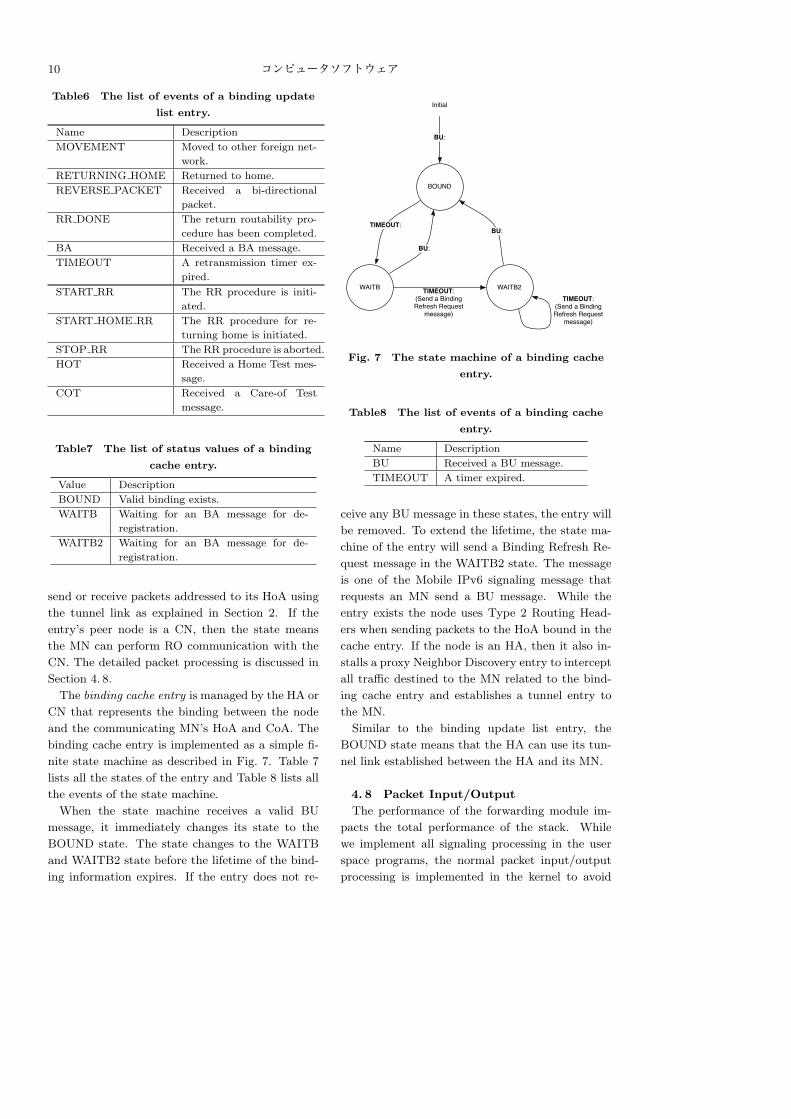
The binding cache entry is managed by the HA or
CN that represents the binding between the node
and the communicating MN’s HoA and CoA. The
binding cache entry is implemented as a simple fi-
nite state machine as described in Fig. 7. Table 7
lists all the states of the entry and Table 8 lists all
the events of the state machine.
When the state machine receives a valid BU
message, it immediately changes its state to the
BOUND state. The state changes to the WAITB
and WAITB2 state before the lifetime of the bind-
ing information expires. If the entry does not re-
BOUND
Initial
WAITB WAITB2
TIMEOUT:
BU:
BU:
TIMEOUT:(Send a BindingRefresh Request
message)
TIMEOUT:(Send a BindingRefresh Request
message)
BU:
Fig. 7 The state machine of a binding cache
entry.
Table8 The list of events of a binding cache
entry.
Name Description
BU Received a BU message.
TIMEOUT A timer expired.
ceive any BU message in these states, the entry will
be removed. To extend the lifetime, the state ma-
chine of the entry will send a Binding Refresh Re-
quest message in the WAITB2 state. The message
is one of the Mobile IPv6 signaling message that
requests an MN send a BU message. While the
entry exists the node uses Type 2 Routing Head-
ers when sending packets to the HoA bound in the
cache entry. If the node is an HA, then it also in-
stalls a proxy Neighbor Discovery entry to intercept
all traffic destined to the MN related to the bind-
ing cache entry and establishes a tunnel entry to
the MN.
Similar to the binding update list entry, the
BOUND state means that the HA can use its tun-
nel link established between the HA and its MN.
4. 8 Packet Input/Output
The performance of the forwarding module im-
pacts the total performance of the stack. While
we implement all signaling processing in the user
space programs, the normal packet input/output
processing is implemented in the kernel to avoid
Vol. 0 No. 0 1983 11
ip6_output()
Datalink layer input
Application socket output
nd6_output()
ip6_input()
ip6_forward()
nemo_output()
Datalink layer output
Binding Update DB lookup
mip6_output()
Binding Update DB lookup
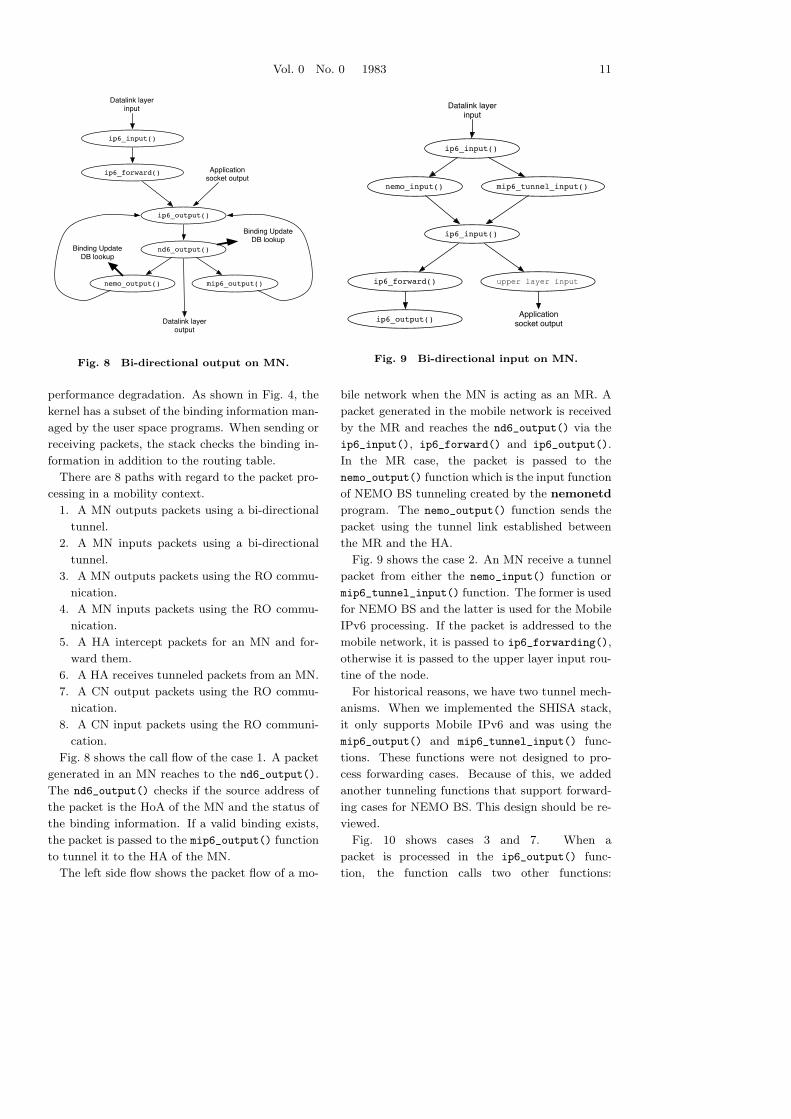
Fig. 8 Bi-directional output on MN.
performance degradation. As shown in Fig. 4, the
kernel has a subset of the binding information man-
aged by the user space programs. When sending or
receiving packets, the stack checks the binding in-
formation in addition to the routing table.
There are 8 paths with regard to the packet pro-
cessing in a mobility context.
1. A MN outputs packets using a bi-directional
tunnel.
2. A MN inputs packets using a bi-directional
tunnel.
3. A MN outputs packets using the RO commu-
nication.
4. A MN inputs packets using the RO commu-
nication.
5. A HA intercept packets for an MN and for-
ward them.
6. A HA receives tunneled packets from an MN.
7. A CN output packets using the RO commu-
nication.
8. A CN input packets using the RO communi-
cation.
Fig. 8 shows the call flow of the case 1. A packet
generated in an MN reaches to the nd6_output().
The nd6_output() checks if the source address of
the packet is the HoA of the MN and the status of
the binding information. If a valid binding exists,
the packet is passed to the mip6_output() function
to tunnel it to the HA of the MN.
The left side flow shows the packet flow of a mo-
nemo_input() mip6_tunnel_input()
ip6_input()
Datalink layer
input
ip6_forward() upper layer input
Application
socket outputip6_output()
ip6_input()
Fig. 9 Bi-directional input on MN.
bile network when the MN is acting as an MR. A
packet generated in the mobile network is received
by the MR and reaches the nd6_output() via the
ip6_input(), ip6_forward() and ip6_output().
In the MR case, the packet is passed to the
nemo_output() function which is the input function
of NEMO BS tunneling created by the nemonetd
program. The nemo_output() function sends the
packet using the tunnel link established between
the MR and the HA.
Fig. 9 shows the case 2. An MN receive a tunnel
packet from either the nemo_input() function or
mip6_tunnel_input() function. The former is used
for NEMO BS and the latter is used for the Mobile
IPv6 processing. If the packet is addressed to the
mobile network, it is passed to ip6_forwarding(),
otherwise it is passed to the upper layer input rou-
tine of the node.
For historical reasons, we have two tunnel mech-
anisms. When we implemented the SHISA stack,
it only supports Mobile IPv6 and was using the
mip6_output() and mip6_tunnel_input() func-
tions. These functions were not designed to pro-
cess forwarding cases. Because of this, we added
another tunneling functions that support forward-
ing cases for NEMO BS. This design should be re-
viewed.
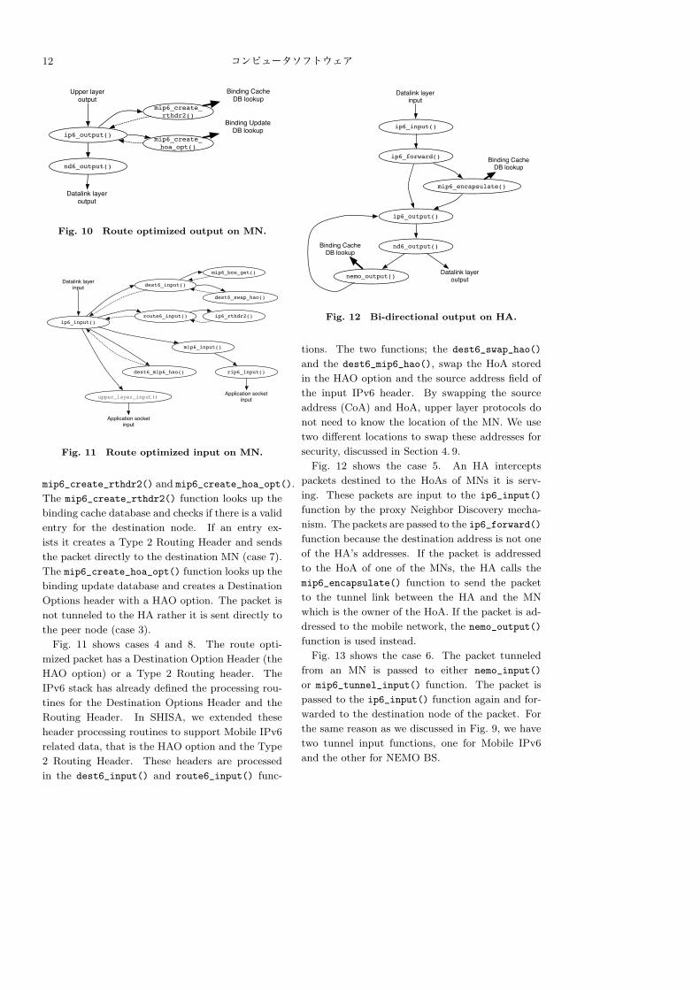
Fig. 10 shows cases 3 and 7. When a
packet is processed in the ip6_output() func-
tion, the function calls two other functions:
12 コンピュータソフトウェア
ip6_output()
nd6_output()
Datalink layer output
Upper layer output
mip6_create_rthdr2()
mip6_create_hoa_opt()
Binding Cache DB lookup
Binding Update DB lookup
Fig. 10 Route optimized output on MN.
ip6_input()
dest6_input()
mip6_input()
route6_input()
mip6_bce_get()
dest6_swap_hao()
dest6_mip6_hao()
upper_layer_input()
ip6_rthdr2()
rip6_input()
Application socket
input
Application socket
input
Datalink layer
input
Fig. 11 Route optimized input on MN.
mip6_create_rthdr2() and mip6_create_hoa_opt().
The mip6_create_rthdr2() function looks up the
binding cache database and checks if there is a valid
entry for the destination node. If an entry ex-
ists it creates a Type 2 Routing Header and sends
the packet directly to the destination MN (case 7).
The mip6_create_hoa_opt() function looks up the
binding update database and creates a Destination
Options header with a HAO option. The packet is
not tunneled to the HA rather it is sent directly to
the peer node (case 3).
Fig. 11 shows cases 4 and 8. The route opti-
mized packet has a Destination Option Header (the
HAO option) or a Type 2 Routing header. The
IPv6 stack has already defined the processing rou-
tines for the Destination Options Header and the
Routing Header. In SHISA, we extended these
header processing routines to support Mobile IPv6
related data, that is the HAO option and the Type
2 Routing Header. These headers are processed
in the dest6_input() and route6_input() func-
ip6_input()
ip6_forward()
nemo_output()
mip6_encapsulate()
nd6_output()
ip6_output()
Binding Cache DB lookup
Binding Cache DB lookup
Datalink layer output
Datalink layer input
Fig. 12 Bi-directional output on HA.
tions. The two functions; the dest6_swap_hao()
and the dest6_mip6_hao(), swap the HoA stored
in the HAO option and the source address field of
the input IPv6 header. By swapping the source
address (CoA) and HoA, upper layer protocols do
not need to know the location of the MN. We use
two different locations to swap these addresses for
security, discussed in Section 4. 9.
Fig. 12 shows the case 5. An HA intercepts
packets destined to the HoAs of MNs it is serv-
ing. These packets are input to the ip6_input()
function by the proxy Neighbor Discovery mecha-
nism. The packets are passed to the ip6_forward()
function because the destination address is not one
of the HA’s addresses. If the packet is addressed
to the HoA of one of the MNs, the HA calls the
mip6_encapsulate() function to send the packet
to the tunnel link between the HA and the MN
which is the owner of the HoA. If the packet is ad-
dressed to the mobile network, the nemo_output()
function is used instead.
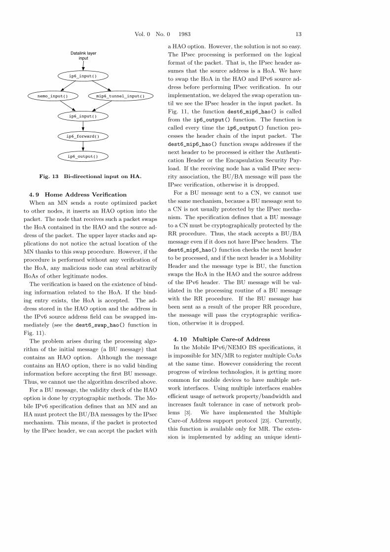
Fig. 13 shows the case 6. The packet tunneled
from an MN is passed to either nemo_input()
or mip6_tunnel_input() function. The packet is
passed to the ip6_input() function again and for-
warded to the destination node of the packet. For
the same reason as we discussed in Fig. 9, we have
two tunnel input functions, one for Mobile IPv6
and the other for NEMO BS.
Vol. 0 No. 0 1983 13
nemo_input() mip6_tunnel_input()
ip6_input()
Datalink layer
input
ip6_forward()
ip6_output()
ip6_input()
Fig. 13 Bi-directional input on HA.
4. 9 Home Address Verification
When an MN sends a route optimized packet
to other nodes, it inserts an HAO option into the
packet. The node that receives such a packet swaps
the HoA contained in the HAO and the source ad-
dress of the packet. The upper layer stacks and ap-
plications do not notice the actual location of the
MN thanks to this swap procedure. However, if the
procedure is performed without any verification of
the HoA, any malicious node can steal arbitrarily
HoAs of other legitimate nodes.
The verification is based on the existence of bind-
ing information related to the HoA. If the bind-
ing entry exists, the HoA is accepted. The ad-
dress stored in the HAO option and the address in
the IPv6 source address field can be swapped im-
mediately (see the dest6_swap_hao() function in
Fig. 11).
The problem arises during the processing algo-
rithm of the initial message (a BU message) that
contains an HAO option. Although the message
contains an HAO option, there is no valid binding
information before accepting the first BU message.
Thus, we cannot use the algorithm described above.
For a BU message, the validity check of the HAO
option is done by cryptographic methods. The Mo-
bile IPv6 specification defines that an MN and an
HA must protect the BU/BA messages by the IPsec
mechanism. This means, if the packet is protected
by the IPsec header, we can accept the packet with
a HAO option. However, the solution is not so easy.
The IPsec processing is performed on the logical
format of the packet. That is, the IPsec header as-
sumes that the source address is a HoA. We have
to swap the HoA in the HAO and IPv6 source ad-
dress before performing IPsec verification. In our
implementation, we delayed the swap operation un-
til we see the IPsec header in the input packet. In
Fig. 11, the function dest6_mip6_hao() is called
from the ip6_output() function. The function is
called every time the ip6_output() function pro-
cesses the header chain of the input packet. The
dest6_mip6_hao() function swaps addresses if the
next header to be processed is either the Authenti-
cation Header or the Encapsulation Security Pay-
load. If the receiving node has a valid IPsec secu-
rity association, the BU/BA message will pass the
IPsec verification, otherwise it is dropped.
For a BU message sent to a CN, we cannot use
the same mechanism, because a BU message sent to
a CN is not usually protected by the IPsec mecha-
nism. The specification defines that a BU message
to a CN must be cryptographically protected by the
RR procedure. Thus, the stack accepts a BU/BA
message even if it does not have IPsec headers. The
dest6_mip6_hao() function checks the next header
to be processed, and if the next header is a Mobility
Header and the message type is BU, the function
swaps the HoA in the HAO and the source address
of the IPv6 header. The BU message will be val-
idated in the processing routine of a BU message
with the RR procedure. If the BU message has
been sent as a result of the proper RR procedure,
the message will pass the cryptographic verifica-
tion, otherwise it is dropped.
4. 10 Multiple Care-of Address
In the Mobile IPv6/NEMO BS specifications, it
is impossible for MN/MR to register multiple CoAs
at the same time. However considering the recent
progress of wireless technologies, it is getting more
common for mobile devices to have multiple net-
work interfaces. Using multiple interfaces enables
efficient usage of network property/bandwidth and
increases fault tolerance in case of network prob-
lems [3]. We have implemented the Multiple
Care-of Address support protocol [23]. Currently,
this function is available only for MR. The exten-
sion is implemented by adding an unique identi-
14 コンピュータソフトウェア
fier field to the MIPM_BUL_ADD, MIPM_BUL_ADD and
MIPM_MD_INFO messages and adding a field to keep
the identifier in the binding databases. The iden-
tifier is bound to each CoA assigned to the MR.
Usually the HA routes packets based on the HoA
of each MR. In this case, the HA cannot distin-
guish the binding between (HoA, CoA1) and (HoA,
CoA2). In this extension, each MR is identified
by the pair of its HoA and an identifier. In the
SHISA implementation, the identifier is mapped to
a tunnel interface. If MR has two network inter-
faces for CoAs and registers these two CoAs at the
same time, the MR and its HA will have two tun-
nel interfaces between them, each tunnel is bound
to each identifier assigned to the network interfaces
of the MR. The MR and the HA can utilize these
tunnels based on local policy. For example, they
can use one tunnel as a primary interface and the
other for backup. Or, if they have two interfaces
which properties are different, e.g. one interface is
low-bandwidth and low-latency, the other is high-
bandwidth and high-latency, then they may use
the former for urgent messages and the latter for
data transmission. Since we have implemented this
mechanism as a tunnel interface, we can use the ba-
sic packet filtering mechanism, such as IP Filter [11]
to distribute traffic.
4. 11 IPv4 Mobile Network Prefix
When NEMO BS was specified, most people in-
volved in the discussion did not think they would
need IPv4 NEMO support. However, considering
the current rate of IPv6 deployment, it will require
more time than we originally expected, therefore
some kinds of IPv4 support will be necessary. We
proposed a mechanism to carry IPv4 traffic over
a tunnel interface created by NEMO BS mecha-
nism [12]. With this mechanism, MR can have
an IPv4 MNP in addition to an IPv6 MNP. The
benefit of this mechanism is that users of an MR,
that supports this extension, can operate IPv4 net-
works over an IPv6 only infrastructure. This kind
of operation encourages the existing IPv4 users to
move IPv6 infrastructure [13], since NEMO BS can
provide fault tolerance and load-balance or traffic
engineering using the Multiple CoA support as dis-
cussed in Section 4. 10. SHISA is extended to keep
IPv4 MNPs in its binding database and extended
to forward IPv4 packets, whose prefix is registered
as a part of MNP, using the tunnel interface estab-
lished between the MR and its HA.
4. 12 SHISA Problems
The main problem for SHISA is its tunneling
mechanism. As discussed in Section 4. 8, SHISA
has two different tunnel mechanisms, one for Mo-
bile IPv6 traffic, the other for NEMO BS traffic.
The former is implemented as an in-kernel tun-
neling mechanism and the latter is implemented
as a pseudo network interface. In Section 4. 10,
we provide the Multiple Care-of Address Registra-
tion function only for MRs. The reason why we
could not provide the same function to Mobile IPv6
comes from the difference in the tunnel design. To
distribute traffic to multiple tunnel interfaces, we
used the IP Filter mechanism. The mechanism
works with the pseudo interfaces but does not work
with the in-kernel tunneling mechanism. We will
have to fix this problem.
4. 13 SHISA Applicability
We have performed various experiments and
demonstrations using the SHISA stack that proves
the applicability of the stack. In 2005, we used our
implementation to provide transparent network ser-
vice in an actual conference network infrastructure
[15]. In 2006, we performed a similar operation at
a conference using the Multiple CoA Registration
mechanism to provide a smoother handover expe-
rience [16]. We also had some demonstration activ-
ities to advertise the IPv6 mobility technology, e.g.
at the First IPv6 Summit in Thailand [14], and the
CEATEC 2006 exhibition which is the largest con-
sumer electronics exhibition in Japan. The SHISA
stack is also used as the base mobility service sys-
tem by the Home Agent Web User Interface activity
[4] [1] in the Nautilus6 project [10].
5 Discussion
We started to implement the Mobile IPv6 stack
as a part of the kernel function. In the beginning,
it seemed to be a better and faster way to create
a working stack, because implementing all func-
tions in the kernel is similar to adding new func-
tions to a single program. Even though the size
of the kernel code is huge, it is a single program.
Since we already had a good foundation in kernel
Vol. 0 No. 0 1983 15
Table9 The code size of each mobility stack
(in line numbers).
KAME Mobile
IPv6
SHISA
kernel (core) 15750 5470
kernel (Mobiliy Socket) n/a 811
user space 3000 17078
programming, through the KAME project activity,
implementing the stack in the kernel shortened the
development time. The first version of the code
was released in October 2001, about 4 months af-
ter beginning of the development. After the spec-
ification became stable around June 2003, when
the final draft of the Mobile IPv6 specification was
published, we started considering the addition of
new features. At this point, the specification was
stable enough and we decided to redesign the en-
tire stack to solve problems we had in the kernel
implementation as described in Section 3. 3. The
new code, SHISA, was implemented mostly as user
space programs with minimum kernel support. The
first release was December 2004, 8 months after be-
ginning. It took twice the time to achieve the ini-
tial release of the stack, however SHISA provides
not only Mobile IPv6 but also NEMO BS from the
beginning. Thanks to the redesigning, we could
implement NEMO BS easily on top of the SHISA
stack. Also, as discussed in Section 4. 10 and 4. 11,
some more new features were added to SHISA later
without big architectural changes.
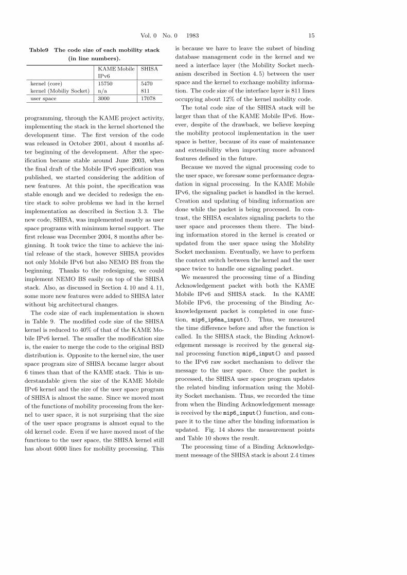
The code size of each implementation is shown
in Table 9. The modified code size of the SHISA
kernel is reduced to 40% of that of the KAME Mo-
bile IPv6 kernel. The smaller the modification size
is, the easier to merge the code to the original BSD
distribution is. Opposite to the kernel size, the user
space program size of SHISA became larger about
6 times than that of the KAME stack. This is un-
derstandable given the size of the KAME Mobile
IPv6 kernel and the size of the user space program
of SHISA is almost the same. Since we moved most
of the functions of mobility processing from the ker-
nel to user space, it is not surprising that the size
of the user space programs is almost equal to the
old kernel code. Even if we have moved most of the
functions to the user space, the SHISA kernel still
has about 6000 lines for mobility processing. This
is because we have to leave the subset of binding
database management code in the kernel and we
need a interface layer (the Mobility Socket mech-
anism described in Section 4. 5) between the user
space and the kernel to exchange mobility informa-
tion. The code size of the interface layer is 811 lines
occupying about 12% of the kernel mobility code.
The total code size of the SHISA stack will be
larger than that of the KAME Mobile IPv6. How-
ever, despite of the drawback, we believe keeping
the mobility protocol implementation in the user
space is better, because of its ease of maintenance
and extensibility when importing more advanced
features defined in the future.
Because we moved the signal processing code to
the user space, we foresaw some performance degra-
dation in signal processing. In the KAME Mobile
IPv6, the signaling packet is handled in the kernel.
Creation and updating of binding information are
done while the packet is being processed. In con-
trast, the SHISA escalates signaling packets to the
user space and processes them there. The bind-
ing information stored in the kernel is created or
updated from the user space using the Mobility
Socket mechanism. Eventually, we have to perform
the context switch between the kernel and the user
space twice to handle one signaling packet.
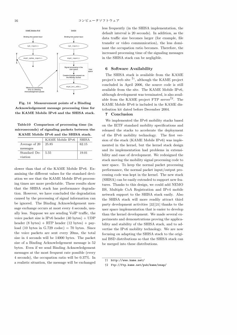
We measured the processing time of a Binding
Acknowledgement packet with both the KAME
Mobile IPv6 and SHISA stack. In the KAME
Mobile IPv6, the processing of the Binding Ac-
knowledgement packet is completed in one func-
tion, mip6_ip6ma_input(). Thus, we measured
the time difference before and after the function is
called. In the SHISA stack, the Binding Acknowl-
edgement message is received by the general sig-
nal processing function mip6_input() and passed
to the IPv6 raw socket mechanism to deliver the
message to the user space. Once the packet is
processed, the SHISA user space program updates
the related binding information using the Mobil-
ity Socket mechanism. Thus, we recorded the time
from when the Binding Acknowledgement message
is received by the mip6_input() function, and com-
pare it to the time after the binding information is
updated. Fig. 14 shows the measurement points
and Table 10 shows the result.
The processing time of a Binding Acknowledge-
ment message of the SHISA stack is about 2.4 times
16 コンピュータソフトウェア
ip6_input()
mip6_ip6ma_input()
KAME Mobile IPv6 SHISA
ip6_input()
mip6_input()
mip6_bul_add()
Binding Ack packet input Binding Ack packet input
Creation/Update request via the Mobility Socket
Signal processing in the user space User
space
Measured processing time of a Binding
Acknowledgement packet
Fig. 14 Measurement points of a Binding
Acknowledgement message processing time for
the KAME Mobile IPv6 and the SHISA stack.
Table10 Comparison of processing time (in
microseconds) of signaling packets between the
KAME Mobile IPv6 and the SHISA stack.
KAME Mobile IPv6 SHISA
Average of 20
messages
25.85 62.15
Standard De-
viation
5.55 19.01
slower than that of the KAME Mobile IPv6. Ex-
amining the different values for the standard devi-
ation we see that the KAME Mobile IPv6 process-
ing times are more predictable. These results show
that the SHISA stack has performance degrada-
tion. However, we have concluded the degradation
caused by the processing of signal information can
be ignored. The Binding Acknowledgement mes-
sage exchange occurs at most every 4 seconds, usu-
ally less. Suppose we are sending VoIP traffic, the
voice packet size is IPv6 header (40 bytes) + UDP
header (8 bytes) + RTP header (12 bytes) + pay-
load (10 bytes in G.729 codec) = 70 bytes. Since
the voice packets are sent every 20ms, the total
size in 4 seconds will be 14000 bytes. The packet
size of a Binding Acknowledgement message is 52
bytes. Even if we send Binding Acknowledgement
messages at the most frequent rate possible (every
4 seconds), the occupation ratio will be 0.37%. In
a realistic situation, the message will be exchanged
less frequently (in the SHISA implementation, the
default interval is 20 seconds). In addition, as the
data traffic size becomes larger (for example, file
transfer or video communication), the less domi-
nant the occupation ratio becomes. Therefore, the
increased processing time of the signaling messages
in the SHISA stack can be negligible.
6 Software Availability
The SHISA stack is available from the KAME
project’s web site †1, although the KAME project
concluded in April 2006, the source code is still
available from the site. The KAME Mobile IPv6,
although development was terminated, is also avail-
able from the KAME project FTP server†2. The
KAME Mobile IPv6 is included in the KAME dis-
tribution kit dated before December 2004.
7 Conclusion
We implemented the IPv6 mobility stacks based
on the IETF standard mobility specifications and
released the stacks to accelerate the deployment
of the IPv6 mobility technology. The first ver-
sion of the stack (KAME Mobile IPv6) was imple-
mented in the kernel, but the kernel stack design
and its implementation had problems in extensi-
bility and ease of development. We redesigned the
stack moving the mobility signal processing code to
user space. To keep the normal packet processing
performance, the normal packet input/output pro-
cessing code was kept in the kernel. The new stack
(SHISA) can be easily extended to support new fea-
tures. Thanks to this design, we could add NEMO
BS, Multiple CoA Registration and IPv4 mobile
network support to the SHISA stack easily. Also
the SHISA stack will more readily attract third
party development activities [22] [21] thanks to the
user space implementation that is easier to develop
than the kernel development. We made several ex-
periments and demonstrations proving the applica-
bility and stability of the SHISA stack, and to ad-
vertise the IPv6 mobility technology. We are now
focusing on adapting the SHISA stack to the origi-
nal BSD distributions so that the SHISA stack can
be merged into these distributions.
†1 http://www.kame.net/
†2 ftp://ftp.kame.net/pub/kame/snap/
Vol. 0 No. 0 1983 17
References
[ 1 ] Andre, M.: A Practical Evaluation of the Nau-
tilus6 Operational Home Agent Service, IPv6 Today
– Technology and Deployment (IPv6TD’07), Inter-
national Academy Research and Industry Associa-
tion, IEEE Computer Society, March 2007.
[ 2 ] Devarapalli, V., Wakikawa, R., Petrescu, A., and
Thubert, P.: Network Mobility (NEMO) Basic Sup-
port Protocol, Technical Report RFC3963, IETF,
January 2005.
[ 3 ] Ernst, T., Montavont, N., Wakikawa, R., Ng,
C., and Kuladinithi, K.: Motivations and Scenarios
for Using Multiple Interface and Global Addresses,
Technical Report draft-ietf-monami6-multihoming-
motivation-scenario-00, IETF, February 2006.
[ 4 ] Fujimaki, S., Shima, K., Uehara, K., and
Teraoka, F.: The Deployment of Mobility Protocols
Based on the Home Agent Service with Easy Inter-
face, Internet Conference 2006 (IC2006), October
2006.
[ 5 ] Jinmei, T., Ito, J., and Sumikawa, M.: Efficient
Use of IPv6 Auto-Configuration in a Mobile Envi-
ronment, The 7th Research Reporting Session, In-
formation Processing Society of Japan, SIG Mobile
Computing, December 1998.
[ 6 ] Jinmei, T., Yamamoto, K., Hagino, J., Sakane,
S., Esaki, H., and Murai, J.: The IPv6 Software
Platform for BSD, IEICE Transactions on Com-
munications, Vol. E86-B,No. 2(2003), pp. 464–471.
[ 7 ] Johnson, D. B., Perkins, C. E., and Arkko,
J.: Mobility Support in IPv6, Technical Report
RFC3775, IETF, June 2004.
[ 8 ] Momose, T., Shima, K., and Tuominen, A.: The
application interface to exchange mobility infor-
mation with Mobility subsystem (Mobility Socket,
AF MOBILITY), Technical Report draft-momose-
mip6-mipsock-00, IETF, June 2005.
[ 9 ] Narten, T., Nordmark, E., and Simpson, W. A.:
Neighbor Discovery for IP Version 6 (IPv6), Tech-
nical Report RFC2461, IETF, December 1998.
[10] Nautilus6 project: August 2007.
http://www.nautilus6.org/.
[11] Reed, D.: IP Filter, Web page, August 2007.
http://coombs.anu.edu.au/˜avalon/.
[12] Shima, K.: IPv4 Mobile Network Prefix Option
for NEMO Basic Support Protocol, Technical Re-
port draft-shima-nemo-v4prefix-01, IETF, October
2005.
[13] Shima, K.: The design and implementation of a
dual-stack mobile network using IPv6 only network
infrastructure, The First International Workshop
on Network Mobility (WONEMO), ICOIN, January
2006.
[14] Shima, K., Kuntz, R., and Mitsuya, K.:
Nautilus6 mobile technology demonstration at
the First IPv6 Summit in Thailand, Technical
Report wide-tr-nautilus6-mobility-demo-thai-ipv6-
summit-00, WIDE Project, July 2006.[15] Shima, K., Uo, Y., Ogashiwa, N., and Uda, S.:
An operational demonstration of a mobile network
with a fairly large number of nodes, The Interna-
tional Symposium on Applications and the Internet
Workshops (SAINTW’06), IEEE Computer Society
and Information Processing Society of Japan, IEEE
Computer Society, January 2006, pp. 6–9.
[16] Shima, K., Uo, Y., Ogashiwa, N., and Uda, S.:
Operational Experiment of Seamless Handover of a
Mobile Router using Multiple Care-of Address Reg-
istration, Academy Publisher Journal of Networks,
Vol. 1,No. 3(2006), pp. 23–30.
[17] Shima, K., Wakikawa, R., Mitsuya, K., Momose,
T., and Uehara, K.: SHISA: The IPv6 Mobility
Framework for BSD Operating Systems, IPv6 Today
– Technology and Deployment (IPv6TD’06), Inter-
national Academy Research and Industry Associa-
tion, IEEE Computer Society, August 2006.
[18] Sklower, K.: A Tree-based Packet Routing Ta-
ble for Berkeley UNIX, Proceedings of the Winter
1991 USENIX Conference, USENIX Association,
January 1991, pp. 93–103.
[19] Soliman, H., Tsirtsis, G., Deverapalli, V.,
Kempf, J., Levkowetz, H., Thubert, P., and
Wakikawa, R.: Dual Stack Mobile IPv6 (DSMIPv6)
for Hosts and Routers, Technical Report draft-ietf-
mip6-nemo-v4traversal-03, IETF, October 2006.
[20] Teraoka, F., Gogo, K., Mitsuya, K., Shibui, R.,
and Mitani, K.: Unified L2 Abstractions for L3-
Driven Fast Handover, Technical Report draft-irtf-
mobopts-l2-abstractions-01, IETF, September 2006.
[21] Vogt, C.: Early Binding Updates for Mobile
IPv6, Technical Report draft-vogt-mobopts-simple-
ebu-00, IETF, August 2006.
[22] Vogt, C. and Arkko, J.: Credit-Based Au-
thorization for Concurrent Reachability Verifica-
tion, Technical Report draft-vogt-mobopts-simple-
cba-00, IETF, August 2006.
[23] Wakikawa, R., Ernst, T., and Nagami, K.:
Multiple Care-of Addresses Registration, Techni-
cal Report draft-wakikawa-mobileip-multiplecoa-05,
IETF, February 2006.
[24] WIDE project: KAME Working Group, March
2006. http://www.kame.net/.
[25] WIDE project: SHISA, February 2007.
http://www.mobileip.jp/.