designing and simulating a smart sars-cov-2 air purifier
TRANSCRIPT

Designing and Simulating a Smart SARS-CoV-2Air Purifier
Noah Bergam Lily [email protected] [email protected]
Sakshi Lende Skyler Snow Julianna [email protected] [email protected] [email protected]
Michael J DiBuono* Nicholas J Calzaretto*[email protected] [email protected]
New Jersey’s Governor’s School of Engineering and TechnologyJuly 18, 2020
*Corresponding Author
Abstract—The airborne nature of COVID-19 transmissionhas rendered indoor gatherings particularly risky due to theconcentrated airflow in areas both with and without heating,ventilation, and air conditioning (HVAC) systems. This paperproposes a compact, smart air purification module meant tocreate isolated pockets of air for separate groups around tables.Multiple techniques for killing the SARS-CoV-2 virus wereconsidered for the module, and it was decided that a HighEfficiency Particulate Air (HEPA) filter would be used to capturethe aerosolized virus and a ultraviolet C light-emitting diode(UVC LED) would be used to routinely clean said filter. Thismodule’s structure was outlined using Computer Aided Design(CAD), its Internet of Things (IoT) networking capabilities weredesigned using microcontrollers and a mobile application, andits potential impact was modeled using computational fluiddynamics (CFD). The module was found to prevent contaminatedair from spreading between tables in spaces both with andwithout HVAC systems.
I. INTRODUCTION
In July 2020, the Center for Disease Control (CDC) pub-lished an investigation which traced an early outbreak ofCOVID-19 back to a restaurant in Guangzhou, China, andconcluded that the air conditioning system of the buildingenabled the micro-droplet, or aerosol, transmission of the virusbetween table groups (Fig. 1) [1]. In response to this and sim-ilar events, the World Health Organization has acknowledgedthe potentially airborne transmission of SARS-CoV-2 [2].These developments have helped solidify a general consensusamong experts that HVAC systems, although safer than a lackthereof, can still contribute to airborne transmission of SARS-CoV-2 due to their large-scale manipulation of airflow [3].
This project sets out to design an air purification modulewhich, if used in a distributed manner, can address the trans-mission risk posed by HVAC systems in public indoor areas.
This module would principally consist of a fan and an antiviralair filter: the former would drive a contained, convection-likeairflow around a table, and the filter would eliminate SARS-CoV-2 from the air. For optimal performance, every table ina given room would have a module. The hypothesized effect,later explored in simulations, would be a smaller chance ofcontaminated air spreading between tables.
Fig. 1. CDC sketch of the Guangzhou restaurant where a COVID-19 outbreakis believed to have originated in early 2020 [1].
The costs, energy consumption, size constraints, and struc-tures of potential air purifier designs are considered in select-ing one of the potential disinfection methods. Upon selectionof a method, the electronics and networking capabilities ofthe module are framed out, and the airflow of the model isexperimentally examined using CFD simulation to determinethe impact of the module in the presence of people as well asHVAC systems.
1

II. BACKGROUND
A. Copper
The reason for copper’s historically well-known antimicro-bial properties is because of its electron configuration. Coppercontains a lone valence electron which enables it to easilyparticipate in several oxidation-reduction reactions that areharmful to cellular molecules [4]. When coming into contactwith a microbe, copper releases highly reactive ions that seekand puncture cell membranes and viral coatings, targetingDNA and RNA to prevent mutations and render microbes inac-tive [5]. Modern applications of antimicrobial copper includehigh-traffic touch surfaces such as doorknobs, often used inhigh-risk settings such as hospitals [4]. More recently, copperhas been tested as a possible face mask component againstSARS-Cov-2 [6]. However, it was concluded that copper wasnot a viable solution because copper requires four hours ofcontinuous contact to inactivate SARS-Cov-2, and is thereforeless effective for aerosol uses. Existing face masks that incor-porate copper-infused woven fabric lack antiviral effectivenessbecause copper air filters are incapable of capturing all viralparticles. The finest copper filters available have a pore size of100nm [7], and SARS-Cov-2 ranges from 60-140nm in size[8] [9] [10].
B. Nickel Foam
SARS-CoV-2, as a microbe, is susceptible to temperaturevariation [11]. At temperatures significantly above 70°C,SARS-CoV-2 inactivates almost instantly. Specifically, thevirus’ membrane protein is particularly susceptible to thermalaggregation [12], and its nucleocapsid protein has low stabilityand fully denatures at 55°C [13]. These proteins are essentialfor viral function, rendering SARS-CoV-2 more vulnerable tohigh temperatures than other coronaviruses.
Recently, a heated air disinfection system based upon nickelfoam filters electrically heated to 200°C was developed byHouston researchers [14]. This catch-and-kill system elimi-nates 99.8% of aerosolized SARS-CoV-2 viral load in a singlepass through the filter. Surprisingly, the heated nickel filtersdo not significantly affect ambient temperature. However, a20mm x 250mm x 1.6mm strip of nickel foam requires 480Wto reach 200°C [11]. Batteries able to provide that wattagefor extended periods of time are too large for use in aportable air purifier. Therefore, while mobile air purificationdevices were mentioned as a possible future application [11],it was concluded that heated nickel filters would likely bemore effective when integrated into centralized air purificationsystems.
C. UV Light
Ultraviolet radiation damages the genome of viruses suchas SARS-CoV-2 by breaking bonds and forming photodimericlesions in ribonucleic acids, preventing transcription and repli-cation [15]. Other viral components, including proteins, arealso impaired by ultraviolet radiation, rendering the virusinactive due to its inability to complete essential biological
functions such as attachment and penetration [16]. Four pro-teins constitute the structure of SARS-CoV-2, without whichviral structure is lost [16]. The germicidal range for ultravioletradiation ranges from 200-300nm, with peak effectivenessaround 265nm [17]. This wavelength falls within the rangefor UVC, a form of ultraviolet radiation that does not produceharmful ozone [18].
Ultraviolet C is incredibly dangerous to humans because ofits short wavelength compared to other forms of ultravioletradiation, possibly causing acute photokeratitis, prematureskin aging, and cancer. However, UVC is easily absorbedby plastics and other materials. With proper measures, UVCcan be used safely within close proximity to humans whilepreventing harmful exposure [19]. A UVC dose of 1.5J/cm2
was determined to be an effective method of sterilizing N95respirators that were inoculated with SARS-CoV-2 [20]. UVCradiation can be artificially produced with light emitting diodes(LEDs). Therefore, it was concluded that because UVC LEDsare smaller and more energy efficient, they are ideal forportable use in the module [17].
D. Computational Fluid Dynamics
Due to limitations on computational power and accessto software, the simulation of the air purification module’sexternal airflow was confined to static, 2D graphs in Python,enabled with the NumPy and Matplotlib libraries. The simu-lations are based on a 2D version of the Navier-Stokes fluidequations for an incompressible fluid. In every time step, threesecond-order differential equations were considered: two gov-erning the velocity components and one governing pressure.The equations read as such:
∂u
∂t+ u
∂u
∂x+ v
∂u
∂y= −1
ρ
∂p
∂x+ v(
∂2u
∂x2+∂2u
∂y2)
∂v
∂t+ u
∂v
∂x+ v
∂v
∂y= −1
ρ
∂p
∂y+ v(
∂2v
∂x2+∂2v
∂y2)
∂2p
∂x2+∂2p
∂y2= −ρ(∂u
∂x
∂u
∂x+ 2
∂u
∂y
∂v
∂x+∂v
∂y
∂v
∂y)
where x is horizontal position, y is vertical position, u isx-velocity, v is y-velocity, and ρ is density [21].
These equations arise from the application of Newton’sSecond and Third Laws to arbitrarily small cells of fluid. Themodel accounts for force due to pressure gradient and viscosity[21]. Gravity was deemed negligible.
These equations were discretized in Python, using 0.001stime steps and a 10,000 cell grid, and the final result of thesimulation is a list showing the corresponding u, v, and p foreach cell of fluid at a specific point in time. The plots of thisdata were visualized in two different formats (Fig. 2). In orderto define boundaries in this space, a set of points were pickedout and set at zero velocity at all time steps.
2

The airflow from the module’s fan was modeled using apermanent upward velocity at a given point, which wouldproceed to create a pressure gradient and mimic the upwardfan flow characteristic of the proposed module.The speed (v)of the air coming out the fan was set to 1.59 m/s. This speedwas found using the following equation:
v = CFM/πr2
where CFM is cubic feet of air per minute moved bythe fan 0.01m3/s and r is the radius of the fan 0.046m. Thisinformation was known from the design specifications of thepurchased fan [27].
Fig. 2. Vector field visualization (left) shows the magnitude and direction ofvelocity at each point. The streamplot (right) connects the vectors to showlarger scale airflow (at the expense of showing relative magnitudes). Bothplots use color to denote pressure differences (pressure bar not shown).
III. METHODOLOGY
A. Implementing the COVID-treatment Method
While ultraviolet C radiation can kill aerosolized SARS-CoV-2 particles, it requires a duration of exposure that isdifficult to provide when air is quickly flowing past theirradiated area. With a fan flow rate of 0.63m3/min and aninternal volume of 0.00182m3, air would remain within themodule for only 0.173s. Furthermore, microorganisms, whenexposed to UVC irradiation, will be killed or decreased inpopulation at a rate according to a first order equation [23]:
S(t) = e−kIt
where k is the standard rate constant (cm2/µJ), I is the UVintensity (µW/cm2), and t is the time of exposure (s).
The rate constant k is unique to each microorganism anddefines its sensitivity to UVC radiation. The rate constantfor SARS-CoV-2 is highly inconsistent in recently publishedliterature as it is highly dependent on various factors such asinoculum size and culture medium [24]. From the equation, itis known that t has an inverse exponential relationship with S.Increasing the time of exposure to UVC radiation decreasesthe microbial population. I also has an inverse exponentialrelationship with S. Increasing the UVC intensity by raisingthe LED wattage decreases the microbial population. Becauseof battery limitations, increasing the LED wattage is unviable.
Therefore, increasing exposure time is necessary to signifi-cantly decrease the SARS-CoV-2 population passing throughthe module. Increasing exposure time can be accomplishedby trapping aerosolized viral particles in the module whilethe remaining air passes through. As aforementioned, HEPAfilters can capture over 99.99% of particles the size of SARS-CoV-2 [26]. By shining the UVC LED on a HEPA filter,viral particles can remain irradiated indefinitely. SARS-CoV-2has a D90 dose of 0.00123J/cm2 [26], meaning that 90% ofSARS-CoV-2 is inactivated in 0.0889s of 1W UVC exposure.However, significantly higher doses of UVC radiation arerequired to guarantee air safety. While the minimum infectiousdose of SARS-CoV-2 is still unknown, it is predicted to bevery low due to the virus’ high infectiousness, with someexperts estimating that as few as 1000 viral particles areenough to cause infection. Because a single cough or sneezecan release up to 200,000,000 SARS-CoV-2 viral particles intothe environment [28], far higher levels of viral populationreduction are required to guarantee that the filter does notoutput infectious doses of viral particles. UVC radiation atthe dose of 1.5J/cm2 has been proven to fully decontaminateN95 respirators [29]. These respirators have similar material,structure, and function to HEPA filters. Therefore it wasconcluded that for full decontamination of an 8.5cm x 8.5cmHEPA filter with a 1.5J/cm2 dose, a 1W UVC LED mustradiate for 108.375s.
B. Module Designs and Evaluation
1) CAD Design: The technical specifications of each cus-tom component can be found in the Appendix.
Computer Aided Design (CAD) is a process involvingcomputerized software to design, develop, and document aproduct. SolidWorks is a CAD software primarily used inthe engineering industry and was utilized for this projectto design and model the product’s structure. This softwarewas used for the creation of an external shell and internalcomponents that were critical to the structure of the product,and made it possible to create a final image of the product’sdesign with all components assembled. The use of CADalso allowed for animations and seeing moving parts priorto construction, making it easy to identify design flaws. Theouter shell, fan, filter, and UVC light were designed in separateSolidWorks files, then combined into one assembly. Usingtechnical drawings from NBM Technologies [27], the designfor the fan was replicated in SolidWorks to create a realisticand to-scale model of the product.
The fan’s blades are 31.66mm long and the inner hub hasa radius of 38.35mm (Figure 20). The fan casing has anouter dimension of 100mm and an inner blade insert with aradius 95.23mm (Figure 21). Both components were createdin separate parts and then combined into an assembly, usingthe inner hub as the main point for the rotational mate. Thefan and casing are plastic parts, making them lightweight, butstill able to create a strong air current.
The UVC LED light was also replicated using dimensionsfrom an online retailer [31]. It has a light of radius 2.1mm
3
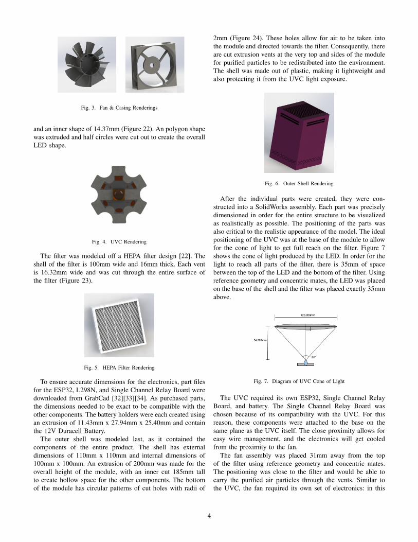
Fig. 3. Fan & Casing Renderings
and an inner shape of 14.37mm (Figure 22). An polygon shapewas extruded and half circles were cut out to create the overallLED shape.
Fig. 4. UVC Rendering
The filter was modeled off a HEPA filter design [22]. Theshell of the filter is 100mm wide and 16mm thick. Each ventis 16.32mm wide and was cut through the entire surface ofthe filter (Figure 23).
Fig. 5. HEPA Filter Rendering
To ensure accurate dimensions for the electronics, part filesfor the ESP32, L298N, and Single Channel Relay Board weredownloaded from GrabCad [32][33][34]. As purchased parts,the dimensions needed to be exact to be compatible with theother components. The battery holders were each created usingan extrusion of 11.43mm x 27.94mm x 25.40mm and containthe 12V Duracell Battery.
The outer shell was modeled last, as it contained thecomponents of the entire product. The shell has externaldimensions of 110mm x 110mm and internal dimensions of100mm x 100mm. An extrusion of 200mm was made for theoverall height of the module, with an inner cut 185mm tallto create hollow space for the other components. The bottomof the module has circular patterns of cut holes with radii of
2mm (Figure 24). These holes allow for air to be taken intothe module and directed towards the filter. Consequently, thereare cut extrusion vents at the very top and sides of the modulefor purified particles to be redistributed into the environment.The shell was made out of plastic, making it lightweight andalso protecting it from the UVC light exposure.
Fig. 6. Outer Shell Rendering
After the individual parts were created, they were con-structed into a SolidWorks assembly. Each part was preciselydimensioned in order for the entire structure to be visualizedas realistically as possible. The positioning of the parts wasalso critical to the realistic appearance of the model. The idealpositioning of the UVC was at the base of the module to allowfor the cone of light to get full reach on the filter. Figure 7shows the cone of light produced by the LED. In order for thelight to reach all parts of the filter, there is 35mm of spacebetween the top of the LED and the bottom of the filter. Usingreference geometry and concentric mates, the LED was placedon the base of the shell and the filter was placed exactly 35mmabove.
Fig. 7. Diagram of UVC Cone of Light
The UVC required its own ESP32, Single Channel RelayBoard, and battery. The Single Channel Relay Board waschosen because of its compatibility with the UVC. For thisreason, these components were attached to the base on thesame plane as the UVC itself. The close proximity allows foreasy wire management, and the electronics will get cooledfrom the proximity to the fan.
The fan assembly was placed 31mm away from the topof the filter using reference geometry and concentric mates.The positioning was close to the filter and would be able tocarry the purified air particles through the vents. Similar tothe UVC, the fan required its own set of electronics: in this
4

Fig. 8. Assembly View of Electronics
case an ESP32, L298N, and battery. The L298N was chosenbecause of its compatibility with the fan. These componentswere attached above the fan to allow for easy wiring accessand would also be cooled from the proximity to the fan.
Fig. 9. Assembly View
Figure 10 shows an exploded view of the complete assem-bly, with the components aligned at their respective heightlocations in the module.
Fig. 10. Assembly Exploded View
2) Integrating Parts and Electronics: The entire moduledesign consists of one fan, one fan motor, one HEPA filter,one UVC LED, two batteries, two microcontrollers, one motordriver, one electromagnetic relay, and one outer shell.
As airflow is essential to the effectiveness of a filter, acommercial axial fan was selected in order to provide airflow.The fan selected included both fan blades and a motor [27] andis about 80mm x 80mm x 15mm. Although many householdfans are powered using an AC current, a fan that could be
powered with a DC current was chosen in order to maintainthe viability of the module as a portable item.
For the axial fan’s power, which was 12V, a 12V commercialbattery was selected [35].
The same 12V commercial battery [35] was chosen to powerthe two microcontrollers [48, 39, 40] and the UVC light [31]within the module design.
C. Smart Functionality
The core of the smart system lies in a Wi-Fi controlled IoTnetwork amongst every device that can be controlled remotelywith a mobile application. An application was designed forAndroid devices using MIT App Inventor and would allowbusiness staff to control two features of each device acrossthe location within 1km range: (1) the power state of the fanmovement and (2) the power state of the UVC Light. Thisfeature is shown in Figure 11, where each table has an onand off switch for the fan and the UVC light. The applicationutilizes the MIT Connectivity Feature to communicate withthe ESP32.
Fig. 11. UI of the app
1) IoT Scheme for Fan: The ESP32 (a microcontroller withintegrated Wi-Fi and Bluetooth capabilities) is the core of theIoT Connection and contains the downloaded Arduino code,which the application controls through web connectivity tothe ESP32’s IP Address. As shown in Fig. 12, When theESP32 receives the signal from the app, it would output aPWM pulse to L298N to drive the DC fan, activating the fullfiltration function. The ESP32 and the L298N motor driver areconnected to a stabilized battery source.
2) IoT Scheme for UVC LED: Here, a separate ESP32, withthe downloaded Arduino data and code, is the core of this UVCLED IoT system. The application activates the ESP32 throughweb connectivity to its IP address, allowing the business ownerto turn on the UVC light to clean the filter at any time. TheESP32 is then able to connect and turn off the UVC bulbthrough the Electromagnetic 5V Relay (shown in Fig. 13).The ESP32 and the UVC bulb are connected to a stabilizedbattery power source.
5

Fig. 12. This electronics diagram demonstrates the more detailed process.Note that the stabilized power source 12V is a battery.
Fig. 13. 5V Relay for the UV Light.
D. Airflow Modeling
These simulations were concerned with demonstrating thecapabilities and limitations of the module in regards to filteringparticulate air and creating safe airflow, both on a table leveland a broader room level. For the purposes of evaluation, thissection considers a simple, virtual indoor restaurant, consistingof four tables. Each table surface is a circle with a one-meterdiameter, and the tables are in a square formation, where thetables, end-to-end, are 2m apart, in keeping with lower-riskindoor dining suggestions by the CDC (see Fig. 14 for moredetails) [30].
Fig. 14. The virtual setting of the airflow case study. The dimensions of theroom were 6m x 6m x 2.5m. In some simulations it will have a ventilationrunning through the vents shown.
1) General Particulate Air Filtration: The main purpose ofthe module is not its particulate air filtration of large spaces.This expectation was explored by calculating the air changesper hour, or ACH, of the module in the theoretical room. ACHis calculated as follows:
ACH = CFM ∗ 60/V
where CFM is cubic feet per minute moved by the fan,and V is the volume of the room [30]. CFM was obtainedfrom the fan information sheet to be 22.25ft3/min, and volumewas 90m2 [27].
It was found that four of the modules in the room with noother air conditioning system would have an ACH of about 1.7,less than the general benchmark of 4 for ACH in commercialbuildings and well below the 10 to 15 range for cafeteria areas[43, 44]. As such, the module should be used in tandem withan HVAC system to ensure maximum air quality. The moduleis not a substitute but rather a supplement for a full ventilationsystem, and the supplemental value is due to the localized wayit moves air around a table environment.
2) Airflow Around a Table: With an airborne disease likeCOVID-19, human breath, in the form of coughing, sneezing,or exhalation, is the vector that must be quickly and effectivelytreated in order to fight transmission. No matter how high itsCFM or ACH, a large HVAC system will spread this vectoraround a room, as seen in Guangzhou, and possibly recirculateit to other parts of the building. The proposed module on atable, however, can simplify this issue by creating a localized,cyclical airflow around a table.
A simulation was made which monitored the airflow be-tween the module and a breathing person sitting at the table(Fig. 15).
Fig. 15. Baseline airflow, with no breathing from the person and the modulerunning.
This simulation was run under two scenarios: one wherethe person was breathing normally, and one where the personsneezed or coughed. Breath speed was modeled with thefollowing sinusoidal function:
u = 2.2sin(2πt/3000)
where u is the speed of the person’s breath (all horizontal),and t is the time in milliseconds. Note how the function modelsthe maximum speed of breath as 2.2m/s and the period ofbreathing as 3s. These numbers fall well into the observedranges of human breath behavior [36].
6

Both the inhale and the exhale led to slight disruptions in themodule’s airflow, but ultimately they fit into the cyclical modelof the purifier. Freshly cleaned air was taken in on the inhale,and possibly contaminated air was immediately directed to themodule to be disinfected (Fig. 16).
Fig. 16. Peak exhale (top) and inhale (bottom) airflow.
The sneeze experiment was run under two conditions: onewith the module, and one without. The sneeze was modeledto have a speed of 6m/s for 0.4s, which was an intendedoverestimation of both the speed and duration of a real sneeze[37]. Without the module, the sneeze propagated quickly andblew contaminated air to the other end of the table andbeyond (Fig. 17, top). After the sneeze ended at t = 0.4s,the contaminated air entered a stable cyclical flow due tothe unrealistically isolated nature of the experiment (Fig. 17,bottom). In real life, the sneeze would diffuse faster andfarther, especially with the help of background HVAC currents,and thus possibly spread germs to other tables.
With the module in place, the airflow was disrupted by thesneeze but quickly stabilized by the steady airflow patternof the purifier. After the sneeze ended, the overall airflowappeared rotated counterclockwise (Fig. 18, top), but quicklystabilized such that t = 1.0s (Fig. 18, bottom) looked like thecontrol situation. This simulation cannot rule as to whether allsneeze particles were caught by the purifier, but compared tothe no-module scenario, there is quick localization of airflow,as opposed to slow diffusion, which would ostensibly reducerisk.
These two simulations together provide a proof-of-conceptfor how this module can isolate airflow around a table andquickly treat human breath in response to both a normal
Fig. 17. Progression of sneeze without the module. Note the chaotic airflowat t = 0.4s, followed by the diffusion into a larger cyclical pattern by t = 1.5s.
Fig. 18. The progression of the sneeze with the module. Top shows sneezeat t = 0.7s, and how the module stabilizes the airflow between that point andt = 1.0s. Not shown is the airflow during the sneeze (t = 0s to t = 0.4s) whichlooked almost identical to the airflow seen in the situation without the module.This result was likely because the force of the sneeze heavily disturbed thatof the module for that short duration.
breathing pattern and a sneeze situation.
7

3) Airflow with Background AC: The second simulationconsidered the airflow of a vertical cross section of the roomalong two tables and too opposite AC vents. The goal wasto visualize the airflow between the two tables and how itchanges in the presence of the AC. The AC is modeled as avelocity inlet on one end and a velocity outlet on the other,and the speed of it is set at 3m/s, which is characteristic ofmaximum airflow in low to medium loss ducts [35].
It was found that the airflow of the modules was heavilydistorted with the AC at 3m/s, although the airflow differsheavily between the placement of the vents (Fig. 19). Thedistortion was reduced but not fully eliminated with slowerAC speeds, which were tested down to a fairly unrealistic 1:1ratio between module speed and vent speed.
Fig. 19. Airflow with module on and AC flow entering and exiting. Topshows both vents near the floor, bottom shows outlet vent near the ceiling.
Human models were then placed at each table in differentconfigurations, with different ventilation structures and inhala-tion and exhalation speeds, and the air currents were tracked.In all situations where the filter was implemented, the air froma person’s breath was quickly brought to their correspondingfilter, and no clear line of transmission along the streamplotwas identified (Fig. 20). Tracing the streamplot was deemedan effective way of determining a viable line of transmissionsince, over time, the streamplot lines tended to stay fairlyconsistent over time. While not entirely true to the dynamicnature of airflow, this method presumably offered a decentidea of where air, and thus potential SARS-CoV-2 aerosols,could go in future moments.
Ultimately, despite the distortion caused by the HVACsystem, it was found that the airflow between tables was stilllargely isolated and thus the transmission risk was ostensiblyreduced. The ultimate success of the module demonstrates howthe air purifier and an AC system can coexist and manageto maintain a balance between high ACH and localized airpurification.
4) Limitations: By looking at simple geometries in 2D,these simulations make numerous simplifications about real-
Fig. 20. An example of how the module can prevent a possible COVID-19transmission. The top graph (no modules) shows an exhaler and an inhaler onopposite ends of the room, and how the AC current creates a very clear pathof contaminated air from left to right. The bottom graph has modules on eachtable, and shows how the air from the exhaler is cleaned before reaching theother end of the room.
life airflow. However, due to the symmetry of tables and theairflow current that the purifier creates, the patterns observed inthe 2D cross sections can provide a general overview of whathappens in 3D. As such, these simulations, while imperfect,still provide a valid proof-of-concept for the module’s abilitiesto create isolated airflow around tables.
E. Conclusions and Future Directions
By isolating and decontaminating the air both around andbetween tables, the proposed module has the potential to makea safer environment for indoor areas with groups of peoplearound tables, such as dining areas, schools, and offices. Ifused on a large enough scale, this module could significantlyaid public health initiatives around the world as quarantinerestrictions are relaxed and public life is resumed.
Further development of this module would include creatingand testing a physical prototype of the air purifier, first asan individual module and then as part of a larger network ofmodules in an entire building. Once the module is ready forlarge-scale production, the manufacturing process would beassessed and optimized to ensure cost-efficiency and quality.
In order to more accurately quantify and visualize themodule’s impact, 3D CFD with more true-to-life geometrieswould be simulated in varying situations. Such experimentscould track a cloud of SARS-CoV-2 aerosol particles froman infected person and more precisely quantify where theygo in situations with and without the module. Using someapproximations, these results could feed into a larger diseasemodel to show how many cases this technology could reduceover an extended period of time. Other analyses could exist ona smaller scale and examine the internal airflow of the moduleand how that affects its external presence.
8

Furthermore, the application UI would be improved beyondthe prototyping software of MIT App Inventor to contain inter-active visuals, like dining tables. Additionally, the applicationcould be expanded into other platforms beyond Android, suchas Apple iOS application or web domain. The applicationcould also include in-application data reports and trackingof device, energy usage, and possibly air flow analysis. Ul-timately, the further vision for this project revolves arounddeveloping a professional, industry standard application tocontrol these devices and offer maximal accessibility and smartfunctionality for the user.
APPENDIX
The CFD code can be accessed here:www.github.com/nbergam2021/COVID-Air-Purifier.
Fig. 21. Fan Technical Drawing
Fig. 22. Casing Technical Drawing
Fig. 23. UVC LED Technical Drawing
Fig. 24. HEPA Filter Technical Drawing
Fig. 25. Outer Shell Technical Drawing
9

ACKNOWLEDGMENTS
The authors of this paper would like to graciously thankthe following: Project Liaison and Research Coordinator Ben-jamin Lee for his invaluable guidance over the course ofthe research process; Project Mentors Nicholas Calzaretto,Michael DiBuono, Morgan Taylor, Kyle Clark, James Ramos,and Marissa DelRocini of Lockheed Martin for their vastknowledge of engineering and product development; Directorof GSET Dean Jean Patrick Antoine, Director Emeritus ofGSET Dean Ilene Rosen, and Head RTA Rajas Karagikar fortheir passionate leadership and guidance; Rutgers University,Rutgers School of Engineering, Lockheed Martin, the NewJersey Space Grant Consortium, and the State of New Jerseyfor their sponsorship; and lastly NJ GSET Alumni, for theircontinued participation and support.
REFERENCES
[1] “COVID-19 Outbreak Associated with Air Conditioning in Restaurant...”.
[2] A. Mandavilli, ”239 Experts With One Big Claim: The Coronavirus IsAirborne”, The New York Times, 2020.
[3] T. Dunn, “Can Air Conditioning Transmit the Coronavirus?,” Wirecutter,2020.
[4] “Metal-based antimicrobial strategies”.[5] “Copper’s Virus-Killing Powers Were Known Even to the Ancients”.[6] “Copper Won’t Save You From Coronavirus - The New York Times”.[7] K. Rubow L., B. Huang, M. Wilson, E. Mahon, and M. Corporation,
“HOT GAS FILTRATION USING SINTERED METAL FILTERS”.Mott Corporation, Nov.-2006.
[8] Intertek Testing Services, Copper Clothing, 2020.[9] “Copper Face Mask”.
[10] “How large is a corona virus virion compared to the MP10-2.5 ...”.[11] “Catch and kill airborne SARS-CoV-2 to control spread of COVID-19
...”.[12] “Thermal aggregation of SARS-CoV membrane protein”.[13] Y. Wang, “Low Stability of Nucleocapsid Protein in SARS Virus†”.
ACSPublications.[14] “Researchers create air filter that can kill the coronavirus”.
[15] Comparison of UV-Induced Inactivation and RNA Damage in MS2Phage across the Germicidal UV Spectrum. American Society forMicrobiology.
[16] A. Katsnelson, “What do we know about the novel coronavirus’s 29proteins?”.
[17] ”How to Light: How effective are UVC LEDs? - Lux Review”, LuxReview, 2017.
[18] ”WHY UV-C CANNOT PRODUCE OZONE”, UVResources.[19] K. Kahn, ”Is UVC Safe?”, Klaran.[20] ”The Effect of Ultraviolet C Radiation Against SARS-CoV-2 Inoculated
N95 Respirators”, medRxiv, 2020.[21] ”Navier-Stokes Equations”, National Aeronautics and Space Adminis-
tration, 2020.[22] ”LifeAir Air Filter 12”x20”x1” Antiviral Anti-allergen Washable HEPA
100% MADE IN USA”, Amazon.com, 2020.[23] ”Mathematical Modeling of Ultraviolet Germicidal Irradiation for Air
Disinfection”, Berriman, 2020. [Accessed: 19- Jul- 2020].[24] ”Rapid evidence summary on SARS-CoV-2 survivorship and disinfec-
tion, and a reusable PPE protocol using a double-hit process”, Medrxiv,2020.
[25] ”2020 COVID-19 Coronavirus Ultraviolet Susceptibility”, Research-Gate, 2020.
[26] J. Perry, J. Agui and R. Vijayakimar, ”Submicron and NanoparticulateMatter Removal by HEPA-Rated Media Filters and Packed Beds ofGranular Materials”, Ntrs.nasa.gov, 2020.
[27] Newark. 2020. 08015JE-12M-BA-F0.[28] ”COVID-19: Transmission Scenarios Explained”, Govtech.com, 2020.[29] Ozog, D., 2020. The Effect Of Ultraviolet C Radiation Against SARS-
Cov-2 Inoculated N95 Respirators.[30] ”Communities, Schools, Workplaces, & Events”, Centers for Disease
Control and Prevention, 2020.[31] ”CE certified 1 watt 265nm uvc led for germicidal led uv sterilizer
wholesale price”, www.alibaba.com, 2020.[32] H. Shuja, ”ESP32-PICO-KIT”, GrabCAD, 2020.[33] D. Barker, ”L298N H-Bridge Motor Driver”, GrabCAD, 2020.[34] G. Tkouri, ”Single 5V relay board”, GrabCAD, 2020.[35] Amazon.com, 2020. [Online]. Available:
https://www.amazon.com/Duracell-Security-21-Count-Pack/dp/B00005T3E3. [Accessed: 18- Jul- 2020].
[36] ”Human exhaled air energy harvesting with specific reference to PVDFfilm”, ScienceDirect, 2017.
[37] D. Engber, ”FYI: How Forceful Is A Sneeze?”, Popular Science, 2020.
10