designing for plastics: optimizing your injection … · ... optimizing your injection ......
TRANSCRIPT
Designing for Plastics: Optimizing Your Injection Molded Parts
www.xcentricmold.comCopyright © Xcentric Mold & Engineering 2
In the mid 90’s, two Michigan-bred brothers working for other companies as mold makers realized that all the mold shops in the Detroit area lacked technology and relied primarily on traditional and more manual processes. In 1995, they decided that the only way to differentiate from their peers in the trade was to learn and apply technology on their own and Xcentric Mold & Engineering was born.
They built a proprietary advanced technology platform focused on software, automation, systems, and custom standardization and processes – it would become the foundation that would surpass all other traditional manufacturing companies. Employees were hand-picked and trained through a rigorous
advanced mold making program that the founders created so each individual could speak technically and with confidence to customers on the fly. The art of mold making was transformed into the science of custom quick-turn manufacturing and Xcentric Mold & Engineering of today where quality, design and speed are not compromised.
The brothers knew they created something special. Because of their vision and strong belief in utilizing and creating technology, processes and systems along with building a team of professionals, Xcentric was able to compete even when jobs were being lost to lower labor countries overseas. And when the bottom fell out in the economy in 2009 it had very little effect on the company. A story of two brothers, a vision realized through courage and innovation combining the art and science of mold making, leading to over 20 years of experience as Xcentric Mold & Engineering.
Our Story
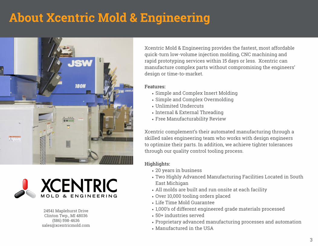
Xcentric Mold & Engineering provides the fastest, most affordable quick-turn low-volume injection molding, CNC machining and rapid prototyping services within 15 days or less. Xcentric can manufacture complex parts without compromising the engineers’ design or time-to-market.
Features:• Simple and Complex Insert Molding• Simple and Complex Overmolding• Unlimited Undercuts• Internal & External Threading• Free Manufacturability Review
Xcentric complement’s their automated manufacturing through a skilled sales engineering team who works with design engineers to optimize their parts. In addition, we achieve tighter tolerances through our quality control tooling process.
Highlights:• 20 years in business• Two Highly Advanced Manufacturing Facilities Located in South
East Michigan• All molds are built and run onsite at each facility• Over 10,000 tooling orders placed• Life Time Mold Guarantee• 1,000’s of different engineered grade materials processed• 50+ industries served• Proprietary advanced manufacturing processes and automation• Manufactured in the USA
24541 Maplehurst DriveClinton Twp., MI 48036
(586) [email protected]
3
About Xcentric Mold & Engineering
www.xcentricmold.comCopyright © Xcentric Mold & Engineering 4
Before we jump into designing for plastics, here’s a quick review of the Injection Molding Process and Rapid Injection Molding.
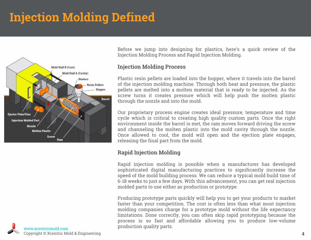
Injection Molding Process
Plastic resin pellets are loaded into the hopper, where it travels into the barrel of the injection molding machine. Through both heat and pressure, the plastic pellets are melted into a molten material that is ready to be injected. As the screw turns it creates pressure which will help push the molten plastic through the nozzle and into the mold.
Our proprietary process engine creates ideal pressure, temperature and time cycle which is critical to creating high quality custom parts. Once the right environment inside the barrel is met, the ram moves forward driving the screw and channeling the molten plastic into the mold cavity through the nozzle. Once allowed to cool, the mold will open and the ejection plate engages, releasing the final part from the mold.
Rapid Injection Molding
Rapid injection molding is possible when a manufacturer has developed sophisticated digital manufacturing practices to significantly increase the speed of the mold building process. We can reduce a typical mold build time of 6-18 weeks to just a few days. With this advancement, you can get real injectionmolded parts to use either as production or prototype.
Producing prototype parts quickly will help you to get your products to market faster than your competition. The cost is often less than what most injection molding companies charge for a prototype mold without the life expectancy limitations. Done correctly, you can often skip rapid prototyping because the process is so fast and affordable allowing you to produce low-volume production quality parts.
Injection Molding Defined
www.xcentricmold.comCopyright © Xcentric Mold & Engineering 5
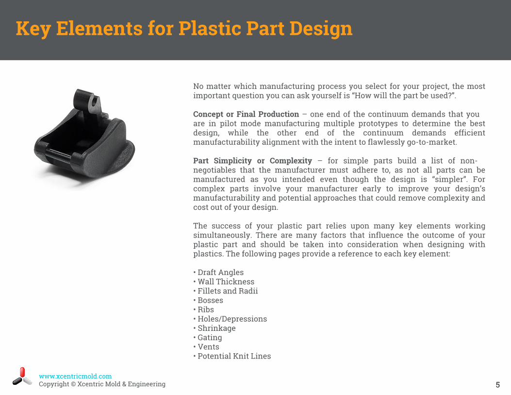
No matter which manufacturing process you select for your project, the most important question you can ask yourself is “How will the part be used?”.
Concept or Final Production – one end of the continuum demands that you are in pilot mode manufacturing multiple prototypes to determine the best design, while the other end of the continuum demands efficient manufacturability alignment with the intent to flawlessly go-to-market.
Part Simplicity or Complexity – for simple parts build a list of non-negotiables that the manufacturer must adhere to, as not all parts can be manufactured as you intended even though the design is “simpler”. For complex parts involve your manufacturer early to improve your design’s manufacturability and potential approaches that could remove complexity and cost out of your design.
The success of your plastic part relies upon many key elements working simultaneously. There are many factors that influence the outcome of your plastic part and should be taken into consideration when designing with plastics. The following pages provide a reference to each key element:
• Draft Angles• Wall Thickness• Fillets and Radii• Bosses• Ribs• Holes/Depressions• Shrinkage• Gating• Vents• Potential Knit Lines
Key Elements for Plastic Part Design
www.xcentricmold.comCopyright © Xcentric Mold & Engineering 6
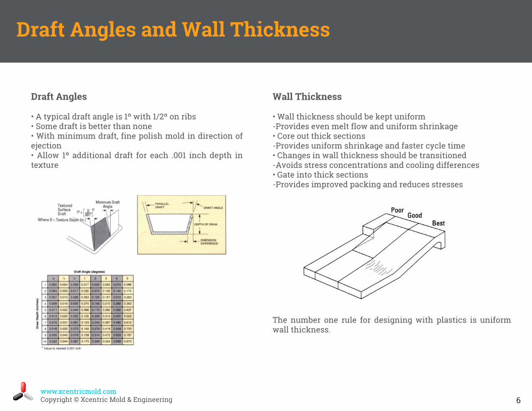
Draft Angles
• A typical draft angle is 1º with 1/2º on ribs• Some draft is better than none• With minimum draft, fine polish mold in direction ofejection• Allow 1º additional draft for each .001 inch depth intexture
Draft Angles and Wall Thickness
Wall Thickness
• Wall thickness should be kept uniform-Provides even melt flow and uniform shrinkage• Core out thick sections-Provides uniform shrinkage and faster cycle time• Changes in wall thickness should be transitioned-Avoids stress concentrations and cooling differences• Gate into thick sections-Provides improved packing and reduces stresses
The number one rule for designing with plastics is uniform wall thickness.
www.xcentricmold.comCopyright © Xcentric Mold & Engineering 7
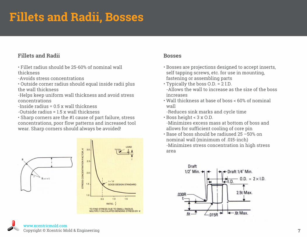
Fillets and Radii
• Fillet radius should be 25-60% of nominal wallthickness-Avoids stress concentrations• Outside corner radius should equal inside radii plusthe wall thickness-Helps keep uniform wall thickness and avoid stressconcentrations-Inside radius = 0.5 x wall thickness-Outside radius = 1.5 x wall thickness• Sharp corners are the #1 cause of part failure, stressconcentrations, poor flow patterns and increased toolwear. Sharp corners should always be avoided!
Fillets and Radii, Bosses
Bosses
• Bosses are projections designed to accept inserts,self tapping screws, etc. for use in mounting,fastening or assembling parts
• Typically the boss O.D. = 2 I.D.-Allows the wall to increase as the size of the bossincreases
• Wall thickness at base of boss < 60% of nominalwall-Reduces sink marks and cycle time
• Boss height < 3 x O.D.-Minimizes excess mass at bottom of boss andallows for sufficient cooling of core pin
• Base of boss should be radiused 25 –50% onnominal wall (minimum of .015-inch)-Minimizes stress concentration in high stressarea
www.xcentricmold.comCopyright © Xcentric Mold & Engineering 8
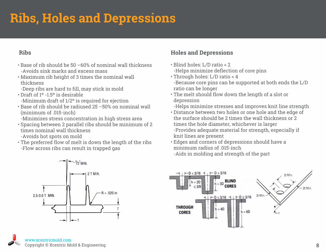
Ribs
Ribs, Holes and Depressions
Holes and Depressions
• Blind holes: L/D ratio < 2-Helps minimize deflection of core pins
• Through holes: L/D ratio < 4-Because core pins can be supported at both ends the L/Dratio can be longer
• The melt should flow down the length of a slot ordepression-Helps minimize stresses and improves knit line strength
• Distance between two holes or one hole and the edge ofthe surface should be 2 times the wall thickness or 2times the hole diameter, whichever is larger-Provides adequate material for strength, especially ifknit lines are present
• Edges and corners of depressions should have aminimum radius of .015-inch-Aids in molding and strength of the part
• Base of rib should be 50 –60% of nominal wall thickness-Avoids sink marks and excess mass
• Maximum rib height of 3 times the nominal wallthickness-Deep ribs are hard to fill, may stick in mold
• Draft of 1º -1.5º is desirable-Minimum draft of 1/2º is required for ejection
• Base of rib should be radiused 25 –50% on nominal wall(minimum of .015-inch)-Minimizes stress concentration in high stress area
• Spacing between 2 parallel ribs should be minimum of 2times nominal wall thickness-Avoids hot spots on mold
• The preferred flow of melt is down the length of the ribs-Flow across ribs can result in trapped gas
www.xcentricmold.comCopyright © Xcentric Mold & Engineering 9
Shrinkage, Gating, and Vents
Gating
• Gate thickness should be 50 –80% of the wallthickness. Gate thickness controls packing time.
• Gate width should be twice the gate thickness• Gate lands should be kept to a minimum• Gates should be located at right angles to the
runner to allow the polymer melt to impingeagainst the mold wall
• Gates should be located in thick sections of thepart
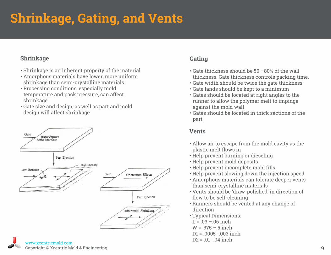
Shrinkage
• Shrinkage is an inherent property of the material• Amorphous materials have lower, more uniform
shrinkage than semi-crystalline materials• Processing conditions, especially mold
temperature and pack pressure, can affectshrinkage
• Gate size and design, as well as part and molddesign will affect shrinkage
Vents
• Allow air to escape from the mold cavity as theplastic melt flows in
• Help prevent burning or dieseling• Help prevent mold deposits• Help prevent incomplete mold fills• Help prevent slowing down the injection speed• Amorphous materials can tolerate deeper vents
than semi-crystalline materials• Vents should be ‘draw-polished’ in direction of
flow to be self-cleaning• Runners should be vented at any change of
direction• Typical Dimensions:
L = .03 –.06 inchW = .375 –.5 inchD1 = .0005 -.003 inchD2 = .01 -.04 inch

www.xcentricmold.comCopyright © Xcentric Mold & Engineering 10
Part Design Summary
• Boss height should be 2.5 times the I.D.of the boss.
• Separate the bosses from the walls inorder to maintain a uniform wall.
• The receiving hole diameter of a bossshould be equal to the self-tappingscrew pitch diameter.
• The boss O.D. should be equal to twicethe insert or screw major diameter.
• Reinforcing ribs should not be thickerthan 2/3’s the nominal wall thickness.Any thicker will create sink marks.
• The distance between two ribs shouldnot be less than two times the nominalwall.
• A strengthening gusset is typically twotimes the wall thickness deep, fourtimes the wall thickness tall, and halfthe wall thickness.
Bosses
Ribs
• Expect a flow line on a smooth surfacewhen the plastic flow came from atextured surface.
• All holes will create a weldline.• Any depression that passes 2/3’s of the
way through the wall creates aweldline.
• Irregularly shaped or square holes arenot recommended.
• The space between two holes should bethe greater of two times the wallthickness or two times the holediameter.
• Walls should have a uniform thicknessthroughout the whole design: core outthick sections.
• Must have draft –a good starting pointis at least 1 degree of draft per inch. Anydraft angle is better than no draft angle.
• Texture –add 1 degree of draft for .001inch of texture depth.
• If nominal wall thickness must change,the change should be gradual andshould not exceed 15% of the nominalwall.
Holes
Walls
• No sharp corners: radius all insideand outside corners.
• The radius of the inside corner of apart should be 50% of the nominalwall.
• The radius of an outside corner of apart should be 150% of the nominalwall.
• Radii can be as large as the designcan allow.
• Radii are impractical in certain moldlocations such as parting lines or side-cored shutoffs.
• Radius a minimum of 25% of nominalwall at the junction of walls andreinforcing ribs.
• Parts with weld lines are weaker thanparts without weld lines.
Radius
Weld Lines
www.xcentricmold.comCopyright © Xcentric Mold & Engineering 11
Webinar Series
White Paper: The Smart Guide to Designing for Manufacturability
Video Tour
About Injection Molding
Consider us for a project you are working on today. We will provide a quote within 24 hours or less.
Xcentric can provide you additional resources to increase your level of understanding of injection molding and manufacturability. Click the images to view in your browser.
Get a Quote
Additional Resources