designing of efficient fpga pipelined architecture … of efficient fpga pipelined architecture...
TRANSCRIPT
© 2015 IJEDR | Volume 3, Issue 4 | ISSN: 2321-9939
IJEDR1504016 International Journal of Engineering Development and Research (www.ijedr.org) 1
Designing of efficient fpga pipelined architecture
using spiht algorithm 1Vasundhara Malhotra ,2 Prof.Pankaj Hedao,3 Prof.Rahul Navkhare
1M.Tech Student,2Professor of Electronics and Telecommunication in Wainganga College of Engineering and Management, ,
3Professor of Electronics and Telecommunication in Wainganga College of Engineering and Management 1Department of Electronics Engineering
1Wainganga College of Engineering and Management, Nagpur, Maharashtra
________________________________________________________________________________________________________
Abstract - In this paper we present an efficient implementation of image compression of images through `Set Partitioning
in Hierarchical Trees. (SPIHT) algorithm using FPGA. Routine SPIHT is reconfigurable logic. Traditionally
computations requiring the high performance of a custom hardware implementation involved the development and
fabrication of an Application Specific Integrated Circuit (ASIC). Development of an ASIC requires several steps. The
circuit must be designed and then fabricated. SPIHT is a wavelet-based image compression coder. SPIHT is an algorithm
which basically converts the image into its wavelet transform and then transmits the information in string of embedded
coefficient. SPIHT is the method of coding and decoding the wavelet transformation of an image. By coding and
transmitting information about the discrete wavelet coefficient, it is possible for a decoder to perform an inverse
transformation on the wavelet and reconstruct the original image. The spiht algorithm can be applied to both grey scales
as well as on color images. In this paper, the error resilience and compression speed are improved. The spiht coder is a
highly improved version of L-Z algorithm and is an impactful image compression algorithm that produces an embedded
bit stream from which the best reconstructed images can be extracted at various bit rates in the sense of mean square
error. Some of the best results from SPIHT algorithm-PSNR values for given compression ratios for wide variety of
images. Hence, it has become the benchmark state of algorithm for image compression
Index Terms – Image Compression, Spiht Encoding, Decoding, Spiht algorithm, decompression Images,LIS, LSP. ________________________________________________________________________________________________________
I. INTRODUCTION
With the growth of modern technology, and the entrance into digital era, the world has found itself a huge amount of information.
Dealing with such huge information can often present hurdles. Image compression is the thing under which this kind of hurdles
can be rectified. The key component of image compression is irrelevancy and redundancy. In this paper we introduces 2-D image
using Discrete Wavelet Transform (DWT) processor for SPIHT. An effective DWT algorithm has been performed on input image
file to get the decomposed image coefficients. The Lifting Scheme reduces the number of operations execution steps to almost
one-half of those needed with a conventional convolution approach. The DWT modules were simulated using FPGA design tools.
The final design was verified with Mat lab image processing tools. Comparison of simulation results Mat lab was done to verify
the proper functionality of the developed module. The motivation in designing the hardware modules of the DWT was to reduce
its complexity, enhance its performance and to make it suitable development on are configurable FPGA based platform for VLSI
implementation. Distortion was evaluated for all images and compression rates by the Peak Signal-to-Noise Ratio (PSNR).
Architecture of Wavelet
Wavelet compression involves a way analyzing an uncompressed image in a recursive fashion, resulting in a series of higher
resolution images, each “adding to” the information content in lower resolution images. The primary steps in wavelet
compression are performing a discrete wavelet Transformation (DWT), quantization of the wavelet-space image subbands, and
then encoding these sub bands. Wavelet images by and of themselves are not compressed images; rather it is quantization and
encoding stages that do the image compression and to store the compressed image. Wavelet compression inherently results in a
set of multi-resolution images; it is well suited to working with large imagery which needs to be selectively viewed at different
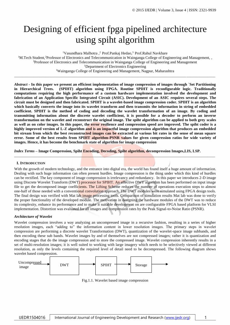
resolution, as only the levels containing the required level of detail need to be decompressed. The following diagram shows
wavelet based compression.
Uncompressed
image
Fig.1.1. Wavelet based image compression
DWT
SPIHT
Storage
© 2015 IJEDR | Volume 3, Issue 4 | ISSN: 2321-9939
IJEDR1504016 International Journal of Engineering Development and Research (www.ijedr.org) 2
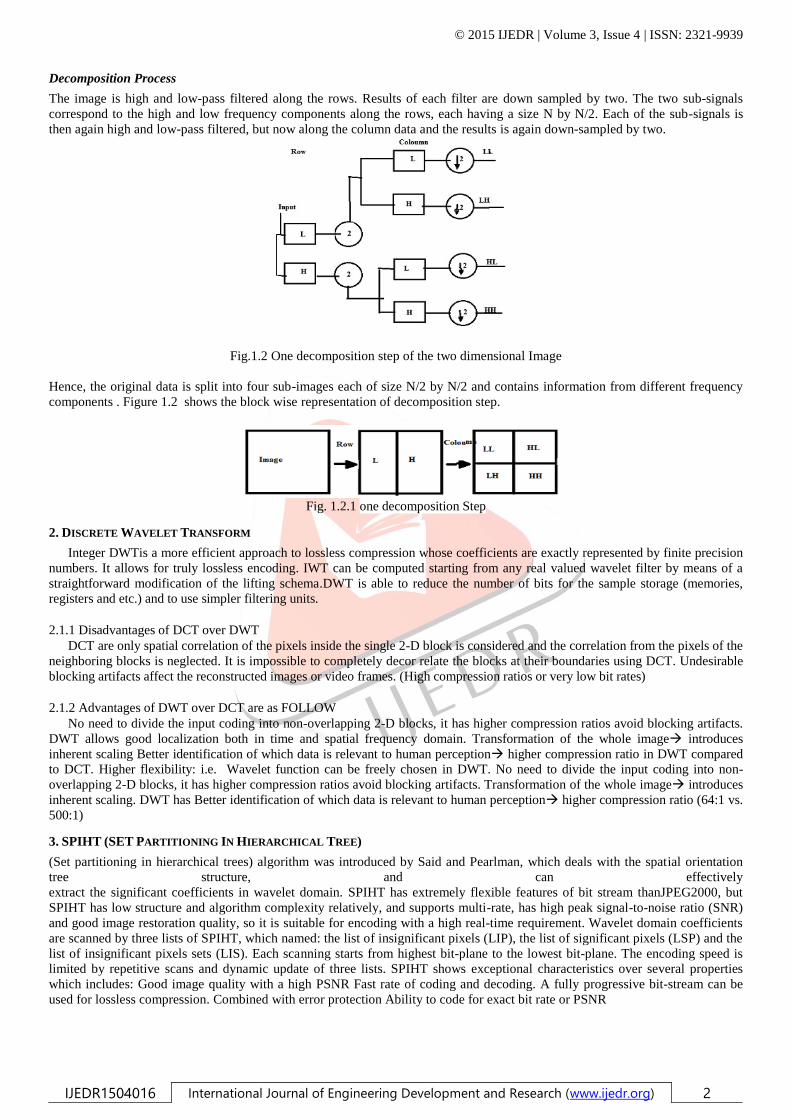
Decomposition Process
The image is high and low-pass filtered along the rows. Results of each filter are down sampled by two. The two sub-signals
correspond to the high and low frequency components along the rows, each having a size N by N/2. Each of the sub-signals is
then again high and low-pass filtered, but now along the column data and the results is again down-sampled by two.
Fig.1.2 One decomposition step of the two dimensional Image
Hence, the original data is split into four sub-images each of size N/2 by N/2 and contains information from different frequency
components . Figure 1.2 shows the block wise representation of decomposition step.
Fig. 1.2.1 one decomposition Step
2. DISCRETE WAVELET TRANSFORM
Integer DWTis a more efficient approach to lossless compression whose coefficients are exactly represented by finite precision
numbers. It allows for truly lossless encoding. IWT can be computed starting from any real valued wavelet filter by means of a
straightforward modification of the lifting schema.DWT is able to reduce the number of bits for the sample storage (memories,
registers and etc.) and to use simpler filtering units.
2.1.1 Disadvantages of DCT over DWT
DCT are only spatial correlation of the pixels inside the single 2-D block is considered and the correlation from the pixels of the
neighboring blocks is neglected. It is impossible to completely decor relate the blocks at their boundaries using DCT. Undesirable
blocking artifacts affect the reconstructed images or video frames. (High compression ratios or very low bit rates)
2.1.2 Advantages of DWT over DCT are as FOLLOW
No need to divide the input coding into non-overlapping 2-D blocks, it has higher compression ratios avoid blocking artifacts.
DWT allows good localization both in time and spatial frequency domain. Transformation of the whole image introduces
inherent scaling Better identification of which data is relevant to human perception higher compression ratio in DWT compared
to DCT. Higher flexibility: i.e. Wavelet function can be freely chosen in DWT. No need to divide the input coding into non-
overlapping 2-D blocks, it has higher compression ratios avoid blocking artifacts. Transformation of the whole image introduces
inherent scaling. DWT has Better identification of which data is relevant to human perception higher compression ratio (64:1 vs.
500:1)
3. SPIHT (SET PARTITIONING IN HIERARCHICAL TREE)
(Set partitioning in hierarchical trees) algorithm was introduced by Said and Pearlman, which deals with the spatial orientation
tree structure, and can effectively
extract the significant coefficients in wavelet domain. SPIHT has extremely flexible features of bit stream thanJPEG2000, but
SPIHT has low structure and algorithm complexity relatively, and supports multi-rate, has high peak signal-to-noise ratio (SNR)
and good image restoration quality, so it is suitable for encoding with a high real-time requirement. Wavelet domain coefficients
are scanned by three lists of SPIHT, which named: the list of insignificant pixels (LIP), the list of significant pixels (LSP) and the
list of insignificant pixels sets (LIS). Each scanning starts from highest bit-plane to the lowest bit-plane. The encoding speed is
limited by repetitive scans and dynamic update of three lists. SPIHT shows exceptional characteristics over several properties
which includes: Good image quality with a high PSNR Fast rate of coding and decoding. A fully progressive bit-stream can be
used for lossless compression. Combined with error protection Ability to code for exact bit rate or PSNR
© 2015 IJEDR | Volume 3, Issue 4 | ISSN: 2321-9939
IJEDR1504016 International Journal of Engineering Development and Research (www.ijedr.org) 3
Fig.3.1 Basic block diagram of SPIHT.
3.1.2 SPATIAL ORIENTATION TREES
Normally, most of the image’s energy is concentrated in the low frequency components. As a result, the variance decreases as one
move from the highest to the lowest of the sub band . There is a spatial self-similarity between sub bands, and the coefficients are
expected to be better magnitude-ordered as one move downward in the pyramid following the same spatial orientation. A tree
structure, called spatial orientation tree, naturally defines the spatial relationship on the hierarchical pyramid.
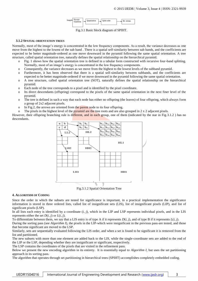
o Fig. 1 shows how the spatial orientation tree is defined in a tabular form constructed with recursive four-band splitting.
Normally, most of an image’s energy is concentrated in the low frequency components.
o Consequently, the variance decreases as we move from the highest to the lowest levels of the subband pyramid.
o Furthermore, it has been observed that there is a spatial self-similarity between subbands, and the coefficients are
expected to be better magnitude-ordered if we move downward in the pyramid following the same spatial orientation.
o A tree structure, called spatial orientation tree (SOT), naturally defines the spatial relationship on the hierarchical
pyramid.
o Each node of the tree corresponds to a pixel and is identified by the pixel coordinate.
o Its direct descendants (offspring) correspond to the pixels of the same spatial orientation in the next finer level of the
pyramid.
o The tree is defined in such a way that each node has either no offspring (the leaves) of four offspring, which always form
a group of 2x2 adjacent pixels.
o In Fig.2, the arrows are oriented from the parent node to its four offspring.
o The pixels in the highest level of the pyramid are the tree roots and are also grouped in 2 x 2 adjacent pixels.
However, their offspring branching rule is different, and in each group, one of them (indicated by the star in Fig.3.1.2 ) has no
descendants.
Fig.3.1.2 Spatial Orientation Tree
4. ALGORITHM OF CODING
Since the order in which the subsets are tested for significance is important, in a practical implementation the significance
information is stored in three ordered lists, called list of insignificant sets (LIS), list of insignificant pixels (LIP), and list of
significant pixels (LSP).
In all lists each entry is identified by a coordinate (i, j), which in the LIP and LSP represents individual pixels, and in the LIS
represents either the set D(i, j) or L(i, j).
To differentiate between them, we say that a LIS entry is of type A if it represents D(i, j), and of type B if it represents L(i, j).
During the sorting pass (see Algorithm I), the pixels in the LIP-which were insignificant in the previous pass-are tested, and those
that become significant are moved to the LSP.
Similarly, sets are sequentially evaluated following the LIS order, and when a set is found to be significant it is removed from the
list and partitioned.
The new subsets with more than one element are added back to the LIS, while the single-coordinate sets are added to the end of
the LIP or the LSP, depending whether they are insignificant or significant, respectively.
The LSP contains the coordinates of the pixels that are visited in the refinement pass.
Below we present the new encoding algorithm in its entirety. It is essentially equal to Algorithm I, but uses the set partitioning
approach in its sorting pass.
The algorithm that operates through set partitioning in hierarchical trees (SPIHT) accomplishes completely embedded coding.
© 2015 IJEDR | Volume 3, Issue 4 | ISSN: 2321-9939
IJEDR1504016 International Journal of Engineering Development and Research (www.ijedr.org) 4
This SPIHT algorithm uses the principles of partial ordering by magnitude, set partitioning by significance of magnitudes with
respect to a sequence of octavely decreasing thresholds, ordered bit plane transmission, and self-similarity across scale in an
image wavelet transform.
The realization of these principles in matched coding and decoding algorithms is more effective than the implementations of
EZW coding.
The results of this coding algorithm with its embedded code and fast execution are so impressive that it is a serious candidate for
standardization in future image compression system
Process LIS
for each set (i,j) in LIS
if type D
Send Sn(D(i,j))
If Sn(D(i,j))=1
for each (k,l)∈ O(i,j)
outputSn(k,l)
ifSn(k,l)=1, then add (k,l) to the LSP and output sign of coeff: 0/1 = -/+
ifSn(k,l)=0, then add (k,l) to the end of the LIP
endfor
endif
else (type L )
Send Sn(L(i,j))
If Sn(L(i,j))=1
add each (k,l) ∈O(i,j) to the end of the LIS as an entry of type D
remove (i,j) from the LIS
end if on type
End loop over LIS
Refinement Pass
Process LSP
for each element (i,j) in LSP – except those just added above
Output the nth most significant bit of coeff
End loop over LSP
Update
Decrement n by 1
Go to Significance Map Encoding Step
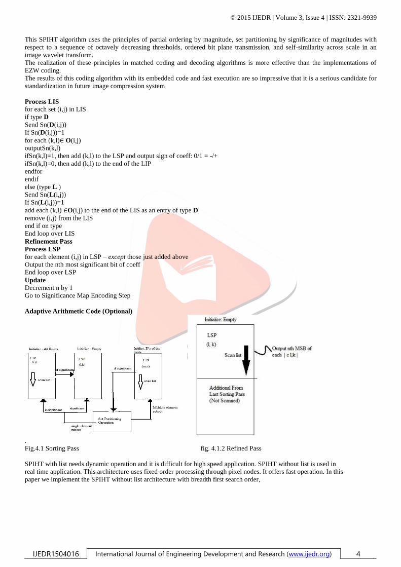
Adaptive Arithmetic Code (Optional)
.
Fig.4.1 Sorting Pass fig. 4.1.2 Refined Pass
SPIHT with list needs dynamic operation and it is difficult for high speed application. SPIHT without list is used in
real time application. This architecture uses fixed order processing through pixel nodes. It offers fast operation. In this
paper we implement the SPIHT without list architecture with breadth first search order,

© 2015 IJEDR | Volume 3, Issue 4 | ISSN: 2321-9939
IJEDR1504016 International Journal of Engineering Development and Research (www.ijedr.org) 5
Fig.4.1.3 Image compression Block Diagram of Set Partitioning in Hierarchical Tree.
5 TERMS USED IN IMAGE COMPRESSION
There are various types of terms that are used in calculation of image compression. Some are
Listed below:
5.1.1 Peak signal to noise ratio
The phrase peak signal-to-noise ratio, often abbreviated PSNR, is an engineering term for the ratio between the maximum
possible power of a signal and the power of corrupting noise that affects the fidelity of its representation .Because many signals
have a very wide dynamic range, PSNR is usually expressed in terms of the logarithmic decibel scale.
The PSNR is most commonly used as a measure of quality of reconstruction in image compression etc. It is most easily defined
via the mean squared error (MSE) which for two m×n monochrome images I and K where one of the images is considered a noisy
approximation of the other is defined as:
The PSNR is defined as:
Here, Max is the maximum possible pixel value of the image. When the pixels are represented using 8 bits per sample, this is
255. More generally, when samples are represented using linear PCM with B bits per sample, MAXI is 2B-1.For color images with
three RGB values per pixel, the definition of PSNR is the same except the MSE is the sum over all squared value differences
divided by image size and by three. An identical image to the original will yield an undefined PSNR as the MSE will become equal
to zero due to no error. In this case the PSNR value can be thought of as approaching infinity as the MSE approaches zero; this
shows that a higher PSNR value provides a higher image quality. At the other end of the scale an image that comes out with all zero
value pixels (black) compared to an original does not provide a PSNR of zero. This can be seen by observing the form, once again,
of the MSE equation. Not all the original values will be a long distance from the zero value thus the PSNR of the image with all
pixels at a value of zero is not the worst possible case.
5.1.2 Signal-to-noise ratio
It is an electrical engineering concept, also used in other fields (such as scientific measurements, biological cell signaling),
defined as the ratio of a signal power to the noise power corrupting the signal. In less technical terms, signal-to-noise ratio
compares the level of a desired signal (such as music) to the level of background noise. The higher the ratio, the less obtrusive the
background noise is. In engineering, signal-to-noise ratio is a term for the power ratio between a signal (meaningful information)
and the background noise:
.
Where P is average power and A is RMS amplitude. Both signal and noise power (or amplitude) must be measured at the same
or equivalent points in a system, and within the same system bandwidth. Because many signals have a very wide dynamic range,
SNRs are usually expressed in terms of the logarithmic decibel scale. In decibels, the SNR is, by definition, 10 times the logarithm
of the power ratio. If the signal and the noise is measured across the same impedance then the SNR can be obtained by calculating
20 times the base-10 logarithm of the amplitude ratio:
© 2015 IJEDR | Volume 3, Issue 4 | ISSN: 2321-9939
IJEDR1504016 International Journal of Engineering Development and Research (www.ijedr.org) 6
In image processing, the SNR of an image is usually defined as the ratio of the mean pixel value to the standard deviation of the
pixel values. Related measures are the "contrast ratio “and the "contrast-to-noise ratio". The connection between optical power and
voltage in an imaging system is linear. This usually means that the SNR of the electrical signal is calculated by the 10 log rule.
With an interferometer system, however, where interest lies in the signal from one arm only, the field of the electromagnetic wave
is proportional to the voltage (assuming that the intensity in the second, the reference arm in constant). Therefore the optical power
of the measurement arm is directly proportional to the electrical power and electrical signals from optical interferometer are
following the 20 log rule. The Rose criterion (named after Albert Rose) states that an SNR of at least 5 is needed to be able to
distinguish image features at 100% certainty. An SNR less than 5 means less than 100% certainty in identifying image details.
5.1.3 Mean Square Error
In statistics, the mean square error or MSE of an estimator is one of many ways to quantify the amount by which an estimator
differs from the true value of the quantity being estimated. As a loss function, MSE is called squared error loss. MSE measures the
average of the square of the "error". The error is the amount by which the estimator differs from the quantity to be estimated. The
difference occurs because of randomness or because the estimator doesn't account for information that could produce a more
accurate estimate. The MSE is the second moment (about the origin) of the error, and thus incorporates both the variance of the
estimator and its bias. For an unbiased estimator, the MSE is the variance. Like the variance, MSE has the same unit of
measurement as the square of the quantity being estimated. In an analogy to standard deviation, taking the square root of MSE
yields the root mean square error or RMSE, which has the same units as the quantity being estimated; for an unbiased estimator, the
RMSE is the square root of the variance, known as the standard error.
6 SIMULATIONS AND RESULTS
Image compression is the process of encoding information using fewer bits (or other information-bearing units) than any
encoded representation would use, through use of specific encoding schemes. Image compression is minimizing the size in bytes of
a graphics file without degrading the quality of the image to an unacceptable level. The reduction in file size allows more images to
be stored in a given amount of disk or memory space. It also reduces the time required for images to be sent over the Internet or
downloaded from WebPages.
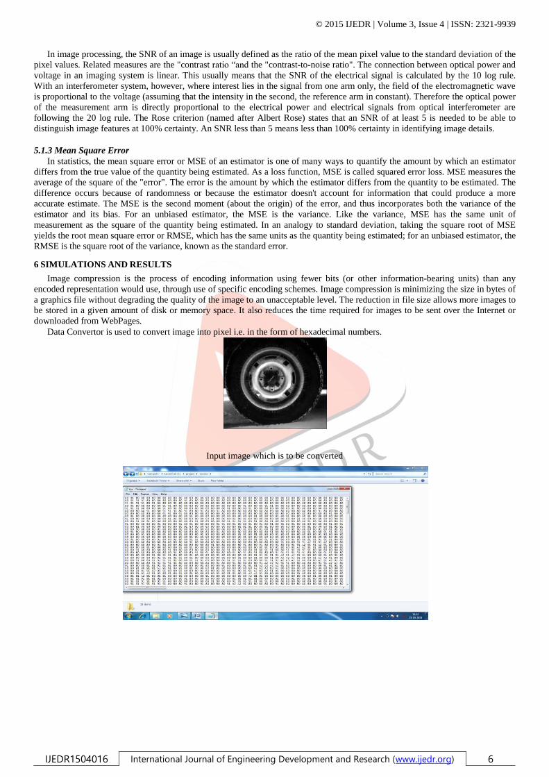
Data Convertor is used to convert image into pixel i.e. in the form of hexadecimal numbers.
Input image which is to be converted

© 2015 IJEDR | Volume 3, Issue 4 | ISSN: 2321-9939
IJEDR1504016 International Journal of Engineering Development and Research (www.ijedr.org) 7
Result data after Compression of Image
Schematic Diagram of SPIHT
RTL layout of SPIHT

© 2015 IJEDR | Volume 3, Issue 4 | ISSN: 2321-9939
IJEDR1504016 International Journal of Engineering Development and Research (www.ijedr.org) 8
Behavioral structure of decompression image
Design Summary
Figure1 Figure 2
Calculated Parameters using Matlab2010b
CR = 1.3333
MSE = 310.6245
PSNR = 17.2218
CONCLUSION
SPIHT has many advantages, such as good image quality, high PSNR and good progressive image transmission. Hence, it also has
wider application in the compression of images. Atypical successful example was that an improvement to SPIHT has to be used to
compress the images. Although the improvement made the memory space requirement to be optimized by some additional means,
The PSNR of compressed image can improved to much more extent compared to image compressed through the SPIHT method. At

© 2015 IJEDR | Volume 3, Issue 4 | ISSN: 2321-9939
IJEDR1504016 International Journal of Engineering Development and Research (www.ijedr.org) 9
lower bit rates, the PSNR is almost identical for the original and modified versions but at higher bit rates, the PSNR is higher for
the modified algorithm than the original one.
REFERENCES
[1] Hualiang Zhu, ChundiXiu and Dongkai Yang “ An Improved SPIHT Algorithm Basedon Wavelet Coefficient Blocks for Image
Coding ” Beijing University of Aeronautics andAstronautics Beijing, P.R.China
[3] ASaid and W.APeariman, "A new fast and efficient image codec based on set partitioningin hierarchical trees," IEEE Trans.
Circuits and Systems for Video Technology, vol. 6, no.3,pp.243-250, Jun.1996.
[4] A. Said,and W. A. Pearlman, “ A new, fast and efficient image code based on setpartitioning in hierarchical trees”, IEEE
Transactions on Circuits and Systems for Video technology, 1996, 6(6):243-250.
[5] J. H. Zhao, W. J. Sun, Z. Meng, Z. H. Hao, “Wavelet transform characteristics andcompression coding of remote sensing
images,” Optics and Precision Engineering, vol. 12(2),pp.205-210, 2004.
[6] H. L. Xu, S. H. Zhong, “Image Compression Algorithm of SPIHT Based on Block-Tree,”Journal of Hunan Institute of
Engineering, vol. 19(1), pp.58-61, 2009.
[7] B. Yan, H. Zhang, “SPIHT Algorithm and its Improvement,” Computer Applications andSoftware, vol. 25(8), pp.245-247,
2008.
[8] F. W. Wheeler, and W. A. Pearlman, “SPIHT Image Compression without Lists,” IEEEInt. Conf on Acoustics, Speech and
Signal Processing(ICASSP 2000). Istanbul: IEEE,2000.2047-2050.
[9] Jianxiong Wang “Study of the Image Compression based on SPIHT Algorithm” collegeof water resources & hydropower and
architecture, yunnan agriculture university Kunming.
[10] Min HU, ChangjiangZhang , Juan LU, Bo Zhou “A Multi-ROIs Medical ImageCompression Algorithm with Edge Feature
Preserving” Zhejiang normal university.
[11] JiaZhiGangGuoXiaoDong Li LinSheng “A Fast Image Compression Algorithm Basedon SPIHT ” College of Electronic and
Information Engineering TaiYuan University ofScience and Technology TaiYuan, ShanXi, China.
[12] Jianjun Wang “Modified SPIHT Based Image Compression Algorithm for HardwareImplementation” Xi’an Institute of Optics
and Precision Mechanics Chinese Academy ofSciences Xi’an.
[13] LIU Wei “Research on Image Compression Algorithm Based on SPHIT” School ofEquipment and Engineering
ShenYangLigong University Shenyang, P.R.China.
[14] Chunlei Jiang “A Hybrid Image Compression Algorithm Based on Human VisualSystem” Electrical and Information
Engineering College Northeast Petroleum UniversityDaqing, Heilongjiang Province.
[15] J. Jyotheswar, SudiptaMahapatra “Efficient FPGA implementation of DWT andmodified SPIHT for lossless image
compression” Department of Electronics and ElectricalCommunication Engineering, IIT Kharagpur, Kharagpur 721 302, West
Bengal Nov. 2006.
[16] Macarena Boix ,BegoñaCantó “Wavelet Transform application to the compression ofimages” a Departamento de
MatemáticaAplicada, Universidad Politécnica de Valencia,EscuelaPolitécnica Superior de Alcoy, Plaza Ferrándiz y Carbonell 2,
03801 Alcoy(Alicante), Spain b Instituto de MatemáticaMultidisciplinar, Universidad Politécnica deValencia, 46022 Valencia,
Spain.
[17] Stephan Rein , Martin Reisslein,” Performance evaluation of the fractional wavelet filter:A low-memory image wavelet
transform for multimedia sensor networks” aTelecommunication Networks Group, Technical University Berlin, Berlin b School
ofElectrical, Computer, and Energy Eng., Goldwater Center, MC 5706, Arizona StateUniversity, Tempe, AZ 85287-5706, United
States.
[18] J. Jyotheswar, SudiptaMahapatra “Efficient FPGA implementation of DWT andmodified SPIHT for lossless image
compression” Department of Electronics and ElectricalCommunication Engineering, IIT Kharagpur, Kharagpur 721 302, West
Bengal, India.
[19] Peter Schelkens, Adrian Munteanu, Jan Cornelis “Wavelet-based compression ofmedical images: Protocols to improve
resolution and quality scalability and region-of-interestcoding” Department of Electronics and Information Processing (ETRO),
VrijeUniversiteitBrussel, Pleinlaan.
[20] Jose Oliver “A Fast Run-Length Algorithm for Wavelet Image Coding with ReducedMemory Usage” M.P. Malumbres
Department of Computer Engineering (DISCA), TechnicalUniversity of Valencia Camino de Vera 17, 46017, Spain.
[21] Pasquale Corsonello, StefaniaPerrib, Paolo Zicari, Giuseppe Cocorullo“Microprocessor-based FPGA implementation of
SPIHT image compression subsystems” aDepartment of Computer Science, Mathematics, Electronics and Transportation
University ofReggio Calabria, Loc. Feo di Vito, 89060 Reggio Calabria, Italy Department of Electronics,Computer Science and
Systems University of Calabria, Arcavacata di Rende