designing spacecraft and mission operations plans to … spacecraft and mission operations plans to...
TRANSCRIPT

Designing Spacecraft and Mission Operations
Plans to Meet Flight Crew Radiation Dose
Requirements:
Why is this an “Epic Challenge” for Long-Term Manned
Interplanetary Flight
(Hint – It’s About the Money)
NASA/MIT Workshop
06/26/12 NASA/JSC/ES4/Steve Koontz
https://ntrs.nasa.gov/search.jsp?R=20120012405 2018-06-06T02:44:30+00:00Z
I-2 I-2
2
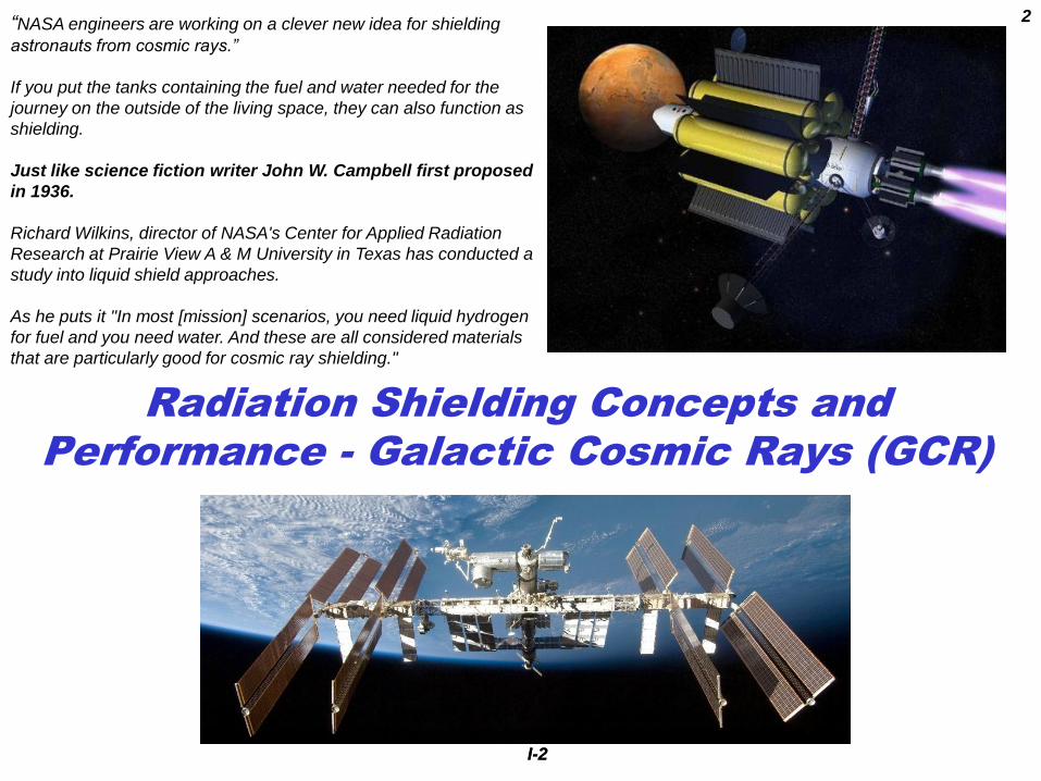
Radiation Shielding Concepts and
Performance - Galactic Cosmic Rays (GCR)
“NASA engineers are working on a clever new idea for shielding
astronauts from cosmic rays.”
If you put the tanks containing the fuel and water needed for the
journey on the outside of the living space, they can also function as
shielding.
Just like science fiction writer John W. Campbell first proposed
in 1936.
Richard Wilkins, director of NASA's Center for Applied Radiation
Research at Prairie View A & M University in Texas has conducted a
study into liquid shield approaches.
As he puts it "In most [mission] scenarios, you need liquid hydrogen
for fuel and you need water. And these are all considered materials
that are particularly good for cosmic ray shielding."

Presentation Outline
Radiation Shielding Concepts and Performance – Galactic Cosmic Rays (GCRs)
Some general considerations
Galactic Cosmic Rays
GCR Shielding I: What material should I use and how much do I need?
GCR shielding materials design and verification
Spacecraft materials point dose cosmic ray shielding performance – hydrogen content and
atomic number
Accelerator point dose materials testing
Material ranking and selection guidelines
Development directions and return on investment (point dose metric)
Secondary particle showers in the human body
limited return of investment for low-Z, high–hydrogen content materials
GCR shielding II: How much will it cost?
Spacecraft design and verification for mission radiation dose to the crew
Habitat volume, shielding areal density, total weight, and launch cost for two habitat
volumes
It’s All about the Money - Historical NASA budgets and budget limits
So, what can I do about all this?
Program Design Architecture Trade Space
The Vehicle Design Trade Space
Some Near Term Recommendations
The Epic Challenges
Supporting Materials
I-3
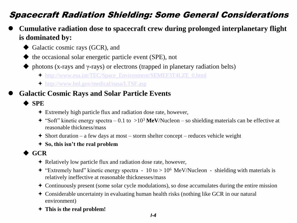
Spacecraft Radiation Shielding: Some General Considerations
Cumulative radiation dose to spacecraft crew during prolonged interplanetary flight
is dominated by:
Galactic cosmic rays (GCR), and
the occasional solar energetic particle event (SPE), not
photons (x-rays and γ-rays) or electrons (trapped in planetary radiation belts)
http://www.esa.int/TEC/Space_Environment/SEMEF3T4LZE_0.html
http://www.bnl.gov/medical/nasa/LTSF.asp
Galactic Cosmic Rays and Solar Particle Events
SPE
Extremely high particle flux and radiation dose rate, however,
“Soft” kinetic energy spectra – 0.1 to >103 MeV/Nucleon – so shielding materials can be effective at
reasonable thickness/mass
Short duration – a few days at most – storm shelter concept – reduces vehicle weight
So, this isn’t the real problem
GCR
Relatively low particle flux and radiation dose rate, however,
“Extremely hard” kinetic energy spectra - 10 to > 106 MeV/Nucleon - shielding with materials is
relatively ineffective at reasonable thicknesses/mass
Continuously present (some solar cycle modulations), so dose accumulates during the entire mission
Considerable uncertainty in evaluating human health risks (nothing like GCR in our natural
environment)
This is the real problem!
I-4

I-5
Galactic Cosmic Rays
I-5
Geomagnetic Shielding Effects
http://www.fluka.org/content/publications/1998_bologna.pdf

I-6
Galactic
Cosmic Rays
I-6
6
Galactic Cosmic Ray Environment “in a nutshell”
http://www.srl.caltech.edu/personnel/d
ick/cos_encyc.html
1 10 1001 10
6
1 104
0.01
1
100
1 104
1 106
1 108
intflxZi
annintflxZi
zi
annintflxZi
81.466·10
71.383·10
53.588·10
53.683·10
47.232·10
45.177·10
43.802·10
33.474
GCR Nucleus
H
He
C
O
Mg
Si
Fe
Zn
zi
1
2
6
8
12
14
26
30
Interplanetary cosmic ray surface flux at 1 AU: NRL/Vanderbilt CREME-96 solar minimum (worst-case) GCR model -
https://creme-mc.isde.vanderbilt.edu/
http://pdg.lbl.gov/2010/reviews/rpp2010-
rev-cosmic-rays.pdf
intflxZ = #/(cm2 sec)
annintflxZ = #/(cm2 year)

I-7 7
Susan Bailey, “Air Crew Radiation Exposure and
Overview,” Nuclear News, pp 32-40, January 2000
http://www.ans.org/pubs/magazines/nn/docs/2000-1-3.pdf Image Credit -The Boeing Company
GCR Earth Surface and Atmospheric Environments: Dominated by GCR secondary
particle air showers Earth surface/atmospheric environments
• 1000 grams/cm2 air shielding mass at sea level
• latitude dependent geomagnetic shielding
• GCR secondary particle shower products dominate
• GCR contributes about 10% of annual background
dose
Commercial and military aviation environments
• Altitude dependent air shielding mass
• Latitude dependent geomagnetic shielding
• Solar cycle modulation of GCR environment
• Latitude dependent solar particle event exposure
• Pfotzer secondary shower particle maximum at
about 20 km altitude (mid latitudes)
• Average ISS hourly crew dose rates are on the order
of 20µSv/hr - comparable to commercial aircraft
dose rates on polar routes at solar minimum

8
1.2: GCR Exposure Environments:
Low Earth Orbit (LEO) – Primary
CR and secondary particle showers
LET (MeV cm2/mg) Si
1 103
0.01 0.1 1 10 100
1 103
0.01
0.1
1
10
100
1 103
1 104
1 105
1 106
1 107
1 108
1 109
1 1010
1 1011
SiDet1
SiDet2
SiDet3
SiDet4
SiDet5
SiDet6
SiDet7
SiDet8
LETmeanBIN( )
ISS Orbit Environment Combined ISS GCR and
trapped proton environments
with secondary particle showers
Steve Koontz, Brandon Reddell,
Paul Boeder: “Calculating
Spacecraft single Event
Environments with FLUKA, Paper
W-33, Proceedings of the 2011
NSREC Radiation Effects Data
Workshop, IEEE, July 2011
FLUKA (FLUktuierende
Kaskade) differential LET
Spectra at different shielding
masses
The differential LET spectra [#/(cm2
week LET)] at various shielding depths
in a concentric spherical shell model
spacecraft is shown to the right.
LET spectra are calculated, using the
FLUKA (1) Monte Carlo radiation
transport code, as the number of
particles entering each of the Si detector
shells placed at various depths in the
concentric spherical shell model (see the
table below).
All secondary particle shower processes
are enabled and full shielding mass
distribution function for each Si shell is
utilized in a fully three dimensional
calculation. Total ionizing dose and
nuclear reactions “star” density is also
calculated but not reported here.
Detector Si Shell SiDet1 SiDet2 SiDet3 SiDet4 SiDet5 SiDet6 SiDet7 SiDet8
Detector Shell Radius (cm) 5037.4 5037.3 5037.1 5035.6 5033.7 5030.0 5018.9 5000.0
Si Detector Median Al Shielding Mass in g/cm2
0.15 0.81 1.6 7.9 15.6 31.1 77.5 156.2

9
1 103
0.01 0.1 1 10 100
1 103
0.01
0.1
1
10
100
1 103
1 104
1 105
1 106
1 107
1 108
1 109
1 1010
1 1011
SiDet1
SiDet2
SiDet3
SiDet4
SiDet5
SiDet6
SiDet7
SiDet8
LETmeanBIN( )
Interplanetary Environment Interplanetary GCR environment
with secondary particle showers
LET (MeV cm2/mg) Si
1.3 GCR Exposure Environments:
Interplanetary Environment –
Primary CR and secondary
particle showers
Steve Koontz, Brandon Reddell,
Paul Boeder: “Calculating
Spacecraft single Event
Environments with FLUKA,
Paper W-33, Proceedings of the
2011 NSREC Radiation Effects
Data Workshop, IEEE, July 2011
FLUKA (FLUktuierende
Kaskade) differential LET
Spectra at different shielding
masses
Detector Si Shell SiDet1 SiDet2 SiDet3 SiDet4 SiDet5 SiDet6 SiDet7 SiDet8
Detector Shell Radius (cm) 5037.4 5037.3 5037.1 5035.6 5033.7 5030.0 5018.9 5000.0
Si Detector Median Al Shielding Mass in g/cm2
0.15 0.81 1.6 7.9 15.6 31.1 77.5 156.2
The differential LET spectra [#/(cm2
week LET)] at various shielding depths
in a concentric spherical shell model
spacecraft is shown to the right.
LET spectra are calculated, using the
FLUKA (1) Monte Carlo radiation
transport code, as the number of
particles entering each of the Si detector
shells placed at various depths in the
concentric spherical shell model (see the
table below).
All secondary particle shower processes
are enabled and the full shielding mass
distribution function for each Si shell is
utilized in a fully three dimensional
calculation. Total ionizing dose and
nuclear reactions “star” density is also
calculated but not reported here.

FLUKA: Solar Particle Events – Dose, Depth, Shielding Material
I-10
1 10 1000.01
0.1
1
10
100
1 103
1 104
Dosej00bndAlj
Dosej00bndCj
Dosej00bndPEj
Dosej00bndTij
Alshldj Cshldj PEshldj Tishldj
1 10 1000.1
1
10
100
1 103
1 104
Doseo03bndAlj
Doseo03bndCj
Doseo03bndPEj
Doseo03bndTij
Alshldj Cshldj PEshldj Tishldj
July 2000 SPE,; Dose in cGy October 2003 SPE; Dose in cGy
Maximum quiescent
GCR daily
background
Maximum
quiescent GCR
daily background
Steve Koontz, William Atwell, Brandon Reddell, Kristina Rojdev; NASA TP-2010-216133

GCR SHIELDING I: WHAT
MATERIAL SHOULD I USE
AND HOW MUCH DO I NEED?
I-11
Spacecraft GCR Shielding Materials
Point dose calculations and complimentary accelerator testing suggest that low-Z,
high- hydrogen content materials may provide acceptable crew shielding against
GCR during long duration interplanetary missions with reasonable shielding mass
Unfortunately point dose calculations and measurements do not take into account
the fact that the human body is an extended target capable of producing internal
secondary particle showers
See charts 16 and 17
Compare to charts 13, 14, and 15
Over the range of shielding masses considered to date (10 to 120 g/cm2) the
benefits of low-Z, high-hydrogen content materials are small when secondary
particle showers inside the human body are taken into account.
Liquid hydrogen is the only substance that continues to show significant benefits
A number of unsolved problems prevent the use liquid hydrogen as a GCR shielding
material, e.g. a boiling point of 21 degrees K
GCR shielding performance depends primarily on atomic number, hydrogen
content, and areal density. The state of chemical combination of the elements in a
material has little or no effect on GCR shielding performance
I-12

I-13
Spacecraft Materials Point Dose Cosmic Ray Shielding
Performance – Hydrogen Content and Atomic Number
13
http://srag.jsc.nasa.gov/Publication
s/TM104782/techmemo.htm
J. W. Wilson, J. Miller, A. Konradi,,and F. A. Cucinotta;
Shielding Strategies for Human Space Exploration, , NASA Conference
Publication 3360December 1997
Janet Barzilla, 6/24/2012
New Design Objective - 150 mSv total career
equivalent dose
Historical
annual limit –
500 mSv/y to
BFO;
Note that liquid hydrogen isn’t a simple
shielding material. It is a shielding system
because maintaining a cryogenic liquid
adjacent to a manned crew cabin for several years
implies liquid containment and an as yet TBD
thermal control system, neither of which will
be weightless

I-14
14
C. Zeitlin, S. Guetersloh, L .Heilbronn , J. Miller, N. Elkhayari, A.Empl, M. LeBourgeois, B.
W. Mayes, L. Pinsky, M .Christl, and E. Kuznetsov; “Shielding experiments with high-
energy heavy ions for spaceflight applications,” New J. Phys. 10 (2008) 075007
doi:10.1088/1367-2630/10/7/075007
Zeitlin, Cary, Guetersloh, Stephen B., Heilbronn,
Lawrence H.Miller, Jack ;, “Measurements of
Materials Shielding Properties with 1 GeV/nuc
56Fe;http://escholarship.org/uc/item/6xh1d1pk
δDn= normalized dose reduction, with units of (g cm-2)-1.
1 GeV/nuc 56Fe on Various Targets
δD(0) = δDn at
zero target depth
Accelerator point dose testing

I-15
Development Directions and
Return on Investment (point dose metric)
Replacing structural aluminum with
low Z, H-rich composites
Strength to weight ratio better than
aerospace aluminum (to reduce weight)
No toxicity or flammability issues
Structural margins and reliability
comparable to aerospace aluminum
Understand and control defect
driven structural failures
Avoid the fate of the Boeing 787
Making hydrogen usable as shielding
Reliable containment in nano-structured
materials
Defeat natural limits imposed by
chemical bonding and valance
Guaranteed hydrogen containment
in all space flight environments
Radiation damage of containment
cannot release hydrogen
Guaranteed control of flammability
and explosion hazards
15
R.K. Tripathi, “Space Exploration: Where we
have been, Where we are and Where we are
going – a human perspective,” 29th
International Cosmic Ray Conference Pune
(2005) 2, 437-440
The return on investment
appears to be enormous,
but isn’t!

I-16
(Cucinotta, Space Radiation Cancer Risk Projections and uncertainties 2010)
• However, secondary particle showers
inside the human body itself can make
important contributions to equivalent
dose.
• The apparent advantages of low-Z,
hydrogen-rich materials much less
pronounced than indicated by a point
dose comparison.
• Note that the shielding performance
data on charts 13-15 represent point
dose estimates only, not whole body
estimates including in-body particle
showers.
• Compare the graph to the right with
those on charts 13-15.
• Interesting to note that nothing
useful happens between 20 and 120
g/cm2 for Al or PE, and E > 150mSv/y

I-17
Cucinotta, F., Kim, M. Y., Ren, L.; “Evaluating shielding
effectiveness for reducing space radiation cancer risks,”
Radiation Measurements 41 (2006) 1173 – 1185
Fig. 4 Point dose equivalent (upper panel) and effective dose
(bottom panel) behind various shields for solar minimum GCR
and August 1972 SPE (the units for the SPE doses are for total
event and not necessarily per year).
150 mSv/yr
150 mSv/yr

GCR SHIELDING II: HOW
MUCH WILL IT COST?
I-18

Spacecraft design and verification for mission radiation dose to crew:
Program specific crew dose design objectives or not-to-exceed limits defined as whole
body Equivalent dose some other calculable and measurable dose metric
Current Baseline E = 150mSv/yr ; and E= 150mSv Career
GCR and SPE Environments definition and models for design and verification
Example: The JSC Badhwar/O’Neill GCR environment model including solar cycle modulation
Example: The Moscow State University GCR environment model (as currently implemented in the
CREME 96 radiation effects on microelectronics code https://creme.isde.vanderbilt.edu/)
A worst-case solar particle event environment . For example, see Steve Koontz, William Atwell,
Brandon Reddell, Kristina Rojdev; NASA TP-2010-216133
Numerical descriptions of the spacecraft structure and materials – essentially a CAD
model of some type that describes the three dimensional structure and composition of the
spacecraft
A nuclear reaction and transport code that can calculate the equivalent dose at various
locations in the spacecraft by:
Effectively applying the GCR or SEP design environment to the exterior of the spacecraft as an
isotropic particle flux
Simulating particle reaction and transport through the spacecraft materials and
Calculating the required crew dose metric at several selected location in the habitable volume
Semi-empirical deterministic codes include CREME-96 and HZETRN – less accurate and complete but
short run times even on a PC.
Physics based Monte-Carlo codes such as FLUKA – complete physics and more accurate in principle
but very long run times or large cluster computing systems
Monte Carlo codes are often used to support development and verification of semi-empirical
deterministic codes I-19

WHAT IS THE WEIGHT OF THE SHIELDING MASS NEEDED TO COMPLETELY
ENCLOSE A CYLINDRICAL HABITAT AT DIFFERENT AREAL DENSITIES
BETWEEN 10 G/CM2 AND 1000 G/CM2?
HOW MUCH DOES IT COST TO LAUNCH THAT WEIGHT TO LEO?
THE ESTIMATE INCLUDES BASELINE VEHICLE AND ANY SUPPLEMENTARY
SHIELDING MASS
1) A CYLINDER 20 METERS LONG AND 10 METERS IN DIAMETER (785 M2; 1.6
X 103 M3)
2) A CYLINDER 7 METERS LONG AND 5 METERS IN DIAMETER (A = 149 M2;
V = 137 M3)
I-20
I-21
21
Shielding Areal
Density (g/cm2)
Total
Shielding
mass (kg)
Shielding launch cost
(@ $50,000/kg to LEO)
Shielding launch cost
(@ $5,000/kg to LEO)
1000 7.9 x10⁶ $3.93 x10¹¹ $3.93 x10¹⁰
500 3.9 x10⁶ $1.96 x10¹¹ $1.96 x10¹⁰
100 7.9 x10⁵ $ 3.93 x10¹⁰ $3.93 x10⁹
50 3.9 x10⁵ $1.96 x10¹⁰ $1.96 x10⁹
10 7.9 x10⁴ $3.93 x10⁹ $3.93 x10⁸
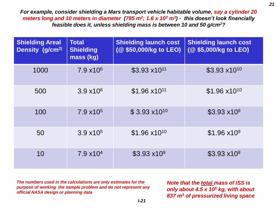
For example, consider shielding a Mars transport vehicle habitable volume, say a cylinder 20
meters long and 10 meters in diameter (785 m2; 1.6 x 10³ m3) - this doesn’t look financially
feasible does it, unless shielding mass is between 10 and 50 g/cm2?
Note that the total mass of ISS is
only about 4.5 x 10⁵ kg, with about
837 m3 of pressurized living space
The numbers used in the calculations are only estimates for the
purpose of working the sample problem and do not represent any
official NASA design or planning data

I-22 I-22
Shielding Areal
Density (g/cm2)
Total
Shielding
mass (kg)
Shielding launch cost
(@ $50,000/kg to LEO)
Shielding launch cost
(@ $5,000/kg to LEO)
1000 1.49 x 10⁶ $7.5 x10¹⁰ $7.5 x10⁹
500 7.5 x10⁵ $3.7 x10¹⁰ $3.7 x10⁹
100 1.5 x10⁵ $7.5 x10⁹ $7.5 x10⁸
50 7.5 x10⁴ $3.7 x10⁹ $ 3.7 x10⁸
10 1.5 x10⁴ $7.9 x10⁸ $7.4 x10⁷
Shielding a small portion of the vehicle total habitable volume, say a cylinder 7
meters long and 5 meters in diameter (A = 149 m2; V = 137 m3) , is much less costly,
possibly even feasible if launch costs and shielding mass requirements are low
enough
Once again - The numbers used in the calculations are only estimates for the purpose of working the
sample problem and do not represent any official NASA design or planning data

Physical thickness corresponding to areal densities
Areal density
g/cm2
Aluminum
Density = 2.7 g/cm3
Polyethylene or Water
Density = 1.0 g/cm3
Liquid Hydrogen
Density = 0.07 g/cm3
Boiling point = 20.28o K
1000 370 cm 1,000 cm 14, 285 cm
500 185 cm 500 cm 7,142 cm
100 37 cm 100 cm 1, 428 cm
50 19 cm 50 cm 714 cm
10 3.7 cm 10 cm 142 cm
I-23
Thickness in cm = (areal density in g/cm2)/(density in g/cm3)

I-24
The Bottom Line: Why space radiation and it’s effects are so important to future NASA manned spaceflight programs.
24
1. Financial resource limitations - NASA's FY 2008 budget of $17.318 billion
represents about 0.6% of the $2.9 trillion United States federal budget, 35% of
total spending on academic scientific research in the United States, and 269%of
the National Science Foundation budget, and 61% of the National Institutes of
Health budget.
2. The budget mark for manned and robotic spaceflight isn’t unlimited. Whatever
NASA does has to fit within generally agreed to spending limits

Meeting flight crew dose radiation guidelines and limits:
An important cost and schedule driver for long-term manned interplanetary
flight programs
At present, the most recent estimate of an acceptable spacecraft crew ionizing
radiation dose limit (<150 mSv career) combined with historical spacecraft
materials and shielding mass (Al @ 10 to 50 grams/cm2) lead to an upper
limit (180 days) on manned spaceflight operations outside Earth’s
magnetosphere
Referring to chart15 and 16, even 120g/cm2 of PE or Al will not meet the
requirement for a 1 year exposure.
Launch cost for shielding the 7 meters long and 5 meters in diameter
(A = 149 m2; V = 137 m3) cylindrical habitat is on the order of $7.5 x 10⁸
and $7.5 x 10⁹, a considerable fraction of a realistic NASA annual budget
in either case
Shielding the same small habitat at 500 g/cm2 implies a launch cost on
the order of $3.7 x 10⁹ to $3.7 x 10¹⁰ which can easily exceed any
realistic annual NASA budget allocation
Meeting crew ionizing dose requirement with shielding mass launched from
Earth’s surface in not, at present, a viable solution to the crew dose problem.
I-25

SO, WHAT CAN WE DO ABOUT ALL THIS?
I-26
I-27
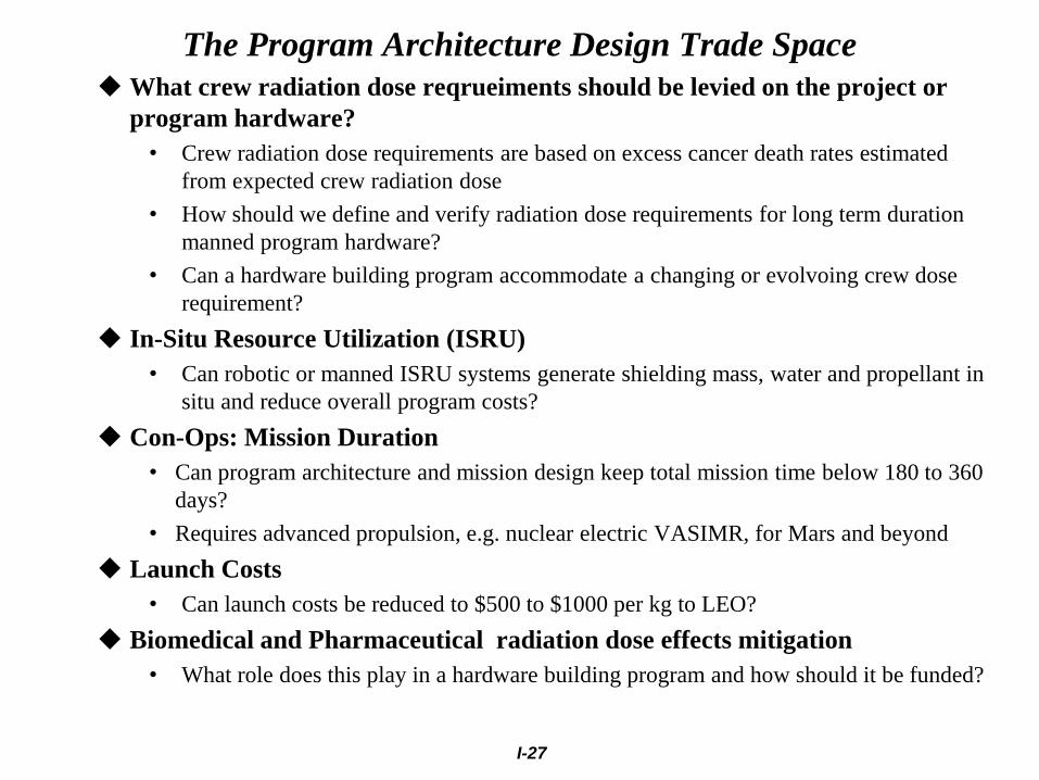
The Program Architecture Design Trade Space
What crew radiation dose reqrueiments should be levied on the project or
program hardware?
• Crew radiation dose requirements are based on excess cancer death rates estimated
from expected crew radiation dose
• How should we define and verify radiation dose requirements for long term duration
manned program hardware?
• Can a hardware building program accommodate a changing or evolvoing crew dose
requirement?
In-Situ Resource Utilization (ISRU)
• Can robotic or manned ISRU systems generate shielding mass, water and propellant in
situ and reduce overall program costs?
Con-Ops: Mission Duration
• Can program architecture and mission design keep total mission time below 180 to 360
days?
• Requires advanced propulsion, e.g. nuclear electric VASIMR, for Mars and beyond
Launch Costs
• Can launch costs be reduced to $500 to $1000 per kg to LEO?
Biomedical and Pharmaceutical radiation dose effects mitigation
• What role does this play in a hardware building program and how should it be funded?

The Vehicle Design Trade Space
Materials selection and habitat configuration
• Minimize use of structural aluminum and high-Z, low-hydrogen content materials
• limited return on investment expected here on account of secondary particle
showers in the human body itself
• New low-Z, high hydrogen content structural material must meet an array of safety
and reliability requirements independent of radiation performance
• Iterative design (material and configuration) for optimization of spacecraft shielding
performance for the crew
• Wherever possible, every gram of spacecraft mass should be performing two
functions – the basic function and a shielding mass function
• Maximize areal density of spacecraft mass around crew quarters
Crew GCR (and SPE) radiation dose and propulsion system design trades
• Nuclear electric, vs. solar electric vs. chemical – what is the most cost effective way to
power a sprint mission (180-360 days) to Mars at the integrated spacecraft system level?
Con-Ops: limit crew time outside small, heavily shielded volumes inside habitat
• Combine crew quarters and SPE shelter functions?
• Crew quarters and overall habitat volume trade space – more shielding volume means
more shielding mass cost
I-28

Near Term Epic Challenges Spacecraft structural and shielding materials development
Reducing spacecraft weight is always a good thing and is one motivation for reducing
atomic number and increasing hydrogen content
However, the expected crew dose benefits, even at 120 g/cm2, are limited
One possible exception is the use of liquid hydrogen or hydrogen adsorbed in
nanoporous solids
Increase storage temperature and reduce thermal control burden
Extend shielding effectiveness studies beyond the traditional limit of about 100 g/cm2
Accelerator and Monte Carlo simulation (e.g. FLUKA) studies at areal densities between 100
and 1000 g/cm2 – where is the greatest useful dose reduction ?
Moving forward on active shielding
Magnet coil configurations that dramatically reduce structural loading and support
structure mass requirements
Reduce power and cooling requirements
Keep the field out of the crew cabin
In-Situ Resource Utilization (ISRU) technology development
We can’t afford to launch shielding mass; but perhaps we can we afford to launch
smart ISRU machinery to produce the needed shielding, water, and propellant mass in
space from asteroidal, lunar, and Martian resources?
Can large program cost reductions be achieved compared to launching shielding
mass, water and propellant from Earth?
I-29

Long Term Epic Challenges Biomedical and Pharmaceutical Research
More certainty in the relationship between space radiation dose and estimated crew
health risks
Cancer, Heart Disease, Central Nervous System Effects
Removing the enormous uncertainty in the existing health effects estimates may lead to
higher crew dose limits and longer acceptable mission times with lower shielding
requirements
Long term program – 10 years to first products at least
Pharmaceutical Mitigation of Space Radiation Health Effects
If successful, this approach could dramatically reduce both health risk and shielding mass
reqrueiments
Long term program – 10 years to first products at least
Possible NASA “Spin-off” products of general benefit in reducing health care costs and
treating disease.
Promising early results reported at the 22nd Annual NASA Space Radiation Investigators
Workshop ( Sept 18-21, 2011, League City ,Texas) from several groups
Advanced Propulsion and Power
Space Nuclear Power
Next generation (Gen-4) fission reactor concepts
Flight safety
Public safety
Nuclear Electric Propulsion - VASIMR
I-30

SUPPORTING MATERIALS
I-31
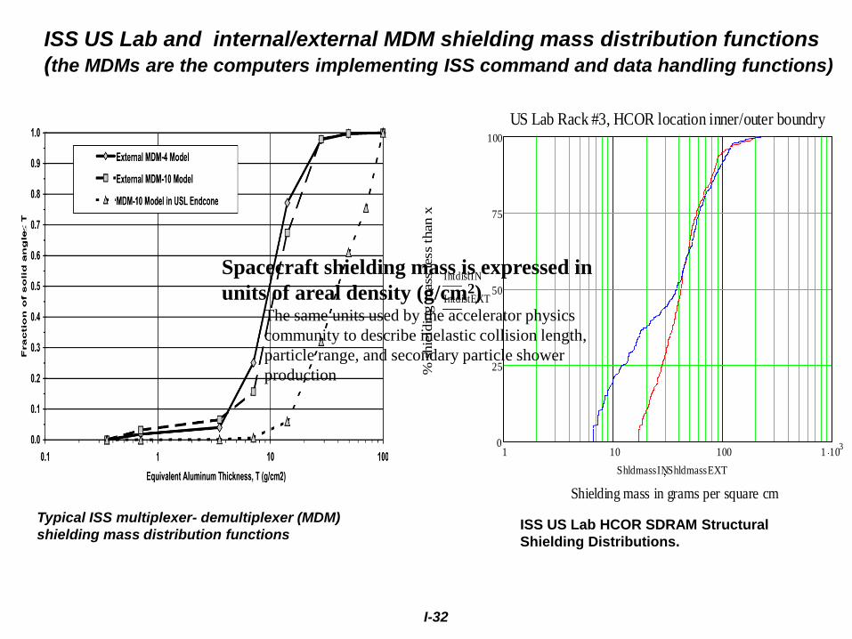
I-32
Typical ISS multiplexer- demultiplexer (MDM)
shielding mass distribution functions
1 10 100 1 1030
25
50
75
100
US Lab Rack #3, HCOR location inner/outer boundry
Shielding mass in grams per square cm
% s
hie
ldin
g m
ass
less
than x
IntdistIN
IntdistEXT
ShldmassINShldmassEXT
ISS US Lab HCOR SDRAM Structural
Shielding Distributions.
ISS US Lab and internal/external MDM shielding mass distribution functions
(the MDMs are the computers implementing ISS command and data handling functions)
Spacecraft shielding mass is expressed in
units of areal density (g/cm2) The same units used by the accelerator physics
community to describe inelastic collision length,
particle range, and secondary particle shower
production

I-33

I-34
SSP-30512 DESIGN/VERIFICATION ENVIRONMENT, 500 KM ALTITUDE COLSA-RTD-ISS-DR-03-008-DOC-B, MSFC, 2003

I-35
GCR-Matter Interactions 1 - Electromagnetic Force
High speed charged particles decelerate by loosing energy to target substance
electrons during columbic collisions leaving an ionization/damage track
Nuclear collisions contribute make little contribution to deceleration except at the lowest
kinetic energies near end of track.
http://pdg.lbl.gov/2010/reviews/rpp2010-rev-passage-particles-matter.pdf
dE/dx is the rate of energy transfer: KeV/micron or MeV-cm2/mg
Linear and nearly constant over most of the particle range - hence the term linear energy
transfer (LET)
Nonlinear neat end of track – most of the energy is deposited near the end of track in the
“Brag Peak”; basis of accelerator hadron therapy for certain cancers
Quantified by the relativistic Bethe-Bloch equation (only accounts for electronic
stopping)
β = v / c, v = velocity of the particle , E = energy of the particle, x = distance travelled by the particle , c =
speed of light, z = particle charge , e = charge of the electron, me = rest mass of the electron, n = electron
density of the target , I = mean excitation potential of the target , ε0 = vacuum permittivity
I = 10eV(Z), n = (NA Z ρ)/A Mμ ; ρ = density of the target, Z = target atomic number , A = target mass number,
NA = Avogadro number, and Mu = Molar mass constant = 1 in Si units
Note that the properties of the target appear only in the n, ln(1/I ), Z/A and ρ terms
Widely utilized (free) on-line or downloadable Bethe-Bloch LET and
range calculators that will run on your PC
http://www.srim.org/ (includes nuclear stopping at the lowest kinetic energies)
http://tvdg10.phy.bnl.gov/
35

I-36

I-37
GCR - Matter Interactions II – The Strong or Nuclear Force:
Rules of thumb for relativistic nuclear collisions and secondary particle showers
Inelastic collisions attenuate the primary flux
exponentially and generate secondary particles
N(l) = N(0) exp(-l/λ), λ = inelastic collision
length (grams/cm2) , l = thickness in g/cm2
http://pdg.lbl.gov/2010/reviews/rpp2010-rev-atomic-
nuclear-prop.pdf
λ ranges from 42 g/cm2 to 118 g/cm2 for
protons in various materials
» At fixed target mass, number of collisions
decreases with increasing atomic weight (i.e.
fewer target nuclei per gram)
λ Scales as (projectile atomic number)0.77
λ increases with target atomic number
λ is energy dependent at low (<50 MeV/n)
energies
<nevent> = average number of secondary particles per
collision event
<ncollision> is proportional to A(projectile) x A(target)
x (average nuclear thickness function)
<nshower> is proportional to primary projectile energy
Secondary particles produced in the first collision
expand and propagate the shower via further
collisions with target nuclei as described by
secondary particle λs
37

I-38
38
GCR nuclear collisions as recorded in nuclear
emulsions
Danysz and Pniewski, Philosophical
Magazine 44 348 (1953);
50μ
O.18 mm
Mg nucleus cosmic ray emulsion “star”, i.e. nuclear reaction event Albert Lim (2000), http://astro.com.sg/articles/
Difference_%20btw_Gamma_n_Cosmic_Rays/DiffRays_image001.jpg

I-39