designing with thin gauge - arnoldmagnetics with thin gauge presented by steve constantinides, ......
TRANSCRIPT
© 2008 Arnold Magnetic Technologies
1Our world touches your world every day…
Designing with Thin Gauge
Presented by
Steve Constantinides, Director of TechnologyArnold Magnetic Technologies
SMMA Fall Technical Conference, October 2008
• Demand for electrical device efficiency gains which started decades ago due to economic factors have accelerated, propelled by the unprecedented rise in energy costs and the alleged impact of energy consumption on global weather instability.
© 2008 Arnold Magnetic Technologies
2Our world touches your world every day…
Agenda
• Introduction
• Manufacturing Process
• GOES versus NGOES
• Motor Efficiency
• Loss Factors
• NGO Thin Gauge (Arnon)
• Over the last several years I’ve spoken about permanent magnets. However, the magnetic material that is utilized in far great tonnage than magnets is the family of soft magnetic materials, especially Iron-Silicon whose usage spans both motor/generator and transformer/inductor applications.
• Often referred to as Electrical Steel, Iron Silicon is available in both Grain Oriented (GOES) and Non-Oriented (NGOES) forms.
© 2008 Arnold Magnetic Technologies
3Our world touches your world every day…
Two Main Applications for Electrical Steel
Handbook of Small Electric Motors
Switched Reluctance Motorsand their Control, p.154T.J.E. Miller
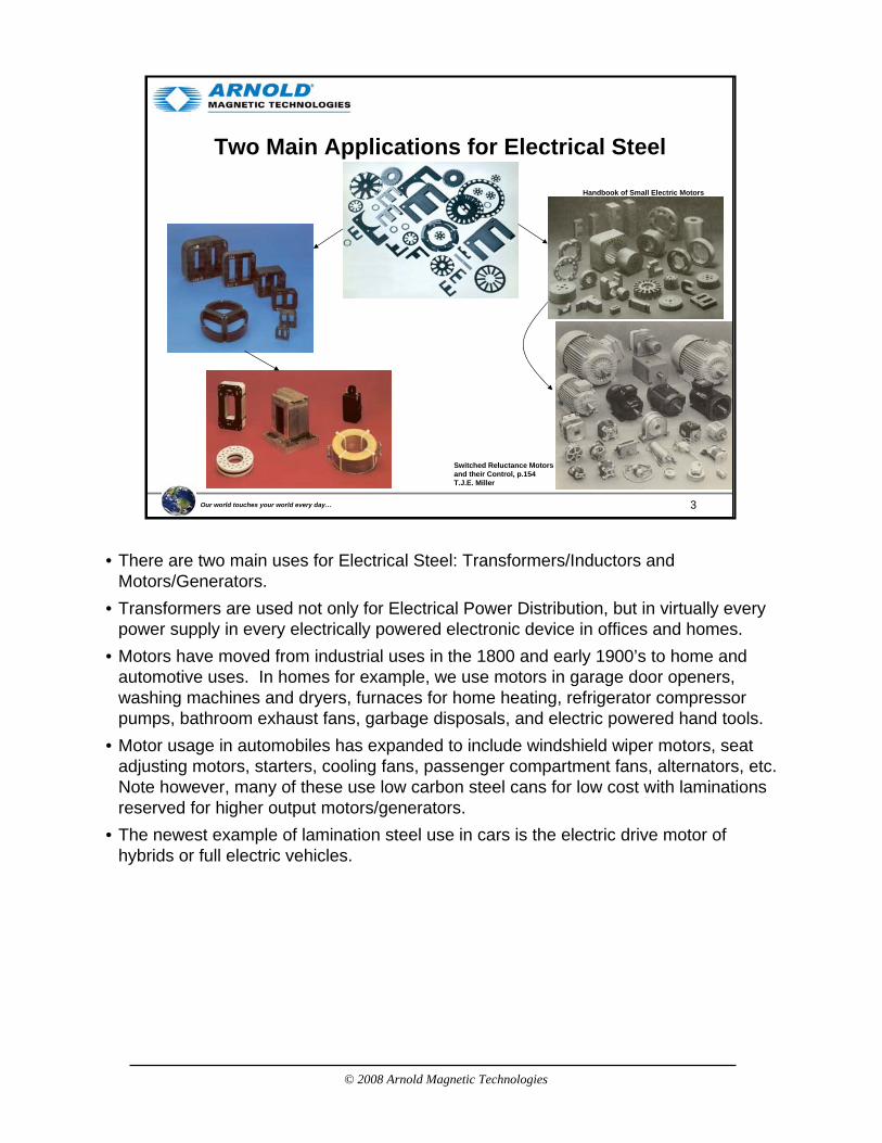
• There are two main uses for Electrical Steel: Transformers/Inductors and Motors/Generators.
• Transformers are used not only for Electrical Power Distribution, but in virtually every power supply in every electrically powered electronic device in offices and homes.
• Motors have moved from industrial uses in the 1800 and early 1900’s to home and automotive uses. In homes for example, we use motors in garage door openers, washing machines and dryers, furnaces for home heating, refrigerator compressor pumps, bathroom exhaust fans, garbage disposals, and electric powered hand tools.
• Motor usage in automobiles has expanded to include windshield wiper motors, seat adjusting motors, starters, cooling fans, passenger compartment fans, alternators, etc. Note however, many of these use low carbon steel cans for low cost with laminations reserved for higher output motors/generators.
• The newest example of lamination steel use in cars is the electric drive motor of hybrids or full electric vehicles.

© 2008 Arnold Magnetic Technologies
4Our world touches your world every day…
Agenda
• Introduction
• Manufacturing Process
• GOES versus NGOES
• Motor Efficiency
• Loss Factors
• NGO Thin Gauge (Arnon)
• Higher frequency operation is possible because of reduced eddy current related loss in select lamination materials.
• Iron-Silicon laminations are more expensive than low carbon steel and their use has been reserved for high energy density, high rpm motors and generators.
• In defense of the manufacturers, the process for making lamination-ready Fe-Si strip involves many processing steps and utilizes expensive manufacturing equipment.
© 2008 Arnold Magnetic Technologies
5Our world touches your world every day…
Manufacturing Steps, NGOES
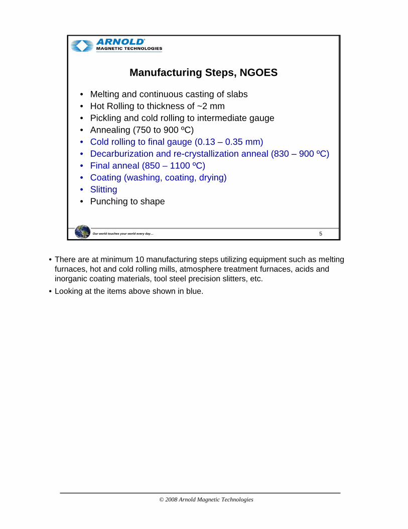
• Melting and continuous casting of slabs• Hot Rolling to thickness of ~2 mm• Pickling and cold rolling to intermediate gauge• Annealing (750 to 900 ºC)• Cold rolling to final gauge (0.13 – 0.35 mm)• Decarburization and re-crystallization anneal (830 – 900 ºC)• Final anneal (850 – 1100 ºC)• Coating (washing, coating, drying)• Slitting• Punching to shape
• There are at minimum 10 manufacturing steps utilizing equipment such as melting furnaces, hot and cold rolling mills, atmosphere treatment furnaces, acids and inorganic coating materials, tool steel precision slitters, etc.
• Looking at the items above shown in blue.
© 2008 Arnold Magnetic Technologies
6Our world touches your world every day…
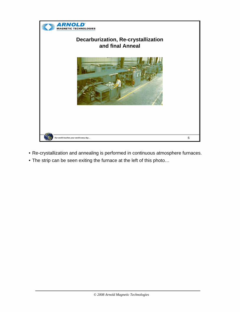
Decarburization, Re-crystallizationand final Anneal
• Re-crystallization and annealing is performed in continuous atmosphere furnaces.• The strip can be seen exiting the furnace at the left of this photo…
© 2008 Arnold Magnetic Technologies
7Our world touches your world every day…
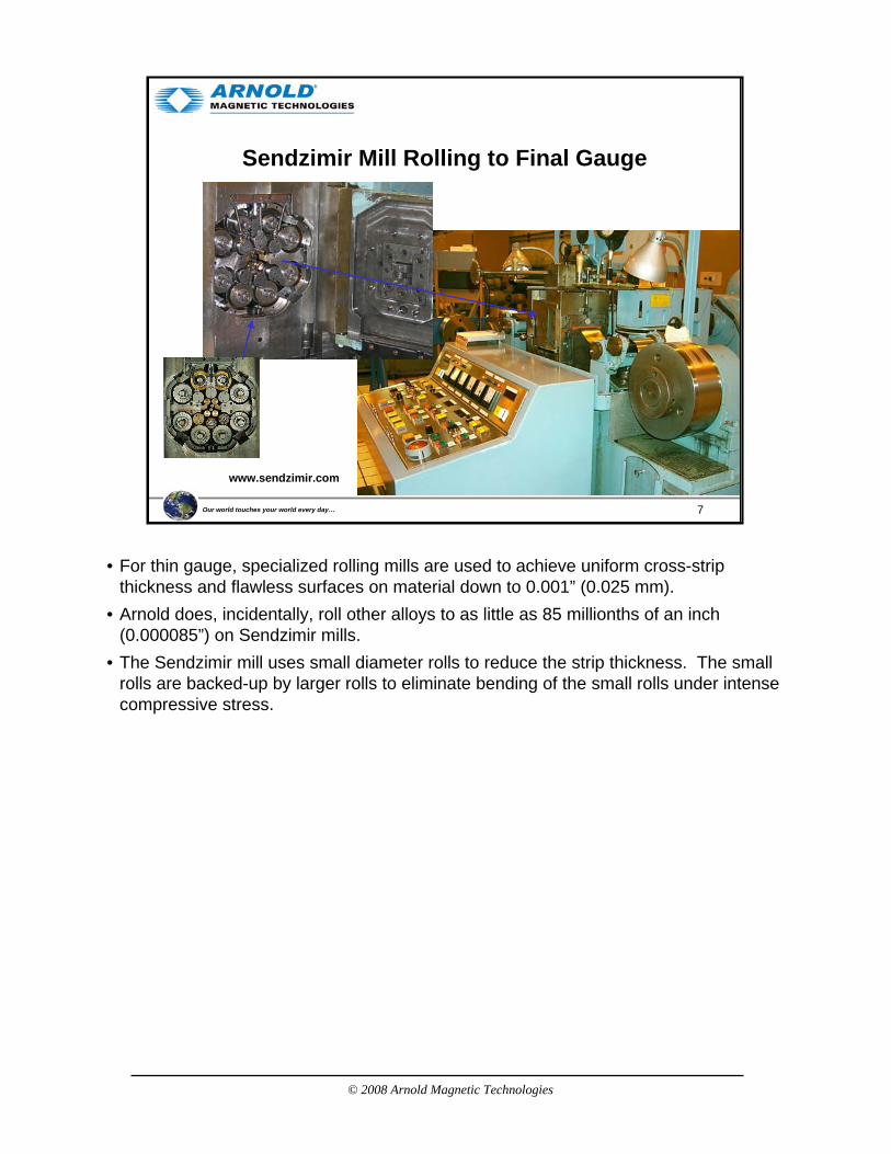
Sendzimir Mill Rolling to Final Gauge
www.sendzimir.com
• For thin gauge, specialized rolling mills are used to achieve uniform cross-strip thickness and flawless surfaces on material down to 0.001” (0.025 mm).
• Arnold does, incidentally, roll other alloys to as little as 85 millionths of an inch (0.000085”) on Sendzimir mills.
• The Sendzimir mill uses small diameter rolls to reduce the strip thickness. The small rolls are backed-up by larger rolls to eliminate bending of the small rolls under intense compressive stress.
© 2008 Arnold Magnetic Technologies
8Our world touches your world every day…
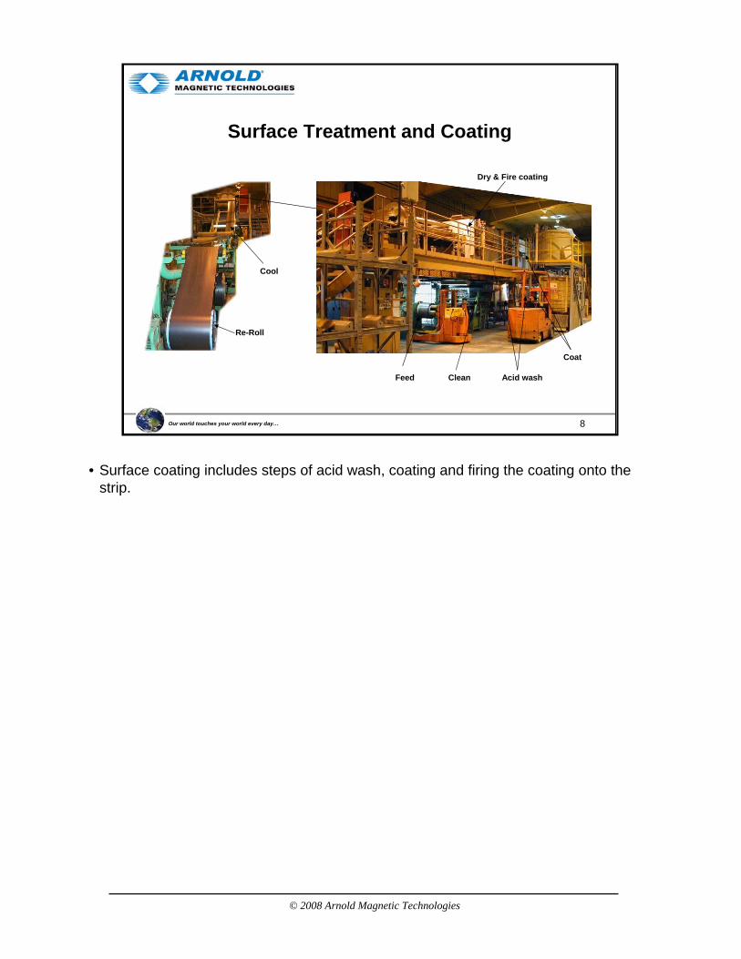
Surface Treatment and Coating
Feed
Coat
Acid washClean
Dry & Fire coating
Cool
Re-Roll
• Surface coating includes steps of acid wash, coating and firing the coating onto the strip.
© 2008 Arnold Magnetic Technologies
9Our world touches your world every day…
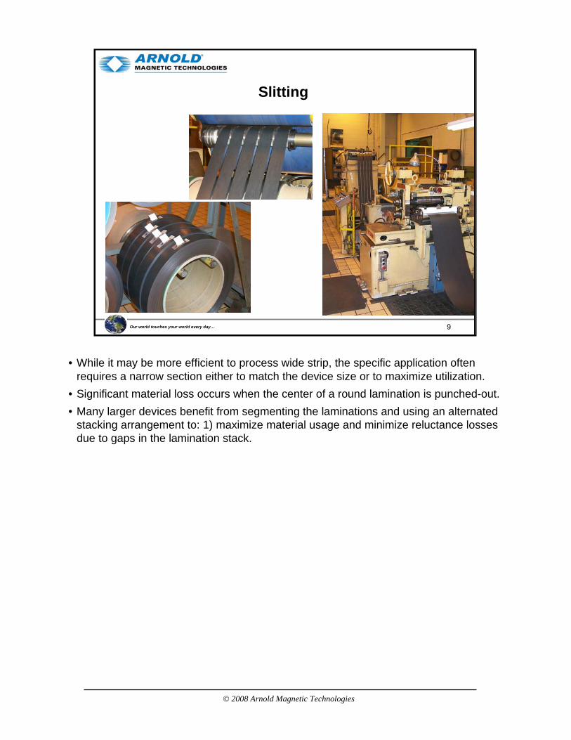
Slitting
• While it may be more efficient to process wide strip, the specific application often requires a narrow section either to match the device size or to maximize utilization.
• Significant material loss occurs when the center of a round lamination is punched-out.• Many larger devices benefit from segmenting the laminations and using an alternated
stacking arrangement to: 1) maximize material usage and minimize reluctance losses due to gaps in the lamination stack.

© 2008 Arnold Magnetic Technologies
10Our world touches your world every day…
Agenda
• Introduction
• Manufacturing Process
• GOES versus NGOES
• Motor Efficiency
• Loss Factors
• NGO Thin Gauge (Arnon)
• Grain Oriented and Non-Grain Oriented Electrical Steel.
© 2008 Arnold Magnetic Technologies
11Our world touches your world every day…
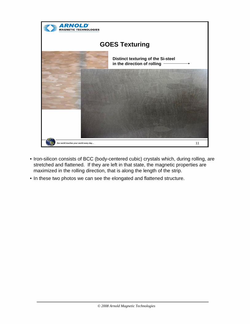
GOES Texturing
Distinct texturing of the Si-steel in the direction of rolling
• Iron-silicon consists of BCC (body-centered cubic) crystals which, during rolling, are stretched and flattened. If they are left in that state, the magnetic properties are maximized in the rolling direction, that is along the length of the strip.
• In these two photos we can see the elongated and flattened structure.
© 2008 Arnold Magnetic Technologies
12Our world touches your world every day…
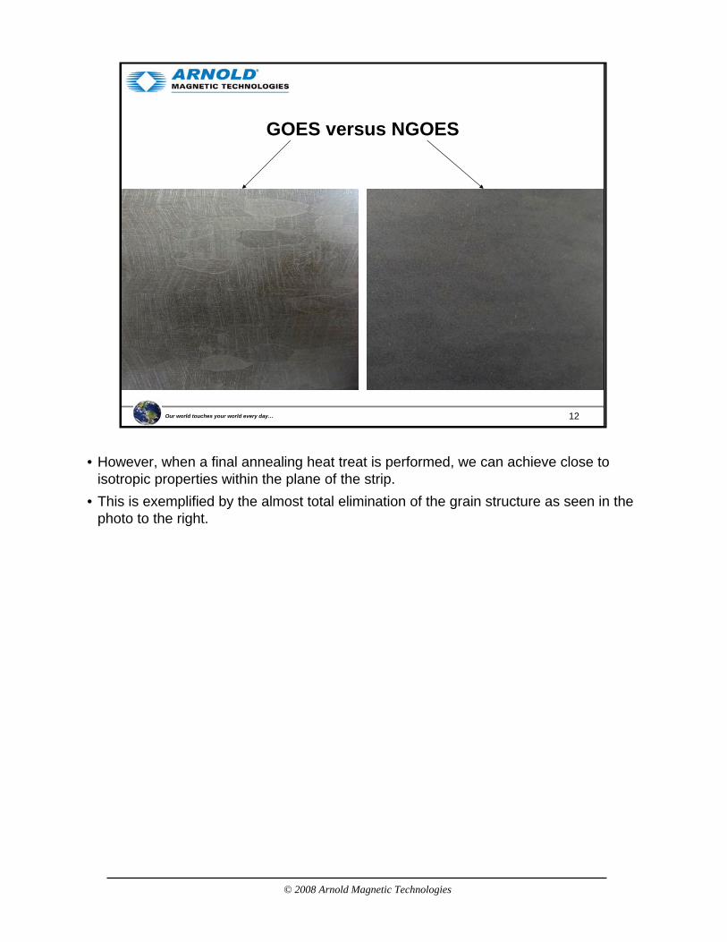
GOES versus NGOES
• However, when a final annealing heat treat is performed, we can achieve close to isotropic properties within the plane of the strip.
• This is exemplified by the almost total elimination of the grain structure as seen in the photo to the right.

© 2008 Arnold Magnetic Technologies
13Our world touches your world every day…
Directional Properties of Si-Steel (GOES)
• This chart from AK steel for grain oriented silicon iron illustrates the difference in magnetic properties in the rolling direction (straight up and down) and at angles at up to 90º from the rolling direction (left to right).
• Maximum performance is achieved by application of the material with the strip in the same direction that flux is expected.
• In contrast, NGOES shows only a 10-20% variation in properties within the plane of the strip and can be used in any orientation.
© 2008 Arnold Magnetic Technologies
14Our world touches your world every day…
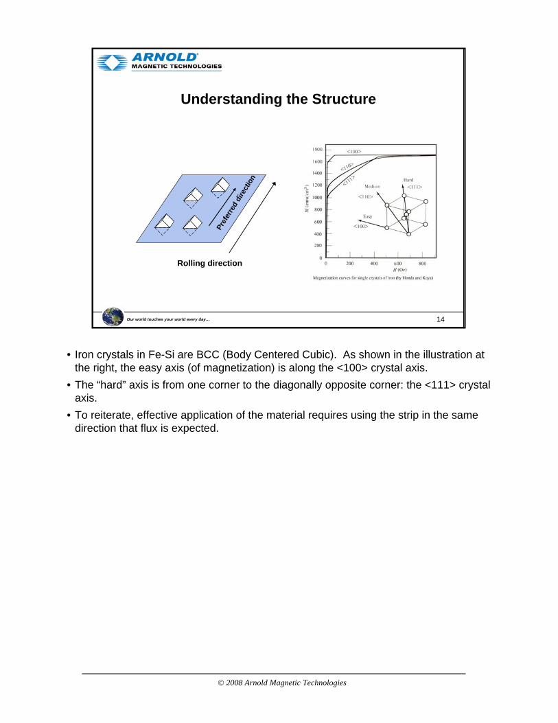
Understanding the Structure
Pref
erre
d di
rect
ion
Rolling direction
• Iron crystals in Fe-Si are BCC (Body Centered Cubic). As shown in the illustration at the right, the easy axis (of magnetization) is along the <100> crystal axis.
• The “hard” axis is from one corner to the diagonally opposite corner: the <111> crystal axis.
• To reiterate, effective application of the material requires using the strip in the same direction that flux is expected.
© 2008 Arnold Magnetic Technologies
15Our world touches your world every day…
Agenda
• Introduction
• Manufacturing Process
• GOES versus NGOES
• Motor Efficiency
• Loss Factors
• NGO Thin Gauge (Arnon)
Discussion regarding the use of Fe-Si needs to include consideration of motor efficiency to justify the more expensive material (i.e., more expensive than low carbon steel).
© 2008 Arnold Magnetic Technologies
16Our world touches your world every day…
Motor Efficiency
“…~57% of the generated electric energy in the United States is utilized [consumed] by electric motors powering industrial equipment. In addition, more than 95% of an electric motor’s life-cycle cost is the energy cost.”
The Next Generation Motor, IEEE Industry Applications, January / February 2008, p.37
© 2008 Arnold Magnetic Technologies
17Our world touches your world every day…
Electric Operating Cost
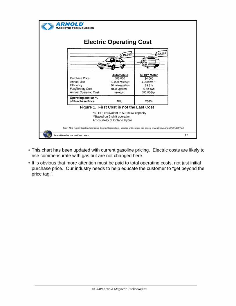
Figure 1. First Cost is not the Last Cost*60 HP; equivalent to 50.18 kw capacity**Based on 2-shift operationArt courtesy of Ontario Hydro
From AEC (North Carolina Alternative Energy Corporation), updated with current gas prices, www.p2pays.org/ref/17/16897.pdf
$3.50$1400
9%
• This chart has been updated with current gasoline pricing. Electric costs are likely to rise commensurate with gas but are not changed here.
• It is obvious that more attention must be paid to total operating costs, not just initial purchase price. Our industry needs to help educate the customer to “get beyond the price tag.”.
© 2008 Arnold Magnetic Technologies
18Our world touches your world every day…
Motor Efficiency
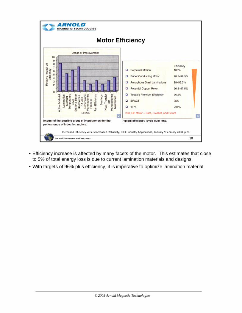
Increased Efficiency versus Increased Reliability, IEEE Industry Applications, January / February 2008, p.29
• Efficiency increase is affected by many facets of the motor. This estimates that close to 5% of total energy loss is due to current lamination materials and designs.
• With targets of 96% plus efficiency, it is imperative to optimize lamination material.
© 2008 Arnold Magnetic Technologies
19Our world touches your world every day…
Motor Failures and Temperature
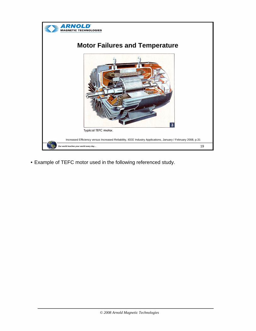
Increased Efficiency versus Increased Reliability, IEEE Industry Applications, January / February 2008, p.31
• Example of TEFC motor used in the following referenced study.

© 2008 Arnold Magnetic Technologies
20Our world touches your world every day…
Motor Failures and Temperature
Increased Efficiency versus Increased Reliability, IEEE Industry Applications, January / February 2008, p.31
• Bearings and stator windings are the two most common causes of failure in a typical TEFC motor.
• One of the most severe detractors to long life is heat most of which originates in motor inefficiency.
• Per the article: “…every 10 ºC reduction in [wire] insulation temperature doubles the insulation life.”
© 2008 Arnold Magnetic Technologies
21Our world touches your world every day…
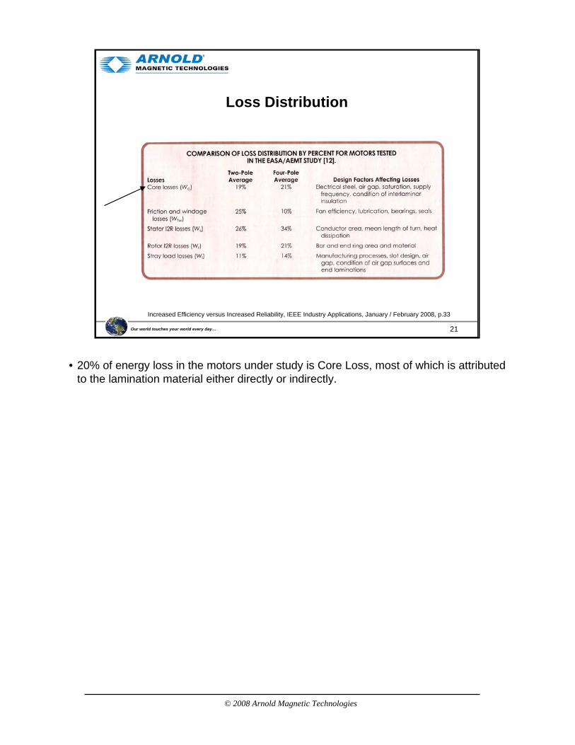
Loss Distribution
Increased Efficiency versus Increased Reliability, IEEE Industry Applications, January / February 2008, p.33
• 20% of energy loss in the motors under study is Core Loss, most of which is attributed to the lamination material either directly or indirectly.
© 2008 Arnold Magnetic Technologies
22Our world touches your world every day…
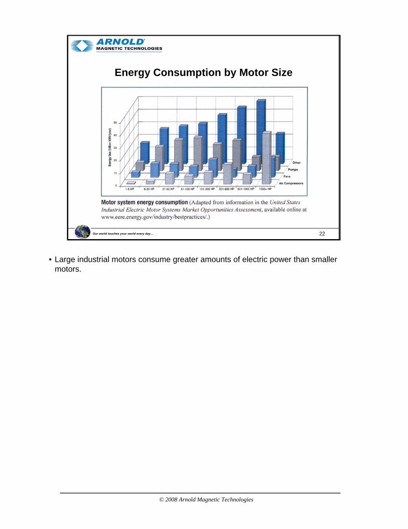
Energy Consumption by Motor Size
• Large industrial motors consume greater amounts of electric power than smaller motors.
© 2008 Arnold Magnetic Technologies
23Our world touches your world every day…
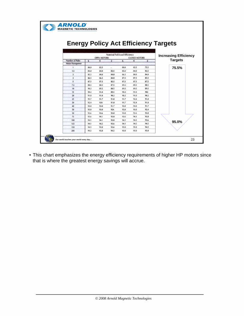
Energy Policy Act Efficiency Targets
Increasing EfficiencyTargets
75.5%
95.0%
• This chart emphasizes the energy efficiency requirements of higher HP motors since that is where the greatest energy savings will accrue.

© 2008 Arnold Magnetic Technologies
24Our world touches your world every day…
Additional Motor Efficiency Information
• Energy Efficient Electric Motor Selection Handbook– www.wbdg.org/ccb/DOE/TECH/ce0384.pdf
• Buying an Energy Efficient Electric Motor– www1.eere.energy.gov/industry/bestpractices/pdfs/mc-0382.pdf
• Consortium for Energy Efficiency– www.cee1.org/ind/mot-sys/mtr-ms-main.php3
• Efficient Electric Motor Systems for Industry– www.osti.gov/bridge/servlets/purl/10112522-FoENQM/webviewable/10112522.PDF
• Efficient Electric Motor Systems: SEEEM– www.asiapacificpartnership.org/BATF/BATF%20Projects%20Workshops/Motors%20
WS-SEEEM-brunner.pdf• Development of Ultra-Efficient Electric Motors
– www.osti.gov/bridge/servlets/purl/928973-hsePV1/928973.PDF• Electric Motor Systems in Developing Countries: Opportunities for Efficiency
Improvement– www.osti.gov/bridge/servlets/purl/10187187-n23Ohm/native/10187187.PDF
• There is a wealth of information on the internet. Here are just a few additional useful links.
© 2008 Arnold Magnetic Technologies
25Our world touches your world every day…
Agenda
• Introduction
• Manufacturing Process
• GOES versus NGOES
• Motor Efficiency
• Loss Factors
• NGO Thin Gauge (Arnon)
• Fe-Si is more expensive than low carbon steel and thin gauge Fe-Si is more expensive than thick gauge.
• Therefore, to justify the usage of thin gauge Fe-Si, there must be an advantage to counterbalance the higher cost.
© 2008 Arnold Magnetic Technologies
26Our world touches your world every day…
Loss VariablesInput Variables-1 Input Variables-2 Loss contributors Loss
Frequency Eddy Current Loss HeatSkin Effect
Applied field strengthHysteresis
Field Orientation (max perm, Hc, Bsat) Hysteretic Loss
Lamination ThicknessResistivity (Material)
Anomolous LossResistance (Interlam)
Lam Insul Thickness
Lam flatness Stacking Factor Energy Transfer("Efficiency")
Winding ArrangementInterlam vibration
Magnetostriction (Noise)
Thermal characteristics(Material)
Electrical Coil Resistance
Mechanical Friction
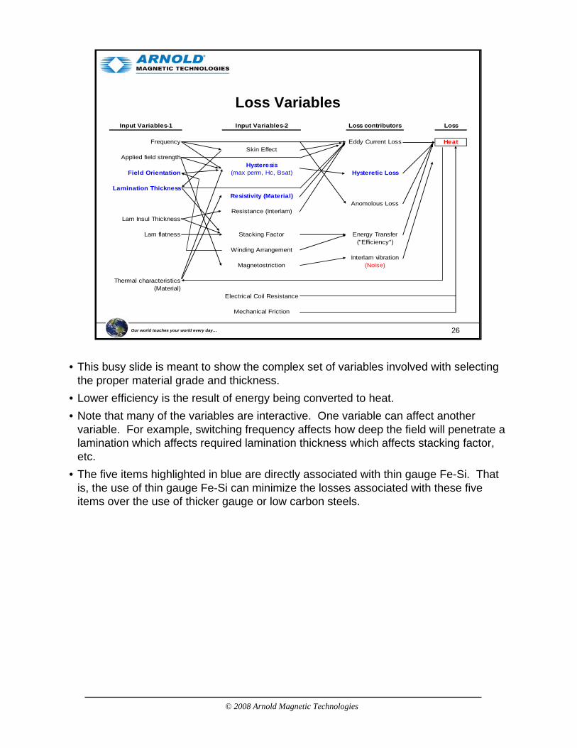
• This busy slide is meant to show the complex set of variables involved with selecting the proper material grade and thickness.
• Lower efficiency is the result of energy being converted to heat.• Note that many of the variables are interactive. One variable can affect another
variable. For example, switching frequency affects how deep the field will penetrate a lamination which affects required lamination thickness which affects stacking factor, etc.
• The five items highlighted in blue are directly associated with thin gauge Fe-Si. That is, the use of thin gauge Fe-Si can minimize the losses associated with these five items over the use of thicker gauge or low carbon steels.
© 2008 Arnold Magnetic Technologies
27Our world touches your world every day…
Loss Variable CategoriesInput Variables-1 Input Variables-2 Loss contributors Loss
Frequency Eddy Current Loss HeatSkin Effect
Applied field strengthHysteresis
Field Orientation (max perm, Hc, Bsat) Hysteretic Loss
Lamination ThicknessResistivity (Material)
Anomolous LossResistance (Interlam)
Lam Insul Thickness
Lam flatness Stacking Factor Energy Transfer("Efficiency")
Winding ArrangementInterlam vibration
Magnetostriction (Noise)
Thermal characteristics(Material)
Electrical Coil Resistance
Mechanical Friction
Material Resistivity5:
Magnetostriction4:
Laminations3:
Eddy Current2:
Hysteresis1:
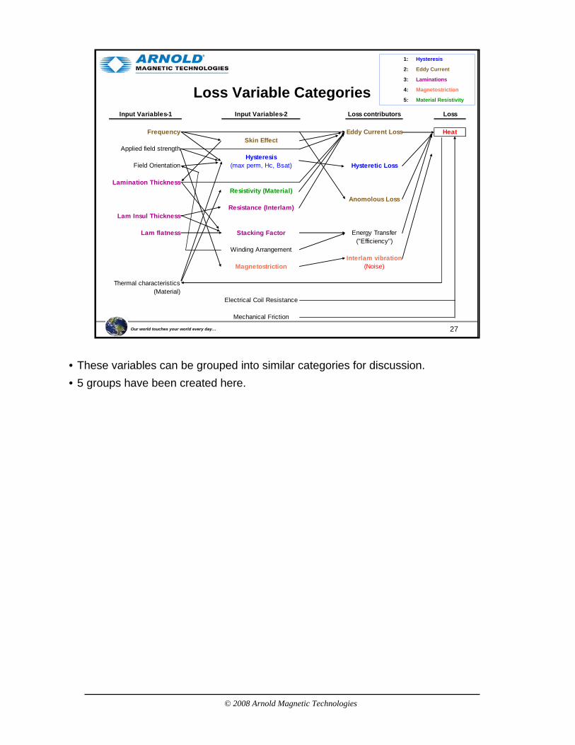
• These variables can be grouped into similar categories for discussion. • 5 groups have been created here.
© 2008 Arnold Magnetic Technologies
28Our world touches your world every day…
Waveforms
Table 1.1 Maximum Flux Density Formulas for Commonly Occurring Functions
Note: In these formulas N is the number of turns in the winding across which the voltage is developed. A is the cross-sectional area of the core around which the winding is placed. If the area is expressed in square centimeters, the flux density will be in gauss. If the area is expressed in square inches, the flux density will be in maxwells per square inch. Time t is in seconds. Frequency f is in hertz. Voltage E in in volts. Current Iis in amperes. Inductance L is in henries.
Handbook of Transformer Design & Application, p. 1.6
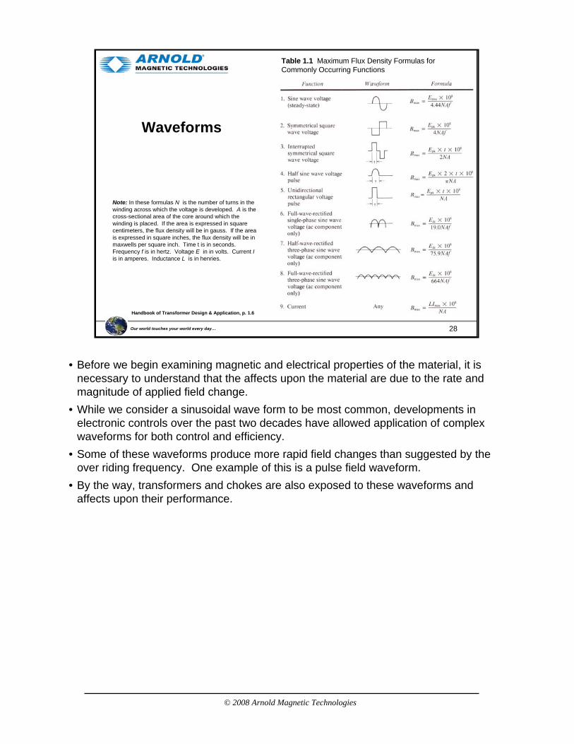
• Before we begin examining magnetic and electrical properties of the material, it is necessary to understand that the affects upon the material are due to the rate and magnitude of applied field change.
• While we consider a sinusoidal wave form to be most common, developments in electronic controls over the past two decades have allowed application of complex waveforms for both control and efficiency.
• Some of these waveforms produce more rapid field changes than suggested by the over riding frequency. One example of this is a pulse field waveform.
• By the way, transformers and chokes are also exposed to these waveforms and affects upon their performance.
© 2008 Arnold Magnetic Technologies
29Our world touches your world every day…
Indu
ctio
n, B
(Gau
ss)
1: Hysteresis Curve
Applied Field, H (Oersted)
B saturation
B remanance
Hccoercivity
Material Resistivity5:
Magnetostriction4:
Laminations3:
Eddy Current2:
Hysteresis1:
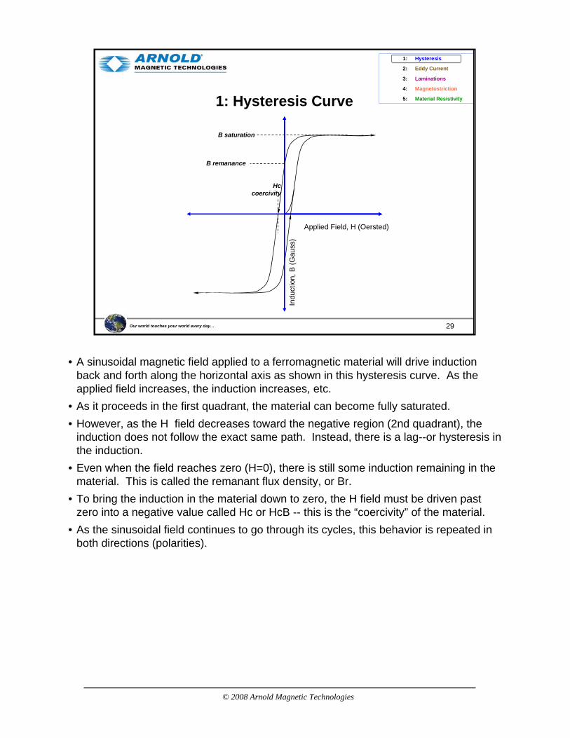
• A sinusoidal magnetic field applied to a ferromagnetic material will drive induction back and forth along the horizontal axis as shown in this hysteresis curve. As the applied field increases, the induction increases, etc.
• As it proceeds in the first quadrant, the material can become fully saturated.• However, as the H field decreases toward the negative region (2nd quadrant), the
induction does not follow the exact same path. Instead, there is a lag--or hysteresis in the induction.
• Even when the field reaches zero (H=0), there is still some induction remaining in the material. This is called the remanant flux density, or Br.
• To bring the induction in the material down to zero, the H field must be driven past zero into a negative value called Hc or HcB -- this is the “coercivity” of the material.
• As the sinusoidal field continues to go through its cycles, this behavior is repeated in both directions (polarities).
© 2008 Arnold Magnetic Technologies
30Our world touches your world every day…
1: Hysteresis Loss
Applied Field, H (Oersted)
Indu
ctio
n, B
(Gau
ss)
Bsaturation
Bremanance
Hc
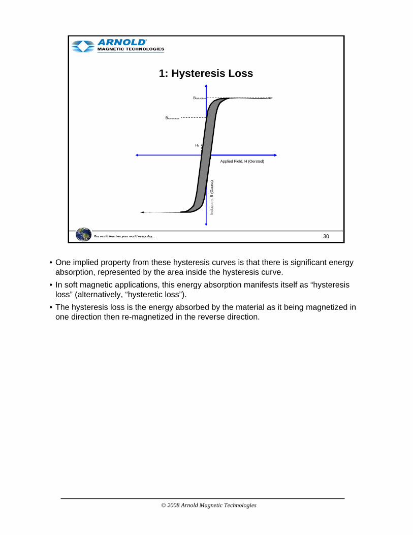
• One implied property from these hysteresis curves is that there is significant energy absorption, represented by the area inside the hysteresis curve.
• In soft magnetic applications, this energy absorption manifests itself as “hysteresis loss” (alternatively, “hysteretic loss”).
• The hysteresis loss is the energy absorbed by the material as it being magnetized in one direction then re-magnetized in the reverse direction.

© 2008 Arnold Magnetic Technologies
31Our world touches your world every day…
1: Hysteresis Curve - Minor Loops8000
6000
4000
2000
0
-2000
-4000
-6000
8000-20 -12 -4 0 4 12 20
FIELD STRENGTH, H (Oe)
IND
UC
TIO
N, B
(GA
US
S)
Matches DC Mag curve
• In a PM motor, the material is unlikely to be driven to saturation. As a result, the material will be using “minor” loop properties.
• This is a series of super-imposed minor hysteresis curves. It can be clearly seen that the induction response differs greatly depending upon the level of applied field.
• The energy loss will be equal to the area within the specific minor loop experienced by the lamination material.
• Since not all the material will see the same externally applied field, there will be unequal energy loss from spot to spot within the lamination structure.
• The more square loop the material, the greater the sensitivity to small changes in applied field.
© 2008 Arnold Magnetic Technologies
32Our world touches your world every day…
1: Hysteresis Loss - Frequency Effects
Applied Field, H (Oersted)In
duct
ion,
B (G
auss
)
Low FrequencyHigh Frequency
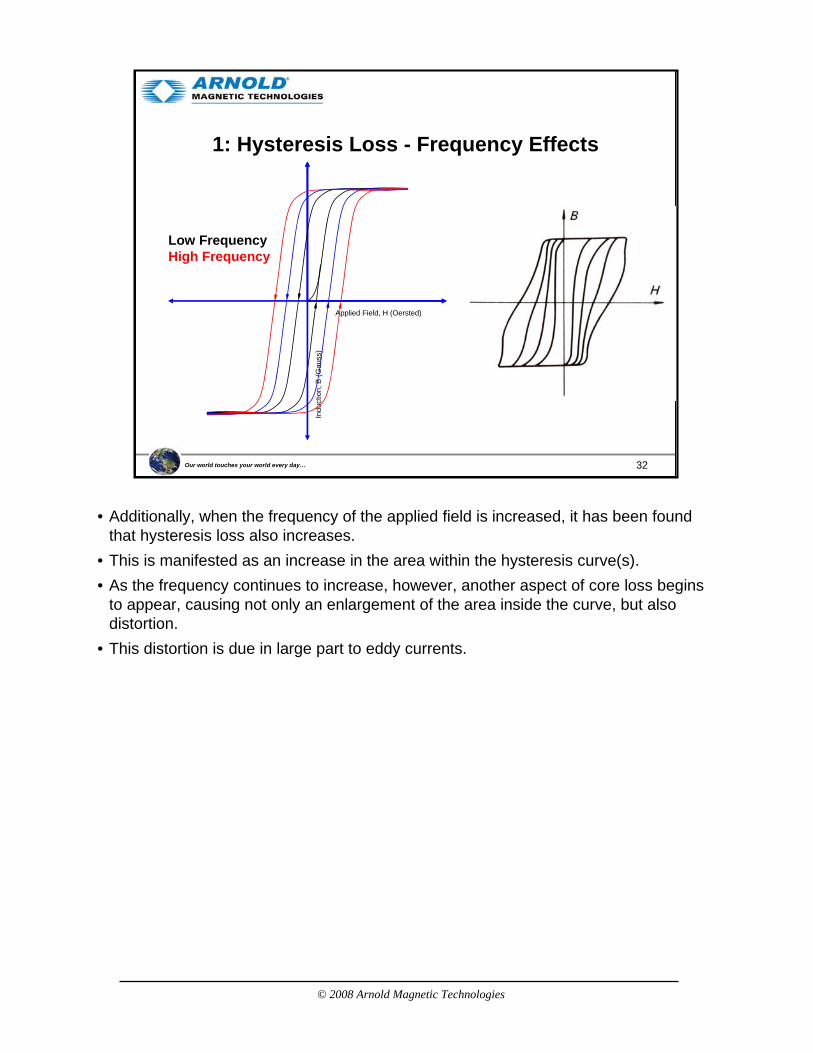
• Additionally, when the frequency of the applied field is increased, it has been found that hysteresis loss also increases.
• This is manifested as an increase in the area within the hysteresis curve(s). • As the frequency continues to increase, however, another aspect of core loss begins
to appear, causing not only an enlargement of the area inside the curve, but also distortion.
• This distortion is due in large part to eddy currents.
© 2008 Arnold Magnetic Technologies
33Our world touches your world every day…
2: Eddy Current Loss
NS
Material Resistivity5:
Magnetostriction4:
Laminations3:
Eddy Current2:
Hysteresis1:
http://hyperphysics.phy-astr.gsu.edu/hphys.html
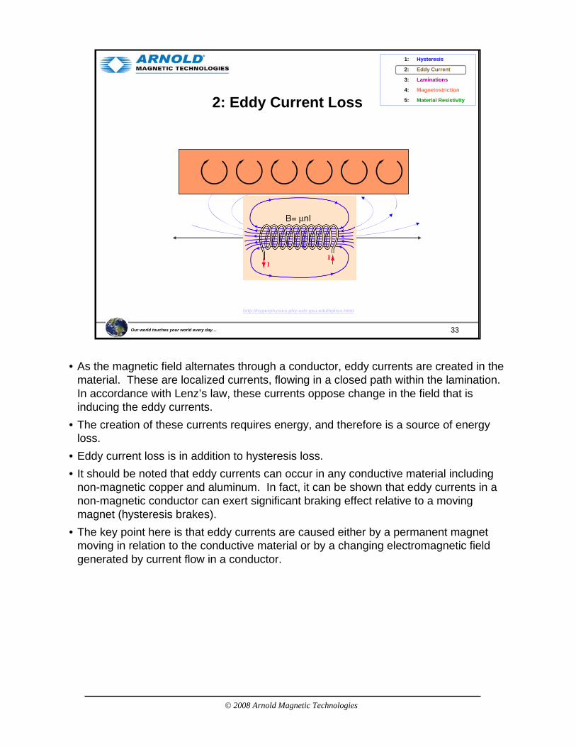
• As the magnetic field alternates through a conductor, eddy currents are created in the material. These are localized currents, flowing in a closed path within the lamination. In accordance with Lenz’s law, these currents oppose change in the field that is inducing the eddy currents.
• The creation of these currents requires energy, and therefore is a source of energy loss.
• Eddy current loss is in addition to hysteresis loss.• It should be noted that eddy currents can occur in any conductive material including
non-magnetic copper and aluminum. In fact, it can be shown that eddy currents in a non-magnetic conductor can exert significant braking effect relative to a moving magnet (hysteresis brakes).
• The key point here is that eddy currents are caused either by a permanent magnet moving in relation to the conductive material or by a changing electromagnetic field generated by current flow in a conductor.
© 2008 Arnold Magnetic Technologies
34Our world touches your world every day…
2: Eddy Current Skin Depth
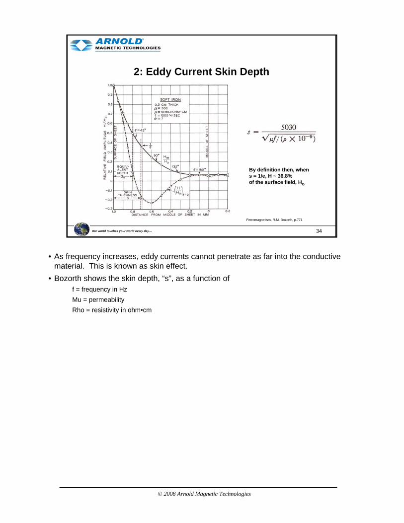
Ferromagnetism, R.M. Bozorth, p.771
By definition then, when s = 1/e, H ~ 36.8% of the surface field, HO
• As frequency increases, eddy currents cannot penetrate as far into the conductive material. This is known as skin effect.
• Bozorth shows the skin depth, “s”, as a function off = frequency in HzMu = permeabilityRho = resistivity in ohm•cm
© 2008 Arnold Magnetic Technologies
35Our world touches your world every day…
2: Eddy Current Skin Depth
Percent of Skin Depth, "s", at 50 Hz
0%
10%
20%
30%
40%
50%
60%
70%
80%
90%
100%
0 500 1,000 1,500 2,000 2,500 3,000 3,500 4,000 4,500 5,000Frequency, Hz
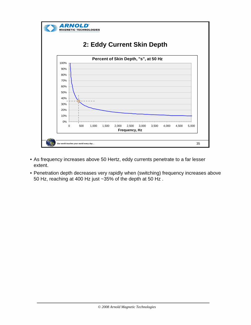
• As frequency increases above 50 Hertz, eddy currents penetrate to a far lesser extent.
• Penetration depth decreases very rapidly when (switching) frequency increases above 50 Hz, reaching at 400 Hz just ~35% of the depth at 50 Hz .
© 2008 Arnold Magnetic Technologies
36Our world touches your world every day…
2: Eddy Current Loss
NS
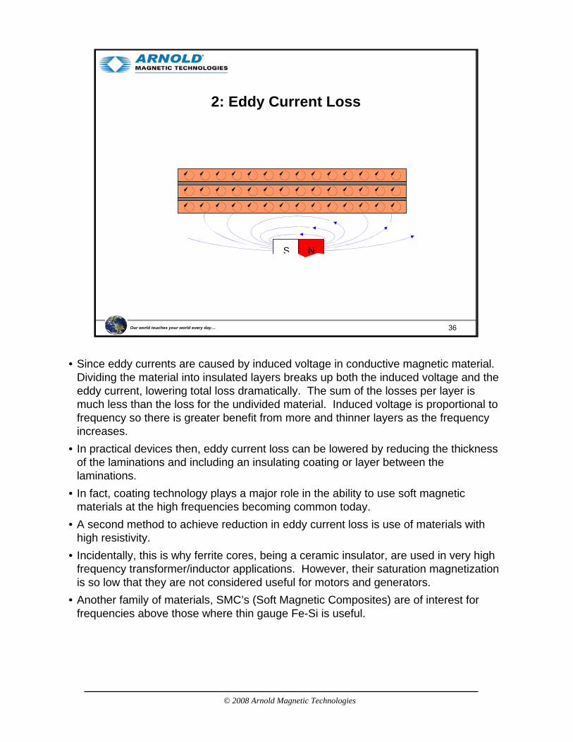
• Since eddy currents are caused by induced voltage in conductive magnetic material. Dividing the material into insulated layers breaks up both the induced voltage and the eddy current, lowering total loss dramatically. The sum of the losses per layer is much less than the loss for the undivided material. Induced voltage is proportional to frequency so there is greater benefit from more and thinner layers as the frequency increases.
• In practical devices then, eddy current loss can be lowered by reducing the thickness of the laminations and including an insulating coating or layer between the laminations.
• In fact, coating technology plays a major role in the ability to use soft magnetic materials at the high frequencies becoming common today.
• A second method to achieve reduction in eddy current loss is use of materials with high resistivity.
• Incidentally, this is why ferrite cores, being a ceramic insulator, are used in very high frequency transformer/inductor applications. However, their saturation magnetization is so low that they are not considered useful for motors and generators.
• Another family of materials, SMC’s (Soft Magnetic Composites) are of interest for frequencies above those where thin gauge Fe-Si is useful.

© 2008 Arnold Magnetic Technologies
37Our world touches your world every day…
2: Fe-Si Resistivity
K1 = Magnetocrystalline Anisotropy constantRho = Electrical Resistivity
Js = Saturation MagnetizationSigma = Yield Stress
Measurement and Characterization of Magnetic Materials, Fausto Fiorillo, p.39
or micro-ohm•cm
• The electrical resistivity of 3% Silicon-iron is approximately 50 micro-ohm• cm.• This is about five times higher than low carbon steel.• Saturation magnetization is reduced by the presence of silicon, dropping by about 6%
with 3% Si. But since the laminations are not driven to saturation in PM motors, this small a drop has negligible affect on normal use.

© 2008 Arnold Magnetic Technologies
38Our world touches your world every day…
2: Core Loss MechanismsSilicon Steel Core Loss
Measurement and Characterization of Magnetic Materials, Fausto Fiorillo, p.31
W = Wh + Wcl + Wexc Where Classical Loss is
• This chart shows the actual measured core loss of a silicon iron lamination structure and the calculated loss components.
• Note that the Hysteresis Loss (Wh) is close to constant with frequency.• The Classical Loss (Wcl, including eddy current loss) is proportional to frequency.• The remaining loss is complex in mechanism, and is often referred to as: Anomalous
Loss, Residual Loss or Excess Loss. It has not yet been satisfactorily explained though efforts are underway to do so.
• Lamination thickness in this example is 0.29 mm under sinusoidal time dependence of polarization.
• Delta = density• d = lamination thickness• Sigma = conductivity• Jp = Peak Polarization• f = frequency
© 2008 Arnold Magnetic Technologies
39Our world touches your world every day…
3: Stacking Factor
75%
80%
85%
90%
95%
100%
0.000 0.010 0.020 0.030 0.040 0.050 0.060 0.070
Stacking Factor
Stacking Factor is limited by: • Strip Flatness • Wedge • Coating Thickness • # of layers
Coating as a % of Lamination Thickness
0%
2%
4%
6%
8%
10%
12%
14%
0.000 0.005 0.010 0.015 0.020 0.025 0.030
Nominal Lamination Thickness, inches
Coat
ing
as a
% o
f Thi
ckne
ss Nominal coating thicknessof 0.000075” per surface
Material Resistivity5:
Magnetostriction4:
Laminations3:
Eddy Current2:
Hysteresis1:
Relevant StandardASTM A 719/A 719M – 02Standard Test Method for Lamination Factor of Magnetic Materials
0.005” 0.014”
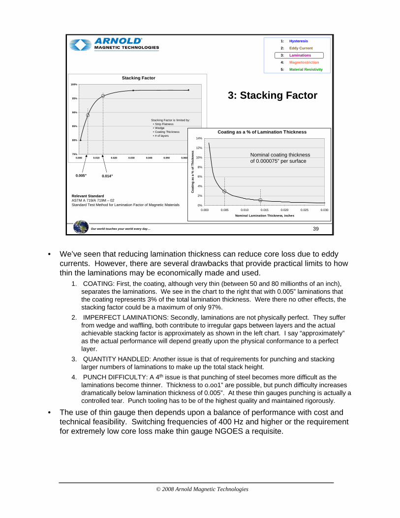
• We’ve seen that reducing lamination thickness can reduce core loss due to eddy currents. However, there are several drawbacks that provide practical limits to how thin the laminations may be economically made and used.
1. COATING: First, the coating, although very thin (between 50 and 80 millionths of an inch), separates the laminations. We see in the chart to the right that with 0.005” laminations that the coating represents 3% of the total lamination thickness. Were there no other effects, the stacking factor could be a maximum of only 97%.
2. IMPERFECT LAMINATIONS: Secondly, laminations are not physically perfect. They suffer from wedge and waffling, both contribute to irregular gaps between layers and the actual achievable stacking factor is approximately as shown in the left chart. I say “approximately”as the actual performance will depend greatly upon the physical conformance to a perfect layer.
3. QUANTITY HANDLED: Another issue is that of requirements for punching and stacking larger numbers of laminations to make up the total stack height.
4. PUNCH DIFFICULTY: A 4th issue is that punching of steel becomes more difficult as the laminations become thinner. Thickness to o.oo1” are possible, but punch difficulty increases dramatically below lamination thickness of 0.005”. At these thin gauges punching is actually a controlled tear. Punch tooling has to be of the highest quality and maintained rigorously.
• The use of thin gauge then depends upon a balance of performance with cost and technical feasibility. Switching frequencies of 400 Hz and higher or the requirement for extremely low core loss make thin gauge NGOES a requisite.
© 2008 Arnold Magnetic Technologies
40Our world touches your world every day…
4: Magnetostriction
Li, Initial Length ΔL, length change in presence of magnetic field
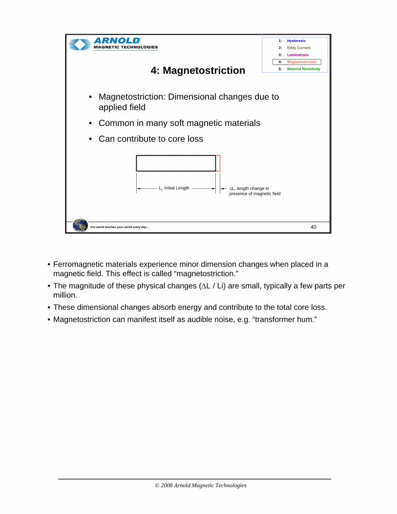
• Magnetostriction: Dimensional changes due to applied field
• Common in many soft magnetic materials
• Can contribute to core loss
Material Resistivity5:
Magnetostriction4:
Laminations3:
Eddy Current2:
Hysteresis1:
• Ferromagnetic materials experience minor dimension changes when placed in a magnetic field. This effect is called “magnetostriction.”
• The magnitude of these physical changes (ΔL / Li) are small, typically a few parts per million.
• These dimensional changes absorb energy and contribute to the total core loss.• Magnetostriction can manifest itself as audible noise, e.g. “transformer hum.”
© 2008 Arnold Magnetic Technologies
41Our world touches your world every day…
4: Magnetostriction of Fe-Si
Pref
erre
d di
rect
ion
Measurement and Characterization of Magnetic Materials, Fausto Fiorillo, p.49
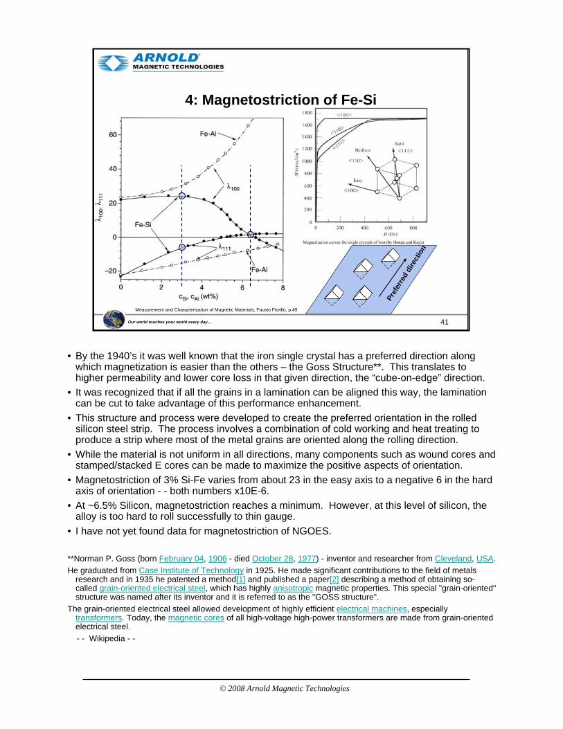
• By the 1940’s it was well known that the iron single crystal has a preferred direction along which magnetization is easier than the others – the Goss Structure**. This translates to higher permeability and lower core loss in that given direction, the “cube-on-edge” direction.
• It was recognized that if all the grains in a lamination can be aligned this way, the lamination can be cut to take advantage of this performance enhancement.
• This structure and process were developed to create the preferred orientation in the rolled silicon steel strip. The process involves a combination of cold working and heat treating to produce a strip where most of the metal grains are oriented along the rolling direction.
• While the material is not uniform in all directions, many components such as wound cores and stamped/stacked E cores can be made to maximize the positive aspects of orientation.
• Magnetostriction of 3% Si-Fe varies from about 23 in the easy axis to a negative 6 in the hard axis of orientation - - both numbers x10E-6.
• At ~6.5% Silicon, magnetostriction reaches a minimum. However, at this level of silicon, the alloy is too hard to roll successfully to thin gauge.
• I have not yet found data for magnetostriction of NGOES.
**Norman P. Goss (born February 04, 1906 - died October 28, 1977) - inventor and researcher from Cleveland, USA.He graduated from Case Institute of Technology in 1925. He made significant contributions to the field of metals
research and in 1935 he patented a method[1] and published a paper[2] describing a method of obtaining so-called grain-oriented electrical steel, which has highly anisotropic magnetic properties. This special "grain-oriented" structure was named after its inventor and it is referred to as the "GOSS structure".
The grain-oriented electrical steel allowed development of highly efficient electrical machines, especially transformers. Today, the magnetic cores of all high-voltage high-power transformers are made from grain-oriented electrical steel.- - Wikipedia - -
© 2008 Arnold Magnetic Technologies
42Our world touches your world every day…
5: IEC Classifications for Soft Magnetic Materials
C21. Isotropic steels
C22. Anisotropic steels
C23. Thin silicon steels
isotropic
anisotropic
isotropic
Non-isotropic
A. Irons
B. Low carbon mild steels
C. Silicon Steels
D. Other steels
E. Nickel-Iron alloys
F. Iron-Cobalt alloys
G. Other Alloys
H. Soft Magnetic Ceramics
Not Classified
C1. Solid material
C2. Flat material
D1. Solid material
D2. Flat material
E1. 72-83 Ni
E2. 54-68 Ni
E3. 45-50 Ni
E4. 35-40 Ni
E5. Approx 30 Ni (temp. compensation)
F1. 47-50 Co
F2. 35 Co
F3. 23-27 Co
G1.Al-Fe alloys
G2. Al-Si-Fe alloys
H1. Soft ferrite
Amorphous metallic glass
Nano-crystalline
Material Resistivity5:
Magnetostriction4:
Laminations3:
Eddy Current2:
Hysteresis1:
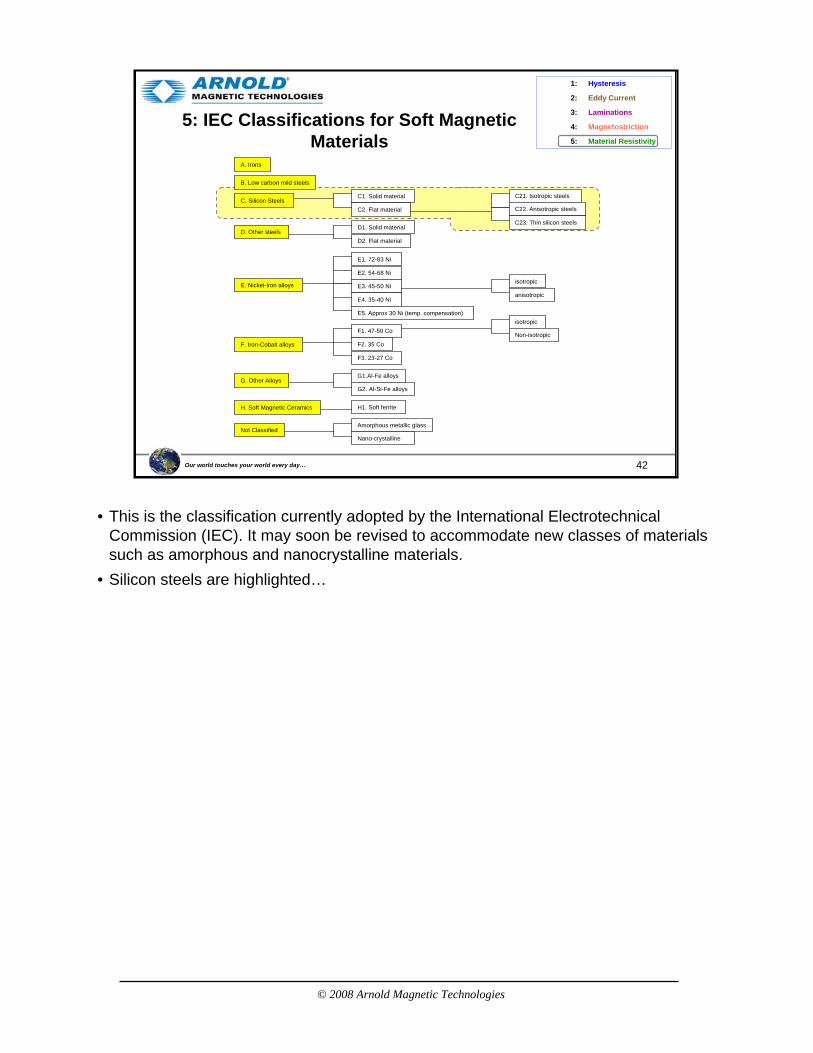
• This is the classification currently adopted by the International Electrotechnical Commission (IEC). It may soon be revised to accommodate new classes of materials such as amorphous and nanocrystalline materials.
• Silicon steels are highlighted…

© 2008 Arnold Magnetic Technologies
43Our world touches your world every day…
5: Material Options & Applications
100 Hz
1 kHz
10 kHz
100 kHz
1 MHz
10 MHz
100 MHz
1 GHz
10GHz
Soft Magnetic MaterialsSoft Magnetic Materials ApplicationsApplications
Cost Per Unit Volume
Si Laminations
Iron Powder
Sendust
Si Tape
50% Ni-Fe Powder
Amorphous
Ni Tape
MPP
Freq
uenc
y
Nanocrystalline
Cobalt Tape
Ni-Zn Ferrite
Mn-Zn Ferrite
IronDC Ni Laminations
Microwave Circulators, Broadband Transformers, Radar, Communication Transceivers
Distribution, Welding and Ferroresonant Transformers, Electromagnetic Ballasts, Power Inductors, Motors, Generators, Relays
Aircraft (400hz) Power Transformers, Resonant Inductors for lighting, Industrial Power Control, Current Transformers
Audio frequency Transformers, Instrumentation Transformers, Telephone Line Interface Transformers for Modems, Speaker Crossover Networks
Railroad Signaling, Audio Transformers, Medical CT & NMR Scanners, Switchmode Power Transformers, Filters, Chokes, UPS , Industrial Control Transformers, Electronic Ballast
EMI & RFI Filters, Broadband Baluns & Transformers for DSL & Modems, ISDN, Flyback Transformers for Televisions & Computer Monitors, Switchmode Power Supplies, Regulators for Battery Powered Devices
Ferrite Antenna Rods, Impedence Matching Transformers, EMI Supression Beads, Cable Shields, Filter Inductors, RF Power Amplifiers, Wireless Communication Equipment
• This chart offers a comparison of soft magnetic materials as a function of cost and usable frequency range.
• Maximum use frequency depends on the operating flux density so the chart should be viewed as a general guide.
• Increasing cost per unit volume is shown from left to right. Performance improvements from a more expensive core material can provide for lower overall system cost.
© 2008 Arnold Magnetic Technologies
44Our world touches your world every day…
5: Comparing Properties
Relative Permeability10 102 103 104 105 106
Bs
(Sat
urat
ion
Indu
ctio
n), k
Gau
ss
0
05
10
15
20
25
30
Co-Fe
FeSi-Fe
36-50% Ni-Fe
Amorphous Alloys
75% Ni-Fe
Fe Powder Cores
Ni-Fe Powder Cores
Soft Ferrites
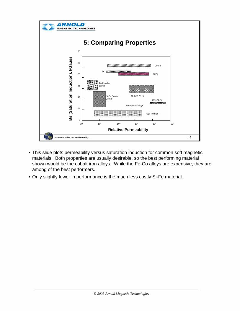
• This slide plots permeability versus saturation induction for common soft magnetic materials. Both properties are usually desirable, so the best performing material shown would be the cobalt iron alloys. While the Fe-Co alloys are expensive, they are among of the best performers.
• Only slightly lower in performance is the much less costly Si-Fe material.
© 2008 Arnold Magnetic Technologies
45Our world touches your world every day…
5: Comparing Properties (Continued)
Soft Magnetic Ferrites
80% Ni
50% Ni
Nickel-Iron Alloys
Iron Silicon-Iron
Cobalt-Iron
Carbon-Steels
Iron Powder Cores
Ni-Fe Powder Cores
Coercivity, Hc (A/cm)0 0.01 0.1 1.0 10.0 100.0
Amorphous
0
1.0
10.0
15.0
20.0
25.0
Bs
(Sat
urat
ion
Indu
ctio
n), k
Gau
ss
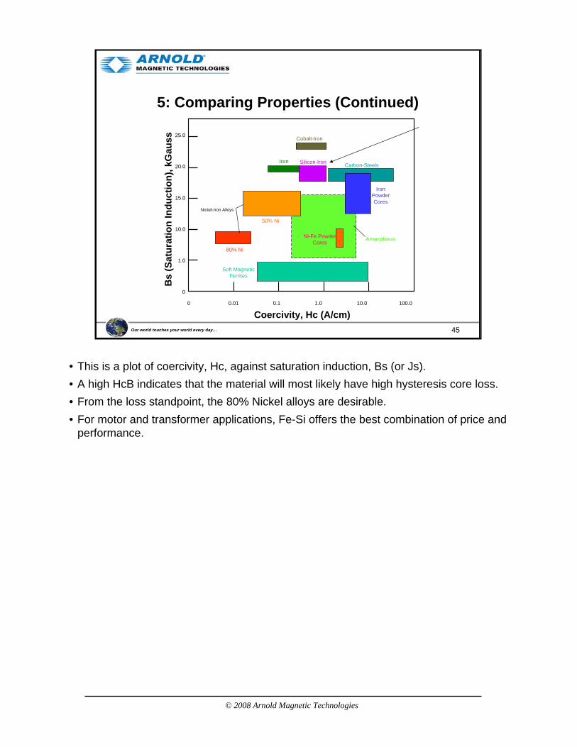
• This is a plot of coercivity, Hc, against saturation induction, Bs (or Js).• A high HcB indicates that the material will most likely have high hysteresis core loss.• From the loss standpoint, the 80% Nickel alloys are desirable.• For motor and transformer applications, Fe-Si offers the best combination of price and
performance.
© 2008 Arnold Magnetic Technologies
46Our world touches your world every day…
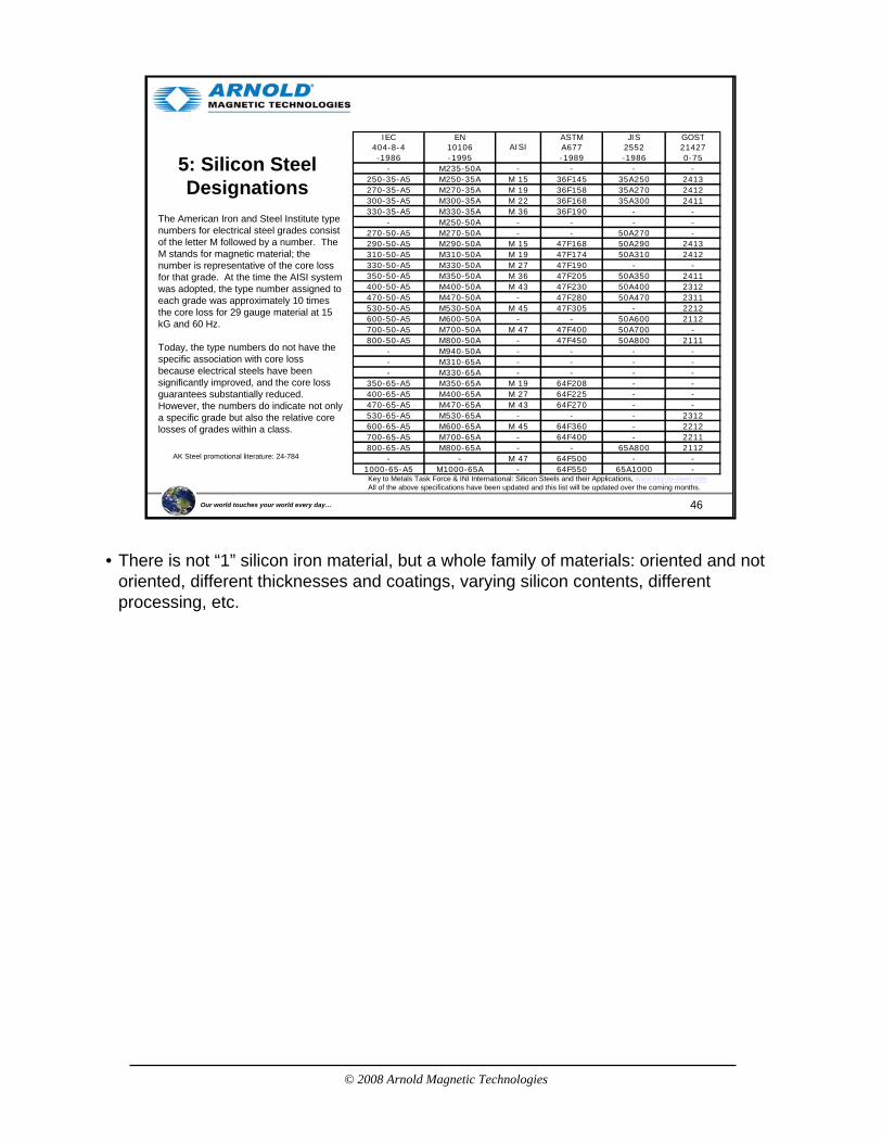
5: Silicon Steel Designations
Key to Metals Task Force & INI International: Silicon Steels and their Applications, www.key-to-steel.comAll of the above specifications have been updated and this list will be updated over the coming months.
IEC EN ASTM JIS GOST404-8-4 10106 A677 2552 21427-1986 -1995 -1989 -1986 0-75
- M235-50A - - - -250-35-A5 M250-35A M 15 36F145 35A250 2413270-35-A5 M270-35A M 19 36F158 35A270 2412300-35-A5 M300-35A M 22 36F168 35A300 2411330-35-A5 M330-35A M 36 36F190 - -
- M250-50A - - - -270-50-A5 M270-50A - - 50A270 -290-50-A5 M290-50A M 15 47F168 50A290 2413310-50-A5 M310-50A M 19 47F174 50A310 2412330-50-A5 M330-50A M 27 47F190 - -350-50-A5 M350-50A M 36 47F205 50A350 2411400-50-A5 M400-50A M 43 47F230 50A400 2312470-50-A5 M470-50A - 47F280 50A470 2311530-50-A5 M530-50A M 45 47F305 - 2212600-50-A5 M600-50A - - 50A600 2112700-50-A5 M700-50A M 47 47F400 50A700 -800-50-A5 M800-50A - 47F450 50A800 2111
- M940-50A - - - -- M310-65A - - - -- M330-65A - - - -
350-65-A5 M350-65A M 19 64F208 - -400-65-A5 M400-65A M 27 64F225 - -470-65-A5 M470-65A M 43 64F270 - -530-65-A5 M530-65A - - - 2312600-65-A5 M600-65A M 45 64F360 - 2212700-65-A5 M700-65A - 64F400 - 2211800-65-A5 M800-65A - - 65A800 2112
- - M 47 64F500 - -1000-65-A5 M1000-65A - 64F550 65A1000 -
AISI
The American Iron and Steel Institute type numbers for electrical steel grades consist of the letter M followed by a number. The M stands for magnetic material; the number is representative of the core loss for that grade. At the time the AISI system was adopted, the type number assigned to each grade was approximately 10 times the core loss for 29 gauge material at 15 kG and 60 Hz.
Today, the type numbers do not have the specific association with core loss because electrical steels have been significantly improved, and the core loss guarantees substantially reduced. However, the numbers do indicate not only a specific grade but also the relative core losses of grades within a class.
AK Steel promotional literature: 24-784
• There is not “1” silicon iron material, but a whole family of materials: oriented and not oriented, different thicknesses and coatings, varying silicon contents, different processing, etc.
© 2008 Arnold Magnetic Technologies
47Our world touches your world every day…
Agenda
• Introduction
• Manufacturing Process
• GOES versus NGOES
• Motor Efficiency
• Loss Factors
• NGO Thin Gauge (Arnon)
• Thin gauge (<=0.007”) Fe-Si is particularly useful for high frequency operation to reduce eddy current loss.
• Oriented product is commonly used in high frequency or burst pulse transformer applications where the benefit of directional properties can be utilized.
• In motors, generators and rotating machinery however, non-oriented Fe-Si is preferred since the field intersects the material at varying angles and benefits from material isotropy.
© 2008 Arnold Magnetic Technologies
48Our world touches your world every day…
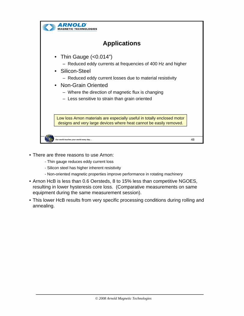
Applications
• Thin Gauge (<0.014”)– Reduced eddy currents at frequencies of 400 Hz and higher
• Silicon-Steel– Reduced eddy current losses due to material resistivity
• Non-Grain Oriented– Where the direction of magnetic flux is changing– Less sensitive to strain than grain oriented
Low loss Arnon materials are especially useful in totally enclosed motor designs and very large devices where heat cannot be easily removed.
• There are three reasons to use Arnon:- Thin gauge reduces eddy current loss- Silicon steel has higher inherent resistivity- Non-oriented magnetic properties improve performance in rotating machinery
• Arnon HcB is less than 0.6 Oersteds, 8 to 15% less than competitive NGOES, resulting in lower hysteresis core loss. (Comparative measurements on same equipment during the same measurement session).
• This lower HcB results from very specific processing conditions during rolling and annealing.
© 2008 Arnold Magnetic Technologies
49Our world touches your world every day…
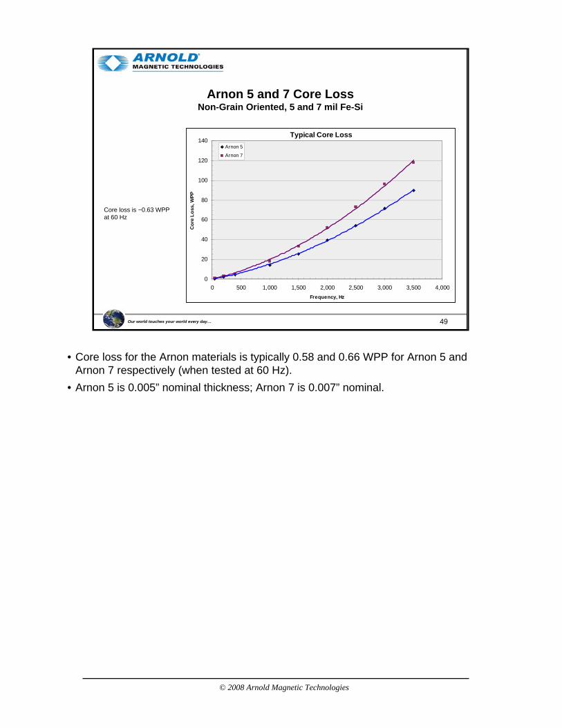
Arnon 5 and 7 Core LossNon-Grain Oriented, 5 and 7 mil Fe-Si
Typical Core Loss
0
20
40
60
80
100
120
140
0 500 1,000 1,500 2,000 2,500 3,000 3,500 4,000Frequency, Hz
Cor
e Lo
ss, W
PP
Arnon 5
Arnon 7
Core loss is ~0.63 WPP at 60 Hz
• Core loss for the Arnon materials is typically 0.58 and 0.66 WPP for Arnon 5 and Arnon 7 respectively (when tested at 60 Hz).
• Arnon 5 is 0.005” nominal thickness; Arnon 7 is 0.007” nominal.
© 2008 Arnold Magnetic Technologies
50Our world touches your world every day…
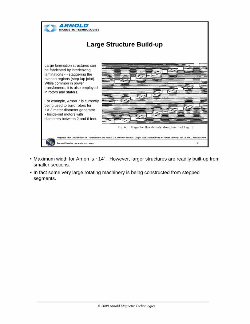
Large Structure Build-up
Large lamination structures can be fabricated by interleaving laminations - - staggering the overlap regions (step-lap joint). While common in power transformers, it is also employed in rotors and stators.
For example, Arnon 7 is currently being used to build rotors for:• A 3 meter diameter generator• Inside-out motors with diameters between 2 and 6 feet.
Magnetic Flux Distributions in Transformer Core Joints, G.F. Mechler and R.S. Girgis, IEEE Transactions on Power Delivery, Vol.15, No.1, January 2000
• Maximum width for Arnon is ~14”. However, larger structures are readily built-up from smaller sections.
• In fact some very large rotating machinery is being constructed from stepped segments.
© 2008 Arnold Magnetic Technologies
51Our world touches your world every day…
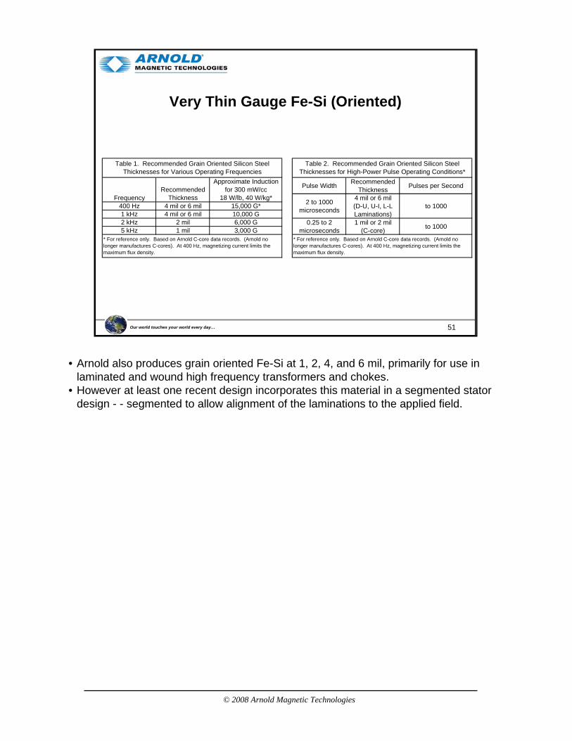
Very Thin Gauge Fe-Si (Oriented)
FrequencyRecommended
Thickness
Approximate Inductionfor 300 mW/cc
18 W/lb, 40 W/kg*400 Hz 4 mil or 6 mil 15,000 G*1 kHz 4 mil or 6 mil 10,000 G2 kHz 2 mil 6,000 G5 kHz 1 mil 3,000 G
Table 1. Recommended Grain Oriented Silicon Steel Thicknesses for Various Operating Frequencies
* For reference only. Based on Arnold C-core data records. (Arnold no longer manufactures C-cores). At 400 Hz, magnetizing current limits the maximum flux density.
Pulse Width RecommendedThickness Pulses per Second
2 to 1000microseconds
4 mil or 6 mil(D-U, U-I, L-LLaminations)
to 1000
0.25 to 2microseconds
1 mil or 2 mil(C-core) to 1000
Table 2. Recommended Grain Oriented Silicon Steel Thicknesses for High-Power Pulse Operating Conditions*
* For reference only. Based on Arnold C-core data records. (Arnold no longer manufactures C-cores). At 400 Hz, magnetizing current limits the maximum flux density.
• Arnold also produces grain oriented Fe-Si at 1, 2, 4, and 6 mil, primarily for use in laminated and wound high frequency transformers and chokes.
• However at least one recent design incorporates this material in a segmented stator design - - segmented to allow alignment of the laminations to the applied field.

© 2008 Arnold Magnetic Technologies
52Our world touches your world every day…
An Example: Small Motor Comparison
Existing Design5 HP (Motor + Gearbox)• Torque Varies• Speed adjusted with Gearbox, not motor• Efficiency Varies• Max Efficiency for Speed range 72%• Overall Weight: 266lbs
New 5+ HP EVT Motor(Direct Drive)• Consistent Torque• Speed adjusted at motor, precisely• Efficiency remains consistent• Max Efficiency for Speed range 97%• Overall Weight: 200lbs
Courtesy EVT LLC, www.evtllc.com
• The challenge: to replace an open type motor and gear box with a totally sealed motor without gear box while improving on the linearity of torque and raising the efficiency.
© 2008 Arnold Magnetic Technologies
53Our world touches your world every day…
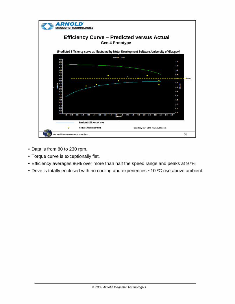
Efficiency Curve – Predicted versus ActualGen 4 Prototype
(Predicted Efficiency curve as illustrated by Motor Development Software, University of Glasgow)
Predicted Efficiency Curve
Actual Efficiency Points Courtesy EVT LLC, www.evtllc.com
96%
• Data is from 80 to 230 rpm.• Torque curve is exceptionally flat.• Efficiency averages 96% over more than half the speed range and peaks at 97%• Drive is totally enclosed with no cooling and experiences ~10 ºC rise above ambient.
© 2008 Arnold Magnetic Technologies
54Our world touches your world every day…
References
• Ferromagnetism, Richard M. Bozorth, IEEE Press, 1993
• Measurement and Characterization of Magnetic Materials, Fausto Fiorillo, Elsevier Academic Press, 2004
• Handbook of Small Electric Motors, William H. Yeadon and Alan W. Yeadon, McGraw-Hill, 2001
• Handbook of Electromagnetic Materials, Perambur S. Neelakanta, CRC Press, 1995
• Electrical Materials Handbook, Allegheny Ludlum Steel Corp., 1961
• Handbook of transformer Design & Applications, William M. Flanagan, McGraw-Hill, 1992
• Applications of Magnetism, J.K. Watson, Storter Printing, 1985
• Proto Laminations Website (www.protolam.com)
• Lamination Steels CD-ROM, EMERF
• Silicon Steels and Their Applications (www.key-to-steel.com/DE/DE/Articles/Art101.htm)
• Hyperphysics (http://hyperphysics.phy-astr.gsu.edu/hbase/HFrame.html)
• Wikipedia (www.wikipedia.org)
• All of these were useful, but the three in dark blue were excellent.
© 2008 Arnold Magnetic Technologies
55Our world touches your world every day…
Thank you !
FEA from Permanent Magnet Motor Technology: Design and Applications, Jacek Gieras and Mitchell Wing, p.200