designorrree standingwalls · the brick development association information notes prepared in...
TRANSCRIPT

J. O. A. KORFF BSc CEng FIStructE MICE
DESIGNOrrREESTANDINGWALLS
e l/SfS' (21) ' F ',
February 1984


THE
BRICKDEVELOPMENTASSOCIATION
Information notes prepared in August 1995 relevant to
DESIGN OF FREESTANDING WALLSBy J . O. A. Korff
BDA Design Guide 12, February 1984
Introduction
The Des ign of Freestanding Walls DG12 was firstpublished by BDA in February 1983 and subsequentlyrevised and reprinted in February 1984. Due to itspopularity with designers and because much of theguidance is still relevant , DG12 is being retained in theBDA's Publications List.
Codes, Standards and other reference material havechanged during the intervening 12 years since the guidewas reprinted in 1984, and the purpose of theseinformation notes is to highlight those importantreference changes which have a significant influenceon the use of the guide. These updated references willneed to be fully considered by designers in theinterpretation and use of DG12.
It is not possible to issue a teJduralline-by-line addendumsheet to the guide and no attempt is being made to dothis . In due course when all the essential Codes,Standards and other reference sources which arecurrently changing have come into effect, it is theAssociation's intention to completely revise DG12.
Design for Exposure/Dura b il ity
Pages 4 to 8 inclusive of DG12 provide advice onexposure , durability and associated detailingconsiderations for the des ign of freestanding walls .Some of this guidance has been superseded by moreup-to-date information and reference material. The
"special" and "ordinary" qualities classification of claybricks is now redundant and has been superseded.
Reference should be made to BS 39211'), BS 187(2),BS 4729(3) and BS 6649 (1 3) and to BS 5628:Use of
Masonry:Part 3:1985:Materi als and components ,design and workmansh ip(14). Those clauses of BS5628:Part 3:1985 which are of particu lar relevance tobrickwork masonry are : Clause 21 - Exclusion ofMo istu re (sub-clauses 21.2 and 21.7), Clause 22 Durability, Clause 23 - Selection of Mortars, and Table13 - Durability of Masonry in Finished Construction.
A further source of information regarding durability ofbrick masonry construction is BDA Design Note 7 Brickwork Durab ility(15).
W ind Load s
DG12 derives wind loadings in accordance with BSCP3:Chapter V:Part 2:1972:Wind Loads. At the presenttime this Code is still relevant to wind loading derivation ,although the current version has been amended fromthe 1972 edition. Consequently figure 3 on page 11 ofDG12 - Bas ic wind speed In mls requires revising inaccordance with the latest amendment of CP3.
During 1995 it is expected that BS 6399:Loadi ng fo rBulld ings:Part 2: 1995 :Code of pract ice for windload s, will be published by the British StandardsInstitution. This new wind load code will be a completerevision of CP3. BS 6399:Part 2 is likely to coexistalongside CP3:Chapter V:Part 2 for about 12 months,after which time CP3 will be withdrawn. BS 6399:Part2 will contain specific information for the derivation ofwind loads on freesta nding walls .
DG12 can be used in either the context of CP3:ChapterV:Part 2 or BS 6399:Part 2. If wind loading derivation isin accordance with BS 6399:Part 2 then Table 2 (page12) of DG12 becomes redundant whilst Figure 7 (page18) of DG12 continues to be relevant if "p., the designwind pressure is derived fully in accordance with BS6399:Part 2 and incorporates the appropriate partialfactor of safety for loading (YI) from BS 5628 (usually YI= 1.2). This latter requirement also applies to DG12guidance in respect of the use of "p". the design windpressure, referenced on pages 17, 18, 19,20,21 and23 for unreinforced brickwork des ign and to similardesign wind pressure references for re inforcedbrickwork, (pages 26 to 34 inclusive of DG12).
Structural Masonry Design Codes
All references in DG12 to BS 5628:Use of Masonry:
Part 1:1978:St ructural use of unrelnforced masonry,should be replaced by reference to BS 5628:Use ofMasonry:Part 1:1992:St ructural use of unreinforcedmasonry. For brickwork freestanding wall design toDG12 the 1992 version of BS 5628 :Part 1 is identical tothe 1978 edition with the exception that the characteristicshear strength of unreinforced masonry in designationiii) mortar is reduced to 0.15 N/mm2 (from 0.35 N/mm2 ) .
Page 21 of DG12 shows a shear strength calculationfor piers and if the revised characteristic shear strength

of 0.15 N/mm2 is taken into account the pier designdemonstrated remains adequate.
Pages 26 to 34 inclusive of DG12 demonstratereinforced brickwork design using two alternativemethods. The first is a permissiblestressdesign methodbased on CP 111 :Part 2:1970, while the second is limitstates based to SP91. Reference to SP91 should bereplaced by BS 5628 :Use of Masonry:Part2:1985:Structural use of reinforced and prestressedmasonry. BS5628:Part2 becameavailableafter DG12was published. The detailed design approach andworked examples for limit states design shown in DG12from pages 29 to 34 inclusive need to be modified inrespect of the recommendations of BS 5628: Part2:1985, although the basic principles of reinforcedmasonry design using this Code remain the same asthose given in SP91 . SP91 was a forerunner to BS5628:Part 2.
An amended version of BS 5628:Part 2 is expected tobe published in the Autumn of 1995. Upon publicationby the British Standards Institution this Code should besubstituted for the 1985 edition. Major changes willinclude guidance on design for durability of reinforcingsteels (cover and infill concrete quality) and changes todesign methods for laterally loaded masonry panelsincorporating bed-joint reinforcement. References willalso be brought fully up-to-date.
References
The list of references on page 35 of DG12 should beamended as follows (others not amended remaincurrent):
(1) BS 3921 :1985. Specification for clay bricks.British Standards Institution.
Note that in due course CP3:Chapter V:Part 2is likely to be withdrawn.
(10) BS 5628:Use of Masonry:Part 1:1992:Structural use of unreinforced masonry.British Standards Institution.
(12) Replace reference to SP91 :1977 by:BS5628:Use of Masonry:Part 2:1985:Structuraluse of reinforced and prestressed masonry.British Standards Institution.
Note that in due course BS 5628:Part 2:1995 willsupersede BS 5628:Part 2:1985.
Add new references:
(13) BS 6649:1985. Specification for clay andcalcium silicate modular bricks. BritishStandards Institution.
(14) BS 5628 :Use of Masonry:Part 3:1985:Materials and components, design andworkmanship. British Standards Institution.
(15) J R Harding & R A Smith. Design Note 7 •Brickwork Durability. 1986. BOA.
(16) M Hammell & J Morton. The Design of CurvedBrickwork. 1991 . BOA.
(17) B A Haseltine & J N Tull. Handbook to BS5628:Part 2:Section 1:Background andMaterials. 1991. BOA.
(18) B A Haseltine & J N Tull . Handbook to BS5628:Part 2:Section 2:Reinforced MasonryDesign. 1992. BOA.
(3)
(4)
(6)
BS 4729:1990. Specification for dimensionsof bricks of special shapes and sizes . BritishStandards Institution.
Delete reference to BS 3798:1964 which is awithdrawn standard and add in its place:
BS 5642:Sills and Copings:Part 2:1983:Specification for copings of precastconcrete, cast stone, clayware, slate andnatural stone. British Standards Institution.
Add additional reference to BS 6399:Loadingfor Buildings:Part 2:1995:Code of practicefor wind loads, when available from the BritishStandards Institution.
The following two references may be of interest andare published by BRE. They are compatible with DG12and its recommendations.
(19) Good Building Guide 14. Building SimplePlan Brick or Blockwork Freestanding Walls.Revised May 1994. Building ResearchEstablishment.
(20) Good BUilding Guide 19. BUildingReinforced, Diaphragm and Wide PlanFreestanding Walls. March 1994. BuildingResearch Establishment.
August 1995e Brick Development Association Limited

First p ublished February 1983Revised and reprinted February 1984(see Editor's Note opposite)
Edited by J.Morton liSe PhD CEng M ICE l\lInstM
Designoffl'ee slandingwallsJ. o. A. KORFF BSc CEng FIStructE MICEDeputy Structural Engineer. OLC Department of Ar chi tecture and Civic Design
The Brick Development Association1

INTRODUCTION I
This document. which has been pre pared for the guidance of civil and structura l engineers. architects andbuilders. deals with the design and use of plain and reinforced free-sta nding brick walls not forming partof a building.
Free-standing brick walls are widely used for bou nda ry demarcation. landscaping. screening. secur ity.and noise barriers. When properly constr ucted . free-stan ding br ick walls have proved to be extremelydurable a nd pleasing in appearance. There are many examples of brick walls. hundreds of years old .which apart from occasiona l point ing and a tte ntion to coping req uire no other maintenance. Bymodern sta ndards. most of these old walls. bu ilt by rule of thumb. are clearly over-des igned.
However. since the turn of the century. and part icula rly after the Second World War. financia lcon straint s and the phenomenal gro wth of mass hou sing estates produced some very unsat isfactoryexamples offree-sta nding wallin g. Strange as it may seem. walls are not subjected to statutory control .except in the Inner Lond on Area where app rova l is requ ired when the height exceeds 1.83 m (6 ft )above gro und level. It is. therefore. not surprising that in the major ity ofcases walls a re put up ratherthan designed. and all too frequently prematurely deter iorate or blow over.
In most cases. a durable and stable wall will cost little more than a sub-sta ndard one. All that isrequired is the selection of suitable mater ials co mbined with an efficient arrangement of brickwork.
I & 2 Free-standing wall screening a small mews development and reducing noise from a )'ery husy trunk road.
2

3 Staggered boundary wall enhances the roadside.
Desig n (Iffree slanc/in.ttwalls 3

FACTORS AFFECTING DESIGN ANDCONSTRUCTION
EXPOSUREMore often than not . free-standing walls are exposed to the full effects of the weather. Th e action ofwind. as a late ral force. is ca tered for by the strength design. But. the combined effect of rain anddr iving wind requ ires the use of suitable materials and correct const ructiona l det ails.
Figure I shows the driving rai n index ma p of the United Kingdom which. at present . is the best publi shedguide to the severity of weather condit ion s. In genera l. bricks for free-standing walls in the moderate andsheltered zones should comply with the frost resistanc e requirement s (but not necessarily the otherrequirements) for special quality brick s. However. where the wall is properly weathered (ie provided withan overhanging coping) ordina ry quality brick s may be used if recommended by the manufacturers for theparticular circumsta nces. In a reas of severe expos ure. special qualit y bricks to BS 3921 ( n . or other brickshaving a high frost resistance, are recommended. Calcium silicate bricks Class 3 or st ro nger. inaccordance with BS 187.'" a re suita ble for a ll degrees ofexpos ure.
These are very general guide lines which may be mod ified in the light oflocal conditions. Users sho uldco ntac t the manufacturers to confirm tha t thei r bricks are suita ble for the intended degree of expos ure.
It is also well worth while to exa mine existing walls in the neighbourhood and note the perfo rmance ofparticular bricks after a few winte rs' service . The exposure of saturated bricks to frost or. even moreimportantly. to the freeze/th aw cycle ove r severa l winters gives a very useful guide to durabil ity.
Some of the more econom ical walls recommended in this guide incorpo rate half-brick pan els. Th esewalls a re particularl y vulnera ble to saturation in the winter months. but should perform satisfacto rilyprovided they are con structed in accorda nce with the advice given in this guide and under competentsupervision.
COPINGS AND CAPPINGSThe function of copings and ca ppings is aesthetic as well as pro tective. Th e appea rance of a wall may bedram atically changed by altering the coping or capping.
Th e protective function is aga inst vertica l water pene tra tion and in sheddi ng rainwater clear of the faceas effectively as poss ible. The idea l copi ng sho uld be durabl e. waterproo f. weather the brickwork. andcon structed preferably with interlocking units. Th e ove rha ng sho uld include a th roating recess or a dripnot less than 13 mm wide. with the outer dri p edge at least 40 mm from the face of the brickwork assho wn in Figure 2e. Different shapes and types ofcopings and ca ppings a re shown in Figure 2.
For cappings of special brick shapes. reference should be mad e to BS 4729.,,, and for copings ofclayware,concrete or stone. to BS 3798.... A minimum weight of 1.5 kN /m ' is preferred for copings with concreteor stone unit s. Some brick manufacturers can supply the ir own capping system which incorporates a dpc.
In many instances. for aesthetic or functi onal reasons. it is necessary to use a brick-on-edge capping.Such a capping will perform reasonabl y well. provided that it is co nst ructed in accordance with therecommendation s of Table I. Suit abl e galvanised stee l. stai nless steel or non-ferrou s metal anchors
4

1Driving rain index
4
3
2
o
L:";«;',,,I severe
1>::» ::»1 moderate
1 1sheltered
2
NF
NB
3 4
HY
! a
7
TG
5

may be used to prevent movement s of end unit s, Figure 2n. For best result s an overhang such as shownin Figure 2 (f-i) should be provided.
MORTARSFree-stand ing walls derive part of their resistance to lateral forces from their flexural strength. Whereadhesion between bricks and mort ar is not achieved, or is lost due to deterioration of the mortar, thestrength may be reduced by as much as 50%. It is therefore imperative to ensure permanent flexuraltensile adhesion between the bricks and the mortar.
Th ere is some evidence that the presence of entrained air bubbles, due to the use of plasticisers, resultsin an inferior adhesion. Experience shows that plasticised or masonry cement mort ars may be perfectlyworkable when the cement content is as low as a half or a third of that specifi ed. Thus, a visual checkon mortar workability cannot indicate whether it has been correctly gauged.
The following recommendations should ensure adeq uate and durable adhesion between bricks andmortar :(1) Cement/lime/sand or cement/sand morta rs should be used. Plasticised or masonry cement mort arsare not recomm ended, but may be used with the permission of the engineer and under closesupervision aimed at ensuring that:(a) the mortar is correctly gauged with adequate water content(b) mixing is strictly controlled to prevent excessive air entrainment
(c) part ially set mort ar (normally after two hours) is d iscard ed and not reconst ituted
(d) the suction rate of unit s is adjusted by controlled wetting.
In general, air-entrained mortars are much more prone to site abuse, and circumstances may arisewhere adequate adhesion is not achieved.
(2) In dry , hot weather, bricks should be wetted by lightly spraying stacks or docking individual units.Alternatively, a wetter mort ar may be used.
(3) Where bricks conta in sulphates in excess of 0.5% (ie, where bricks do not conform to the maximumallowable soluble sulphate content for special qua lity bricks to BS 3921) sulphate resisting Portland
2a 2b
castconcretea stone copingStoas3798. copings witharrinirnm",..;g,lof 1.5kNJm' are~red
2 courses of s1ates.-<~~~~~10 BS 743. 1U1y halflapped ard beddedin 1:14. :3 mortar
. 0 •
' 0 •
•toundahon
dpc 2 c:o..<sesofbridIs .,BS3921 &743havrog~
not exceeding 7%. in1: ~ : 3 morlar .t.;~===:;r::~~.....~--
6

dpc toformdrip
----2c 2d
•dPCtoform--~~i"'75i==75i==9'!"'"drip
2e 21 2g
(j .," .
copingb -ees 10854729
dpc toformdrip ~
~~~
., ...',"iiEO
.'; '9'
q,.:..'n,:;;.· ' ;,, '~' "~ ." ..
attemative sector-cioorsectco petered
2hbrick on edge in1:l4;3 mortar.and 2 cou rsestile creasilg
2i 2 courses tilecreasingwithcross joints ardridge tile in1:14 :3 mortar
7
d PC ~
2n 215x215x102.5soc erd petered
non-ferrousor galvarised (without c
~cra~..< " ",,: ._ .."..",-,
brick_capping above dpc tobe speciat QUalrty n t :~ : 3 mortar;or class4 calciLmsilicate bricks in 1)~:4~ mortar.see text and lable1 for walland foundations brickwork.andrroverTB"lt joint requirements
2mp1inthstretdler
2k 21cut br1ck on end bull-nosed doUJIe
stretcher on flat
dpctofomjdrip
2coorsesrrinrronaboe dpc
brickonedgecapping2cocrses
dpC toformdrip--~~l!o;~!":#t--_...t..rrinrron
2j
aJtemati've shape
Design offree standing walls

TaM. 1 Brick and mortar requirements and associated materials
Position in wall Bricks Mortar OPC Remark sFo undat ions 10 Clay to 1:1 :3 SRPC ifsulphates Not esse ntial with No other formof150mm above BS3921 in brick or soil, low abso rption dpc sho uld be used.ground level ( fro st ot herwise 1:1:3 PC bricks, but if un less allowed for in
res istant), Where in dou bt desired pro vide two structural design.Calc ium sulphate resisti ng coursesof bricksSilicate cement should be having absorptionClass 3 10 used of not more than 7%.BSI87 or two courses of slates
to BS743 fully half-lapped and bedded inmortar
From 150mm Clay to M inimum 1:1 :6or I :1:3a nd I :1:41 areabove ground BS3921 1:1:4ISRPCif more durablelevel to u/s sulphates in bricks inof coping excess ero.s%
otherwise 1:1:6or1:1:41 PC
Calcium l:l :6PCSilicateClass 310BSI87
Coping or Clay Special 1:1:3 PCCapping Quality to
BS3921 Flexible dpc to BS473 To improve water-below coping or proofingof coping
Calcium 1:1:4IPC capping. Preferably aluminium stearateSilicate Permagrip additive may be usedClass 4 10BSI87
cement (SRPC) sho uld be specifi ed and the mortar strength mu st not be weaker than I : I :6. In cases ornear maximum permitted sulphate conten t and/o r severe exposure I :! :4!, or even 1: 1:3 SRPC, ispreferable - see Table I.
DAMP PROOF COURSESThe strength of unreinforced free-standing walls described in thi s guide is dependent on their flexuralten sile stress. Consequently, the use or any dpc near gro und level incapable or providing the necessaryadhesion across the joint is not permitted unless the ' No Tension - method or design is used , as explainedin 'Methods or Design' (page 20).
In practice. the only dpcs which meet thi s requiremenl are :
(a) two courses or (engineering) brick s to BS 3921 or BS 743"! For free -standing wall s. specia l qu al itybricks with a water ab sorption or not more than 7% are considered to be adequate;
(b) two courses or slates fully half lapped and bedded in mortar to BS 743.
In both cases. 1:1:3 PC or SRPC mortar (as appropriate) sho uld be used . However, in many cases wherewalls are constructed of fro st-resistant brick s, the need for a dpc near ground level is questionable.
Below the coping or ca pping, a suitable flexible dpc should be provided, fully bedded on the undersideand on top in a suita ble mortar (see Table I) an d project ing 10 to 15 mm from the race to form a drip.Permagrip dpc is part icularly suitable for this purpose beca use or its superior adhesion to mortar.Flexible dpc's must never be cut back or poi nted over.
MOVEMENT JOINTSIn common with other building materials. brickwork is not dimensionally stable, and both reversibleand irreversible changes occur. In the case of free sta nding walls. the following main factors must betaken into account in deciding the frequency or movement joints :
(1) moisture expansion orclay brick s
(2) thermal expansion or contraction
t3) drying shrinkage, applicable in practice to calcium silicate br icks only.
Movement joints sho uld be con structed so that , in effect . they int roduce a complete separation over the8

j--._....~-~-:...:--
4.5& 6 Correctly d<'siglU'c/ II/(H', 'I1 1('1I1 joints.
9
7 & 8 Cappings carried across movement joints , Though anewly constructed ....·011. the b('gi" "illKS of potential problems{IN! already apparent,

full height of the wall , including the dpc and coping or ca pping but not the foundations. Detailedrecommendation s for the design of movement joints a re given in Sect ion 3.
FOUNDATIONSThe foundat ion requirements for free- standing walls may be less onerous than th ose for buildings.
It is suggested that , for free-standing wall s not fo rm ing part of a build ing a nd not exceeding 2.~ m inheight, a foundati on depth 01'0.5 rn, on a sufficiently firm bottom in any type of so il, provides areason able co mpromise between cost conside ra tions an d stability. For higher wall s in cohesive so ils, aminimum 01'0.75 m is recommended. Wh ere mixed mad e-up gro und is pre sent, it would be reasonableto assume an allowable net bearing pressure of 50 kN /m ' , pro vided no organic so il is pre sent and areasonable degree of con solidation has been attained over the yea rs.
Fresh fill is not suitable for an y foundation s unle ss mech anically compacted in thin layers. I n suchconditions, the allowable net bearing pre ssure should, however, be limited to 25 kN /m ' and the footingsshould be rein forced.
For reason s explained on page 17 , the depth of brickwork below ground ought not to exceed 200 mm .Deta iled reco mmenda tions in respect of founda tions for various walls, a nd worked examples, a reprovided in Sect ion 3.
WIND LOADSThe design wind speed V. is calculat ed on the basis ofCP 3, C ha pter V, Part 2''':V, =VS,S,S3whereV = ba sic wind speed in m/sec (see Figure 3)S , = topographic fact or. normally taken as IS, = gro und roughness. size of st ructure and height facto r. 0.6 va lue a pplies to wall s of any length not
exceeding 3 m height a bov e ground level, located in the co unt ry with many wind breaks, sma lltowns or outskirts of large citi es.
S3 = statistica l factor ta ken as I in all circumstances.Therefore,V. = 0.6V m/sec.
Since th e limit state approa ch is adopted. the design wind speed is redesignated V" th e cha racte risticwind speed, but note tha t V. = V, =0.6V. T he design wind pressure ca n now be ca lculat ed :p = KV. 'C,y, N/m 'wherep = design wind pressure, N/m'K = 0.613 universal coefficient from the wind codeC, =force coefficient, assumed 1.2Yr = partial safety fact or for laterally loaded free-stand ing walls = 1.2.Therefore,p = 0.613 x (0.6V) , x 1.2 x 1.2
= 0.318V' N/m 'For other S , and S , factors, the formula may be written in a more genera l form :p = 0.88 (S, x S, x V)' .
No guidance is given in CP 3, Ch apter V, Part 2 co ncerning the appropria te force coefficient forfree-standing walls but, in the Wind loading handbook '" the authors suggest that such wa lls should betreated as mem bers ofa n unclad st ructu re. A table is provided in the handbook , covering differentca ses and showing the force coefficient varying between 1.2 a nd 2.
However , if th e cases shown a re related to the act ua l configura tio n of bounda ry walls, it becomes clearthat a coefficient ofless than 2 ha rdl y eve r a pplies. Th e co ntention that a force coefficient of 2 isexceptionally high , a nd does not accord with the history of service beh av iour of garden wall s, may bebest illustrated by the fact th at. until 1973, such walls in the a rea covered by the a l C By-laws weredesigned to 6Ib/ft ' (290 N/m ' ). Th e current practice in th e Gl.C is to use Cr= 1.2 which produces8Ib/ft' (380 N/m '), a 33 % increase. But , if Cr= 2, as suggested by the handbook. is assumed, the wallswill have to be designed to with stand 13 Ib/ft ' (636 N/m ') - und oubtedly a very unreasonable proposition .
The formula derived above, p = 0.318V' , a pplies to gro und rou ghn ess Ca tego ry 3 which is defined as:'Country with many windbreaks (hedges, copses, o rcha rds, ro ws of trees, o r simila r), sma ll towns oroutskirts of large citie s' . This formula is likely to be appropr iate in the majority of cases but, in the10

3
Basicwind speeds in m/s
HY/ J./~
NF I \1~~17 f <j;; NJ _~K() IS,~ _ ! ~ J" 48
,..'0 0 A~rdeen , r.,.·...
Kilometreso 20 60 100 140I I I ! ! , , ! !
I iii io 20 40 60 80 100St atute miles
II

open country with only scattered wind breaks (Category 2), equ ation p = 0.396V' should be used. Wherethere a re no windbreaks at all in open country (Category I), p = 0.537V' applies.
The relevant value s ofdesign wind pressure are given in Table 2. It should be noted that the correc tassessment of gro und roughness ca tegory is important because it makes an appreciable difference to thedesign pressure. When in doubt, a higher category should be used. In unusua l circ umstances, when wallsare constructed on very exposed hill slopes and crests where aocelerat ion of wind is known to occur, or invalleys shaped to produce funnelling effects, the values of pre ssure given in Table 2, should be increasedby 20% . The existence of these unusual local effects sho uld be checked with the nearest meteorologicaloffice.
TaM, 2 Design wind pressure for walls ofany Im /(th not ex ceeding J m in height" (abov ground 1..,0
Basic Ground roughness Categor)· 3 Category 2 Open country Ca tegory 1 Open countryWind Country with many windbreaks, with scattered windbreaks with no obstructionsspeed small towns, outskirts of large cities p N/m' p N/m'V mrsec p N/m'
38 459 572 77540 509 634 85942 561 699 94744 61 6 767 104046 673 838 113648 733 912 123750 795 990 134352 860 1071 145254 927 1155 156656 997 1242 1684
»For walls between 3 & 4 m in height the values of the design wind pressure given in Table I should be increased by 5)0/0and for walls between 4 & .'5 m the values in Table 2 should be increased by 20%
9
---•
......- .~ -Jr._
:::-- - :- -~ ~ ... . -- -12
10
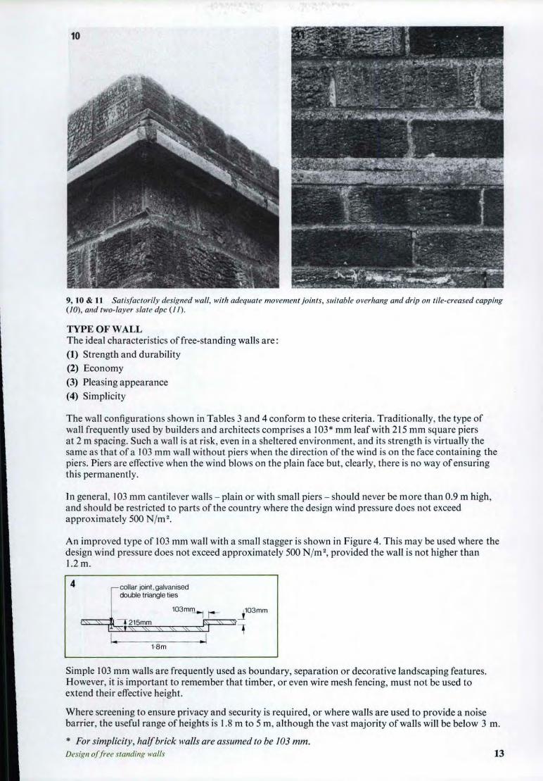
9, 10 & 11 Sa tisfac torily designed wall, with adequate movement joints, suitable overhang and drip 01/ tile-creased capping(/0 ), and two-layer slate dpc (II) .
TYPE OF WALLThe ideal cha racteristics of free-standing walls a re :
(1) Strength and durability
(2) Economy
(3) Pleasing appea rance
(4) Simplicity
The wall co nfiguratio ns show n in Tables 3 and 4 conform to these criteria. Tradit ionall y, the type ofwall frequently used by bu ilders and architects comprises a 103* mm leaf with 215 mm square piersat 2 m spac ing. Such a wall is at risk, even in a sheltered environment, and its strength is virtua lly thesame as that of a 103 mm wall without piers when the direction of the wind is on the face conta ining thepiers. Piers arc effective when the wind blows on the plain face but , clearly, there is no way of ensuringthis permanently.
In genera l, 103 mm cant ilever walls - plain or with small piers - should never be more than 0.9 m high,and sho uld be restricted to parts of the co untry where the design wind pressure does not exceedappro ximately 500 Nfm' .
An imp roved type of 103 mm wall with a sma ll stagge r is show n in Figure 4. This may be used where thedesign wind pressure does not exceed approximately 500 Nfm ', provided the wall is not higher than1.2m.
13
I
l03m~ ,._
, collar joint.qalvaniseddouble triangle ties
tam
4
Simple 103 mm walls a re frequ ently used as boundary, separation or decorative landscaping features.However, it is important to remember that timber, or even wire mesh fencing, must not be used toextend their effective height.
Where screening to ensure privacy and security is required, or where walls a re used to provide a noisebarrier, the useful range of height s is 1.8 m to 5 m, altho ugh the vast majority of walls will be below 3 m.
* For simplicity, halfbrick walls are assumed to be 103 mm.Design offr ee standing walls

Fo r walls higher than 5 m, diaphragm wall construction may be more economical. Thi s is dealt with inother BDA pub lication s'" 9} .
Table 3 shows walls of the same order of strength as a 215 mm solid wall. The efficiency number is. b 100 x section modulus m' d i d d . di h i ' I hgiven y . an IS mten e to in reate t e re anon between f1 exura strengt
cross-sectional area m 2
and the volume of materials used. The higher the number, the more efficient the configu ration.
Table 4 shows walls of the same order of strength as a 328 mm solid wall which can be used for a heightof about 3 m. Above this height consideration should be given to the use of reinforced masonry, which islikely to be more economical.
However, if an unreinforced wall is preferred, the configuration shown in Figure 5, which has an averageZ value of 3.0 x IO-'m ' per m run , is suitable for height s 3.5 to 4.5 m.
It is not recommended that walls above 3 m high should be constructed without advice from anengineer or other appropriately qualified person . Man y factors vitally affecting the strength may be quiteinadvertently overlooked by the architect or the contractor, and the consequences of a failure ofa highwall could be very serious to life and property. When dealing with high ,expensive walls, the selectio n ofa suitable configuration should be the subject ofa close consultation between the architect, the quantitysurveyo r, and the engineer to arrive at an optimum solution. In the area covered by the GLC By-Laws,any free-standing walls in excess of 1.83 m in height (from ground level) must be approved by the Distr ictSurveyor.
Table 3 Walls which can be used f or a height of up to 1.15 m (depending on location and subject todesign procedure)
Type of wall
Solid 215 mm , either bonded o rcollar jo inted.
Avera ge cross-sectionalarea in m· per m run
0.215
Average section propertyper m run of wall·
Z mS I m'
0.77 x 10- ' 0 .83 x 10- '
Efficiency rating[the higher the better)
3.6
oFor wall type 2. the values for Z & I are calculatedon the basis of a restricted flange width inacco rdance with BS 5628 : Part 1110 ) : clause 36.4 .3.
2 Staggered - G LC pallern
1·8m
3 With piersPiers need not besymmetricallydisposed in relation to wall.Z and I values are based onpiers alone.
1·8m
14
0.129
0.184
0.79 x 10- ' 1.3 x 10- '
0.92 x 10- ' 2.53 x 10- '
6.1
4.9

Table 4 Walls which can be used for height of up to 3.25 m (depending on location and subjec t todesign procedure)
Type of wall
4 Solid 328 mm
Average cross-sectlona tarea in m I per m run
0.328
Average section propert yper m run of wall "
1.79 x 10- ' 2.94 x 10- '
Efficiency ratingthe higher the better
5.5
5 Staggered - GLC pattern
6 Staggered - G LC patt ern
0.143
0.156
1.33 x 10- ' 2.93 x 10-'
' See wall type 6 below.
1.93 x 10- ' 5_33 x 10- '
9.3
12.3
215mrnr--
~§ §
*For walls type 5 & 6, the values for Z & I arecalculated on the basis of a restricted Flange width inaccorda nce with as 5628 : Part 1( 101: clause 36 .4 .3.
1·8 m
7 With piersPiers need not besymmetricallydisposed in relation to wall.Z and I valuesare based onpiers alone.
328mm~ r-
~ ss \\ ~ ~5§~3mm
f l. 147m
I 1 8manycnrre oson between 0 and562mm
0.206 1.34 x 10- ' 4.47 x 10-' 6.5
12 A very old and tall wall at BSI Conference Centre.
Design of'free S!a1lCUIlX walls IS

DESIGN OF UNREINFORCED BRICK WALLS
Empirical selection procedur eWhilst this guide deal s in full with the theoreti cal aspects of the subject, and th us will allow professiona lengineers to use its recommendations for other wall configuration s, it is recognised that a rchitects,surveyors and builders may wish to use it without havin g to produce lengthy calc ulations. To this end,th e guide prov ides tables and diagrams which will allow a suitable wall to be selected by ad optin g theproced ure illustrated in the following exa mple.
M ETHODS OF DESIGNWhen considering the sta bility offree-standing walls, the designer has three possible meth od s of approach :16
Note the fo llowing :
(a ) The effe ctive height of wall is measured/ rom the top ofthe fo undations , thus the 'b uried' part o[the wall should be kep tto a minimum and. in general, should not exceed 200 mm.
(b) The width and thickn ess 0/ the founda tions are the same [o r 01/heigh ts ofwall 0[ 0 given type in nnreinf orced brickwork.
(e) I" cohesive soils (clays), trees or very large shrubs should 110t be close to the wall. If this is impossible, a depth ofembedment o[fo undations ofat/east / .5 m is recommended.
(d) In made-up soils (see Table 9). the use 0/ reinforced fo undations strips is recommended. These will haw' to be designed bya competent person .
From Ta ble 2. o utskirts o f cities . ground roughnessCa tego ry 3.Design wind pressure, p = 561 N/m ' .
Fro m Ta ble 10. releva nt foundat ion dimension s for walltype 7, an d net bearing press ure o f 100 kN jm ' are :a - 0.5 m, b ~ 0.5 m, C - 0.8 m.
2.2 m wall is required. Therefore, with 0.2 m of wall belowground (see note (a) below) . the effecti ve heig ht is 2.4 m.
Loca te po int on Figure 7 corresponding to wind pressure560 n 'rn ' and effective height. 2.4 01 curves to the right ofthis po int ind ica te satisfacto ry wall types. Or. from Table 6.select nea rest grea ter height (2.5 01 ) . All wall types ca pa bleo f resis ting pressures greater than 560 N/m ' are suitable.T herefo re, wallstype 4 , 5, 6 & 7 (see Ta ble 4) a re a llsa tisfacto ry.
\Vall type 7 is selec ted . ot e that. in this example. onlywa lls show n in Table 4 are su itable.
T rial holes ind ica te loose sa nd. therefore net bearingpressure 100 kN 'm ' .
EXAMPLEDesign a brick wall in the suburbs of Northampton, 2.2 111 high above ground level,Procedur e Exa mple
I. Locat e the site o f the pro posed wall on the map , No rtha mpto n. fro m Figure 3. V = 42 m /sec.Figu re 3, an d obtai n the appropriate bas ic wind speed.V (wind contour) .
2. From Table 2. select the ground roughness catego rywhich best fits theenvironment of the wall , and determin ethe design wind pressure from the appropriate basic windspeed (wind co nto ur)
3. Determine the effective heigh t of wall req uired (secF igure 6).
4. From the graph s in Figure 7, or Table 6. select type ofwall for the de sign wind pressure and the effective height.
S. From T ab les 3 & 4, select the type of wall you prefer.bearing in mind the efficiency rat ing.
6. From trial holes on the site, determine the type of so ila nd . from Table 9, o bta in the va lue of the allowable netbearing pressure.
7. Fro m Tabl e 10. o btai n det ails of foundationco rresponding to a wall type 7 bea ring o n loose sand .

(a) Flexural strength(b) Notional rotation about one of the faces at the base, section virtually fully cracked
(c) Section und er compression th roughout
These met hods are illustrated in relation to a solid wall, but are equally applicable to staggered wallsand walls with piers.
6
I I O-2mreco i • i let idedmax.
00
Hm
17
(a) Design based on flexural strengtb (see Figure 6)The flexural strengths of a wall is assessed in accordance with the masonry code, BS 5628" 0 , (see Table15). In the guide, for simplicity, the cha racteristic flexural strength of mason ry is taken asf•• = 0.3 Njmrn' . This represents the minimum valu e which applies to all clay and calcium silicate brickslaid in a I : I :6 mortar, or stronger, see Table 15 (page 33).
In order to derive a simple relation between H (effective height) and p (design pressure), it is assumed thatthe critical section occurs at founda tio n level. Whilst, in some insta nces, the wall may have significantlat eral support fro m any well-compacted soil over the base, such resistance is not always present , andqui te difficult to quan tify. For economical design, it is best to keep the depth of wall in the grou nd to aminimum . Planting ofgrass or flowers will require a dept h of soil over the foundations of some 150 mmbut, in any case, the soil cover should not exceed 200 mm.
Design parame ters and procedureThe self weight ofa masonry wall assists in its stability.Weight of masonry, Wm = 21000 N/m ' is assumed.Where low den sity brick s are used, the weight of masonry may be as low as 18000 N/m ' . However , thiswill have insignificant effect on the relation between p and H. It can be shown that for each 1000 N/m 'reduction in the weight of masonry, the height of the wall, as ob tained from Table 5, will be reducedby 1%.wm , weight of masonry, = 21 kN/m 'y, for dead load = 0.9r. , = 0.3 N/m m' = 300000 N/m 'Ym = 3.1 (it is assumed that brick s used in construction are usually subject to special
manu facturing control)
Whilst the factor of 3.1 is conside red appropriate to the design of free-standing walls, it is recognised thatsome designers or regulat ory authorities may prefer to use Ym = 3.5. Accord ingly, values and formulaeare given in respect of both coefficients.Z = 0.77 x 10- 'm ' per metre run (for wall type I in Table 3).
Moment at base, M, = P~ , per m run, where p is the design wind pressure in N/m ' , from Table 2, and
H is the height of the wall above the base in m.I M
- f • • = Z - wmHy,Ym
O".l ig n offree j'1uJI(/ing walls

19000HpH '
- 1:-.5747-x- I:c:O:-_-=-·
= 0, for Ym = 3.1
96800
pH ' - 293H - 1490Similarly,pH' - 293H - 1320 = 0, for Ym = 3.5These expressions may also be assumed to apply to walls types 2 and 3 which have a higher Z value.
The quadratic equation can be solved with respect to H for different values of the design wind pressure,p , obtained from Table 2. Similar qu adratic equation s ca n be derived for the wall s shown in Table 4from the general expression , substituting appropriat e values of Z.
Table 5 Formulae for different types of wall
Type of wall Quadratic equation applicable(seetables3&4) Ym = 3.t
QuadraticequationapplicableYm = 3.5
1, 2. 35.74. 6
pH ' - 293H - 1490 ~ 0pH ' - 503H - 2580 ~ 0pH' - 677H - 3470 ~ 0
pH ' - 293H - 1320 ~ 0pH ' - 50m - 2280 = 0pH ' - 677H - 307P = 0
The solutions to th ese equations a re plotted in Figure 7 fo r valu es of the design wind pressure between400 and 1500 N/m ·. Example: a wall is required near Linco ln - basi c wind speed 44 ra]»- in th e opencount ry with sca ttered windbrea ks. From Table 2. the design wind pressure is 767 N/m ' , and from thegraph in Figure 7 we read off th e limiting height s ofdifferent types of wall for Ym = 3. 1:
1.6 m for types 1,2 & 3
2.2 m for types 5 & 7
2.6 m for types 4 & 6
(b) Design based on notional rotation about one of the faces at base levelDesign parameters andprocedure:De sign wind pre ssure p N/m ' (values from Tabl e 2)Weight of masonry, Wm = 21 kN/m'Y, for dead load = 0.9
Assume width of stress block at po int X = 1~' see Figure 8.
(This assumpt ion is va lid for all strengt hs of brickwork)t = thic kne ss of wall in m
Moment at base, MpH '
= - - Nm2
7 E \ 1\ I I IJ:
W325 \ , I I
"3 \ \'\4 -
1" ..- ~
~ \ ,\\4- ~ -...- IDs: 3 · 4 - !> -
\ \ -,1"- := ~\\~
4- ~Hm -
c '
-, -, ... - OlE -275 ..- ·~ z
'\ "- <, <, ~"' - '0 0. -~
-l'\." ""'.. " :: ' . ~
-2 5 -. <, ;;j' ", -
1"-""- <, ........walllY!' d&6
2 25 r-, <, <, ! m·3 5 ...... <, Xmo31
I\. '\. ""......, wall type 5 7 ""'-.. <,2 "\." <, ~" ' 3 1 <, I~
I"- !m 3 5'-...... <, <; ~""-" waillype 1, 2& 3 r-, ;---...... ~ --1-75 <, ~m. 1 ,........,. -- --- --
!m. 5............. r-, ............... ---- -15
...................... c-...... ---- -r-doo 500 600 700 800 900 1000 1100 1200 1300 iaoo 1500
design 'Hindpressure p N1112
18

8 --
Hm
.-.---.-x
0 .0.
00 0
0.0 . 0 D 0
The wall is assumed to be rotating about the centre of a very narrow stress block at X, with a tensilecrack extending over a lmos t the full width of the wall. In th is condition the use ofYmis inappropriateand a gene ral factor of safety YG = 1.2 is introduced which, together with partial fact ors for live anddead load s, give a global factor of safety YGl related to the stability limit state :
YGl = YGYf(d~ad) x y,(wind)
I= 1.2 x 0.9 x 1.2 = 1.6
Co nsider rotat ion of the wall abo ut the mid-point of the stress block at X, then ,overturning moment x general factor = righti ng moment :
pH '- 2- x YG = 0.45t x H x t x Wm x Y,
where the distance between the centre of the stress block and the centre of the wall is :
t t
2 20
0.6pH
= 0.45t
= 0.45t ' x 21000 x 0.9
Therefore,
H = 142~ where H and t a re in metres and p in Nlm ' .p
EXA M PLEConsider 328 mm 11'011 (type 4),fronl the expression above:
H = 14200 X 0.328' = 1530
P P
pin Nlm 'H inm
6002.55
7002.19
8001.91
9001.70
These result s are more con servative than those obtainable by the application of method (a) based on theflexural strength. However, in some cases where the flexura l tension cannot be relied upon, this approachwill have to be adopted .
Th e method of notional rota tion can also be applied to staggered walls types 2, 5 & 6, but theseconfigura tions are very much less efficient (being co nsiderably lighter) und er no-flexural-tensionco nditions. This is particularly tru e in the case of wall type 2, but when the stagge r is greater a quit ereaso na ble moment of resistance is available. It can be shown that , in the case of wall type 6, the
relation between wind pressure and height is H = 1275 giving result s some 45% lower than th ose basedp
on method (a) - flexura l st rength. In cases where flexural ten sion cannot be relied upon, this approachwill be useful. It is also reassuring to know that, if a wall loses its flexural strength d ue to deteriorationor impact, it will still retain over 50% of its original moment of resistance.Design 0/free standi"? walls 19

(c) Design based on section under compression tbrougbout (no tension method)In this approach, it is assumed that flexural tension is not allowed. Thus, the compression due to selfweight, reduced by Yr, must equal the flexural tension due to the design wind load. Consider a I m ru nof wall H m high :
pH ' 6H X Wm X Yr = -2 x
t't '
H = 6300 -p
By comparing this with design method (a) or even (b), it is clear that extremely con servative results wouldbe obtained. For example, if the wall is 215 mm an d the design wind pressure 420 N/m', thenH = 0.7m.
Thi s design approach should never be used becau se it lead s to ove r-conservative results. It is mentionedhere because some designers have been known, qui te wron gly, to attempt to apply it to masonry walls,and because it may be legitimately used in the design ofdry masonry walls.
RECOMM END ED DESIGNComparison of the three method s ofdesign, clearl y indicate that an econo mical solution should bebased on method (a) - flexural strength. Walls mu st, therefore, be built to ensure tensile resistance, seeTable I and section on mortars.
The three sets of quadratic equations given in Table 5 can be solved for a given magnitude ofp (fromTable 2) thus obtai ning the appropriate value of height ; but a simpler way is to substitute values ofH at
0.25 m interval s and obtain the corresponding values of p. In general, p = bHH
; c where band care
the coefficients of the appropriate quadratic equation from Table 5.
For example, if a wall type 4 or 6 is chosen and a height, H, of 3 m is required, the allowable designwind pressure is given by:
_ 677 X 3 + 3473 _ 612 N/ 'h - 3 Ip - 9 - m, w en Ym - .
Table 6 shows the compilation of these result s for different types of walls. The requi red values can beobtained by interpolation, or from the graphs in Figure 7 .
Table 6
Maximum allowable design wind pressure, p, in N /m'Hm Walls type 1,2,3 Wallstype 5, 7 Walls type 4, 6
Ym = 3.t Ym = 3.5 Ym ~ 3.t Ym ~ 3.5 Ym = 3.1 Ym = 3.5
3.25 399 371 537 4993.00 454 421 612 5672.75 524 484 705 6522.50 614 566 826 7622.25 425 733 674 987 9072.00 519 476 896 822 1207 11061.75 654 597 1130 1032 1521 13891.50 858 781 1482 1349 2000 18151.25 1188 1078 2050 1864
EXAMPLE: THE USE OF TA BLE6A 2.4 m wall is required near Newcast le, in the open country with scallered wind break s. Wha t type of wallwould be selected?Basic wind speed is 46 m/sec and Category 2 appli es.From Table 2, the design wind pre ssure is 838 N/m ' . Clearly, wall types 4 or 6 are suitable. Interpolationof figures from Table 6 shows that a 2.4 m wall type 4 or 6 will ha ve a limit ing design wind pre ssure of890N/m 'ifYm = 3.1 is chosen.
Flex ural strength of 103 mm wall between piersIn the case of walls type 2, 3, 5, 6, & 7, the st rength ofa 103 mm wall spanning continuously betweenpiers mu st be checked. The flexural stress is parallel to the bed joint (bending about the vertical axis),therefore from Table 15 (page 33) f•• has a minimum value of 0.9 Njmrn " (900 kN /m ') for clay andcalcium silicate bricks laid in a I: I :6 mortar.20

= 0.324p
Assume maximum spanmoment, M = PI~" where from Tables 3 & 4 span Lis 1.8 m.
p x 1.8'10
M
z 0.103' x I6
= 1.77 x 10- ' m' per metre
I- x f.,'Ym
M= z
Ix 0.9 x 10'
3.10.324p
1.77 x 10- '
p = 1.77 x 0.9 x 10' = 1586 N/m ' , say 1600 N/m '3.1 x 0.324
Thus the wall is safe in all cases when p " 1600 N/m ' .
Shear strength of piersConsider wall type 6, which gives the lowest shear resistance (see Table 4).When p = 2000 N/m 'Shear force on pier = 1.8 x 2000 x (1.5 - 0.2) = 4680N (see Table 6)
where 1.5 - 0.2 is the height of wall above ground.
4680Average shear stress = 552 x 215 = 0.039 N/mm '
which is well below the minimum allowable value of ~.~5 = 0. 14 N/mm 2
where 0.35 N/m m ' is the characteristic shear strength of masonry laid in I : I :6 mortar and 2.5 is 'Y mvthepartial safety factor in shear.
End ConditionWalls type I and 4 can be stopped at any point, and walls type 3 and 7 will clearly terminate at a pier.But, in the case of walls type 2, 5 & 6 which derive their strength from the Z configuration , the end pierhas to be considerably enlarged. In some instance s, a gate one metre wide may be attached to the pier
and thu s the total length of the wind face supported by the pier is ~8 + 0.5 = 1.4 m.
The requi red section modulus of the end pier, Z. = : :: x section modulus of 1.8m run of staggered wall.
In the case of wall type 2, for example, where the section modulus of 1.8 m run = 0.79 x 10- ' x 1.8= 1.42 x IO- 'm ' :
Z. = ::: x 1.42 x 10-' = 1.1 x IO- 'm'
For a pier 328 mm deep,
0.32~' x B __ 1.1 10 ' F' 9x - , see igure
9
BI.I x 6
= ':":3"".2"'8"""" = 0.61 m.
= 0.34 m (0.328 will do), see Table 7.B
Or, if the pier is made 440 mm deep :
I.I x 64.4 '
Design (Iffur .stiJJuliug walls 21

End conditions for other staggered walls are shown in Table 7. In all cases a metre wide gate wasass umed attached to the end pier.
Table 7
Wall type
2
5
6
Sect ion modulusof end pierrequired in ma
J.1 x 10- '
1.87 x 10- '
2.1 x 10-'
or
End condition
Design of movement jointsAs has already been sa id, masonry materials are subject to dimensional changes for a varie ty ofcauses,the most important ofwhich relate to variations in moi sture content and temperature.
The effect of mois ture expansion of clay bricks will be reduced by using mature bricks. Clay brickmasonry is hardly affected by drying shrinkage. It also has a low coefficient of therma l expa nsion.
To accommodate movement in free-standing walls ofclay brick s, it is recommended that, in the case ofstaggered brick walls types 2,5 & 6,10 mm open join ts sho uld be provided in the middle of every sixthbay (see Figure 10), and for straight walls type s I & 4, such joints should occur at about 10 m centres.
10
joints at 10 ·4 m centreslOnm
movement rjoint \ I&:::S0l , ~ \;~ \\ \\ ItS \\ §~
1·4m 1·8mleng th of bay containingmovementjoint
Where staggered walls are used, the bay conta ining the expan sion joint sho uld be red uced to 1.4 m. Thi sis because the section modulus is 12% less due to the reduction in the length of the effective flange, oneend of which is now free .
In the case of walls with piers, type s 3 & 7, the bay containing the movement joint may be of standardlength , ie, 1.8 m.
Where calcium silicate brick s are specified, movement joints at closer centres a re recommended to avoidunsightly cracking. A gap of between 5 & 10 mm in every fourth bay - ie, at approximately 7 m centres should be adequate for this purpose.
It may be advisable to increase the frequency of movement joints in cappings and copings.
22

Table 8 gives the order of free movement that might be expected in a 10m length of wall.
Table 8
Cause of movement
Moisture expansionThermal expansionor co ntractionDry ing shrinkage
Movement (mm)in a to m length . fwall
+ J.5 to 5.5 (clay)2.5 (clay) } . 50' C ..4.5 (calcium silicate) assummg a varration
- 2.5 (calcium silicate) ·
Where the provision of a movement joint cut s the leaf between piers, it s strength when acting as acantilever sho uld be checked. Figure I I (a) shows such a movement joint in a wall type 7. Alt ern at ively,in wall s type 3 & 7 only, a movement joint may be incorporated at a pier as sho wn in Figure II (b).
11a r movement pm
&§§ ~:§§§§§3~215mm ., ~ O·79m
I. 1·8m ctrs.
11b
,-movement joint l Qmm
&§§'§ '§]~'" §§§§i
1-.11..-.1215 ~15rrm rrm
12 ~-----intermittent bead ofacrylic mastic
~'"""'''''tr'''''-''\f- tolded neoprene bailieapprox imately2mm thick
- ~1Qmm
To check the strength of cantilever in Fig II (a) : M = O.7;'P = O.3lp N/m. This is, in fact , a smaller
moment than in the case of a continuous span (see page 21) and the cantilever is clearly adequate for thedesign wind pre ssure, p, of up to 1600 N/m ' .
Movement joints may be left open or, where pri vacy is required, pointed with acry lic ma stic of suitablecolour. Another usefu l detail , shown in Fig 12, incorporates a folded neoprene baffle lightly tacked to thema sonry by a suitable ma stic such as acrylic.
For neat appearance, and to facilitate sealing, movement joint s should be formed using a sliding boardofappropriate thickness. For reinforced brickwork, mo vement joints may be located and constructed asrecommended for unreinforced brickwork.
Design of foundationsSuitable foundations for walls up to 3 m high may, in general, be selected on the basis of Tables 9 & 10,together with information from a trial hole inspection carried out by a competent per son . It is stro nglyrecommended, however, that for higher walls, advice should be obtained from an engineer. In certaincases, the engineer may reco mmend a full ground investigation to establish the soil properties, and toconfirm the ab sence of faults (eg, layers of organic soil or swallow holes) lower down and the stability ofsloping ground.
At the time ofwriting thi s guide, the limit state approach to foundation design has not been int roduced.Thus, calc ulations will be based on the followi ng parameters:(i) Wind pre ssure related to height and type ofwall, from Fig . 8 or Table 6, divided by 1.2
(ii) Actual weight of ma sonry, concrete and soil(iii) Allowable net bearing pressures from Table 9, increased by 25% for wind and by an appropriate
amount for depth effect (equal to density of soil x depth ofembedment).
Dt'S;)!1IoJji- c!' s({l/ u li l1,l,' walls
= 21 kN/m 3
= 23kN/m 3
= 17 kN/m '
EXAMPLEDesign suitable foundations for a wall 2.5 m high, type 4, Figure 13, bearing in:
(a) soft clay
(b) loose sand
Design data :Density of ma sonryDensity of concreteDensity of soil
23

Wind pressure for foundation design = ~~~ = 690 N/m' (see Ta ble 6)
Assume that, in this case, the suitable formation level is 0.7 m below the surface.Allowable bearing pressure (soft clay)= 50 x 1.25 + 17 x 0.7 = 75 kN/m 'Allowable bearing pressure (loose sand)= 100 x 1.25 + 17 x 0.7 = l37kN/m '(a) Consider I m run of wall and assume 0.75 m width of foundations.Weight of stem = 2.5 x 0.328 x 21 = 17.2kNWeight of base = 0.75 x 0.5 x 23 = 8.6 kNWeight ofsoil = 0.75 x 0.2 x 17 = 2.5 kNTotal 28.3 kN
3.02 x 60.75'
Wind moment at formation level= 2.5 x 690 x (1.25 + 0.5)
3020e = 28300
28.3Ground pressure = 0.75 ±
= 3020Nm
= 0.107m
= 38 ± 32
= 70 or 6 kN/m' (see Figure 13)Foundation is suitable for soft clay.
Table 9 Allowable net bearing pressure and other recommendations
Group Type Mi nimum allowable NET Remarksbearingpressure kN/rn ' •
Cohesive Stiff clay ISO Bottoms of trenches must besoils protected.
Fi rm clay 100 Concreting or blinding should becarried out within 2 or 3 days after
Soft clay SO excavation
Non Loose gravel or ISOto 200 Waterlevel at least 0.5 m belowcohesive loose sand and bottom of foundationsoils gravel
Loose sand 100
Rocks Soft chalk 100tolSO Bottoms of trenches must be(putty chalk) protected by early concreting orOtherrocks SOO blinding to prevent form ati on
of slurry
Made up Mature SO Local soft spots. pocketsof organicsoils (undisturbed soil etc should beremovedand back
for several filled in leanconcrete. Strips shouldyears)mixed preferably be reinforcedfill ofcohesiveand granularsoils
Made up Newly placed 2S Suitable for foundationsof walls notsoils mixed fill exceeding2 m in height if fill is
mechanicallyconsolidated in layersof 200 mm th ickness. Foundationstrips must be reinforced. Foundationsmay not always beentirely troublefree
Organic Peat and Not suitable for foundations but ifsoils organicsoils the layerof organicsoil or peat is at
least 2 m below the underside offoundations, reinforced strip footingdesigned to 2S kNlm' may beinstalled in the overlaying suitablesoil. However, some risk ofsettlement must be accepted
• For many soils higher values ofthe allowable net bearing pressure are appropriate. However, practical considerationspreclude the reduction offoundation dimensions below values given in Table 10.
24

= 130 kN/m ' (see Figure 14)
= 0.123 rn, which is outside the midd le third of a 0.5 m strip
(b) Now consider founda tions in loose sand and assume a width of0.5 m.Total weight is now 24.6 kN because the strip is narrower.Wind moment is unchanged at 3020 N/m
3020e = 24600
G d24.6
roun pressure = 0.5 x 0.38
Foundation is suita ble for loose sand.
~6kN/m'
7OkN/m'~_ I14 750mrn
13
o.0
• 0
14
,3QkN,m
e0 -127 0 -123
0-5m
0
o.
o . o. 0 •.o . . g0
0 - - .0• 0 .:>
.0 . o
o _
. l/VV i
3xO-'27- 0 -38m
Table 10 Recommended f oundations
Type Foundations Max. bt. of Width of hase (m) Allowahle NET Mi nimum l\linimumof wall measured bearing pressure fromTable 9 thickness depth ofwall from top of (m) embedment (m)
base (m) 50 100 150
I
f i }§ 2.25 0.5 0.5 0.5 0.3 0.5
2
t I I i 2.25 0.5 0.5 0.5 0.3 0.5
3
: : ~~ a~0.5 a ~0.5 a - 0.52.25 b =0.5 b -0.5 b =0.5 0.3 0.5
a _ 1 c = 1.0 c = 0.75 c =0.75J.-b-eJ
4
~ § '\ t~ 3.25 0.8 0.6 0.5 0.3 0.5 0rO.75"
5
f I I } 3 0.6 0.6 0.6 0.4 0.5 or 0.75"
6
i H } 3.25 0.7 0.7 0.7 0.5 0.50rO.75"
7
I': ~~ a =0.5 a = 0.5 a =0.53 b =0.5 b =0.5 b =0.5 0.3 0.5 0rO.75"
c ~1.2 c ~0.8 c -0.8'"bo-l
• A minimumdepth of embedment 0[ 0.75 m is recommended/or walls exceeding 2.5 m in height in cohesive soils.Design of'free standing walls 25

REINFORCED BRICKWORK 4
a - Iever arm coefficientPmb-permissible bending stress in masonryPOl - permissible tensile stress in reinforcement:
140N/mm' for mild steel210 N/mm' for high yield steel
METHODS OF DESIGNTwo methods of design of reinforced brickwork are currently in use:(I) Permissible stress method, as given in CPI I I, Part 2, 1970(amended June 1971 )1111
(2) Limit state method, for which there is as yet no British Standard Code of Practice, but which iscovered by SP 91nil,
PERMISSIBLE STRESS DESIGN METHODFigure 15shows a reinforced brickwork section in bending,
Where:d ,,-effective depthz -lever armb -width of sectionn -cornpression stress block coefficient
15
Assume the stress ratio POI = r, and the modular ratio EEs = m, then from similar triangles the followingPmb b
relationships are obtained:
I m nn = -- = --- also a = I - - therefore
I +!.. m +r' 3'm
2m + 3ra = ""3-m-+---=3:-r
Moments of resistance of the section can now be derived .
M, = C x z = P~t na bd,,' = Qbd,,' is the moment of resistance based on masonry in flexure, and
M, = T x z = A..p.. x ad" is the moment of resistance based on tension in reinforcement.
In practice, the moment of resistance will be governed by the strength of masonry in bending, and
consequently for a particular masonry the required effective depth is given by d" =~ where Mis
26

the applied moment and Q is given in Table I I or in Fig 16.
The area of reinforcement is A.. = -;-Pita er
Design parameters for the working stress method are given inTable 11.
Table /I
Crushing strength orbricks in :"ljmml io.s 20.5 27.5 .34.5 52 69CP It I, Table 3.
mort ar 1:1:3
PmbNjmm' 1.4 2.2 2.73 3.33 4.67 4.67limit limit
p" (H Y ) Nlmm' 210.0 210 .0 210.0 210 .0 210.0 2 10.0m (ta ble 6a of (he
E.33.0 27.0 24 .0 21.0 15.0 12.0amendment) - ~
p" 150.0 95.0 76.9 63.1 45 .0 45.0r~-
P m.
r- 4.55 3.52 3.20 3.0 3.0 3.75mn 0. 18 0.22 0.24 0.25 0.25 0.21
a, lever arm factor 0 .940 0.92 7 0.920 0.917 0.917 0.930
Q Nlmm' (max .) 0 .118 0.224 0.301 0 .382 0.535 0.4 56
50 60 70crushingstrength of bricksN mm"
40302010
. EI
~ ro HY steel~ ~ 1: 1. :3 mortar"1ll.k
0 ·95.- --> .....---../'0 94
<. -:./
093:-...
<, /'"
• I....... »>---0 ·92V -- ---/
a
1 0 ·91
o5
o·
05
!\IortarsCement mortars sho uld be specified in proportion s by the volume of the dry constituent s. as given below :Grade Cement Hydrated lime Sand
(i) I } 3(ii) I ~ 4 ~
Grade (i) is preferred.
Grout sGrouts sho uld be one of the following mixes by volume or dry materia ls:
Cement Lime (optional) Sand 10 mm aggregate(a) 1 ':'-1 3(b) I ':' -i 3 2Mix (a) must be liquid and sho uld be used for grouting internal joi nts and cavities less than 50 mm wide.
Design of{n'(' S[llJldiJl.f! walls 27

r
m
Mi x (b) sho uld have a slump between 75 mm a nd 175 mm a nd sho uld be used to fill grout spaces whichare 50-100 mm wide.
No addit ives sho uld be used in mortar, grout o r concrete, but carefully controlled amounts ofco louringagents may be used .
Minimum area of reinforcementA lthough the Code (C PIII , Part 2) does not spec ify the minimum percentage of reinforce me nt inflexura l members, the author considers that 0.1%of th e gross cross-sectional area of the membersho uld be provided .
Reinforced Quetta bond, pocket & grouted cavity walls
EXAMPLE, PERMISSIBLE STRESS DESIGN METHOD
Design a free standing wall 3 m high, using three different types of construction: Quetta bond, pocket andgrouted cavity. Basic wind speed is 50 mis, ground roughness Category I. Bricks with a crushing strength of34.5 N/mm' in l: j:3 mortar are specified in all cases.
Pm. = 3.33 N/mm ' (see Table II ) .
= 21 from Table 6a, C Pl lI, Pa rt 2 (Amendment)P.. = 210 N/mm ' for high tensile steel (CPIII, Part 2)
= 210 = 633.33
In = ~= 0.25
1+ 21a = 0.917
Q = 3.; 3 x 0.9 17 x 0.25 = 0.38 N/mm '
M, = 0.38bd,,'Alternati vely, Q, may be obtained from the graph in Fig . 16, or Table I I.
From Table 2, fo r basic wind speed 50 mis, ground roughness Catego ry I , we have:
Design wind pressure for limit state de sign
Design pressure for permissible stress design
= 1343 N/m '
= 1343 = 1120 1m'1.2
D · be di pH 'esign n mg moment, M = 2
M = 1120t 3 ' = 5040 Nm = 5.04 x 10 ' mm
The minimum required effect ive depth, d , ca n now be calculated :
d = J5.04 x 10' = 115mm" 10' x 0.38
Therefo re, the wall section in Fig ure 17 is sa tisfac to ry a nd, becau se the actual d , is 164 mm, a brick oflower cr ushing strength would have been adequate.
packetsat 170mmYo:
A 5.04 x 10' _ 60 e 0 1% r . - 328 '.. 0.9 17 x 164 x 2 10 - I mm , or . 0 0 gross a rea - mm
Pro vide 12 mm HY ba rs in alternate pockets, ie, at a pprox imately 340 mm clc.
A.. provided = 332 mm '
28

1m 1m
19
wallties~
Pock et wall ( Figs, 18 & 19)Use 21 5 mm overall thickness collar jointed wall with 200 x 110 mm staggered pockets at about 2 m elcon both sides of the wall. Bend ing moment is as in the previous example.
Q M 5.04 x 10' 02 h r d h f . I= bd,,' = 10' x 160' = . , t ere,ore propose strengt 0 masonry IS amp e.
z = 0.9 17 x I6O = 147 mm5.04 x 10' x 2 _ 327 ' 2
A.. - 0.917 x 160 x 210 - mm per m run
o r,O. I %ofgrossarea = 2000 x 215 x 10- ' = 430mm' .
Provide two 16 mm HY bars in each pocke t, A.. = 402 mm '.. 402 x 100
percentage of remforcement = 1000 x 215 = 0.18
Shear stress = 11 20 x 3= 10' x 160 x 0.917= 0.023 Njrnrn", is satisfacto ry.
A suitable arrangement of staggered pock ets at 2 m spacing, on alternate sides of the wall , is sho wnin Fig. 18.
Th e ap pearance of the wall will be considerably imp roved if the pocke ts are faced with brickwork,attached to the concrete by suitable ties, as shown in Fig. 19.
Grouted cavity wall (Fig . 20)The wall con sists of two half-brick leaves with a 100 mm grouted cavity.Moment of resistance, M, ~ 0.38 x 1000 x 153' = 8.9 x 10' Nmm. But, since the applied moment is5.04 x 10' Nmm (see Quetta bond example) the wall is adequate.
5.04 x 10' _ 7 'A.. 0.917 x 153 x 210 - I I mmor, 0.1% of gross area = 306 x 10 ' x 10- 'Provide 12 mm HY bars a t 350 mm clc, A..
= 306 mm ' .= 323mm ' .
The seconda ry reinforcemen t should be at least 0.05% of the gro ss cross-sectional a rea of the wall.Area required = 306 X 10' x 5 x 10-< = 153 mm. Provide 10 mm bar s at 500mm clc.LIMIT STATE DESIGN METHODPrinciplesThis design approach is based on BeRA Special Publication 9 1"". The design moments of resistance aregiven below. The lesser of the two values should be taken as the resistance of the section in bending.
0.3bd, , '1.5f" b d h h f'b ri k k ' b diMd ase on t e strengt 0 nc wor 10 en 10 9Ymm
or,
M d = A. f,z based on the strength of reinforcement in tensionYm.
where
d (I 0.53A. f, Ymm) 095 dz = " -~ x - x 1 5f " . ,rer Yms ·k
The expression in brackets is the lever arm coefficient, a, which has a range of 0.8 " a ,, 0.95.Design offree standing wafts 29

MYmsAs =---zr;-M = applied design momentM, = design mom ent of resistanceb = width of sectiond, = effective depth of sectio nf, = characterist ic tensile st rength of the reinforcement, given in Table 14f. = characteristic compressive st rengt h of brickwor k, given in Table 12a = lever a rm coefficient (see a lso page 34 )z = lever armYmm = pa rtial safety fact or for brickwor k stre ngth, given in Table 13Yms = partial safety fact or for reinforcement strengt h which should be taken as 1.15
Table 11 Characteristic compressive strength ofbrickwork.A, normal to bed joints (Nlmm') for thedesign of reinforced masonry to limit state
Mortargrade and mix
(i) I :1:3
(ii) 1:1:41
Compressive strength of brick (N /mm l )
15 20 35 50 70 100
6.0 7.4 11.4 15.0 19.2 24.0
5.3 6.4 9.4 12.2 15.1 18.2
Table IJ Partial safety factors (y m) * forstrength of brickwork in compression and flexureapplicable to reinforced and unreirforced masonrydesigned to limit state
Ca tegory ofconstruction control
Ca tego ry o f Normalmanufacturing controlo f structural uni ts Spec ial
Normal
3.5
3.1
S pecial
2.8
2.5
• For reinforced masonry this fa ctor is designated Ymm
Table 14 Characteri stic streng th of reinforcementfor limit state design
Nominal sizes CharacteristicDe signation (mm) strength f r
(N/mm' )
HOI-rolled mild steel A ll sizes 250(BS 4449)
HOI-rolled high yield A ll sizes 410(BS 4449)
Co ld-worked high yield Up 10 and inc!. 16 460(BS 4461 )
Over 16 425Hard-draw n stee l wire Uploandincl.12 485
(BS 4482)
Th e shea r stress is given by:V
vbd"
whereV = shea r fo rce du e to design loadsb = width of sectio nd , = effective depth
Th e shea r stress, v, should not exceed the characteristic shea r stre ngth of brickwork f, o = 0.35 N/m m'divid ed by the pa rtial safety fact or Ym v which is taken as 2.5.Shea r reinforcement is most unlikely to be required, and in any case its use is not recommended inthese simple structures.
30

Slenderness limits for reinforced cantilever wall sThe ratio of spa n to effective depth ofa cantilever wa ll, with up to 0.5 % reinforcement based on grosscross-sect ional area, sho uld not normally exceed 18. However, where the load is transient (wind) , andth ere is no danger of damage to finishe s, the slenderness ratio limit may be increa sed by 30 % to 23.4 .
Reinforced Qu etta bond wallEXA M PLEDesign a reinforced free standing wall 3 m high const ruc ted in Qu etta bond, using limit sta te design method.Basic wind speed is 56 mls, and ground roughness Catego ry 1 are assumed.
Design moment M = p~ ' = 1684 x~ = 7578 Nm. Thickness of wall in th is case is govern ed by the
slendern ess lim it. Minimum d " = ~~ = 130 mm . Use 328 mm wall a s sho wn in Figure 21. The
effective depth of 164 mm is satisfacto ry.
21J OD ODnC 1- '
It:fJ 0 TILJEjUl- .t 1328mm
r\\", d" = 1164~ ,-,
pockets at 17Qrrm St
Assume 20 Nlmm' bricks in l : j :3 mortar. fo = 7.4 Nlmm ' = 7.4 x 10' kNlm ' (see Table 12) and Ymm= 3. 1 (see Tabl e 13).
The maximum de sign moment of resistance can now be calculated :
= 0.3 x 10' x 164' x 1.5 x 7.4 = 28900 NmM , 3. 1 x 10 ' .which is ample in relation to the applied moment.
"
Assuming MS reinforcement (f, = 250 N/mm ' . see Table 14), a nd z = 0.9 x 164 mm:_ 7.58 x 10 ' x 1.15 _ 236 s
A, - 250 x 164 x 0.9 - mmor. 0. 1% of gross cross-sectiona l area = 328 x 10' x 10-'
= 328 mm 'Provide 12 mm MS in a lternate pockets. Since thc minimum a rea of reinforcement governs. thea ssumption of th e a pproxi ma te lever arm as 164 x 0.90 has no practical significance .
Shear stress = 1684 x 3 = 0.03 Nlmm ' . This is less tha n the de sign shea r st rength10' x 164
which is 0.35 = 0. 14 N/mm'.2.5
'ote : The minimum percentage ofreinforcement recomm ended by ref erence CI ZI is 0.2%ofthe grosscross-sectional area. The authorfeels that this percentage is rather highfor simple boundary walls and,consequently, 0.1 %has been adopted throughout these examples .
Reinforced pocket wall
EXA M PLEDesign a 215 mm pock et wall of maximum height using limit sta te approach. Basic wind speed of56 mls,and gro und roughness Category 1 are ass umed as in previous ex ample.
Referring to Figure 22, effective depth , d ., = 160 mm. Therefore maximum permitted height =23.4 x 0. 16 = 3.7 m. Therefore a 3.7 m wall will bc satis fac to ry.
pH ' 3.7 'M = - - = 1684 x- = 11530Nm.
2 2
22 2m %
pockets at 201% on bothCOllar joint faces staggered
DC!i;I!" offret' standing walls 31

20 N/mm ' bricks in I :1 :3 mortar a re specified (as in the previou s example),Ymm is taken as 3.1 (see Table 13).
Maximum design moment of resistanceM 0.3 x 10' x 160' x 1.5 x 7.4
d 3.1 x 10'= 27500 Nm , which is ample.
A. 11 530 x 10' x 1.15 assuming HY reinforcement an d an approximate lever arm of 160 x 0.90 .460 x 160 x 0.90
A. = 2oomm 'or, 0.1 % of the gross cro ss-sectional area
= 215 mm ' (all per m run).
Provide staggered pockets of 200 x 110mm approximately, at about 2 m cic on each face as shown inFigure 18. Area of reinforcement in each pocket = 400 mm', provide one 16 mm and two 12 mm HYbars, A. = 427 mm ' . Th e concrete pockets can be faced with brickwork, as shown in Figure 19.For 215 mm bonded walls, use I brick wide pockets at 9 br ick cent res.
Half brick wall stiffened with reinforced piers
EXAMPLEDesign a wall 4.25 m high with reinforced piers at about 2.5 m cleo Design wind speed is 46 mls, and gronndroughness Category 2.
Design wind pressure from Table 2 is 838 N/m ' but. because the wall is just 4 m high ab ove ground level.th is pressur e should be increased by 9% (see footnote to Table 2). Design wind pressure s =838 x 1.09 = 913 N/m ' .Consider 103 mm unreinforced brickwork spanning continuously between piers.Clear span is 2.035 m, see Figure 23, and the effective span = clear spa n + thickness of wall = 2.14 m.
23 cover10 main bars 20mm
44Qmm
ef 310mm
'-;1:.=44~o:::m=m='~I .~mm ..Clear span
Take:
M WL 913 x 2.14 418 Nm10 10
103' x 1000 .Z 6 = 1.77 x 10' mm ' for I m Widt h of wall
Ymm = is taken as 3.1 (see Table 13)Flexural tension is pa rallel to the bed joint and therefore the two last columns in Table 15 apply.
= 418 X IO' x 3.1 = 0 73 NI 'ft. 1.77 x 10' . mm
From Table 15 (page 33), bricks with an abso rption of over 12%in at least grade (iii) mortar ( I : I :6) willsuffice. However, for reinforced piers, gra de (i) morta r ( I :1:3) is prefe rred. Thus, both the wall and thepiers will be con st ructed in th is mortar using bricks of20 N/m m' stre ngth.
= 20682Nm
= 4250 = 14310
= 2290N/mLoad on pier = 913 x 2.5
2290 x 4.25'2
0.3 x 440 x 310' x 1.5 x 7.4 _ 45420 N hi h i I3. I X 10' - m, w IC IS amp e.
M
Slenderness ratio of pier
32

Assume a lever arm coefficientof0.9.A = My m. _ 2.07 X 10' x 1.15 = 185mm'
• f, x Z 460 x 0.9 x 310
Provide four 12mm HY bars, percentage of reinforcement = 452~,IOO = 0.23.
The lever ann coefficientcan now be verified using A. = 185mm'and f, = 460 N/mm ' :a = ( I _ 0.53 x 185 x 460 x 3.1 ) = (I _ 0.08) = 0.92.
440 x 310 x 1.15 x 1.5 x 7ATherefore the lever ann coefficient of 0.9 is satisfactory .
Check shear stress, v = 2::;} : ;;~5 = 0.07 N/mm '. Section safe since the maximum
design shear strength = O~~; = 0.14 N/mm ' .
Table IS Charact"isticjfexural(temile) strength ofmasonry , f ... Nlmm' for the design ofunreinforced masonry to limit state
Mortar designation
M ortar proportion by volume
Clay brickshaving a water absorptionless than 7%between 7 %and 12%over 12 %
Calcium silicate bricks
Plane of failureparallel to bed joints
(i) (ii) and (iii)1:1:41
I :1:3 1:1:6
0.7 0.50.5 0.40.4 0.3
0.3
Plane of failureperpendicular to bed joints
(i) (ii) and (iii)1:1:41
1:1:3 1:1:6
2.0 I.SI.S 1.11.1 0.9
0.9
Simplified method for deriving lever arm coefficient in limit state designThe expression for the lever ann coefficient in limit state design :
a = ( I 0.53A.f, Ymm) .. 0.95bd,rYm.I .5f•
is rather cumbersome, and cannot be used directly to calculate the area of reinforcement from :
A = MYm•• f,a d"
It can be shown that the lever arm coefficient lies between 0.8 and 0.95 hence, in practice, the bestprocedure is to assume that a = 0.9 and calculate As on the basis of z= 0.9d" . The value of As th usobtained can be substituted into the formula to verify the assumption.
A better method, however, is to express the moment of resistance in the form
Md = Q bd ' " where it can be shown that Q = 2.834 a (1 - a)~"Ymm
The units of Q are dictated by f. and must be compatible with those of b and d".The variable s in this expression have the following limits:lever arm coefficient, a ' 0. 8;---~0.95
characteristic compressive strength, f. 5.3 24 Njmm"partial safety factor, Ymm 2.5 3.5
..!i.. 1.5- - - '9.6 Njrnm >YmmQ 0.2 4,35 Njrnm"
For any particular value of~ the maximum value of Q is obtained when a = 0.8 and equals 0.45~Ymm Ymm
"The derivat ion oj this expression is beyond the scope oj this design guide.
Design 0/fr ee standing walls 33

Design procedure(I) Obt ain Q design moment
bd , r'f
(2) Select f, and Y mm so that Q .; 0.45 - '-Ymm
(3) Subst itut e the obta ined value of Q from ( I) and the selected value of~ fro m (2) int oYmm
Q =2.834 a ( I -a)~ and hence by solving a simple quad rat ic equation fi nd a .Y m m
The process is further simplifi ed by plotting and tabulating a ll the var iables in their a ppro priate limit sas shown in Fig 24 an d Ta ble 16. Th is allows the value ofa to be obta ined directly.
24 b
et
M =Qbd' ' <'%I~Jd el fwhereQ =2 '834 a(1 ' a) X':"
a . O· 5 b9' 0 9 0 ·00 083 0 " h
a . / '" ./ ./"
/ / ./ V ./ / 1 ,......-
/ V i> 1,......- :.-'V V
1/ / V./
.//""
/ V ././
/ / / ,,/V / 1,......-
/ ./ ,,/ /""~V1/ / 1/ ./:::-:-:V
/ I~0 ~y
10
5
1.5
2 3 4 5Q N!mm'
Table /6 Vii/lie.• of Q {unit s a.• fo,.f,)
<:a :r~ 1.00 2.00 3.00 ~.OO 5.00 6.00 7.00 H.OO 9.00 10.0
a0.95 0.135 0.269 0.40~ 0.538 0.673 0.808 O.9~2 1.077 I. ~ 1~ 1..1~6
0.91 0.209 0.4 17 0.6.26 0.8 3~ 1.~3 1.251 IA60 1.669 1.877 .2.l)860.89 0.277 0.555 0 .832 1.110 1..187 1.665 1. 9~2 .2 .120 2A97 2. 77~
0.86 O.3~ 1 0.682 1.0.24 1..165 1.706 2.0ot7 2.388 2.7JO 3.071 .t ot 120.83 OAOO 0.800 1.200 1.600 1.999 .2.3Y9 2.799 3.199 3.599 3.9990.80 0.453 0.907 1.360 1. 81~ 2.267 2.721 3. 17~ 3.fl2H ~ .O8 1 ~ .53~
34

REFERENCES 5
(I) BS 392 I :1974. Clay Bricks and Blocks. Brit ish Standards Inst itu tion.(2) BS 187 :1978. Ca lcium silicate (san dlime and f1intlime) bricks. British Standards Institu t ion .(3) BS 4729 : I 97 I . Shapes and dimensions of special bricks. British Standards Institu tion.(4) BS 3798: 1964. Coping units (of c1aywar e, unreinforced cast concrete, unreinforced cas t stone, natural
sto ne a nd slate). Briti sh Standards Inst itut ion.(5) BS 743: 1970. Materials for damp proof courses. Briti sh Standards Institutio n.(6) C P3 : Cha pter V : Part 2 : 1972. Wind loads. Briti sh Standards Inst itut io n.(7) C. W. Newberry & K. J. Ea ton. Wind loading handbook. Building Research Esta blishment Report,
HMSO.(8) W. G . Cur tin & K. Al-Hash irni. Design ofhrickwork in industrial buildings. 1978. Brick
Development Association .(9) W. G . Curtin. G . Shaw, J. K. Beck & W. A. Bray. Design of brick diaphragm walls. 1982. Brick
Development Association .(10) BS 5628 :1978. S tructura l use of masonry. Part 1: Unreinforced masonry. Brit ish Standards
Institution.( I I) CP I I I : I970. S tructura l recommendations for load bear ing walls. British Standards Institution.(12) SP9 I :1977. Design guide for reinforced and prest ressed clay brickwork. British Ceramic Research
Associat ion .
Design off ree standing walls 35
