desoldering tool instruction · pdf fileinstruction manual.....1 control card ... turn the...
TRANSCRIPT

®
Desoldering Tool
Instruction Manual
Thank you for purchasing the Hakko 472D desoldering toolwith digital temperature display.Please read this manual before operating the Hakko 472D.Keep this manual readily accessible for reference.
CAUTIONBefore Plugging In!
REMOVE the pump securing screw (M4 × 25, red) from thebottom of the 472D station before using it. Leaving the screwin place will cause serious problems. Be sure to SAVE THISSCREW!REPLACE the pump securing screw (M4 × 25, red) into thebottom of the 472D station before transporting it. Leaving thescrew out will cause serious problems.
TABLE OF CONTENTS
PACKING LIST / SPECIFICATIONS .............................................. 1WARNINGS, CAUTIONS, NOTES AND EXAMPLES ................... 2PART NAMES ............................................................................... 3OPERATION .................................................................................. 4PARAMETER SETTING................................................................ 8MAINTENANCE ............................................................................ 9REPLACEMENT PARTS ............................................................. 12ERROR MESSAGES................................................................... 14BEFORE SERVICING ...... .......................................................... 14REPLACEMENT/OPTIONAL PARTS .......................................... 15PARTS LIST (IRON) .................................................................... 16PARTS LIST (STATION) .............................................................. 17WIRING DIAGRAM...................................................................... 19

1
PACKING LIST
Station ............................................................. 1Desoldering iron (Hakko 807) ......................... 1Filter pipe [w/filter holder, spring filter &
ceramic paper filter (L)] ................ 1Spring filter ...................................................... 3Ceramic paper filter (S) ................................... 2Ceramic paper filter (L) ................................... 4
Cleaning pin for ø1.0 mm (0.04 in.) nozzle ..... 1Cleaning pin for heating element .................... 1Iron holder ....................................................... 1Instruction manual .......................................... 1Control card .................................................... 1Card chain ....................................................... 1
Please check to make sure that all the items listedbelow are included in the Hakko 472D package.
Desoldering iron (Hakko 807)
Spring filter
Ceramic paper filter (S)
Ceramic paper filter (L)Cleaning pin for ø1.0 mm (0.04 in.) nozzleCleaning pin for heating element
Filter pipe
StationIron holder
Control card/Card chain
SPECIFICATIONS
Station
Power consumption
Vacuum pressure
Suction flow
Nozzle to ground potential
Nozzle to ground resistance
Outer dimensions (l × w × h)
Weight (w/o cord)
Hakko 472D
120V AC, 110W
80 KPa (600 mmHg)(24 in.Hg)
15 liters/min
Under 2 m V
Under 2 Ω
263 × 160 × 148 mm(10.4 × 6.3 × 5.8 in.)
4.6 kg (10.14 lb.)
Desoldering iron
Power consumption
Temperature range
Total length (w/o cord)
Weight (w/o cord)
Hakko 807
24V AC, 60W
350-450°C (662-842°F)
205 mm (8.07 in.)
Aprox.160 g (0.35 lb.)

WARNINGS, CAUTIONS, NOTES AND EXAMPLES
Warnings, cautions and notes are placed at critical points in this manual to direct theoperator’s attention to significant items. They are defined as follows:
WARNING: Misuse may potentially cause death of, or serious injury to the user.
CAUTION: Misuse may potentially cause injury to the user or physical damageto the objects involved.
For your own safety, be sure to comply with these precautions.
NOTE: A NOTE indicates a procedure or point that is important to the process beingdescribed.
EXAMPLE: An EXAMPLE is give to demonstrate a particular procedure, point orprocess.
CAUTIONRemove the pump securing screws (M4×25 marked red) from the bottom of the station.Failure to do so may result in serious problems.Be sure to save this screw.
When the power is on, the nozzle temperature will be between 350°C/662°F and 450°C/842°F.Since mishandling may lead to burns or fire, be sure to comply with the followingprecautions.
Do not touch the metallic parts near the nozzle, nearby plastic parts and the ironholder .
Do not use the product near flammable items. Advise other people in the work area that the unit can reach a very high temperature
and should be considered potentially dangerous. Turn the power off when no longer using the Hakko 472D or leaving it unattended. Before replacing parts or storing the unit, turn the power off and allow the unit to cool
to room temperature.
To prevent accidents and failures, be sure to take the following precautions:
Do not use the unit for applications other than desoldering. Do not rap the desoldering iron against the work bench to shake off residual solder, or
otherwise subject the iron to severe shocks. Do not modify the unit. Use only genuine Hakko replacement parts. Do not wet the unit or use the unit with wet hands. Set the ceramic paper filter (S) for the filter retainer (station), and the ceramic paper
filter (L) for the filter pipe (Iron). Maintain the desoldering gun and the station. While using the unit, don’t do anything which may cause bodily harm or physical
damage.
2

Heating element (Inside pipe)
Nozzle Button Hose
Back holderFilter pipe (Inside housing)
Cord assembly
POWERVACUUM
Heater lamp
Power switch
Receptacle
Membrane sheet
Vacuum outlet cap
IRON
UP DOWN
Fuse holder
CAL POT
CAL
Power cord
Temperature display
Control card slot
Iron holder
Control card
PART NAMES
Station
Desoldering iron
3

OPERATION
Attach the iron holder.Remove the iron holder mounting screwsfrom the side of the station.Attach the iron holder to the station.(Figure 1)(The iron holder can be installed on the eitherthe left or right side.)
Attach the desoldering iron.1. Insert the filter pipe (with a filter holder,
spring filter and ceramic paper filter (L))into the housing.Push and turn the back holder clockwise.(Figure 2)
2. Connect the cord assembly of the Hakko807 to the receptacle. (Figure 3)
3. Connect the hose to the vacuum outletcap. (Figure 4)
4. Set the iron in the iron holder. (Figure 5)
5. Plug the power cord into the power supplyand turn the power switch to ON ( ).
CAUTION:Be sure the power switch is OFF ( ) beforeconnecting the desoldering iron cord. Failure to doso may result in damage to circuit board.
Desoldering
1. Set the temperature.(Refer to P.6)
NOTE:Always set the temperature as low as possible for thework being done.The temperature can be adjusted between 350 –450°C (662 – 842°F).
Secure the plug by turning it clockwise.
Attach the hose securely over the vacuum outlet cap.
Insert the cord assembly by keying the plug to the key on the receptacle.
VACUUM
(Figure 1)
(Figure 5 ) Top view
(Figure 2 )
(Figure 3)
(Figure 4)
CAUTIONWhen not in use, place the iron on the iron holder.
4

OPERATION
Extract the solder by slowlymoving the lead back andforth with the tip of the nozzle.
Slowly move the lead with the nozzle.
Nozzle
P.W.B.SolderLead
Nozzle cleaner (Optional parts)
Wipe away any oxide or old solderfrom the nozzle using the hole in the center of the sponge.
2. Clean the tip of the nozzle.Keep the tinned section of the nozzleclean and shiny by coating it with a smallamount of solder.
If the tip of the nozzle is coated with oxide,the nozzle’s heat conductivity will belowered. Coating the tip with a smallamount of fresh solder ensures maximumheat conductivity.
NOTE:The cleaner is not included.
3. Melt the solder.• Apply the nozzle to the soldered part and
melt the solder.
NOTE:Never allow the nozzle to touch the board itself.
• Confirm that the solder is melted.
NOTE:• To confirm that all the solder is melted, observe the
inside of the hole and the backside of the P.W.B. Ifthis is difficult to do, try slowly moving the lead withthe nozzle if the lead moves, the solder is melted.
• Never move the lead by force.If it doesn’t move easily, the solder is not yet fullymelted.
4. Extract the solder.After confirming that the solder iscompletely melted, extract the solder bypushing the button on the iron.
NOTE:Never leave any solder remaining inside the hole inthe P.W.B.
5. Problems during desoldering.If solder remains, resolder the componentand repeat the desoldering process.
5

Factory settingThe Hakko 472D comes from the factory withthe following values preset:
Temperature scale
Low temperature alarm setting
Set temperature
°F
120
750
Control card Each Hakko 472D comes with a small card, whichinserts in the control slot in the front of the unit.This card is used when entering data for theprocess control functions. Any Hakko 472D cardcan be used with any Hakko 472D solderingstation.
Using the control cardThe control card is used when a value is to bechanged or data are to be entered. The Hakko472D will operate normally with the card inserted.Remove the control card to lock the data.
Setting/Changing thetemperature
1. Insert the card into the card slot in thefront panel of the station.
• The HUNDREDS digit in the displaybegins to flash, indicating that the stationis in the temperature setting mode anddata can be entered.
2. Enter the HUNDREDS digit• Use the or button to select the
desired value for the HUNDREDS digit.For setting in degrees Celsius, either 3 or4 can be selected. For settings in degreesFahrenheit, values between 6 and 8 canbe selected. When the desired value isdisplayed, press the button.
Press the button once.
Press the or button.
Insert the card.
UP DOWN
Example : Change the temperature from 700°F to 840°F
6
OPERATION
Press the button once.
Press the button once.
Press the or button.UP DOWN
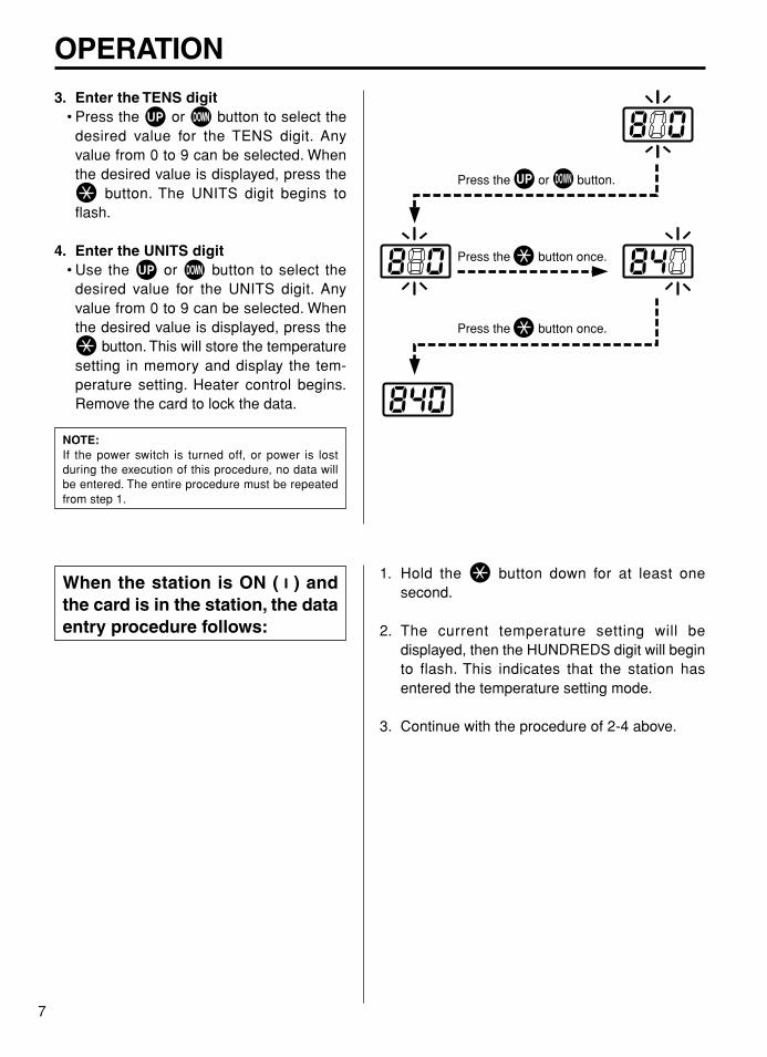
3. Enter the TENS digit• Press the or button to select the
desired value for the TENS digit. Anyvalue from 0 to 9 can be selected. Whenthe desired value is displayed, press the
button. The UNITS digit begins toflash.
4. Enter the UNITS digit• Use the or button to select the
desired value for the UNITS digit. Anyvalue from 0 to 9 can be selected. Whenthe desired value is displayed, press the
button. This will store the temperaturesetting in memory and display the tem-perature setting. Heater control begins.Remove the card to lock the data.
NOTE:If the power switch is turned off, or power is lostduring the execution of this procedure, no data willbe entered. The entire procedure must be repeatedfrom step 1.
When the station is ON ( ) andthe card is in the station, the dataentry procedure follows:
1. Hold the button down for at least onesecond.
2. The current temperature setting will bedisplayed, then the HUNDREDS digit will beginto flash. This indicates that the station hasentered the temperature setting mode.
3. Continue with the procedure of 2-4 above.
7

PARAMETER SETTING
The HAKKO 472D has the following parameters. Parameter settings can be adjusted.1. °C or °F temperature display selection.2. Low temperature tolerance.3. Display of room temperature compensation value (test mode)
Once parameter input mode has been entered, set the parameters in the order shown below. After allthe parameters have been set, normal operation will be resumed.
1. °C (Celsius) or°F (Fahrenheit)Temperature Display
1. Turn off the power switch.2. Insert the control card into the slot in the station.3. Press and hold the and buttons simultaneously, then
turn on the power switch.4. Continue holding down the and buttons until the
display shows °C (for Celsius) or °F (for Fahrenheit).5. When the display shows °C or °F, the station is in parameter
input mode.6. Pressing the or button will cause °C or °F to be
displayed alternately.7. Press the button to select the scale. The low temperature
tolerance may now be entered.
2. Low temperaturetolerance(Flashing of thetemperature display)
When the station enters the Low temperature tolerance settingmode, the HUNDREDS digit will begin flashing. Enter and storethe value in the same manner as described in ‘Changing thetemperature setting’.
Range of allowable heater error temperaturesFor °C: 30 – 150°C For °F: 60 – 300°F
If a temperature value outside this range is selected, the displaywill again flash the HUNDREDS digit. If this happens, reenter acorrect temperature value.After setting the low temperature tolerance value, the display willshow the room temperature compensation value (test mode).
3. Room TemperatureCompensation Value.(Test Mode)
The display will not blink and the heater will not receive power.The room temperature compensation value is the measuredtemperature of the nozzle. This function will be used later tocalibrate the nozzle temperature. (See “Recalibrate the Temper-ature” on P.13)
No inputs are made here. Press to complete parameterinput. The nozzle temperature setting will be displayed for 2seconds, after which power will be supplied to the heater andnormal temperature control will begin.
8

MAINTENANCE
Efficient desoldering depends upon the temperature, the quality and quantity ofthe solder and flux. Perform the following service procedures as dictated by theconditions of the iron usage.During maintenance, please wear gloves and work carefully.
WARNING:Since the desoldering iron can reach a very high temperature, please work carefully. Except whencleaning the nozzle and heating element, always turn the power switch off and disconnect the power plugbefore performing any maintenance procedure.
Servicing the Desoldering Iron
1. Inspect and clean the nozzle.• Plug in the power cord, turn the power
switch “ON” and let the nozzle heat up.• Clean out the hole of the nozzle with the
nozzle cleaning pin.If the nozzle cleaning pin does not passthrough the nozzle, use the cleaning drill(option).
NOTE:• The cleaning drill is not included.• The cleaning pin will not pass through the nozzle
until the solder inside the nozzle is completelymelted.
• Check the condition of the solder plating,surface and inside hole of the nozzle.If it is slightly worn, recoat the tip withfresh solder.
• If it is worn or eroded, or the insidediameter seems unusually wide, replacethe nozzle.
NOTE:The inside hole and the surface of the nozzle isplated with a special alloy.Should this alloy become eroded by hightemperature solder, the nozzle will not be able tomaintain the proper temperature.
• If the cleaning pin and cleaning drill do notpass through the hole in the nozzle,replace the nozzle.
The cleaning pin passes completely through the hole.
Cleaning with the nozzle cleaning pin.
Cleaning with the cleaning drill (option).
• Before cleaning
• After cleaning
Insert the bit while turning it clockwise.
Pull the drill bit out straight without turning it.
solder plating
Diameter of hole iswidened through erosion.
CAUTIONIf the cleaning drill is forced into the nozzle, the drill bit could break or be damaged.
CAUTIONPlease use the proper sized cleaning pin or cleaning drill for the nozzle diameter.
NOTE:Unfortunately, it is often diffi-cult to observe this condition, therefore, if desoldering effi-ciency goes down and all other parts appear to be OK, the nozzle is probably eroded and should be replaced.
9

2. Disassemble the heatingelement part.
CAUTION:The heating element is very hot during operation.
3. Clean out the hole in theheating element.Be sure the solder in the hole in theheating element is completely melted,then clean the hole with the cleaning pinprovided.If the cleaning pin cannot pass throughthe hole, replace the heating element.
Cleaning the inside of the filter case
1. Replace the ceramic paperfilter (S).Remove the ceramic paper filter (S) andinspect it. If it is stiff with flux, replace it.
2. Reassemble the filter case.
CAUTION:Insert the small ceramic paper filter into the filterretainer at the station. Using the large ceramic paperfilter may damage the unit, or reduce theeffectiveness of the unit.
Heating element
Remove the nut withthe spanner.
Nozzle
Element cover
Nut
Scrape away all oxidation from the hole in the heating element until the cleaning pin passes cleanly through the hole.
The cleaning pin passes cleanly through the hole.
Filter retainer
Ceramic paperfilter (S)
Remove the filter retainer and push out the ceramic paper filter.
VACUUM
Secure the vacuumoutlet cap.
Ceramic paperfilter (S)
Apply silicone grease to the O-ring (S-20) and securely tighten the vacuum outlet cap to prevent air leakage.
10

MAINTENANCE
Cleaning the pump
1. Disassemble the pump heads.• Unplug the power cord.• Remove the cover screws. (right/left)• Remove the cover.• Remove the pump head from each side of
the pump.
2. Clean the pump head.• Remove the valve plate and fixing plate.• Remove any flux adhering to the plates.• If the valve plate is bent or stiff, replace it.• If the exhaust filter is dirty, replace it.
CAUTION:• If the fixing plate is difficult to remove, apply hot air
to it to warm it up.• Never use excessive force to remove the plate as it
is easy to bend, and a bent plate will allow a leak,which reduces the efficiency of solder extraction.
• Clean the plates only with alcohol or thinner.
3. Assemble the pump heads.Reassemble the valve plate and fixingplate.
CAUTION:When assembling the pump, be sure to check for airleaks.
Clean the pump head and fixing plate.
Exhaust filter
Pump head
Pump head
Fixing plate
Fixing plate
Valve plate
Valve plate
Be sure the parts are aligned correctly.
11

REPLACEMENT PARTS
Filter holder Spring filter
Ceramic paper filter(L)
Back holder Filter pipe
Spring Ffilter
Filter holder
Front holder
1
234
Pins
Fastener
24V60W
24V60W
Fig. 3
Fig. 2
Fig. 1
Nut Nozzle
9Front holder
2
35
1
4
6 7
Back holder knob
Fig. 4
9
CAUTIONSecurely insert the spring filter to the end of the filter holder.
Element cover
Replacing the filters.1. Turn the back holder knob counterclock-
wise and pull out the filter pipe.2. If there is solder in two-thirds of the spring
filter, replace the filter.3. If the ceramic paper filter is stiff with flux
and solder, replace the filter.4. Insert the spring filter into the filter pipe.5. Insert the ceramic paper filter and put the
back holder into the filter pipe.6. Insert the filter pipe into the main body
and secure it by turning the back holderknob clockwise.
Replacing theheating element
Check the resistance valueThe resistance values of a working heatingelement are9.2Ω between pins 1 and 3 (heating element),54Ω between pins 2 and 4 (sensor) at 73°F (23°C)If the measured values are outside thisrange, replace the heating element.(No. A1174 24V-60W heating element forHakko 807)
Replacing the heating element 1. Unplug the cord. 2. Remove the nut, element cover, and
nozzle. 3. Turn the back holder knob counterclock-
wise and pull out the filter pipe. 4. Remove the housing fastener. 5. Remove the screws securing the housing
9 and the screws 3 4 securing theflange to the housing.
6. Remove the front holder. 7. Remove the screw 5 6 7 securing the
heating element to the flange, and thescrew 1 2 .
12

REPLACEMENT PARTS
8. Desolder the heating element leads(marked H) and sensor leads (marked S).
9. Remove the old heating element andreplace it with a new one.
10. Bend the lead wire as shown in Fig. 6,and pass two red leads and two whiteleads through the holes as shown in Fig.7. Secure a heating element to the flangewith the screws 5 6 7 .
11. Install the front holder.12. Resolder the heating element leads (red
wires/H) sensor leads (white wires/S).13. Reassemble the unit.
Recalibrate the temperature(a) Set the desire temperature.(b) Adjust the temperature calibration pot
(CAL) until the nozzle temperature(measured with a tip thermometer) iscorrect.
Pass the leads through the holes as shown.
Flange
Wires
HHS
S
Fig. 5
Fig. 6
Fig. 7Two red leads
Twowhite leads
CAUTIONBe careful not to twist and pull the lead wire when installing the heating element.
NOTE:Be sure the insulation on the leads touches the board. Do not leave any bare wire exposed.
13

ERROR MESSAGES
Various error messages will be displayed when there is a problem with the Hakko 472Dunit. If the following message is displayed, refer to “Trouble Shooting Guide”.
System Error After the power has been turned on, the systemchecks the memory and the programs. If anabnormality is found, will be displayed, andall operations will be completely stopped.
Sensor Error If there is a possibility of a failure in the sensor oranywhere in the sensor circuit, will bedisplayed and power to the desoldering iron will becut off.The sensor error also occurs if the cord assemblyis not properly connected.
Low temperature tolerance(Flashing of the temperature display)
If power is present at the desoldering iron and thenozzle temperature goes below the heater errortemperature tolerance setting, the temperaturedisplay will flash. This indicates the possibility of aheater malfunction.
EXAMPLE:Assume the temperature setting is 400°C (750°F)and the low temperature tolerance is 50°C(100°F). If, even though the heater is receivingpower, the temperature of the desoldering irongoes below 350°C (650°F) the display will begin toflash indicating a possible heater malfunction.
EXAMPLE:400°C – 50°C = 350°C (750°F – 100°F = 650°F)→ The display will begin to flash.
NOTE:If the temperature begins to rise again, the display will stopflashing – even if the displayed temperature is below 350°C(650°F).
BEFORE SERVICING ......WARNING:
• Disconnect the power plug before servicing.Failure to do so may result in electric shock.
• If the power cord is damaged, it must be replaced by the manufacturer, its authorisedservice agent, or a similarly qualified technician to avoid hazard.
14

REPLACEMENT/OPTIONAL PARTS
Replacement and optionalparts for Hakko 807
Spanner, cleaning brush,silicone grease, iron holder
• NozzlePart No. Part name/Description A1002 Nozzle S ø0.8 mm (0.03 in.) / Small A1003 Nozzle S ø1.0 mm (0.04 in.) / Small A1004 Nozzle ø0.8 mm (0.03 in.) A1005 Nozzle ø1.0 mm (0.04 in.) A1006 Nozzle ø1.3 mm (0.05 in.) A1007 Nozzle ø1.6 mm (0.06 in.)
Part No. øA øBA1487 0.6 mm (0.023 in.) 1.5 mm (0.059 in.)
A1393 1.0 mm (0.04 in.) 1.4 mm (0.055 in.)
A1002 0.8 mm (0.03 in.) 1.8 mm (0.07 in.)A1003 1.0 mm (0.04 in.) 2.0 mm (0.08 in.)
A1395 1.3 mm (0.05 in.) 2.1 mm (0.083 in.)
Part No. øA øBA1004 0.8 mm (0.03 in.) 2.3 mm (0.09 in.)A1005 1.0 mm (0.04 in.) 2.5 mm (0.1 in.)A1006 1.3 mm (0.05 in.) 3.0 mm (0.12 in.)A1007 1.6 mm (0.06 in.) 3.0 mm (0.12 in.)A1396 2.3 mm (0.09 in.) 3.8 mm (0.15 in.)
Part No. øA øBA1394 1.0 mm (0.04 in.) 2.1 mm (0.083 in.)
• Cleaning Pin/DrillPart No. Part name/Description B1215 Cleaning pin for heating element B1086 Cleaning pin for ø0.8 mm (0.03 in.) nozzle B1087 Cleaning pin for ø1.0 mm (0.04 in.) nozzle B1088 Cleaning pin for ø1.3 mm (0.05 in.) nozzle B1089 Cleaning pin for ø1.6 mm (0.06 in.) nozzle B1302 Cleaning drill for ø0.8 mm (0.03 in.) nozzle B1303 Cleaning drill for ø1.0 mm (0.04 in.) nozzle B1304 Cleaning drill for ø1.3 mm (0.05 in.) nozzle B1305 Cleaning drill for ø1.6 mm (0.06 in.) nozzle
Part No. Part name/Description B2100 Spanner (for desoldering iron) B1670 Cleaning brush A1028 Silicone grease
øA
øB
øA
øB
11 mm (0.43 in.)
øA
øB
C1316 Iron holder for Hakko 807
15

PARTS LIST (Iron)
NOTE:Spare or repair parts do not include mountingscrews, if they are not listed on the description.Screws must be ordered separately.
1
2
4
3
5
6
7
1814
11 8
9
17
13
12
16
10
Pan head screwM2.6 × 7 (7)Sus
Pan head screwM2.6 × 7 (1)Sus
Item No. 1 Nozzle See P.15
24V-60W 2 B1653 Element cover 3 A1174 Heating element 4 B1015 Nut 5 B1654 Flange 6 A1304 Front holder
Set of 10 7 A1030 Spring filter 8 B1655 Button
With switch 9 B1656 Board 10 B1916 Filter pipe
Set of 10 11 A1033 Ceramic paper filter (L) 12 B1657 Cord assembly 13 B1917 Back holder assembly
With a screw & fastener 14 B1659 Housing 15 B1023 Hose
Set of 4 16 B1024 Cord holder 17 B1660 Housing fastener
With filter holder & filters 19 B2517 Filter pipe asse’y 18 B1915 Filter holder
Part No. Part Name Description
15
19
16

PARTS LIST (Station)
Pan head screwwith washerM4 × 8 (4)
Pan head screwwith washerM4 × 6
Hexagon nutM4 (4)
Pan head screwM4 × 25
Pan head screwwith washerM4 × 6
Pan head screwwith washerM3 × 6 (8)
SpacerNominal size
4 × 25
Pan head screwwith washerM4 × 30
Spring washerNominal size 4 (4)
External toothlock washer
Nominal size 4
External toothlock washerNominal size 4
Pan head screwwith washerM4 × 12 (8)
Pan head screwwith washerM3 × 6 (4)
Pan head screwwith washer
M3 × 6
Flat head screwM4 × 8 (4)
Flat headscrewM4 × 12 (2)
Truss screwM4 × 5 (4)
External toothlock washer
Nominal size 4
472D StationItemNo.1234567891011121314151617181920
21222324252627282930313233343536
Part No.
B1029A1009B1063B1034B1031B1064B1662B1084B1204B2724B2314B2726B2727B2047B2388B2444B2728B1041B1275B2068
B2725B2729B1053B1312B2506B1057B2060B2059B2058A1013B2085B1056A1014B1050B1059B1313
Part Name
Vacuum outlet capCeramic paper filter (S)Filter retainerO-ringVacuum outlet retainerFilter case jointReceptaclePower switchRubber footChassisHose assemblyP.W.B. for displayP.W.B. for heat controlMembrane sheetControl cardPump assemblyTransformerFuse holderFusePower cord, 3 core &American plugCoverIron holderBalance weightCrankDamperRing for bearingCrank shaftPump flameMotorDiagramDiagram setting plateFixing plateValve platePump headExhaust filterFilter retaining pin
Description
Set of 10
S-20With O-ring & screws
With rubber foot
250V-2A (U)
Set of 2
With screw
Set of 2, with screws
Set of 2With screwsSet of 2
Truss screwNiM4 × 5 (8)
21
19
18
20
29
28
2726
24
23
25
3031
3233
3435
36
22
17
16
12
15
1
2
3
7
8
45
69 14
11
10
13
NOTE:Spare or repair parts do not include mountingscrews, if they are not listed on the description.Screws must be ordered separately .
17 18

WIRING DIAGRAM
Motor
Switch
Power cord
Fuse holder
Transfomer
P.W.B. for control
Iron
P.W.B. for display
CN3
CN
2
CN1
CN1CN2
1
2
1
2
1 4
1 3
1 3
1 4
1 5
2
34
HEAD OFFICE4-5, SHIOKUSA 2-CHOME, NANIWA-KU, OSAKA, 556-0024 JAPANTEL:+81-6-6561-3225 FAX:+81-6-6561-8466http://www.hakko.com/
AMERICAN HAKKO PRODUCTS, INC.28920 N. AVENUE WILLIAMS VALENCIA CA 91355, U.S.A.TEL: (661) 294-0090 FAX: (661) 294-0096Toll Free (800)88-HAKKO www.hakkousa.com 4 2 5 5 6
19 Nov. 2001MA01080JU011107