destruction and decontamination … convention/docs/meetings/sbc/workdoc... · training manual not...
TRANSCRIPT

DESTRUCTION AND DECONTAMINATIONTECHNOLOGIES FRO PCBs AND OTHER POPs WASTES
UNDER THE BASEL CONVENTION
A Training Manual for Hazardous Waste Project Managers
Volume A
Secretariat of the Basel Convention

Destruction and Decontamination Technologies for PCBs and
Other POPs Wastes
A Training Manual for Hazardous Waste Project Managers
Volume A
Part I. Basic Principles and Background Part II. Project Strategies Part III. Technology Selection Process

DESTRUCTION AND DECONTAMINATION TECHNOLOGIES FOR PCBs AND OTHER POPs WASTES UNDER THE BASEL CONVENTION – VOLUME A Published in October 2002 ISBN : ISSN : 1020-8364 Printed in chlorine-free cyclus paper This Publication may be reproduced in whole or in part and in any form for educational or non-profit purposes without special permission from the copyright-holder, provided that acknowledgement of the source is made. UNEP and the Secretariat of the Basel Convention would appreciate receiving a copy of any material that uses this publication as a source. No use of this publication may be made for resale or for any other commercial purpose whatsoever without prior permission in writing from UNEP.
This Publication is available from:
Secretariat of the Basel Convention International Environment House
15 chemin des Anémones, CH-1219 Châtelaine, Switzerland
Tel. : (4122) 9178218 Fax : (4122) 797 34 54
E-mail : [email protected]
Web : www.basel.int

CONTENTS
Part I – Basic Principles and Background…………………………………………….4
Part II – Project Strategies……………………………………………………………..12
Part III – Technology Selection Process……………………………………………….49
i

Foreword
This Training Manual has been prepared by the University of
Auckland, New Zealand in the context of the convening of the
First Continental Conference for Africa on the Environmentally
Sound Management of Unwanted Stocks of Hazardous Wastes
and their Prevention, Rabat, Morocco, 8-12 January 2001.
It has been designed to assist those governments or
organisations, not only in Africa, charged with the task of
managing the destruction or decontamination of POPs (Persistent
Organic Pollutants) with procedures that assist with the planning
and selection of appropriate technologies that suit the particular
circumstances whilst complying with the need for environmentally
sound management principles and the principles of sustainability.
In that context special consideration should be given to the local
national frameworks and the responsibilities of the relevant
competent authority.
New ideas and technologies are emerging rapidly and good
practices are still evolving. The Training Manual however will
remain useful in providing a selection process allowing new
technologies to be evaluated under the provisions of the Training
Manual and enabling organisations to continue to adopt new
technologies as they become available. There are four parts to
this Training Manual. Part Four is a detailed Field Application
Training Manual to the handling and environmentally sound
management of POPs as wastes covering obsolete pesticides
and PCB's in particular.
The Training Manual should be considered in conjunction with
other technical guidelines adopted by the Conference of the
Parties to the basel Convention and governing the
environmentally sound management of hazardous wastes, in
particular the Technical Guidelines on Wastes.
Comprising or Containing PCB's, PCTs, and PBB's (Y10),
Technical Guidelines for Incineration on Land,(D10), Technical
Guidelines for Specially Engineered Landfill (D5), and Technical
Guidelines on Wastes collected from Households (Y46). The
document should be considered in conjunction with other important
guidelines such as the FAO Pesticide series.
The writer refers in particular to the Draft Technical Guidelines
on the environmentally sound management of POPs wastes
which, at the time of printing of this document, are being
negotiated under the Basel Convention. Furthermore, this
Training Manual aimed at providing practical training for waste
managers should not be interpreted as preempting any of the
principles, guidance and recommendations that will form part
of the Technical Guidelines on the ESM of POPs wastes
mentioned hereabove.
Ron McDowall
International Centre for Sustainability Engineering and Research
Faculty of Engineering
University of Auckland
New Zealand
Secretariat of the Basel Convention (SBC)
International Environment House
11-13 chemin des anemones
Building D
1219 Chatelaine (Geneva)
Switzerland
Tel.: (+41 22) 917 8281
Fax.: (+41 22) 797 3454
E-mail: [email protected]

How to use this Training Manual
This Training Manual is designed as a desk top manual for planners, project
managers and government department staff. Its style aims to provide for ease of
reference and absorption of complex ideas and areas of uncertainty. The
Training Manual has been designed as a complete technical Training Manual for
the management of POPs as waste in an Environmentally Sound Manner. This
Training Manual not only covers the basic principles of hazardous waste such as
POPs but seeks to provide a step by step Training Manual as to how such
wastes are to be managed, packages, stored, transported, decontaminated and
disposed of. The step by step strategy culminates in a set of Work Procedure
Instructions that will allow a party to establish and manage a POPs waste project.
At the end of Part IV there is a sample set of Tender and Contract documents
that a party can use to create a contract for the management and handling of a
POPs project. This technical Training Manual is based on the integrated matrix
system of waste management and no part of the project can be initiated without
the preceding parts being carried out. The reader must understand that all parts
of this Training Manual have been consolidated to form a management
programme.
The Training Manual is designed to be used in several complementary ways:
• In creating a project strategy for disposal or decontamination
• In establishing the appropriate technology to be used
• In establishing a set of rules and methods to actually perform a
destruction of decontamination project.
• In providing the principles for site establishment and the basis for
an operational manual.
The Training Manual can help with
Planning
• understanding background and principles• correct inventory collation• inventory analysis
Writing project Plans
• produce an overall plan for disposal or decontamination
Technology Decision making
• appraisal of appropriate technology• selection of technology for destruction or
decontamination
Writing tender documents
• produce tender documents for destruction or decontamination
Hazardous waste project Implementation
• produce implementation plans
Project manual
• produce comprehensive destruction or decontamination manual

Structure of the Training Manual
I BASIC PRINCIPLES AND BACKGROUND
This section covers the background to the POP's problem and the
actions of international organisations to deal with the toxic waste
problems.
II POPs PROJECT STRATEGIES
The formulation of strategies for destruction and decontamination
depends on the inventory analysis. When the information Is
available then the strategy selection process commences.
III TECHNOLOGY SELECTION PROCESS
When the destruction and decontamination strategy is in place then
the specific technology decisions can be made and the appropriate
technology selected. several destruction and decontamination
technologies are presented in this section
IV IMPLEMENTATION PROCESS
Tendering and project management documentation and plans.
This section provides design guidance for site appraisals,
packaging of hazardous wastes, storage, transportation as well as
guidance for the destruction and decontamination processes.
Scope of the Training Manual
• The Training Manual can be used to prepare plans and
strategies for the project management of hazardous waste
projects involving intractable chemicals such as PCBs and
other POP's.
• The scope is such that any organisation can use it to
prepare simple plans for a small scale waste problem involving
less than 5 tonnes of material or for a large scale operation
involving say 5000 tonnes of material.
• In the final Part of the Training Manual there are planning
guides so that large projects that demand a high standard of
quality assurance are available.

PART I : BASIC PRINCIPLES AND BACKGROUND
Background
• Persistent Organic Pollutants (POPs) are chemical substances which are extremely stable,
and are known to accumulate in biological tissue thereby posing a risk of adverse effects to
human health and the environment. With the evidence of long-range transport of these
substances to regions where they have never been used or produced and the consequent
threats they pose to the global environment, the international community has on several
occasions called for urgent global actions to reduce and eliminate releases of these
chemicals.
• POPs, wastes fall under the scope of the Basel Convention which calls for the
environmentally sound management of hazardous wastes and the control of their
transboundary movements. The environmentally sound management conceptual
framework as agreed and defined by the 5th meeting of the parties (Basel Convention,
December 1999) is as follows; "Within the framework of integrated life-cycle management,
prevention to the extent possible and minimise the generation of hazardous wastes, treat
and dispose in such a way as they do not cause harm to health and the environment, and
eliminate or reduce transboundary movements of hazardous wastes".
• In its decision 19/13C of February 7, 1997 the Governing Council (GC) requested that the
Executive Director of the United Nations Programme (UNEP), together with relevant
international organisations, convene an intergovernmental negotiating committee (INC).
The INC was asked to prepare an internationally legally binding instrument for action on
twelve specified POPs. The GC also requested that UNEP develop and share information
on the following topics: alternatives to POPs, inventories of PCBs and available destruction
technology, and sources of and management strategies for PCDD/PCDF. The negotiations
under the INC led to the adoption of the Stockholm Convention in 2001.
Legislative Authority
• UNECE LRTAP POPs Protocol
(Long Range Transboundary Pollution)
• Olso-Paris Convention (NE Atlantic)
• Barcelona Resolution (Mediterranean)
• Arctic Environmental protection
• NAFTA/NACEC Resolution
• UNEP Global Programme of Action
• Stockholm Convention (2001)
4

• The twelve specified POPs covered by the Stockholm Convention are :
Pesticides: aldrinchlordane, dieldrin,DDT, endrin,heptachlor,hexachlorobenzene,
mirex,toxaphene.
Industrial Chemicals: PCB,
By-Products: Dioxins and Furans
Pesticides and PCB are covered by this Training Manual .
• This Training Manual will attempt to provide the practical application of these sentiments
while maintaining a realistic approach to destruction and decontamination. There are real
issues involved with the treatment, decontamination and disposal of hazardous wastes
particularly POPs and PCBs. This Training Manual will concentrate on POPs as waste and
in particular PCBs and unwanted pesticides and will provide practical guidance to solving
the issues of complexity that surround the Basel Convention statement on Environmentally
sound management of POPs and PCBs. In parts of this Training Manual POPs are treated
separately from PCBs as their situations and dispositions are different and require different
approaches.
Unwanted and Obsolete Pesticides
• Obsolete pesticides are stored and unused pesticides that can no longer be used for their
original intended use and there require disposal. There are many reasons for the existence
of stocks of unwanted pesticides. These can range from the pesticide being banned and
unsold stocks have remaining in storage, deterioration of the pesticides due to the length of
time in storage or improper storage, the products suitable is unsatisfactory and can no
longer be used for the original intended use, or other reasons such as chemical changes
that make the product unusable. It is difficult to ascertain whether or not the pesticides
product has become unusable. Generally it is not so difficult to ascertain if the product is
unwanted. It may be however that the product while unwanted in one situation is capable of
being used in another.
Key References
UNEP Basel Convention, 1989, Technical Guidelines for the Environmentally Sound management of PCB'sFAO Pesticide Disposal seriesUNEP Chemicals Toolkit for Dioxins and Furans, 2000UNEP Stockholm Convention, 2001UNEP Basel Convention, Technical Guidelines for theEnvironment Sound Management of POPs Wastes (draft)
5

• Unwanted pesticides are a major problem in many countries. For decades obsolete and
unwanted pesticide stockpiles have been building and accumulating in developing countries
so that now it is estimated that there are more then 200,000 tonnes of such material located
at thousands of sites all around the planet. Many of these chemicals (POPs) have long
been banned or are unusable for other reasons. Today there are often found in dangerous
storage conditions, leaking from rusted containers, contaminating ground water and soils
and poisoning the health and environment of people everywhere.
POPs (PCBs)
• Polychlorinated Biphenyls are a class of chlorinated hydrocarbons that have been used
extensively since 1930 for a variety of industrial uses. They consist of two benzene rings
joined by a carbon-carbon bond with chlorine atoms substituted on any or all of the
remaining carbon atoms. PCBs include mobile oily liquids and hard transparent resins,
depending on the degree of substitution. PCBs are generally found either as stored liquid
with contaminated equipment or still operating in the field. This Training Manual also
covers PCB in either case.
• The value of PCBs derive from their chemical inertness, resistance, non flammability, low
vapour pressure and high dielectric constant. As electricity came into widespread use
during the first half of the 20th century, equipment suppliers became major users of PCBs.
The major application involved PCB being used as a coolant and dielectric fluid in power
transformers and capacitors.
• The uses of PCBs can be classified as either closed or open. In closed applications it was
the intention to prevent any loss of PCB by containment within the sealed unit.
Declaration : New Zealand Government 1988
"Disposal of PCB wastes"
The Government's policy is that ALL PCBs shall be
withdrawn from service in five years time. All owners
of PCBs therefore need to prepare to replace existing
equipment and to remove it to storage and ultimate
disposal. Disposal of PCB oil and contaminated
equipment shall be by high temperature incineration or
by other approved method. Owners of PCB shall pay
for all costs involved with the disposal of PCBs.
6

Contamination of the environment was the consequence of equipment leak. In open
applications the PCB's were exposed to the environment, and some loss to the environment
was inevitable. The major closed applications were coolants in transformers and dielectrics
in capacitors.
• Between 1929 and 1989, total world production of PCBs was 1.5 million tonnes. After the
US banned the manufacture or sale of PCB except in Closed systems in 1976 production
continued at a rate of 16000 tonnes per year from 1980 to 1984 and some 10,000 tonnes
per year from 1984 to 1989.
• Many of the characteristics that make PCBs ideal for industrial applications create problems
when they are released into the environment. The effects on humans and the environment
primarily follow continual exposure. Like many other chlorinated hydrocarbons, PCBs
associate with the organic components of soils, sediments, and biological tissues, or with
dissolved organic carbon in aquatic systems. PCB's volatize from water surfaces in spite
of their low vapour pressure, partly because of their hydrophobicity. The chemical
properties of PCBs hampers their long range transport, and PCBs have been detected in
Arctic air, water and organisms.
• Despite the cessation of production in many countries from the mid 70s, PCBs continue to
be a pollutant of major concern on an international scale. There is still a substantial amount
of PCB still in use. This results from the long lifetimes of power equipment such as
transformers, and the exemption made in many countries for contained use for the lifetime.
There are relatively high quantities in storage awaiting disposal.
• Part of the world production has been destroyed, part remains in use or awaits destruction,
whilst a substantial proportion has been released into the environment. Depending on the
type and concentration levels there are several destruction and disposal options
available.
7

Sustainability
Sustainable engineering and technology focuses on pollution and the adaptation of cleaner
production. Pollution prevention minimises effluents and waste streams from products and
eliminates the need for treatment and control. Sustainable technologies are those that reduce
pollution through significant technical advances. For communities to be sustainable they must be
free from pollution in all its forms. This Training Manual attempts to integrate the elements of
recovery and management of PCBs and POPs and dispose of them in a manner that is Sustainable.
The Training Manual has detailed descriptions of example operating manuals for such activity and
has descriptions of various destruction and decontamination technologies, including high
temperature Incineration. It is the authors opinion that the plans and methodologies contained in
this Training Manual provide for sustainable destruction and decontamination technologies for
POPs and PCBs.
As the export of POPs as waste is not banned completely the concept of environmentally sound
management of POPs whatever the place of disposal is valid. The principle of environmentally
sound management of POPs provides that the wastes must be managed in such a way so as not to
endanger human health and then environment. Whereas it is embodied in most relevant
international legal instruments in a fairly vague and unspecified form it is given concrete content by
reference to standards established by non binding technical guidelines or codes of conduct in the
field. This document is written as a field application manual and provides a means by which
environmentally sound management of POPs as waste is delivered.
8

POPs Toxicity (Agrochemical)
Chemicals including pesticides are widely distributed in the environment. Therefore there are many possible sources of exposure to these chemicals for humans. Substances which are in ambient or indoor air may be inhaled while those in water or food may be ingested or inhaled. Direct contact with the chemical is the most prevalent way environmental chemicals can penetrate the skin, but exposure through the skin may also occur as a result of contact with chemical contaminants in air and water.
A single agrochemical can enter the body through all three routes of exposure, inhalation, ingestion and skin penetration (dermal exposure). A pesticide can involve more than one route of exposure if precautions are not taken. A pesticide can be inhaled during use or repacking, penetrate the skin during handling and be ingested through food if not washed off hands etc.
Once a agrochemical enters the body, it is often absorbed into the bloodstream and can move throughout the body. The amount absorbed and the rate of absorption depends on the chemical involved and the means of exposure. This movement of the agrochemical through the bloodstream is called distribution. Through distribution a chemical can come into contact with all parts of the body, not only the original site of entry. In some cases, contact located far from the point of entry can lead to adverse health effects. For example the ingestion of the pesticide parathion into the stomach can lead to substantial damage to the lungs.
Once a agrochemical is absorbed into the bloodstream, it can have several different fates. In many cases, it is rapidly removed from the body. In other situations it may be stored in various parts of the body, such as fat or bone and remain in the individual for many years. A compound may also lead to a toxic effect through interaction with certain organs or tissues in the individual or with other compounds in the body.
Often a agrochemical which is absorbed into the body interacts with particular body chemicals and is changed into one or more other chemicals. This process is called metabolism.
The particular properties of the absorbed chemical are quite critical to its fate in the body. Certain Agrochemical are very resistant to metabolism and readily dissolve into fat and are then stored. Dieldrin is a good example of this type of compound. Other chemicals are more rapidly metabolised and excreted before they can cause adverse effects. The organophosphate pesticides tend to behave this way at low doses. 9

In the case of a single event exposure it is the total amount of agrochemical to which are person is exposed that determines the severity of the toxic effect if any. The greater the amount of exposure the greater the potential for adverse health effects. In some cases this is due to the inherent toxicity of the agrochemical and in others to the inability for the body to defend itself. In the latter case the body may not be able to metabolise the chemical rapidly enough to prevent an increase in concentration to toxic levels. In such a situation there is a clear threshold above which toxic signs and symptoms appear.
In the case of repeated multiple exposures to an agrochemical it is not only the total amount of exposure but also the rate or timing of exposure that is quite important. All processes in the body normally proceed at specific rates so that metabolism excretion and storage occur during a particular period of time after a chemical is absorbed. For one occurrence exposure the time needed for the various processes that breakdown the compound to be completed will determine the length of time that a toxic response if any persists.
However if there are repeated exposures to the same chemical the situation is more complicated. If there is enough time between so that all of the chemical from the initial exposure is excreted and no effects persist then each exposure is essentially independent of the previous one and can be treated as a single exposure. However if the time between exposures is so short that some of the chemical remains from the first exposure then a build-up can occur. Over time this build up can lead to levels that are toxic.
The total amount of exposure can have different results depending on whether the exposure occurred all at once or repeatedly over time. A high dose given once may have the same toxic effect while the same total given in small doses over time will not.
The possible toxic effects of exposure to a particular agrochemical depends on many factors. These include characterisation of the chemical and the individual exposed, the route of exposure, the total dose and the time course exposure. Unfortunately scientists have not been able to determine exactly how each of these factors will affect any specific individual so that present understanding of agrochemical exposures only provides general guidance.
The procedures specified in this manual are designed to minimise exposure and this minimise the potential for adverse health effects.
10

POPs PCBs Toxicity
Polychlorinated Biphenyls (PCBs) are a mixture of chemicals and may be clear to yellow oily liquids or solids, vapour is invisible, and PCBs are heavier than water.
PCBs are a group of Chlorinated Hydrocarbons. Up to 209 different compounds exist in the PCB group. PCBs have the chemical composition C12 H10-nC1n. Specific chemical properties vary with the amount of chlorine.
PCBs are generally stable chemically and resistant to heat. They are fire-resistant, have a strong odour, are insoluble in water, and can be mixed with oils used in transformers and capacitors as insulating fluids ("Dielectrics"). Other uses included heat transfer fluids, hydraulic fluids, in brake linings, paints, sealants, varnishes, carbonless copy paper, cosmetics, etc.
PCBs do not break down readily. They persist in the environment and are absorbed by animals, and in fatty tissues. Once in the food chain they increase in concentration the further up the chain one goes ("Bioaccumulate").
As well as the risk from PCBs themselves, there is a risk from fires effect involving equipment containing PCBs. Such fires can produce toxic by-products including dioxin (Polychlorinated Dibenzoparadioxins, Poly Chlorinated Dibenzofurans and Hydrogen Chloride).
PCBs are thought to be hazardous to human health. The path of PCBs entering to the human body is by breathing, swallowing and passing through the skin.
No matter what, PCBs must be handled with extreme caution. Most commonly, inhalation of PCBs may lead to nausea and eye, nose and throat irritation. PCBs may also damage the liver.
High exposure to PCBs may damage the nervous system, causing numbness, weakness and tingling (pins and needles) in the arms and legs. Also high exposure to the skin may cause itching, sweating and burning sensations. Long-term high skin exposure may result in ridges in finger and toe-nails, acne and skin pigmentation.
High exposure through inhalation may irritate lungs and cause gastro-intestinal problems such as a reduced bowel capacity. Also the nervous system and skin problems mentioned above may be caused through inhalation in high exposure sites.
Research results do not confirm or conclusively show a causal relationship for the following effects :
1. PCBs may be teratogens (can cause fetal malformation in the first three months of pregnancy)
2. They may damage an adult's reproductive system.
The symptoms of high PCB levels in the body, as listed above, are often ( and possibly erroneously) directly related to the concentration of PCBs in the blood.
11

PART II PROJECT STRATEGIES
The process to developing an Environmentally Sound Management Project strategy for destruction
and decontamination is essentially the same for all POPs, PCBs and unwanted and obsolete
pesticides. There are seven steps involved and these steps are the same for all. The Training
Manual deals with each separately but follows the same seven steps.
Step one Declaration to dispose PCBs and POPs
The decision to dispose is where the whole process starts. When a country or organisation decides
that a POP or PCBs will be collected and disposed of and this is declared the entire process
commences at the point of declaration. The important key issues at the point of declaration are also
to state the boundaries of the disposal. Will it be only government agencies that have stock of PCBs
or POPs or will it also cover private or public companies. Will stocks without owners be included
and who will pay for the disposal. At the point of declaration the rules about end of service life for
equipment contaminated with PCBs will need to be stated. The declaration of disposal needs to be
short, clear and concise as to the boundaries of the project. Without a clear declaration it will be
difficult to determine which stocks are to be disposed of and which are not. Once the declaration
has been published then the project follows specific steps.
Step two Inventory data collection
POPs(PCBs)
The process involved with determining and selecting an appropriate destruction or decontamination
technique begins with the inventory stage. It is important to understand that the whole process of
selecting the destruction or decontamination stage is entirely dependent on the quality and quantity
of the information obtained during the inventory phase. It is not possible to correctly select an
appropriate technology unless the inventory stage is rigorous and detailed. The range of
concentration and disposition of PCB for instance is so vast that is is unacceptable to determine the
destruction or decontamination technology without the inventory analysis being in place.
Steps for the Environmentally Sound Management of
POPs as waste
STEP 1
Declaration
STEP 2
Inventory Data Collection
STEP 3
Inventory Data Analysis
STEP 4
Strategy Selection
STEP 5
Rationalisation
STEP 6
Technology Selection
STEP 7
Implementation

Step two - Inventory data Collection POPs(PCBs) continued
When the inventory analysis is complete and the stock’s size, concentration and disposition is
known then and only then can the process begin in order to establish the appropriate technology or
combination of technologies that will deal with the waste in a sustainable manner.
Depending on the inventory analysis there are many options available and this Training Manual will
provide a method for working out the best technology and management plan as well as provide
details of the available technologies.
The inventory data collection must be detailed enough to provide the following information. When
collecting data for PCB inventory there are four fundamental questions to be asked.
What is it?
Where is it?
How much is there?
Who owns it?
These questions are answered by the provision of the following data against the following segments:
In service transformers
Out of service transformers
Inservice capacitors
out of service capacitors
Bulk storage tanks, drums and containers
Compiling a National PCB inventory
Scope
• determine the regions to be inventoried
• locate areas where PCBs are likely to be found
• divide areas into logical units to be inventoried
Selection of facilities to inventory
• select those facilities that are lik;ley to have significant quantities of PCBs
• also consider facilities that may have disposed of PCBs inadequately
Facilities that may have PCBs
• electric utilities • research labs• industrial facilities • manufacturing plants• railroad systems • mining operations• military installations • landfills
Priority facilities
• electric utilities, power companies• electronics manufacturing• petrochemical plants• railroad systems• transformer repair • mining operations
13

Step two - Inventory Data Collection POPs(PCBs) Continued
For each of the segments there are several data required as follows.
In service transformers
KVA rating Brand nameFluid qty locationnumber (EPA) PCB concentrationYear of manufacture Scheduled year of replacementweight status/owner
Out of service transformers
KVA rating Brand nameFluid qty locationnumber (EPA) PCB ConcentrationYear of manufacture weightstatus/owner
In service capacitors
KVAr Rating Brand nameWeight number (EPA)location status/owner
Out of service capacitors
KVAr rating Brand by nameweight number (EPA)location status/owner
Bulk storage, drums, tanks etc.
Type locationweight fluid qtyPCB Concentration status/owner
The data entry for status can includes codes for leaking, stable, packed etc.
Which Inventory system to use
Self reporting or physical inventory
Considerations:-
• Scale of inventory• how many facilities• where are they located• complexity of facilities• responsiveness of industry
Self reporting management
• notifications• education• transmission of information• handling of responses• performing spot checks
Self reporting Notification/Education
•send forms and instructions to identified facilities
•use advertising•contact professional and trade associationsspecify places to call for assistance
Transmission of PCB survey information
•to whom should you send forms?• how long to wait for a response?•how should you follow up?
Handling of Responses
•check form for completeness•enter the information into the database• devise a process to ensure quality of data
14

Step two - Inventory data Collection POPs (PCBs) Continued
Selecting the equipment to be inventoried
• must do- transformers- capacitors
•ought to do
- hydraulic fluids- oil filled cables
•get information on
- PCB containing wastes- Soil contamination
Determining if the equipment contains PCB.
•look for manufacturers label•locate other records or information about the equipmentapply assumption rules
Assumption rules
Transformers and capacitors with no information Assume PCB
Transformers with mineral oil dielectric fluids Assume PCB contaminatedand no other information
Circuit breakers, voltage regulators, Fluorescent light ballasts Assume PCB contaminated.with no information
Inspect service records
•determine if the equipment has been retrofilled• if retrofilled obtain records ppm levels
Sampling and analysis
•direct sampling of dielectric fluids-from equipment drums etc.
Testing for PCBs
•simple screening tests (done on site using kits)
-density-chlorine content
Laboratory testing-gas chromatography
Communicating with facility management
•obtain co-operation of facility managers before conducting the inventory
•explain the purpose of the inventory• schedule the inventory visit•discuss equipment locations, if possible•learn plant safety procedures
Conducting the inventory
• facility entry•preinventory meeting with facility managers•selecting the equipment to be inventoried•working with facility managers to conduct the inventory•inventoring•sampling and analysis•completing the inventory form•post inventory meeting
15

Step two Inventory Data collection POPs and Unwanted and obsolete pesticides
In many respects the inventory data collection for POPs other than PCBs including unwanted and
obsolete pesticides is very similar to that of PCBs. The four questions are the same;
What is it?
Where is it?
How much is there?
Who owns it?
Whereas the testing and sampling of PCB is a relatively straight forward exercise, in the field for
pesticides and POPs as waste in general it is a different matter. In many cases of long term storage
of POPs and unwanted and obsolete pesticides the question "What is it?" becomes very difficult
However it is very important that during the inventory process the "what is it?" question is answered
fully. There are many experts available that can readily identify the class of pesticides and agri-
chemicals in general and at the very least the class must be identified. This is because unlike PCB
the segregation of the various unwanted agri-chemicals classes is very important when the material
is to be transported.
During the process of repackaging of POPs, waste streams must be kept separate and hence the
inventory data collection process must identify the streams. A waste steam can be made up of
separate types of waste so long as they are compatible with each other. The first step is to keep
liquids and solids separated from the very beginning. The inventory data collection must therefore
contain information that permits the construction of a segregation strategy which will eventually
impact on the transportation strategies.
Pesticides are categorised into groups of pesticides, such as organic chlorine pesticides, organic
phosphorus pesticides and pyrethroide pesticides. Pyrethroide pesticides have a low toxicity level,
chlorinated pesticides are toxic, but not acute, phosphorus pesticides are acute toxic.
Class segregation rules
(a)Formulations. All powder, liquid and aerosol
formulations of agri-chemicals shall be kept
segregated.
(b)Herbicides. All herbicides should be stored in a
segregated area of the store, and on their own, to
prevent cross contamination.
(c)Sodium Chlorate/Potassium Chlorate. These are
scheduled class oxidising agents and must be
segregated in storage so that they do not come
into contact and react with any combustible
materials, or acids.
(d)Pool chemicals. Calcium hypochlorite shall not
be stored with any agri-chemicals (or any other
chemical) as contamination can cause
spontaneous explosion.
(e)Soil Fumigants. Methyl bromide, chloropicrin,
dichloropropane,dichloropropene and other soil
fumigants shall be segregated in storage so that
they cannot come into contact with any other
chemical at any time.
(f) Lubricants, Brake fluids Under no circumstances
shall these be stored with any agri-chemicals.
(g) Potassium, calcium and ammonia nitrate
fertilisers. Under no circumstances shall these
fertilisers be stored with agri-chemicals.
16

Step two - Inventory Data Collection - POPs and Unwanted Pesticides (Cont)
Inventory data for unwanted and obsolete pesticides should include:
locationclasses and type of materialweight and volumes of each materialOwner informationstorage situationleakage and contamination informationproduct information - active ingredient, formulation, concentrationproduct age and condition
As for PCBs the inventory data collection for other POPs is the starting point for the formulation of a project plan to deal with the unwanted and obsolete pesticides. An additional factor for a pesticides project is site stabilisation. During the inventory data collection information is collected that provides details of the site situation and disposition of the chemicals o that during the project activity a stabilisation of the site can be applied. Within the project plans outlined in this Training Manual this is covered in the site clearance and site preparation plans.
FAO STANDARD INVENTORY FORMS FOR RECORDING OBSOLETE PESTICIDES
Product FormA product sheet needs to be completed for each product (if one product is kept in different types of containers, one sheet should be completed for each type of container)
SHEET NUMBER: ........................................... DATE: ...................................................OWNER OF PRODUCT: .................................... STORAGE SITE: .....................................LABELS ON CONTAINERS: TRADE NAME: ................................................. ACTIVE INGREDIENT(S): ..........................FORMULATION TYPE: ...................................... CONCENTRATION: ................ g/litre or g/kgMANUFACTURER: ........................................... BATCH NUMBER:......................................MANUFACTURE DATE: ..................................... ARRIVAL DATE: ......................................CONTAINER TYPE: ......................................... UNIT SIZE: .............................................NUMBER OF CONTAINERS: ............................. QUANTITY: .............................................ORIGIN: purchased by Government / received as donation (name donor): ................................
imported by private company (name company): ........................................................CONDITION OF PESTICIDE: usable / unknown / deterioratedCONDITION OF CONTAINERS: good/ minor damage / serious damage
transportable / not transportabledescription of damage: ..............
HAVE CONTAINERS BEEN OPENED? yes / some / no / not certainREASON FOR NOT USING THE PRODUCT:expired / deteriorated / banned / wrong formulationno need / stock too large / no longer recommendedOther: ........................................................REMARKS: .................................................................................................................
Pesticides Management Flow chart
Inventory data collection and evaluation
Site Stabilisation and Temporary Storage
Disposal
Prevention of accumulation
17

Step three Inventory Analysis POPs (PCBs)
The information contained in the inventory analysis allows us to commence the planning required to
derive a destruction and decontamination strategy. There are several steps to this phase.
Inventory Analysis Step 2 - Data Breakdown
With the data collected during the inventory phase a breakdown of the information is required. This
breakdown is designed to discover the size and nature of the waste material so that groupings can
be assigned so that the appropriate technology selection process can be applied. Ultimately there
are two overall categories. The first is material that is to be decontaminated and the second is
material for destruction. It is very important to get the waste PCB properly assigned so that the
appropriate technology can be selected. While the inventory data may refer to simply PCB
transformer it is necessary to know the amounts and the concentrations of PCB as this will have a
material effect on the technology selected to either decontaminate the transformer or to export it for
destruction.
Inventory Analysis Step 3 - Establish groupings
For PCB contaminated equipment it is necessary to establish groupings for the waste to be
categorized into. The groupings below are a suggestion for likely groupings that are based on
appropriate technology for the decontamination of destruction of the PCB. The groupings should be
laid out on a matrix so that amounts can be entered into and then the summarising can be done.
Likely PCB groupings
Gp 1 In service transformers (all sizes) with less than 50ppm PCB
Gp 2 In service transformers (less than 500KVA) with 50-5,000 ppm
Gp 3 In service transformers (less than 500KVA) with 5,000-50,000 ppm
Gp 4 In service transformers (More than 500KVA) with 50-5,000 ppm
Gp 5 In service transformers (more than 500KVA) with 5,000-50,000ppm
Gp 6 In service transformers (more than 500KVA with 50,000-900,000ppm
Inventory Analysis process for POPs (PCBs)
STEP 1
Inventory Analysis
STEP 2
Data Breakdown
STEP 3
Establish Groupings
STEP 4
Estimate Quantities
STEP 5Summarise Data into
Groups
STEP 6Summarise Data for
decontamination
STEP 7Summarise Data for
Destruction
18

Step three Inventory Analysis (Cont)POPs (PCBs)
Gp 7 Out of Service transformers (all sizes) with less than 50ppm
Gp 8 Out of service transformers (less than 500KVA) with 50-5,000ppm
Gp 9 Out of service transformers (less than 500KVA) with 5,000-50,000ppm
Gp 10 Out of service transformers (less than 500KVA) with 50,000-900,000ppm
Gp 11 Out of service transformers (more than 500KVA) with less than 50ppm
Gp 12 Out of service transformers (more than 500KVA) with 50-5,000ppm
Gp 13 Out of service transformers (more than 500KVA) with 5,000-50,000ppm
Gp 14 Out of service transformers (more than 500KVA) with 50,000-900,000ppm
GP 15 Empty out of service transformers
Gp 16 In service Capacitors
Gp 17 Out of Service capacitors
Gp 18 Storage tanks with oil less than 50ppm
Gp 19 Storage tanks with oil greater than 50ppm
This grouping breakdown is placed on a matrix with the quantities from the inventory analysis and
then the matrix is passed to the next step in the process which is the strategy selection.
PCB Inventory Analysis - Step 2 Data Breakdown
PCB Manu Type Service Owner KVA/r Total Oil Wt Oil Qty PCB GpType No. No. Weight Kg Kg Litres ppmT/F ABB TM 134 TPC 250 450 185 250 <50 1T/F Tyree OB 145 TPC 5000 12500 2500 4000 >50000 6Caps T&J TYY 1485 PDC 125 60 25 35 5000 16
Photo : Type 7 storage
Step 2 Data Breakdown involves the organising of the
inventory data types and quantities into the grouping.
19
Step three Inventory Analysis (Cont)
POPs (PCBs)
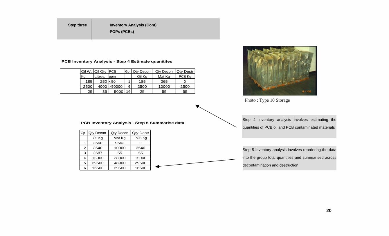
PCB Inventory Analysis - Step 4 Estimate quanitites
Oil Wt Oil Qty PCB Gp Qty Decon Qty Decon Qty DestrKg Litres ppm Oil Kg Mat Kg PCB Kg
185 250 <50 1 185 265 02500 4000 >50000 6 2500 10000 2500
25 35 5000 16 25 55 55
PCB Inventory Analysis - Step 5 Summarise data
Gp Qty Decon Qty Decon Qty DestrOil Kg Mat Kg PCB Kg
1 2560 9562 02 3540 10000 35403 2687 55 554 15000 28000 150005 29500 48900 295006 16500 29500 16500
Photo : Type 10 Storage
Step 4 Inventory analysis involves estimating the
quantities of PCB oil and PCB contaminated materials
Step 5 Inventory analysis involves reordering the data
into the group total quantities and summarised across
decontamination and destruction.
20

Step three Inventory Analysis (Cont)
POPs (PCBs)
PCB Inventory Analysis - Step 6 Decontamination
Gp Qty Decon Qty Decon TotalOil Kg Mat Kg Decxon Kg
1 2560 9562 121222 0 10000 100003 2687 55 27424 0 28000 280005 0 48900 489006 0 29500 29500
TOTAL 131,264
PCB Inventory Analysis - Step 7 Destruction
Gp Qty Decon Qty Dest TotalOil Kg Mat Kg Destr Kg
1 0 0 02 3540 0 35403 0 0 04 15000 0 150005 29500 0 295006 16500 0 16500
TOTAL 64,540
Photo : Type 6 Storage
Step 6 Inventory analysis involves summarizing the
total amount to be decontaminated
Step 7 Inventory Analysis involves summarising the
amount to be destroyed
21

Step 3 Inventory Analysis
POPs (Unwanted and Obsolete pesticides)
The analysis for unwanted pesticides and POPs is somewhat simpler than for PCBs. Generally the
waste falls into the broad classes of segregation and in the main these products must be exported
for destruction rather than local decontamination. Decontamination procedures may be required for
soil and water clean up and this in the main involves extraction of the contaminated soil rather than
treatment of it. There are some technologies however that can be used in situ for soil contaminated
with pesticides and involve bioremediation or phytoremediation.
The analysis must provide detailed summaries of the quantities of stored waste and the location and
disposition of it. Whereas the inventory analysis for PCBs generally falls into two categories,
decontamination or destruction, the analysis of inventory for pesticides should be broadly placed into
the four categories as follows;
Obsolete products requiring disposal
Products requiring further identification and testing
Usable products
Usable after reformulation
Obsolete products requiring disposal
• products that are banned
• Products that are deteriorated beyond usability
• Products that testing has show to beyond
usability
• Contaminated products rendering them
unusable
Products requiring further identification
• Unidentified products
• Older products passed use by dates
Usable products
• Use is still permitted and not unusable
Usable after reformulation
• Products in good condition but need
reformulating so they can be reused.
22

Step 4 Strategy Selection
POPs (PCBs)
The quality of the inventory analysis becomes important at this stage. So that the correct technology
is selected that data contained in the matrix from stages 1,2 and 3 must be accurate.
The actual grouping make up will also have a bearing on the combination of technology selection. If
there is much more of one grouping over another then a single technology may be chosen to cover
all the stock.
The possible technology selections for PCBs that can be made against each of the groupings above
are as follows:
Gp1 In service transformers (all sizes) with less than 50ppm PCB
In general in service transformers with less than 50ppm may be left in service and not touched. Retrofilling is possible but this creates stocks of lightly contaminated oil. In the main most countries prefer to treat below 50ppm as not PCB. From an environmentally sound management point of view with retrofilling producing stocks of contaminated oil the best option is to leave the less than 50ppm as it is.
Gp2 In service transformers (less than 500KVA) with 50-5,000 ppm
For transformers in service with less than 5000ppm retrofilling is cost effective and valid with in situ treatment not cost effective for transformers of this size.
Gp 3 In service transformers (less than 500KVA) with 5,000-50,000 ppm
Retrofilling with in situ treatment of solvent washing or bio reaction and circulating polishing with Perchloroethylene. Also replacement option is valid
Gp 4 In service transformers (More than 500KVA) with 50-5,000 ppm
Retrofilling with in situ treatment is required due to the size of the transformers and the capacity for long term leaching. Removed oil which may be up two two times the transformer capacity will require to be destroyed. Replacement option not valid due to high capital cost and destruction costs.
<50ppm
More than 50ppm but less than 5000ppm
Retrofill & Solvent wash
Yes
More than 5000ppm but less than 50,000ppm
In service Transformer
Replace transformerOil for destructionTransformer for decontamination
Drained Oil
Local Autoclaving
Offshore Destruction for the oil only
Local recycling industry
No
Note : Only Oil, Internal Transformer cardboard, wood and ceramics etc is ever destroyed. All other transformer components, steel, copper, aluminium are recovered and recycled.
23

Step 4 - Strategy Selection - POPs - PCBs (Cont)
Gp 5 In service transformers (more than 500KVA) with 5,000-50,000ppm
Retrofilling with in situ treatment for residual leaching. Recovered contaminated oil must go for destruction.
Gp 6 In service transformers (more than 500KVA) with 50,000-900,000ppm
Oil for destruction and transformer for decontamination and recycling after autoclaving.
Gp 7 Out of Service transformers (all sizes) with less than 50ppm
Oil for destruction, transformer may be reused or recycled
Gp 8 Out of service transformers (less than 500KVA) with 50-5,000ppm
Oil for destruction, transformer for solvent washing and reused or recycled
Gp 9 Out of service transformers (less than 500KVA) with 5,000-50,000ppm
Drain Oil for destruction, transformer to autoclaving, solvent washing and recycling
Gp 10 Out of service transformers (less than 500KVA) with 50,000-900,000ppm
Drain Oil for destruction, transformer for autoclaving, solvent washing and recycling
Gp 11 Out of service transformers (more than 500KVA) with less than 50ppm
Drain oil for destruction, transformer for autoclaving, solvent washing and recycling
Gp 12 Out of service transformers (more than 500KVA) with 50-5,000ppm
Drain oil for destruction, transformer for autoclaving, solvent washing and recycling
Gp 13 Out of service transformers (more than 500KVA) with 5,000-50,000ppm
Drain oil for destruction, transformer to solvent washing, autoclaving and recycling
Photo:Type 1 Storage
24

Step 4 Strategy selection - POPs - PCBs (Cont)
Gp 14 Out of service transformers (more than 500KVA) with 50,000-900,000ppm
Drain oil for destruction, transformer for autoclaving and recycling
GP 15 Empty out of service transformers
Autoclaving and/or solvent washing and recycling
Gp 16 In service Capacitors
Remove and send for shredding and destruction or autoclaving
Gp 17 Out of Service capacitors
Shredding and autoclaving or destruction
Gp 18 Storage tanks with oil less than 50ppm
No action
Gp 19 Storage tanks with oil greater than 50ppm
Drain oil for destruction, solvent wash tank.
Photo : Temporary bunding for transformer decanting
25

Step 4 Strategy selectionPOPs Unwanted Pesticides
Compared to management of PCBs unwanted and obsolete pesticides have another step that must
be applied before the disposal strategy is selected. This involves site stabilisation. Generally is is
helpful if this process is done with the inventory and data collection phase but in reality it is done at a
later date. Stabilisation of sites in necessary to reduce further loss to the environment and
increasing risks to the local population and site workers. Site stabilisation involves repackaging of
the unwanted chemicals that are leaking from unstable and deteriorated containers. Site
stabilisation also involved segregation of classes and separation of dangerous combinations. It is
during this phase along with the information from the inventory analysis that the strategy selection
for destruction and decontamination can commence.
In the main for unwanted and obsolete pesticides and POPs in general decontamination is not an
option apart for contaminated soils. Destruction is required for those products that cannot be reused
as they are, or reused after reformulation. The disposal or destruction method chosen will depend
on the type and quality of product involved and local circumstances. While a destruction technology
may be suitable for one situation it may be unsuitable for another. This means that the process of
formulating a strategy will have to consider the combination of the technology and the chemicals
involved at the particular site.
The five main alternatives for strategy selection are :
high temperature incinerationlandfillchemical treatmentlong term storageball milling
These alternatives are discussed in PART III of the Training Manual.
26
Step 5 Rationalisation PCBs
Given the amount of PCB oil to be disposed of, should the country import the technology to
incinerate the oil using a mobile incinerator or due to the low quantities should it be exported to
another country that is set up with incineration facilities. Would it be feasible to import Plasma Arc
technology and dispose within the country. What are the issues of dioxins and furans that impinge
on this decision and are they managed by the chosen technology. Is storage long term a feasible
option so that when a cheaper more friendly option is available then disposal can occur. Should the
country import dechlorination, solvent washing, autoclaving technology or biotech technologies to
decontaminate the PCB equipment? Can the recycling business cope with the materials from the
autoclaving process. All of these decisions depend on the quantity of the material, the concentration
(PCBs) of the material, the infrastructure available within the country and the logistical framework
necessary to handle the project. The steps involved in the rationalisation activity are as follows:
• After the basic strategy selection has been performed the matrix is updated to show the
reality of the chosen strategies and thus the quantities of materials that will be available to
each part of the chosen strategies.
• It is then appropriate to rationalise the process by examining the matrix to see where the
bulk of the material lies and determine where a particular group may be combined with
another group as far as treatment is concerned.
• Major decisions are made at this point based on the reality of the country situation and the
disposition and size of the waste to be disposed. It is during this stage that the
requirements of environmentally sound management are delivered. Decisions in this step
include;
• export all or part of the PCBs
Extracts from the Basel Convention(d) Ensure that the Transboundary movement of
hazardous wastes and other wastes is reduced to a
minimum consistent with the environmentally sound
and efficient management of such wastes , and is
conducted in a manner that will protect human
health and the environment against the adverse
effects which may result from such movement:
(e) Not allow the the export of hazardous waste
or other wastes to a State or group of States
belonging to an economic and/or political integration
organisation that are Parties , particularly
developing countries, which have prohibited by their
legislation all imports, or if it has reason to believe
that the wastes in question will not be managed in
an environmentally sound manner, according to
criteria to be decided on by the Parties at their first
meeting.
(f) Require that information about proposed
Transboundary movement of hazardous wastes
and other wastes be provided to the States
concerned according to annex V.A to State clearly
the effects of the proposed movement on human
health and environment:
(g) Prevent the import of hazardous wastes and
other wastes if it has reason to believe that the
wastes in question will not be managed in an
environmentally sound manner:
27

Step 5 - Rationalisation - PCBs (Cont)
• Construct or import PCBs destruction or decontamination technology
• remove PCB contaminated equipment from service or leave in situ and treat
All of these questions and decisions must be framed within the concept of environmentally sound
management, minimisation of transboundary movements, sustainability and sound management
practice as well as economic considerations. A balance must be achieved here that provides a
solution that is best for all the elements described. It will not be possible to satisfy all of the
requirements. It may be that the best environmentally sound management solution involves total
export because the rationalisation analysis has indicated that it is not technically feasible nor
economically feasible to develop an indigenous technology or import a technology to dispose of
small amounts of highly contaminated PCB oil. On the other hand it may be feasible to import
autoclaving systems to take care of decontamination of empty transformers with the concentrated
PCB oil being exported for destruction. These are the decision that can only be made after the
rationalisation procedure is complete and that procedure is dependent on an accurate inventory
analysis.
Rationalisation decisions
Export all and replacement
Treat all material locally
Combination local and export treatment
In situ Treatment
Replacement and storage
Import technology
-Incineration-Autoclave-Bio-Vitrification-dechlorination-Plasma Arc
28

Step 5 Rationalisation
POPs - Unwanted or obsolete pesticides
In a similar manner to that of rationalisation for PCBs, POPs and unwanted or obsolete pesticides
must go through rationalisation. Because unwanted or obsolete pesticides are generally sent for
destruction the rationalisation involves the feasibility of the various options open to the country
involved. If high temperature incineration is chosen should it be a mobile machine imported to the
country or should the waste travel overseas to a developed country that provides a service of
destruction using a HTI. It is usually not an option for a developing country to consider constructing
its own high temperature incinerator as a fixed plant. The cost for this is prohibitive and there are
issues related to operational safety and training etc. It is feasible to import a mobile High
temperature incinerator that can be transported from site to site should there be sufficient material
available to make it economic. Quantities at each site would need to be in the order of 7000 tonnes
for this option to be successful.
Cement kilns can provide a useful alternative for purpose built HTI but it needs to be a rotary kiln
with appropriate gas treatment systems such as an electrostatic precipitator. Often the owner of the
cement kiln will not allow its use for pesticide destruction. The time taken to evaluate and determine
such kilns can be used usually exceeds that required for other options.
Export to a HTI incinerator in a developed country is a valid option for all quantities from one tonne
to 10,000 tonnes and more. These days the cost of HTI incineration for pesticides is very
competitive and is the preferred technology at this time.
In situ chemical treatment is an option but there are many problems associated with performing
treatment within developing countries. Generally it is often not cost effective when compared to
incineration and difficult to ensure environmental protection during treatment. Chemical treatment is
generally viewed as simply preparing the product for further treatment such as landfilling or
incineration rather than an end in itself.
Ball milling is an emerging technology that has huge
promise for on site treatment and destruction of
obsolete pesticides - details in Part III
29

Step 5 Rationalization Project Strategy Management
For hazardous waste projects of some size there needs to be a project
management strategy for the implementation of the strategies chosen. While PART
IV has a full set of implementation plans there needs to be an understanding of
basic project management and that is defined here, There are five distinct areas
that are required to be “managed” so that the waste project is successfully
completed. These five areas of the waste project areas that must be managed by
the project team and they are described as management functions.
Managing Scope
Managing Project Organisation
Managing Quality
Managing Cost
Managing Time
Each of these elements is delivered within the Implementation plans in PART IV.
Within each of these five elements is the element of risk management and this is
discussed separately.
Before these elements are considered the project definition must be formulated.
The project definition initiates the project and therefore relates the work to projects
objectives.
30
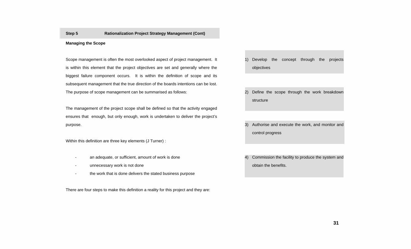
Step 5 Rationalization Project Strategy Management (Cont)
Managing the Scope
Scope management is often the most overlooked aspect of project management. It
is within this element that the project objectives are set and generally where the
biggest failure component occurs. It is within the definition of scope and its
subsequent management that the true direction of the boards intentions can be lost.
The purpose of scope management can be summarised as follows:
The management of the project scope shall be defined so that the activity engaged
ensures that enough, but only enough, work is undertaken to deliver the project’s
purpose.
Within this definition are three key elements (J Turner) :
- an adequate, or sufficient, amount of work is done
- unnecessary work is not done
- the work that is done delivers the stated business purpose
There are four steps to make this definition a reality for this project and they are:
1) Develop the concept through the projects
objectives
2) Define the scope through the work breakdown
structure
3) Authorise and execute the work, and monitor and
control progress
4) Commission the facility to produce the system and
obtain the benefits.
31

Step 5 Rationalization Project Strategy Management (Cont)
The main emphasis is at the start of this process, as the mistakes made here are rarely
corrected. Item 3 above is the purpose behind the “Ownership” of the project. The
development of the Project Concept (1) is a critical issue and this must be properly completed
after the project leader has had the opportunity to evaluate the site situation .
Work Breakdown structure (2) is a process by which during the first stage of formulating the
management of the project the work of the project is divided and subdivided for management
and control purposes. In preference to breaking the project into a low level of detailed in a
single step the idea is to devolve through increasing levels of detail. Therefore the work
breakdown structure is developed by breaking the project into intermediate and sub project
steps and the work required to execute that sub group is identified.
There are three fundamental levels of work
breakdown:
Integrated
Strategic
Detail
32

Step 5 Rationalization Project Strategy Management (Cont)
For this project due to its nature of involving the entire Business the Work breakdown must start at
the first Breakdown level and progress down. As it devolves downwards then the detail level breaks
down into project phase, task, activity etc and there will be probably about seven levels that are
finally listed. This process as mentioned devolves as the project unfolds and the detail of the
project becomes clearer as a result of the business purpose clarification.
The advantages of the Work Breakdown concept are:
- It provides better control of work definitions
- It allows work to be delegated in coherent packages
- It allows work to be defined at an appropriate level for estimating and control of the
current stage
- It allows risk to be contained within the work breakdown structure
The use of work breakdown structures will satisfy the principles of good management:
1 Manage through a structured breakdown of the project
2 Focus on results: what to achieve and how to achieve it
3 Balance results through the work breakdown, between areas of technology, people,
systems and organisation
4 Organise a contract between all the parties involved, by defining their role,
responsibilities and working relationships
5 Adopt a clear and simple reporting structure
In order to create the work breakdown the process of
defining the project must be carried out :
Defining Projects
The project definition always has the role of initiating
the project and therefore as previously mentioned
relates the work of the project to management's
requirements. The following three requirements
should be defined:
- the purpose
- the scope
- the objectives
33

Step 5 Rationalization Project Strategy Management (Cont)
The purpose statement should be clear and concise and once the project is underway it will become
the mission of all those involved in the project, both as team members and as resource providers.
The scope is an initial high level description of the way in which the purpose will be commissioned.
The Statement of Scope should include two elements:
- The work that falls within the remit of the project and is required to achieve the
benefits
- the work that falls outside of the remit of the project
The objectives should be quantitative and qualitative measures by which the completion of the
project will be judged. In effect they define the outcome that will be produced. The objectives
should address:
- address all the work within the scope of the project
- not address work outside of the scope of the project
- begin to set the parameters for managing quality, cost and time.
34

Step 5 Rationalization Project Strategy Management (Cont)
Summary of Managing Scope
The purpose of scope of management methodology is to ensure that :
- adequate work is done
- unnecessary work is not done
- the project’s purpose is achieved
There are four steps of scope management:
- develop the concept through the projects objectives
- define the scope through the work breakdown structure
- authorise and execute the work, and monitor and control progress
- commission the project and produce the benefit
Work breakdown is a process by which the work is subdivided for management,control
purposes and logical arrangement purposes.
The project is defined at the strategic level through;
- the purpose
- the Scope inclusions and exclusions
- the objectives
At the strategic level the Milestones
plan:
- shows how the deliverables build
towards the final objectives
- sets a stable framework
- controls the unfolding and devolution
of the management of the scope
A good milestone plan
- is clear, simple and concise
- focusses on necessary sections
- gives an overview of the project
There are seven steps in milestone planning
- agree the final milestone
- brainstorm milestones
- review the list
- experiment with result paths
- draw the logical dependencies
- make the final plan
Plans at the lower level include:
- subsidiary milestones plans
- work package scope statements
- activity plans developed on a rolling
wave basis.
35

Step 5 Rationalization Project Strategy Management (Cont)
Managing Project Organisation
The next major project management objective is that related to managing the project
Organisation. Through this process the project Manager defines the type and level of
resources inputs, and how they are to be managed in order to achieve the purpose of the
project that has been stated in the management of scope.
When the Scope and the Organisation have been fully defined they represent the Project
Contract that then exists between the project team and the Corporate Management.
The purposes, principles and processes of project organisation are defined as below;
Project Organisation Purpose is defined for this project as follows:
to assemble sufficient resources (human, material and financial) of the appropriate type and
quality to undertake the work of the project and to deliver the strategic intention of the project.
Three of the principles of good project management are discharged by the management of the
project organisation:
- negotiate a contract between all parties
- assign roles and responsibilities at all levels of work breakdown
- adopt a clear and simple reporting structure
Negotiating Contracts
The Project must establish an organisational
structure and the project manager must establish
a contract between all parties involved at all
levels as follows:
- between Management and the Project
Manager Level
- between the parties making up the PCG
at the Strategic Level
- between the members of the project team
at the tactical level
The project manager is responsible for
negotiating the “Contracts” by building a clear
vision of the project and devolving that mission or
vision down to objectives at each level of the
organisational structure.
36

Step 5 Rationalization Project Strategy Management (Cont)
Defining Roles and responsibilities
The “Contract” is defined by the process of defining roles and responsibilities of the parties
involved for the work elements at each level of the breakdown. This can take the following
format:;
For work Who is to undertake the task
For management Who is to make decisions
Who is to manage progress
Who Training Manuals new resources
For Communication Who must provide information and opinions
Who may provide information and knowledge
Who must be informed of outcomes
The responsibility chart should be kept simple and clear. It should be a single page defining
resources and inputs. It defines the “Contracts” at all levels of breakdown and is the document
against which the “contracts” are negotiated and agreed. The responsibility chart is the
document that is used to foster cooperation and ensure that the project operation is brought on
quickly and effectively.
The use of a responsibility chart is now widespread in
project management of the project type that water is
engaged in. Typically the chart is a matrix with work
elements shown as rows and organisational elements
as columns Symbols placed in the body of the matrix
show the level of involvement of a particular
organisational unit. Communications assisted by the
use of identification letters as shown on the sample
responsibility chart attached with the report.
37

Step 5 Rationalization Project Strategy Management (Cont)
Use of the Responsibility chart
This chart can be used at all levels within the Work Breakdown Structure. Specifically it can be used
in three fundamental levels.
Project level : Procedural Responsibility Chart
This level is used for defining procedures to be employed on the project and include:
- procedures for monitoring and control
- change control procedures
- quality control procedures
Strategic Level : Milestone responsibility chart
This level is used for defining roles and responsibilities for achieving milestones. Sometimes
both milestones and procedures can be used on the same page and the two levels are then
merged into one management level.
Tactical Level : Activity schedule
At this level the responsibility chart defines the
roles and responsibilities of named people and
resources to do the work to achieve a milestone.
Because these activity schedules are to be
planned on a rolling wave basis during
implementation planning, the people involved
can now be named. As previously described
the Milestone plan is developed during the initial
stages by group negotiation and agreement .
The same principle applies to the responsibility
chart. By using the group principle all inputs
from all members can be integrated into the
responsibility chart result and then the end
product is bought by all. The responsibility chart
is built up after the Milestones chart which is
after the Work Breakdown Structure.
38

Step 5 Rationalization Project Strategy Management (Cont)
Summary of Managing project Organisation
The purpose of project organisation is:
- assemble adequate resources
- to execute the work of the project
- the ensure successful outcome
The principle elements of Organisational management are;
- the contract between the parties involved
- organisational breakdown structure which matches the work breakdown
- responsibility charts
There are two critical elements when choosing an organisational structure:
- type of organisational structure
- location of resources
The Contract requires recording estimates of work content, so that resource
providers can commit themselves to the release of their people.
Drawings, materials, plant and equipment are managed using registers and lists
against the activities in which they are required.
39

Step 5 Rationalization Project Strategy Management (Cont)
Managing Quality
Quality is the first project constraint. The scope and organisation sections mentioned above
are the primary project objectives and the methodology required to achieve them. The next
three sections refer to the constraints on the project and the methodology required to manage
them. The first constraint on the project is that related to quality.
There are two aspects of quality that must be managed. The first is that quality aspect that
involves the work, materials, drawings, equipment etc of the project. The second aspect is
that related to the management of the project itself. The quality management of the project
management structure, the quality maintenance of the responsibility chart and the work
Breakdown structures etc. The second aspect of quality involves all aspects of the internal
documentation, communications and reporting systems and the on line tracking of the project
against the corporate strategy etc.
Project Quality
Project quality has traditionally been a difficult concept to define within the concepts of the
project itself. Obviously a definition of project quality is required for this project if it is to have
any use at all. J Turner defines quality as a concept that has three essential elements:
- good quality vs High quality
- fitness for purpose
- conforming to the project
requirement
Good Quality Vs High quality
Good quality does not imply High quality. It
means supplying a product or service to a
standard or a specification and thus supplying
what the end user wants, with a predictable
degree of reliability an uniformity at a price that
is acceptable.
Fitness of Purpose
The concept is often adopted as a measure of good
quality and it can be applied equally well whether the
facility produced is an organisational change, an
information system or an engineering product. The
project that is the subject of this methodology is an
integrated example of all of these.
40

Step 5 Rationalization Project Strategy Management (Cont)
Conforming to the project requirement
Saying something is fit for the purpose begs the question of who makes the judgment. The
answer to this of course is management and this implies that quality means meeting
management’s requirement or specification. This is the definition of quality that is now
normally applied. In order to set the measure of quality is is therefore necessary to set out
management's requirement in advance in a formal document or specification. This usually
takes the form of a Statement of User requirement and is part of the project definition report.
In order to assure the quality of the project it is essential to have the following:
- a clear specification
- use of defined standards
- historical experience
- qualified resources
- impartial design reviews
- change control
Assuring the quality of the management processes
This is similar to that applied to the project output itself and it means having a set of defined
procedures for managing projects. Procedures clearly specify how projects are to be
managed by qualified resources. This can be
own experience or standard practice.
In this type of project it would be beneficial to
apply the ISO 9001 standards for quality
assurance on the management processes. This
will mean automatically many of the project
quality issues will be covered by the ISO
approach as the management has total
responsibility for all aspects of the project
including such matters as quality control over
drawings and design decisions etc.
41

Step 5 Rationalization Project Strategy Management (Cont)
Summary of management of Quality
There are five quality elements to total quality management on projects
- quality of the design
- quality of the management processes
- quality assurance
- quality control
- the right attitude
Assuring the quality of the project requires
- a clear specification
- use of defined standards
- historical experience
- qualified resources
- impartial design reviews
- change control
Controlling the quality of the project must be:
- planned
- tested
- recorded
- analysed
- independent
Assuring the quality of the management
processes requires defined procedures for
managing projects, which are fully implemented.
These procedures can then be used to conduct
audits to control the quality of the management
processes.
The Standard to be used for this project should
be ISO 9001 Quality Management Systems.
42
Step 5 Rationalization Project Strategy Management (Cont)
Managing Cost
This is the fourth project objective managing cost by which the project manager
ensure that the project cost is financially viable, worthwhile and within the project
budget constraints.
Normally this process would start at the estimating of the project costs but this has
already been performed for the approval stage. While a budget approval has been
received it is the project managers responsibility to control all aspects of the total
budget so that costs do not run out of control.
The activity that is performed during the setting of the Work Breakdown Structure
leans itself to applying the cost estimates so that the monitoring system can be
applied. In addition to this the business unit runs its own counter cost system and
this will be run in parallel to the managing cost regime.
Controlling Costs : Obtaining Value for Money
The common mistake that many project managers make and a mistake that often gets
management support is to control cost by using as the measure the rate of monthly expenditure
and compare this with the monthly estimate rate. The cost estimate is to be prepared against the
Work breakdown structure. This is then scheduled in time by scheduling the work elements to
produce an expenditure profile. This profile is what is
normally referred to in Water as the predicted cash
flow of the project.
To actually control the costs some measure of the
actual work done must be determined so that
accurate comparisons can be made. The Work
Breakdown Structure provides the means to do this.
As an element of work is complete, you can compare
how much it actually cost against what it was
estimated to cost. Within the Counter Cost method
this is usually referred to as the earned value.
The earned value for a work package or the whole
project is the sum of the estimate of the completed
activities which constitute it. Cost is controlled by
comparing the earned value to the actual
expenditure, and calculating a cost variance.
43

Step 5 Rationalization Project Strategy Management (Cont)
A bias is introduced if the work in progress is ignored. To allow for this a subjective
estimate of the percentage for activities started but not yet finished. J Turner suggests
that it best to simply use an average (50%) which becomes self discharging as time goes
along. We therefore have
- for activities
% completion = 0%, 50% or 100%
- for the project and work packages
% completion = earned value/Original estimate
The next problem that comes up for cost control is when to actually make the
Comparisons. Many systems do the analysis only based on monies paid. This is
still a valid approach but when the sums are done it is too late to change anything.
Usually the way to overcome this is to use the committed funds approach where the
entry is made to the cost control system when the money is committed but not
necessarily paid. This way the costs can be controlled as the variances can be
calculated well before the project cost overruns have occurred and something can
then be done about it.
Summary of Managing Costs
A cost estimate is prepared:
- as a basis for control
- to estimate durations
- to prepare tenders
generally the cost estimates structure is:
- Proposal estimate
- budget estimate
- sanction estimate
- the control estimate
For this project the proposal and budget estimates
have already been prepared and the approval
reached. The sanction estimate will be left out but the
control estimate will be prepared as part of the
implementation process and so that cost control can
be conducted on the basis of a sanction estimate.
The control estimate is prepared as a function of the
Work Breakdown Structure where the allocation of
costs is coordinated with the WBS.
Cost is controlled by comparing the earned value, a
measure of the amount of work performed to date, to
the actual expenditure to date.
44

Step 5 Rationalization Project Strategy Management (Cont)
Managing Time
This is the last of the project objective strategies. This is an objective of the project
manager which ensures that the project is delivered on time to achieve the project
objectives.
The Time schedule
The time schedule is set against the work breakdown structure. This schedule is
constructed with forecast record of the time expected or when the work will occur
and when the work actually does occur.
Purpose of the schedule.
The purpose of recording these dates and times within the work breakdown
structure is as follow;
- to ensure that the project benefits are obtained on a time scale that justifies the
project costs
- to coordinate the resource effort
- to enable the availability of the resources
when actually required
- to allow the assignment of resources and
priorities
- to meet the end date
The fits element mentioned above is the main reason
for generating the time schedule. Overall the benefits
of the projects must be understood and the time frame
that is required to achieve those benefits should be
recognised and formally entered into the schedule.
The second element is the mechanism for the project
activity and sets the tasks in motion. The last item is
of course what sets the team on the target and
focusses all the activity. On a basic level, the schedule
which is based on the work breakdown structure sets
the planned and actual start date, finish date and the
duration of each work element. Flexibility or float can
also be recorded so that any adjustments that are
made can be readily accommodated without the end
date compromise.
45

Step 5 Rationalization Project Strategy Management (Cont)
Durations
This is the amount of time allocated for each work activity or task procedure to
complete its work schedule. For this Integrated project there will be many work
activities that are dependent on outside resources and operational constraints.
Some of these elements may be outside of the control of the project team. For the
purpose of the time schedule however they should be treated as fixed As part for
the time schedule therefore the project team must estimate the relevant durations
for each and every activity and logically understand how they all fit together with
prioritisation etc.
After the commencement of a work activity we can estimate the time remaining or
the remaining duration. This may be equal to the planned duration less the time
since the activity started, or we may have to estimate the remaining duration based
on knowledge of the work performed to date. Once the work activity is completed
we can record the actual duration and compare that with the overall critical path to
ensure that the end date is not compromised.
For this project we should use early dates, late dates, float, planned, baseline and
scheduled dates which are all standard time management concepts and can easily
be introduced to the work breakdown structure without a large network system.
There are the following tome schedule components that the system will require and these are
normally presented on gnantt charts.
Early start Duration Early finishLate Start Float Late FinishBaseline start Baseline float Baseline
finishSchedule Start Remaining Float Schedule
finishActual Start Remaining duration Actual
Finish
If the work breakdown structure is carefully
constructed in the first place it is possible for the time
schedule to place itself manually over the top of it and
little use required of a computerised project scheduling
system. Only when gnantt charts were required would
a computer be used. This approach is preferred so
that the time schedule does not become a large
unwieldy system that takes many hours of effort simply
to keep up to date. To communicate the time
schedule in its basic form involves generally two
simple structures. Firstly activity schedules which are
the product of the Work Breakdown structure. These
lists produce the activities with the relevant durations,
start date end dates and so on, and are produced as a
simple schedule. See format samples. The second
presentation is that of gnantt charts.
46
Step 5 Rationalization Project Strategy Management (Cont)
Identifying the critical path
This is a series of non float activities with the longest durations. It is important to determine the
critical path and not lose sight of it. An overall milestone chart showing the critical path is most
useful and is best hand drawn (using CAD) rather than a computer project package.
Controlling time
The schedule is used to control the projects duration, which is the main reason for using the
schedule. There are four steps in this process
- set a measure
- record progress
- calculate the variance
- take remedial action
Set the measure
The most common mistake is to measure the project time against the most recent update of
the time schedule. If this happens the project manager will lose sight of where the time
schedule is against the original time scale and will lose control of the project delivery. It is
essential that the project time always be measured against the baseline so that updates are
compared against the original time frame not the
updated one.
Progress
By noting in the schedule the actual start and the
actual end dates of each breakdown activity then
progress can be properly measured.
For this project is will be appropriate to only
measure actual start and end dates rather than
attempt to estimate percentage complete. So
long as the frequency of reporting is enough then
control will be adequate. A frequency of about
two weeks progress is measured against
activities of two weeks duration.
47

Step 5 Rationalization Project Strategy Management (Cont)
Summary
The purpose of scheduling time on a project is to
- to obtain timely benefits that justify the expenditure
- to coordinate resource management
- to schedule resource availability
- to assign priorities
- to meet end dates
The schedule specifies the duration, start and finish dates and float of the activities in the project.
each activity has the following dates recorded.
- early date
- late date and float
- baseline date
- actual date and remaining duration
The schedule can be communicated and used as;
- an activity listing
- gnantt chart
The duration is calculated by comparing work content to the number of resources available and
comparing and allowing for;
- lost time
- interference
- communication
- lead times
- sequencing
The early and late dates can be
calculated from the durations and
logical sequence of the activities
using a critical path network. There
are two types of network that can be
used;
- precedence network
- activity on arrow
Progress can be monitored on the
schedule by
- recording progress on the critical
path
48

PART III TECHNOLOGY SELECTION PROCESS
Step 6 Technology Selection
POPs, PCBs, Unwanted and
Obsolete Pesticides
After the rationalisation strategy (Step 5) is complete and the basic areas of destruction and
decontamination are known then the technology selection can commence. When the amount and
nature of the contaminated material to be decontaminated on shore is known then the work can
begin to look at what technologies are available and then select the appropriate technology from an
environmental and economic point of view. There are many decontamination technologies to
choose from either, on shore or off shore. The decision to go offshore is of course dependent on the
rationalisation strategy (Step 5) and this decision is based on the best environmentally sound
management approach which best meets the amount and nature of the POPs involved.
For destruction of POPs there are also many options and the selection must be made on similar
grounds to the decontamination requirements.
Following the rationalisation process the technology selection is applied.
The summary section of the rationalisation part will determine which of the various technologies are
appropriate and will be most efficient to use. There are decisions to be made regarding
appropriateness of the technology, environmentally sound management principles, economics and
ability of the technology to be applied.
Several technologies are described here and there are many more that are not. We have attempted
to provide descriptions of the most commonly used technologies but also include emerging
technologies.
Technology Types
Established
- Incineration (HTI)- Thermal desorption- Dechlorination- Solvent Extraction
Emerging
- Solidification- Stabilisation- Bioremediation- Vitrification- Ball Milling

Step 6 Technology selection
DESTRUCTION Technology Type
HIGH TEMPERATURE INCINERATION
Description of process
Hazardous waste incinerators have a main chamber (also called the primary chamber) for burning
PCBs and POPs such as unwanted and obsolete pesticides and a secondary chamber. The
secondary chamber is used for extending the residence time for maximum destruction of the
material and its thermal oxidation into gases and unburnable solids. Well managed incineration can
destroy POPs with a destruction and removal efficiency greater than 99.99 per cent. Removal
efficiencies at this level (and higher levels of 99.99995 percent) require carefully controlled
conditional and management of the incinerator to achieve these efficiencies. The effectiveness
depends on the type of waste, turbulence, temperature and the residence time being maintained.
Downstream of the secondary chamber is the gas treatment system. This often comprises a quench
system (to reduce dioxin formation) packed tower absorbers, precipitators and other reactive
absorbers. The chemistry of incineration is the controlled high temperature oxidation of primarily
organic compounds to produce carbon dioxide and water. Inorganic substances such as salts, acids
and metallic compounds may also be produced from these wastes. Incineration processes for
management of hazardous wastes are highly complex and require control of the kinetics of chemical
reactions under non steady state conditions.
Sustainability factors
Inappropriate use of incinerators and poor management procedures can cause incineration to
produce hazardous by-products that pose severe threats to the environment and to human and
animal health. Sometimes the by-product can be more toxic than the original incinerated product.
Of major concern are the formation during the incineration process of polychlorinated dibenzodioxins
and polychlorinated dibenzofurans (dioxins and furans). Dioxins and furans are
Benefits
Total destruction in proven system. Generally
accepted technology by many nations. Long history
of experience with management of HTI. Problem of
hazardous chemicals with attendant liability
problems is ended. No ongoing storage or
contamination problems.
Disadvantages
Dangerous air emissions if incinerator operation or
design inadequate. Transboundary movement
across oceans. Overall high cost.
Key Points
• large capacity
• located in developed countries
• total destruction
• high DRE
• medium cost
50

extremely ecotoxic and persist in the environment for long periods of time. Dioxins and furans are
formed during the cooling of the gasses after the secondary chamber. It is a formation reaction that
is effected by the gas temperature, the occurrence of chlorine or other halogenated compounds and
the presence of a catalyst. Modern HTI are now built with rapid quenching systems that quickly cool
the gas to safe temperatures at which reformation does not occur and the use of wet scrubbers. In
addition incinerators are now being fitted with dioxin removal facilities such as catalytic reduction.
From a sustainability point of view there are many who say that high temperature incineration is
unsustainable in that the pollution to the air is unacceptable due to the emissions of dioxins and
furans as well as greenhouse gases such as CO2. In the past this view was correct. However
modern incinerators that are designed for high temperature and are equipped with reformation
prevention and dedicated dioxin removal facility have removed the problem of dangerous emissions.
Dioxins and furans is one of the most controversial issues surrounding HTI. Dioxins are a family of
organic chemical compounds known as polychlorinated dibenzodioxins (PCDDs) with 75 different
forms that are characterised by the placement of 1-8 chlorine atoms and their aromatic rings.
Tetrachlorodibenzo-p-dioxin (TCDD) is the most widely known and is found as an unwanted
contaminant in pesticides. Furans (polychlorinated dibenzofurans or PCDFs) are a family of 135
organic compounds. Of the 210 compounds, seventeen are considered to be harmful to the
environment. Dioxin is a natural by product of most combustion processes and is created by forest
fires, woodstoves, automobiles, power plantsand smelters. Although incineration has been often
been cited as the major cause of dioxins, recent USEPA data suggests that hazardous waste
incinerators produce less than 0.2% of the dioxin that is produced by wood stoves and indeed are
not a major cause of dioxin in the environment.
Cost effectiveness factors
It is not possible to simply consider the cost of the incineration process in isolation when comparing
with other technologies. Given that it is likely that an incineration process will be unavailable in a
developed country the costs of packaging, containerisation and shipping of the waste must also be
considered. The cost of the incineration (which is anywhere between US$200 to US$5000 per
tonne) is often the lower component of the costs compared to the recovery, stabilisation,
repackaging, separation and transport of the waste. As rule of thumb for the on shore activity and
the transboundary movement of the waste, this cost will be up to five times the cost of incineration.
Selection of pesticides for destruction by
incineration
Selection of incineration depends on the type of
pesticide, the type of incinerator and its associated
gas treatment system. Inorganic pesticides cannot be
incinerated.
Organic pesticides must be burned in HTI at over
1100 degrees centigrade for more than 2 seconds.
Organic products with heavy metals content can only
be incinerated in special facilities.
51

PCBs and POPs HTI in Europe
Country Facility Operator Contact
Denmark Kommunekeimi a/s Fax 45 65 30 27 63
Finland Ekochem Oy Ab Fax 35 8 19 715 300
France Tredi Fax 00 33 4 74 61 52 44
Germany Entsorggungsbetrieb (GSB) Fax 49 8453 91-151
Germany Bayer Fax 49 2133 515893
Netherlands AVR-Chemie Fax 31 181 242 502
Netherlands Akzo Nobel Chemicals Fax 31 10 4389295
Norway Norcem AS Fax 47 35 57 1400
Sweden SAKAB Fax46 19 577027
Switzerland ETI Tel 41 81 253 54 54
Switzerland EMS-Dottikon AG Fax 41 56 616 8120
Switzerland Novartis Services AG Fax 41 61 468 3348
UK Cleanaway Ltd Fax 44 151 357 3313
UK Reychem International Fax 44 1495 759 019
Not all of these operators will import PCB or POPs
Incinerator types
Rotary kiln incinerators
Rotary kilns consist of an inclined rotating tube so
that the waste moves horizontally as well as radially
through the cylinder. Rotation speeds are low at
0.5 to 2 rpm in order to encourage turbulence.
Waste is fed into the high end and ash is
discharged at the low end. Combustion gases pass
from the kiln into the secondary combustion
chamber.
Liquid injection incinerators
Liquid injection incinerators are refractory lined
cylinders, either horizontal or vertical and are
quipped with a primary burner for waste and
additional fuel to atomise the waste into the
combustion chamber. Mainly used for highly
mobile liquid waste.
Static kiln incinerators
Static kilns use a two stage combustion process on
a horizontal grate in the primary chamber. In large
units a ram constantly charges the unit and
removes the ash at the same time.
Fluidised bed incinerators
Fluidised bed incinerators employ a bed of sand
held in suspension by air in which the waste is
injected.
Cement kilns
Wastes with a suitable calorific value is used as
fuel and solid materials can be fed in part way
down the kiln. For chlorinated wastes the residues
are contained within the clinker.
52

Step 6 - Technology selection
DECONTAMINATION
Technology Type PCBS
AUTOCLAVE
Description of process
Autoclaving is a technology that has been around for many years now and is well proven. In general
for PCBs, only the oil and transformer components such as ceramics, cardboard and wood are
incinerated. The rest of the transformer is autoclaved and after decontamination the various metals
such as copper , steel and aluminium are sent to the metals recycling industry. Autoclaving is a
solvent decontamination process that extracts PCBs from contaminated material. The process can
only be used for PCBs not for any of the other POPs. It is most often used in projects in conjunction
with HTI. For capacitors the process involves shredding and placing all the material into the
autoclaving chamber and by vacuum extraction with solvent remove the PCB. The resulting
decontaminated capacitor materials can then be landfilled with the extracted oil and PCBs being
sent for HTI incineration. Transformers on the other hand are drained, completely disassembled
including the core and windings and the casing and all components are placed in the autoclave
chamber and decontaminated.
Autoclaves may either be fixed or mobile. If sufficient quantities exist in the country then a mobile
autoclave can be considered. Obviously the unit can be moved about according to location of PCB
stock. It is also possible to build a fixed autoclave plant in the origin country. When looking at
Autoclaving as a fixed plant in origin country consideration must be given to utility supplies such as
energy, Compressed air, water, trade waste etc.
Sustainability factors
Autoclaving is a very good option when quantities of transformers and capacitors are large. Only the
oil is sent overseas for destruction thus reducing the amount of material, weight, space and
Benefits
Excellent decontamination standard (to NDT)
and recovery of metals often contributes to
reducing the overall cost of autoclaving. In
some cases the recycling revenue exceeds the
autoclaving costs. If done onshore vast cost
reduction to disposal costs for PCBs. Low
emissions.
Disadvantages
Complex plant requiring expertise to run in
origin country. Need large amounts of waste to
justify location in origin country (in excess of
2000 tonnes). large amounts of solvent used
initially although solvent is recovered during the
process.
Key Points
• Transformers and capacitors
decontaminated
• Need large quantities for origin country
installation
• expertise of operators
• mobility of plant
• utilities availability
53

danger in the shipment. The copper, steel and aluminium is recycled in origin country. For PCBs
and PCB contaminated equipment decontamination of the equipment is to be preferred over
complete incineration. It is unsustainable to incinerate transformer coils, windings and tanks.
Cost effectiveness factors
Autoclaving is very cost effective given the correct circumstances. For large onshore origin country
stocks of contaminated equipment then mobile or fixed autoclave plant can offer excellent
opportunities for cost reduction compared to sending all the material offshore. The costs are
comparable with incineration but has none of the attendant cost of packaging and transportation.
Indeed the recycling of the materials will often produce a positive cost result.
54

Step 6 - Technology selection
DESTRUCTION PCBsTechnology Type
PLASMA ARC POPs
Description of process
Plasma systems technology use a plasma arc device (often called a plasma torch) to create
extremely high temperatures up 10,000 degrees centigrade for destruction of highly toxic wastes
such as PCBs and POPs. Plasma arc destruction has only recently moved from the pilot stage to
full scale production stage for hazardous wastes but shows promise for liquid PCB and POPs.
Emissions are gaseous and slag and are treated in a gas treatment system similar to that of HTI but
on a much reduced scale. The most common form of plasma arc generation is via an electrical
discharge via a gas. In passing through the gas, electrical energy is converted to thermal energy
and is absorbed by gas molecules which are activated into ionised states. Plasma Arc is a pyrolysis
process. It does not need energy to heat excess air like conventional incinerators. Because of this
the downstream gas treatment systems are very small as there is no excess air. Plasma Arc
systems use electrical energy as their energy source and as such is expensive. Plasma arc
installations are easily set up in origin countries and occupy a small footprint.
Sustainability factor
For significant quantities of liquids in country of origin Plasma Arc technology represents a good
option from a sustainability point of view. There is no shipping offshore for PCB oil or pesticide
liquids. This means that coupled with autoclaving this technology can be very effective providing the
quantities are are adequate.
Benefits
Very small footprint. low emission simple gas treatment systems. Portable and mobile easily set up in origin country.
Disadvantages
Generally restricted to liquids and for PCBs must be located with autoclave or solvent washing plant. Expensive in comparison to incineration.
Key Points
• Portability• small footprint• liquids• expensive• simple operation• high DRE• best in origin
55

Cost Effectiveness factor
This type of technology is best used in the country of origin and should involve significant amounts
of liquid PCBs or POPs. Cost is about $US1200 per tonne with set up costs of up to $US 1 million.
PCBWaste
Scrubber
Plasma Tourch
Flight Tube
DC Power Argon
Deionisedwater
Caustic
Scrubber
VenturiScrubber
Packed Column
Off Gas
Plasma Arc process
56

Step 6 - Technology Selection
DECONTAMINATION PCBsTechnology Type
DECHLORINATION POPs
Description of process
Chemical Dechlorination is based on reactions with either an organically bound alkali metal or an
alkali metal oxide or hydroxide.
Dechlorination processes are well developed for the treatment of liquid PCBs and PCB
contaminated oil. The chlorine content is converted to inorganic salts, which can be removed from
the organic fraction by filtration. Reactions take place under inert atmosphere and can be used on
an operating transformer in the field.
The Base Catalysed Dechlorination process (BCD) is a batch process operated in a series of stages
and can treat wastes up to 10 % PCB. The key to the BCD process is the hydrogen donor with
anoxidation potential low enough to produce nucleophilic hydrogen in the presence of base NAOH at
low temperatures. Capacitors cannot be treated with this process and solvent washing is required
for the transformer components. The Base Catalysed Dechlorination (BCD) process, was
developed to treat halogenated organic compounds. The process was developed from work by the
USEPA on earlier forms of dechlorination (in particular the "KPEG" process). This work was
undertaken at the Cincinnati Risk Reduction Research Laboratory. The proponents claim BCD is
suitable for treatment of wastes which contain up to 100000 mg/kg of halogenated aliphatic or
aromatic organic compounds such as PCBs. In practice, the formation of salt within the treated
mixture can limit the concentration of halogenated material able to be treated. Reduction of
chlorinated organics to less than 2 mg/kg is achievable.
The BCD process can involve direct dehalogenation or decomposition of the waste material, or can
be linked with a pre-treatment step such as thermal desorption which yields a relatively small
BCD Process Performance
The process has been shown to reduce
contaminated soils from 10,000ppm to below
detectable with two hours.
For PCBs and contaminated transformer oils the
BCD treatment process will typically reduce the
contamination to below detection.
Direct treatment of capacitors by the BCD process is
not possible and solvent extraction is required.
Although some facilities shred the capacitors and
treat the material with sodium hydoxide. The
shredded material can then be treated with the BCD
process.
Benefits
•PCB and POPs destroyed in one step.
•Simple process with very small emissions
•Proven technology
•Small facility foot print.
Disadvantages
Must use solvent extraction with transformers and
capacitors or other pre-treatment
57

quantity of a condensed volatile phase for separate treatment by the BCD process. The BCD
process involves the addition of an alkali or alkaline earth metal carbonate, bicarbonate or hydroxide
to the contaminated medium containing one or more halogenated or non-halogenated organic
contaminant compounds. Alkali is added to the contaminated medium in proportions ranging from 1
to about 20 percent by weight. The amount of alkali required is dependent on the concentration of
the halogenated or non-halogenated organic contaminant contained in the medium.
A hydrogen donor compound is added to the mixture to provide hydrogen ions for reaction with the
halogenated and non-halogenated contaminants, if these ions are not already present in the
contaminated material. The hydrogen donor compound may comprise the high boiling point solvent
in which the alkali or alkaline earth metal compound is added, or it may include fatty acids, aliphatic
alcohols or hydrocarbons, amines or other similar compounds. In order to activate these compounds
to produce hydrogen ions a source of carbon must be added, either in solution or in suspension. An
inexpensive carbon source which is water soluble and suitable for use, is a carbohydrate such as
sucrose.
The mixture is heated at a temperature and for a time sufficient to totally dehydrate the medium.
This may be performed at atmospheric or at reduced or elevated pressure. The water which is
included in the aqueous solution allows homogeneous distribution of the alkali throughout the
mixture and acts as a wetting agent and penetrant. When the water is removed from the medium
during the dehydration step, the alkali is concentrated to a reactive state.
After dehydration, the medium is further heated at a temperature between 200oC and 400oC for a
time sufficient to effect reductive decomposition of the halogenated and non-halogenated organic
contaminant compounds, typically 0.5 to 2 hours. At this temperature the carbon source (eg the
carbohydrate) acts as a catalyst for the formation of a reactive hydrogen ion from the hydrogen
donor compound. Finally, the mixture is neutralised by the addition of an acid, preferably to a pH of 7
to 9. Depending on the nature of the feed material, the reagent additions and the site use, it may be
possible for the treated material to be returned to the site if desired, although this may not be
possible if the treated material is oily or has a high salt content.
Cost Effectiveness
Up to USD1000 per tonne PCB contaminated oils
and up to USD 250 for contaminated soils
Safety and Environmental Considerations
Potential to form dioxins and furans is very small
and if formed then the BCD process will
Dechlorinate. Emissions low. Low operating
temperatures.
58

Eco Logic Process
A gas reduction process uses high temperature hydrogen as a reducing agent to destroy
chlorinated organic compounds. Eco Logic International Inc. (Eco Logic), Canada has developed a
hydrogenation process known as Gas-Phase Chemical reduction (GPCR). The process is based on
gas-phase thermo-chemical reaction of hydrogen with organic compounds. At 850oC or higher,
hydrogen combines with organic compounds in a reaction known as reduction to form smaller,
lighter hydrocarbons, primarily methane. For chlorinated organic compounds, such as PCBs, the
reduction products include methane and hydrogen chloride. This reaction is enhanced by the
presence of water, which acts as a reducing agent and a hydrogen source.
Organics such as PCBs, PAHs, chlorophenols, dioxins, chlorobenzenes, pesticides, herbicides and
insecticides are quantitatively converted to methane. Approximately 40% of the methane produced
can be subsequently converted to hydrogen via the water shift reaction and the remaining methane
converted to hydrogen in the catalytic steam reformer. Thus, the process can operate without an
external supply of hydrogen.
The mixture of gases and vaporised liquids are heated as they pass electric heating elements
situated around the central ceramic-coated steel tube of the reactor. Gases and any entrained fine
particulates proceed up the central tube providing in excess of 2 seconds retention time at 900oC.
The reactions come to completion before the gases reach the scrubber where the water, heat, acid
and carbon dioxide are removed. A caustic scrubbing agent is added, if required, to maintain the
scrubber water pH at between 6 and 9. The temperature of the exit gas is maintained near 35oC by
cooling the scrubber water using dual plate heat exchangers and cold water from an evaporative
cooler.
Eco Logic Process Performance
As the Process is a hydrogenation process and
thus will add hydrogen molecules to any
incomplete hydrogenated organic molecule the
process will Dechlorination molecules and break
down chlorine rings and will therefore treat PCP,
PCP and other POPs and dioxins ina similar
manner and achieve very high destruction rates.
Benefits
•low emissions
•treats all chlorinated molecules
•complete destruction
•converts chlorinated compounds into fuel
Disadvantages
•large fixed plant (Mobile and portable units
available)
•use of hydrogen
59

Contaminated equipment processed in the pretreatment desorber unit (TRBP) constitutes a
relatively small organic load to the reactor and high strength organic wastes such as Askarel fluids
can be processed simultaneously. The TRBP is also suitable for processing high-strength organic
wastes such as obsolete pesticides which are sufficiently volatile to evaporate directly from drums.
The advantages of this approach are that handling is reduced, drums are cleaned in place and
inorganic solids remain behind in the drums. Fugitive emissions are minimised due to the reduced
handling requirements and the elimination of transfer operations.
Cost Effectiveness Eco Logic
Up to USD2500 per tonne PCB and USD5000 for capacitors. Contaminated soils etc. USD3000 per
tonne (If treated using TRBP). Relatively expensive option. If contaminated soils are treated using
the TORBED system then costs reduce to US$200-700 per tonne depending on soil characteristics,
volumes etc.
PCB Gone
In service treatment of transformers is possible using dechlorination processes. A process
developed by S D Myers called PCB Gone involves circulating the transformer fluid through a
filtration system until the PCB concentrations are below the reclassification level. The PCB Gone
process is very specific in the scheduled wastes it is able to treat, as it is designed to treat PCB
contaminated transformer oils without the need to remove the transformer or take the transformer
out of service. The fluid is recirculated through the treatment system until the residual PCB
concentrations are below those required (< 2 ppm in the USA). The continued recirculation of the
fluid through the transformer largely flushes the PCBs from the transformer windings and other
internal components. The treated oil is then suitable for continued use.
PCB Gone Process performance
With concentrations within transformer below
50,000 ppm the PCB gone process is quite
effective and will reduce the PCB concentration to
below 5ppm. Leaching can occur and the
transformer may continue to require polishing for
some time. Easy to set up and operate.
Benefits
•For low contamination cost effective
•Portable process
•minimal air emissions
•low temperature system
•treats in service transformers
Disadvantages
•gaining approval for portable systems
•not appropriate for pure PCB transformers
•not applicable for capacitors
•collected PCB must still be destroyed.
60

In addition to removing PCBs, the PCB Gone treatment system also regenerates the used fluid by
filtration through Fullers Earth as with other conventional transformer fluid reclamation systems. This
treatment removes acids, sludges and other oxidation by-products by a mechanical filtration
process, that in effect reclaims the contaminated transformer fluid. As the treated oil is reused and
the transformer decontaminated without the need to remove it from service, significant cost savings
could be expected from this treatment approach. The process uses a proprietary Dechlorination
reagent that provides for safe operation and is non-destructive to the transformer oil's dielectric
properties.
PPM Process
The process operates at ambient temperature and does not use flammable solvents, The process
uses a complex organo-sodium reagent. The reagent is air and water sensitive and during reduction
the process must be blanketed with nitrogen. When introduced to the reaction tank, the reagent
reacts immediately with the PCBs and chlorinated hydrocarbons to form sodium chloride and a
polyphenylene polymer. The reagent reacts with inhibiters, acids, thiols, and chlorides to form the
appropriate sodium salts, which are then present in the oil as a insoluble sludge. After
decontamination small quantities of water are added to destroy and excess reagent.
The process consists of three parts. Pre-treatment, decontamination and Clarification. In the pre-
treatment part water is reduced to acceptable levels by draining the water and other impurities off
the bottom of the reception tank holding the contaminated transformer oil.
After pre-treatment the oil is decontaminated The sodium reagent is added directly to the oil after
61

the application of a nitrogen blanket. The amount of reagent added is determined before the
cleanup to determine the PCB, chlorinated hydrocarbon, sulphur and other impurity levels. As the
PCBs react to the sodium they are monitored on site with a gas chromatograph.
After decontamination the oil is cleaned of salts and solids through filtration. During this stage,
small;l amounts of water are introduced to destroy excess amounts of reagent. The solids, salts and
small amounts of water solution of sodium hydroxide are removes at this stage. All wastes
removed at this stage is small and non PCB.The process consists of three parts. Pre-treatment,
decontamination and Clarification. In the pre-treatment part water is reduced to acceptable levels by
draining the water and other impurities off the bottom of the reception tank holding the contaminated
transformer oil.
62

Step 6 - Technology selection
DECONTAMINATION PCBsTechnology Type
DESORPTION POPs
Description of process
Thermal desorbers are used to vaporise hazardous organic contaminants so that they can be
separated from the solid materials to which they adhere or are adsorbed. Other systems are then
required to treat the desorbed organics. Elements of a desorber unit are waste handling and feed
systems, thermal Desorption chamber, off gas condensation and separation and treatment systems
for the separated organic compounds. Thermal desorption separates contaminants from soil. Soil is
heated in a chamber where water, organic contaminants and certain metals are vaporised. A gas or
vacuum system transports vaporised water and contaminants to an off-gas (i.e., air emission)
treatment system. The design of a system aims to volatize contaminants, while attempting not to
oxidise them. Based on the operating temperature of the desorber, thermal desorption processes
can be categorised into two groups: high temperature thermal desorption (HTTD) and low
temperature thermal desorption (LTTD). It is important to note that thermal desorption does not to
destroy organics.
High Temperature Thermal Desorption (HTTD). In HTTD, wastes are heated to 320 to 560 ∞C (600
to 1,000 ∞F). HTTD is frequently used in combination with incineration, solidification/stabilisation, or
dechlorination, depending upon site-specific conditions. Low Temperature Thermal Desorption
(LTTD). In LTTD, wastes are heated to between 90 and 320 ∞C (200 to 600 ∞F). LTTD is most
often used for remediating fuels in soil.
Thermal Desorption Performance
Generally low emissions and the process needs
careful control to be effective. DRE's for PCB
contaminated soils and dioxins is 6 nines. Does
not use large amounts of excess air and operates
under reduced pressure.
Benefits
Indirect heating
For soils very effective
can handle full range of chlorinated hydrocarbons,
PCBs , POPs etc.
Disadvantages
Fixed large plant
Metal hydroxides from plant may need disposal.
Off gas requires treatment
63

Unless being heated to the higher end of the LTTD temperature range, organic components in the
soil are not damaged, which enables treated soil to retain the ability to support future biological
activity.
Treatment of the off-gas must remove particulates and contaminants. Particulates are removed by
conventional particulate removal equipment, such as fabric filters. Contaminants are removed
through condensation followed by carbon adsorption, or they are destroyed in a secondary
combustion chamber or a catalytic oxidiser.
Treatment and control of air emissions from thermal desorption operations is an extremely important
consideration. It is important that there are no emissions problems concerning metals, certain PAHs
and dioxins/furans. Mercury emissions are very difficult to control, and using an afterburner is
unacceptable.
Thermal desorption systems are somewhat effective in removing VOCs, SVOCs, fuels, pesticides
and some metals from soil. High temperature units are more effective removing volatile metals and
SVOCs.
Cost Effectiveness
Cost vary across different facility operators but generally for contaminated soils about USD250 per
tonne.
64

Step 6 - Technology selection
DESTRUCTION PCBsTechnology Type
IN SITU VITRIFICATION POPs
In situ Vitrification (ISV) is a commercially available technology used for
contaminated site remediation and waste treatment. It is a mobile, thermal
treatment process that uses electricity to heat and melt contaminated soils,
sludges and other earthen materials. The treatment results in the permanent
destruction of organic contaminants and the permanent immobilisation of
inorganic contaminants within the high integrity vitreous product.
ISV has been demonstrated to be effective in the treatment of all classes of
contaminants including organics, heavy metals, radioactive material, and
explosive compounds. The ISV process has been successfully used at full scale
to treat a wide range of soils and wastes including contaminants such as
pesticides, herbicides, dioxin, PCB’s, arsenic, mercury, lead etc.
The ISV process is distinguished by its ability to accommodate a wide range of
wastes and debris. This eliminates the need for handling, sorting and size
reduction activities. Virtually all types of debris can be accommodated by the
process including drums, scrap metal, concrete, boulders wood and plastic.
Using the process a destruction efficiency of 99.9999% can be achieved.
In Situ vitrification involves the electric melting of
earthen materials at high temperature for purposes of
destroying organic contaminants and permanently
immobilising non-volatile inorganic contaminants in a
glassy, rock-like vitrified product, thereby rendering the
treated product non hazardous. The process employs
joule heating and typically operates in the range of
1,600 to 2,000 degrees C for most earthen materials.
In Situ Vitrification (ISV) is a commercially available
mobile, thermal treatment process that involves the
electric melting of contaminated soils, sludges, or
other earthen materials, wastes and debris for the
purposes of permanently destroying, removing, and/or
immobilising hazardous and radioactive contaminants.
The process is widely applicable to all soil types and
all classes of contaminants including organics, heavy
metals and radionuclides.
The ISV process is a batch process that involves
forming a pool of molten soil at the surface of a
treatment zone between an array of four electrodes.
The molten soil serves as the heating element of the
process wherein electrical energy is converted to heat
65

via joule heating as it passes through the molten soil. ISV melt temperatures typically range between
1,500-2,000°C. Continued application of energy results in the melt pool growing deeper and wider
until the desired volume has been treated. When electrical power is shut off, the molten mass
solidifies into a vitreous monolith with unequalled physical, chemical, and weathering properties
compared to alternative solidification/stabilisation technologies.
Extrapolating established US costs results in a cost of $500 to $750 per tonne for contaminated soil,
PROS
• The process is widely applicable to all soil types and all classes of contaminants including
organics, heavy metals and radionuclides.
• The process is operated on an around the clock basis and can achieve treatment rates of up to
150 tonnes per day.
• High concentrations of organic contaminants, 10-20 wt%, can be treated by the process with
existing equipment. Organic concentrations in excess of 20 wt% can be treated with modified
equipment.
• The ISV process equipment is all trailer mounted except for the off-gas hood, which is
transported to the site and then assembled. Only two personnel are required to operate the
equipment.
• ISV is relatively safe and represents a low risk to the environment as demonstrated by
successful commercial operations in the US and in Japan.
• a very high percentage of organic contaminants are destroyed in the ground (typically >99.9%);
• most heavy metals and all radionuclides are largely retained in the melt so the emissions of
these species from the melt to the off-gas treatment system are minimal;
• the treatment process is relatively slow; the melt grows at a rate of only a few cm per hour
resulting in only a small fraction of the waste material being treated at any one time;
• the off-gas treatment system is robust and has been demonstrated to be effective on a wide
range of contaminant types; provision of a back up
system in case of primary system failure covers
the contingency of breakdown and discharge of
untreated waste gases.
• for the in situ mode of treatment, the process does
not require excavation and handling of
contaminated soils so the risk to workers, the
public, and the environment are minimised;
• since the process treats wastes on-site, there is no
requirement for, or risk from, the off-site transport
of wastes;
• no organic contaminants remain in the vitrified
product;
• the vitrified product is extremely effective at
immobilising heavy metals and radionuclides and
the product far surpasses TCLP requirements;
• the process equipment includes back-up safety
systems and an alternate power supply in case of
equipment or power failure.
• Liquids and non-soil wastes would be mixed with
soil. Treatment costs for liquid and non-soil wastes
would depend on the soil mixture ratios.
CONS
• Off-gas treatment required to treat volatile
organics.
66

• Other major components include the process control station, a back-up off-gas treatment system
and a diesel powered generator.
• 11 kV three phase electrical power which can be supplied either from the utility grid or
from diesel powered generators.
• The thermal oxidiser, if used, typically requires 3 Mbtu/hr of fuel.
• A source of potable water is also required to support process operations.
• For the in situ mode of treatment, sites must be characterised to ensure that there are no high
integrity sealed containers, such as drums, and that there are no other structures present where
liquids can accumulate and become trapped. Sealed containers and other trapped liquids
become pressurised upon heating and can result in sudden gas releases through the melt.
• Establishment costs are expected to be significant for the ISV process and therefore it is likely to
be relatively expensive for smaller projects.
• ISV requires either soil or some other earthen material to serve as the treatment media (melt).
The process works by melting soil in place using electricity applied between pairs of graphite
electrodes. A highly conductive starter path is placed between the electrodes to allow initiation of
melting. As electricity flows through the starter path, the path heats up and causes the surrounding
media to melt. Once the media is molten, it too becomes electrically conductive. Continued
application of electricity results in joule heating within the molten media between the electrodes.
After the melt is fully established, the melt zone grows steadily downward and outward through the
contaminated volume.
The media being treated must be capable of forming a melt with adequate electrical conductivity.
Most natural soils and other earthen materials meet this criterion and can be processed without
modification. If necessary, additives can be used to allow treatment of otherwise unacceptable
media.
Organic constituents are thermally desorbed and then
destroyed by thermal decomposition (pyrolysis) within
the oxygen-depleted media being treated. Non-
volatile inorganics are typically incorporated into the
melt and the resulting vitrified product. Such
incorporation occurs within the framework of the
glassy product itself, as opposed to simple
encapsulation (being surrounded) by the glass. A
large volume reduction (25-50% for soils) occurs due
to elimination of void volume and vaporisable
materials during processing.
67

Step 6 - Technology selection
DECONTAMINATION & DESTRUCTION PCBsTechnology Type
EMERGING POPs
BIOREMEDIATION
Bioremediation refers to the use of micro-organisms to break down organic chemical compounds
that contaminate soil. The key to the process is the identification of an appropriate organism to
perform the bioremediation process. The effects of moisture content, temperature, oxygen levels,
food sources are required to be understood so that successful application can be achieved. In situ
bioremediation treats the soil in place and eliminates the need to transfer the soil elsewhere for
treatment. In situ remediation usually uses the indigenous bacteria and supplements with nutrient
water to increase microbial rates. Ex situ technologies treat excavated soils under controlled
conditions where temperature and moisture is managed. For sites without owners that have low
levels of contamination this process can be very cost effective and after time very effective in
cleaning contaminated sites. Generally unsuitable for heavily contaminated pesticide sites but will
work on low levels of POPs and PCBs.
SOLIDIFICATION AND STABILISATION
These technologies rely on limiting the solubility or mobility of the toxic component in hazardous
waste generally by physical containment. Five containment methods are used. Solidification by
pozzolan reactions, possolan-portland cement reactions, thermoplastic micro encapsulation, and
macro encapsulation. The sorption process requires additional solid materials to take up free
liquids.
SOIL WASHING
PCB and POPs and other particles that are adsorbed
into the surface of particles can be leached from soil
by caustic agents such as sodium hydroxide.
SUPERCRITICAL WATER OXIDATION
This technology is a high temperature and pressure
system that uses the properties of supercritical
water in the destruction of organic compounds. The
process is applicable to the treatment of a range of
contaminants including acrolonitrile wastewater,
pesticide waste water, PCBs, halogenated aliphatics
and aromatics. The process is established with a
totally enclosed ina reactor. The oxidant is injected
as required on a heat based transfer, thermal and
kinetic considerations. The process results in the
formation of disposable ash and releasable gases.
GASIFICATION
This process uses a low pressure steam at high
temperatures and a thermochemical reaction to
vaporise and separate waste into their elemental
components. A reduction process takes place in a
reaction vessel which is directly heated. A reductive
process rather than combustion takes place. There
is no reactor stack gas.
68

CHEMICAL OXIDATION
Hydrogen peroxide, potassium permanganate, Oxone (DuPont chemical), peroxydisulfate, ultraviolet
activated hydrogen peroxide and ozone oxidation are all viable oxidants for the treatment of
nonstockpile neutralents. Under appropriate operating conditions and with sufficient reagent, the
organic compounds present in the neutralents can be expected to be mineralized with any of these
oxidants.
For chemical oxidation not activated by UV light, conventional process equipment and procedures
are used. The reactions are carried out at 80-100C at Atmospheric pressure in aqueous solutions.
When an organic phase is present, vigorous agitation is necessary to suspend and disperse the
organic materials in the aqueous phase.
PROS
• Relatively mild conditions (low temp and press)
• Only gas evolved is CO2.
• Inorganic salts precipitate when water is
evaporated and are sent to landfill.
• Dioxins and furans are not formed
• Low cost
• Robust
• Good pollution prevention
• No large gas streams
CONS
• Reagent cost high.
• May not fully mineralize the compounds in the
neutralents, or reaction may be prohibitively slow.
• Technology not yet mature.
• Capital and operating costs are expected to be
moderate.
• Large equipment
69

ELECTROCHEMICAL OXIDATION
At low temperature and atmospheric pressure, electrochemically-generated oxidants react with
organochlorines to form carbon dioxide, water and inorganic ions. High destruction efficiencies. All
emissions and residues can be captured for assay and reprocessing, if needed. An electrochemical
cell is used to generate oxidizing species at the anode in an acid solution, typically nitric acid. These
oxidizers and the acid then attack any organic compounds, converting most of them to carbon
dioxide, water and inorganic ions at low temperature (< 80 °C) and atmospheric pressure.
PROS
• The organic content of the feed, which can be soluble or insoluble organic liquids or solids, can
vary between 5 and 100 percent without affecting the process unduly.
• Likewise, the water content of the waste can vary over a wide range.
• overall costs are estimated to be some 30 percent of the current estimate of demilitarization
through incineration
• Materials can be fed by gravity or by pumping, and can be solid (such as PCB-laced wooden
pallets) or liquid.
• The SILVER II TM process operates at relatively low temperature and pressure (up to 90 o C
and nominally atmospheric pressure).
• AEA reports that there are low volumes of by-product streams (gaseous, liquid, and solid), and
that dioxins and dibenzofurans are not produced by the process.
• when organics react with SILVER II TM , they are completely mineralized
• Positive characteristics include low temperature, low off-gas, and an apparent ability to treat
diverse waste streams.
CONS
• off gases passed through a scrubber and
potentially through an activated carbon filter before
being
discharged to the atmosphere
• By-products of the process include salts (referred
to on Figure 2.1.1 as miscellaneous inert solids),
nitric acid, spent scrubbing solutions, and off
gases.
• AEA indicated that a key factor affecting cost is
electrochemical efficiency
• reactions are strongly surface area dependent,
solids and some liquids require significant size
reduction and/or mixing for adequate oxidation to
occur, whereas soluble organics are more easily
oxidized
• Because the reactions take place at low
temperature and in a liquid state, the times
required for the reactions are much longer than for
thermal systems, and typically, more secondary
waste is generated by the oxidizing agents.
70

ELECTROCHEMICAL OXIDATION - CERIUM
The CerOx process is similar to the Ag(II) process except that it uses 0.8M Ce(IV) solution in 3M
nitric acid at 100C to oxidize and destroy organic compounds. Unlike Ag(II), Ce(IV) is stable. The Ce
is produced and regenerated by the electrolysis of Ce (III) in a bipolar electrochemical cell (T-cell).
Carbon is converted to CO2; chlorine compounds are converted to elemental chlorine, which is
scrubbed and converted to hypochlorite. CerOx uses few reactants, principally nitrate (recycled),
nitric acid, and sodium hydroxide to treat off-gases. Biggest cost is for electricity to operate the
electrolysis T-cells.
PROS
• Cerium is much cheaper than Ag and much less
toxic
• Low temperature and low pressure.
CONS
• High chlorine content in feed would result in lots of
chlorine gas which would have to be treated.
• Uses large quantities of nitric acid
• Inorganic salt concentration builds up in anolyte
solution and solution must be replaced
periodically.
• Less developed than Ag(II) technology
71

STEAM REFORMING
The Steam Detoxification process involves very high temperature steam reforming (ie. 1100 to
15000C) to destroy hazardous wastes. Vent gases are carbon dioxide and water. Steam
Detoxification consists of a two step process, and is carried out in a Pyrolysis Detoxifier. The
hydrocarbon component of the waste is first evaporated in a first-stage waste feed evaporator unit
and the vaporised gases are then mixed with superheated steam and fed into a "pyrolysis reactor"
where they are further electrically heated under a slight vacuum. A carbon monoxide converter
oxidises the detoxified gases and an activated carbon adsorber removes the last of the trace
organics and metals.
PROS
• As the reactor is heated electrically the gases are free of the fuel combustion particulates
common to incinerator systems.
• is small enough to readily fit into existing buildings;
provide acceptable installation costs;
destroy liquid solvents and their contaminants;
destroy organic contaminants adsorbed onto activated carbon;
destroy organics in the vapour phase;
process continuous liquid feed streams;
process drummed wastes without removal of drums;
operate with a high temperature waste feed evaporator for solid organics;
serve as part of a process to purify ground water; and reactivate vapour and liquid phase
activated carbon canisters.
• Costs are estimated by the proponent at approximately half the average cost of incineration or
landfill in the US.
• Most promising technology according to DOE
(DOE/SEAB)
CONS
• The process requires potentially elaborate gas
treatment systems, and the overall system can be
expected to be of similar complexity to the Eco
Logic system
• Some pretreatment required for solid wastes
(shredding, grinding, desorption).
• Some of the solid residues left over after the
evaporation stage may require solidification and
fixation before landfill disposal.
• The high temperatures used in the process require
specialised equipment and reactor materials. The
process requires containment of potentially
hazardous gases at high temperatures and
therefore will require careful design and operation.
• Mainly suitable to liquid and aqueous wastes.
72

WET AIR OXIDATION
The WAO process oxidizes and hydrolyzes organic contaminants in water at temperatures of 150-
315C and pressures of 150 to 3150psi, below the critical temperature of water and pressure (374C
and 3,204psia). If pure oxygen is used instead of air as the oxidizing agent, the gas volumes that
must be managed are greatly reduced.
Organic compounds containing carbon, hydrogen and oxygen are converted to CO2, H2O and short
chain biodegradable compounds such as acetic acid and formaldehyde. Depending on reaction
conditions, further biotreatment of residues may be necessary. Toxic heavy metals in the neutralent
would have to be precipitated and filtered out prior to biotreatment. Sulphur containing organics are
mineralized to sulfate ions in solution, Phosphorous to phosphate ions, chlorine to chloride ions,
nitrogen to ammonium and nitrate ions and nitrogen and nitrous oxide gas, cyanides are converted
to CO2 and ammonium ions.
PROS
• Mature technology, Zimpro has installed more
than 300 units worldwide
• Requires only the addition of air/oxygen and water
• No dioxins formed, proponent claims they are
destroyed.
• Titanium liner prevents corrosion
• Costs lower than for incineration.
CONS
• Most effective on dilute aqueous solutions
• May not be effective against PCBs and HCB.
• Effluent needs to be treated biologically.
73

BALL MILLING
The Ball Milling process is a mechano/chemical process, relying on the energy released at the point
of collision between balls in a ball mill to activate a reaction between the waste and CaO (lime),
breaking down the organochlorine compounds. By-products of the destruction of organochlorine
compounds using CaO are generally of low toxicity and may include graphite, calcium chloride and
calcium hydroxide. The process may be applied to concentrated forms of halogenated hydrocarbons
such as PCBs and DDT. In the case of contaminated electrical components, the possibility exists to
destroy the encapsulating container in the same process.
Disperse wastes (eg contaminated soil) would preferably be concentrated by solvent extraction or a
similar process prior to destruction within the ball mill treatment system.
PROS
• treated materials are expected to be suitable for disposal to landfill in the case of solid wastes,
or other normal disposal methods in the case of liquid wastes
• In the case of contaminated electrical components, the possibility exists to destroy the
encapsulating container in the same process.
• the low energy potential of the system in relation to the surrounding environment means that the
potential for release of contaminants is reduced. Also, the process can be readily shutdown in a
short period of time, further reducing the potential for release in case of an emergency or power
failure;
• the process operates at low temperatures increasing safety, reducing energy consumption and
reducing the potential for formation of dioxins;
• items of electrical equipment, contaminated with PCB or damaged or corroded waste containers
may be fed directly into the ball mill system for destruction;
• the process largely uses well established mineral
processing equipment and principles;
• the process by its nature will result in a high
degree of mixing of wastes and would tend to
break up agglomerated material;
• no gaseous emissions are produced;
• the process is likely to readily treat wastes
containing a range of organic contaminants, or
mixtures of organic contaminants in one step,
reducing waste handling and the associated risk.
CONS
• Disperse wastes (eg contaminated soil) would
preferably be concentrated by solvent extraction or
a similar process prior to destruction within the ball
mill treatment system.
74

www.basel.int