destructive testing of two 80-year-old truss...
TRANSCRIPT
62 TRANSPORTATION RESEARCH RECORD 1460
Destructive Testing of Two 80-Year-Old Truss Bridges
A. E. AKTAN, K. L. LEE, R. NAGHAVI, AND K. HEBBAR
Two decommissioned 80-year-old steel truss bridges were subjected to a series of nondestructive and destructive tests. The trusses had built-up members that were rigidly connected by rivets at the gusset plates. The floor system, many truss members, and the connections exhibited considerable deterioration. The bridges were retrofitted at critical connections by welding A36 plates on the pre-A 7 steel. Both bridges exhibited acceptable performance during the tests at all the limit states. One bridge yielded initially at 371 tons and failed at 415 tons. The other bridge yielded initially at 458 tons, and failure could not be induced under as much as 622 tons because of displacement limits in the loading equipment. The test results revealed that serviceability, damageability, and failure behavior of steel truss bridges possessing built-up members rigidly connected by rivets at the gusset plates are not adversely affected by local deterioration. The built-up members and the connections possessed adequate deformability permitting extensive redistribution. Connection retrofit by welding plates was feasible and successful.
A large number of steel truss bridges constructed before the 1930s continue to serve the public, although many are classified as deficient because of geometric obsolescence, deterioration, aging, increasing truck weights, and traffic volumes. Because of scarce financial resources and budget priorities, many deficient bridges may remain posted for a considerable period until they are replaced. A number of historic bridges, such as the John Roehling Bridge in Cincinnati, the Brooklyn Bridge in New York, and the Golden Gate Bridge in San Francisco, must be preserved regardless of cost or functional limitations. A rational, reliable, and quantitative method for assessing deteriorated bridge condition and strength is needed for their effective management and preservation.
Some steel truss bridges have been rehabilitated or upgraded, or both (J). Most reported examples of truss bridge retrofit have included complete or partial replacement of the floor system, replacement of the deteriorated truss members (2), posttensioning of the existing elements (3), addition of missing elements, and replacement of rusted connection plates and rivets with new plates and bolts. Whether it is possible to effectively and simply upgrade a steel truss bridge by welding plates on existing elements and connections has not been appropriately investigated to the knowledge of the writers, and because of a lack of guidelines, most bridge practitioners are hesitant to weld new materials onto older steels.
This paper reports the results of a series of nondestructive and destructive tests conducted on two 80-year-old steel truss bridges (Figure 1). Both bridges were extensively instrumented by over 150 transducers each to capture all of their important global and local responses. The nondestructive tests included diagnostic truck load tests and modal testing. Destructive tests were carried out by load-
A. E. Aktan and K. L. Lee, Cincinnati Infrastructure Institute; R. Neghavi and K. Hebbar, Department of Civil and Environmental Engineering, University of Cincinnati, Cincinnati, Ohio 45221-0071.
ing the bridges using hydraulic actuators reacting against rock anchors, following their retrofit at some of the critical connections.
OBJECTIVES
The principal reasons for steel truss bridge collapses are typically failure because of fatigue or deterioration at the critical locations of nonredundant designs (pin failure in eye bar trusses), bearing failure, abutment and wing-wall instability; accidents that are often the result of functional limitations such as inadequate vertical clearance; and aging and deterioration. Therefore, given this opportunity to test two steel truss bridges that exhibited signs of extensive deterioration, the first objective is to evaluate whether many bridges that remain from the early 1900s and have similar design and construction characteristics may pose. a public safety hazard. The second objective is to explore cost-effective and unobtrusive methods of upgrading deteriorated steel truss bridges with attributes similar to those tested.
The third objective follows from problems related to condition assessment: (a) limitations in detecting damage and deterioration in obscure or hidden components and (b) the lack of a rational procedure for reliable analytical modeling. A reliable analytical model should simulate all the important resistance mechanisms and the effects of any existing damage and deterioration on these mechanisms. Therefore, it is intended to explore truss bridge behavior by nondestructive and destructive tests and to correlate the experimentally measured responses with corresponding analytical predictions. An earlier destructive load test of a truss bridge in Iowa (4) and diagnostic tests on truss bridges in Ontario (5) had revealed unexpected reserves of strength; however, the reasons could not be clearly understood because of a lack of sufficient instrumentation.
Cognizant of some of the difficulties in exploring aged bridge behavior and the effects of the bridge conditions on the latter, the writers explored dynamic testing and structural identification as a condition assessment tool. They used static shakedown tests with extensive instrumentation for an identification of the actual limit states, important load distribution mechanisms, and the effect of deterioration on bridge behavior at all the limit states, including failure.
TEST SPECIMENS AND CONDITIONS
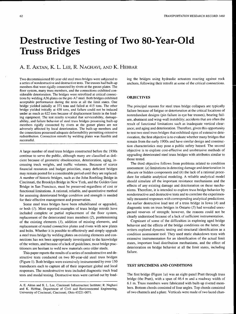
The first bridge (Figure la) was an eight-panel Pratt through truss bridge (the Pratt), with a span of 46.4 m and a roadway width of 6.1 m. Truss members were fabricated with built-up riveted members. Bottom chords consisted of four angles. Top chords consisted of two channels and a plate. Verticals were made of two laced chan-
Aktan etal.
(a) Pratt Truss Bridge
(b) Camelback Truss Bridge
FIGURE 1 Test bridges.
nels, and diagonal members were fabricated from four angles and a plate. The truss connections were constructed by gusset plates 8 mm thick and rivets 19 mm in diameter. The floor system consisted of main transverse girders, longitudinal stringers, and a wood deck. Interior stringers were I-sections 46 cm deep spaced 122 cm center to center. Exterior stringers were built up of angles and plates. Transverse floor girders were I-beams 76 cm deep. The truss was supported by rollers and hinges bearing on reinforced concrete abutments faced with sandstone.
The second bridge (Figure lb) was a 12-panel Camelback through truss bridge (the Camelback) 12 m high at the midspan, with a span of 76.2 m and a roadway width of 6.1 m. The construction of the Camelback was similar to that of the Pratt, with the exception that gusset plates were 11 mm thick and rivets were 22 mm in diameter.
Arms-Length Inspection
A hanging scaffold system was constructed along the lower chords and a cherry picker was used to reach the upper chords to enable visual inspections at close range. The inspections served to (a) verify that construction matched the available shop drawings; (b) document existing deterioration and damage on the members, connec-
63
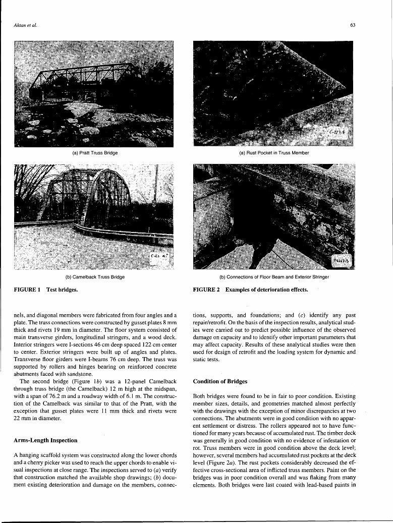
(a) Rust Pocket in Truss Member
(b) Connections of Floor Beam and Exterior Stringer
FIGURE 2 Examples of deterioration effects.
tions, supports, and foundations; and (c) identify any past repair/retrofit. On the basis of the inspection results, analytical studies were carried out to predict possible influence of the observed damage on capacity and to identify other important parameters that may affect capacity. Results of these analytical studies were then used for design of retrofit and the loading system for dynamic and static tests.
Condition of Bridges
Both bridges were found to be in fair to poor condition. Existing member sizes, details, and geometries matched almost perfectly with the drawings with the exception of minor discrepancies at two connections. The abutments were in good condition with no apparent settlement or distress. The rollers appeared not to have functioned for many years because of accumulated rust. The timber deck was generally in good condition with no evidence of infestation or rot. Truss members were in good condition above the deck level; however, several members had accumulated rust pockets at the deck level (Figure 2a). The rust pockets considerably decreased the effective cross-sectional area of inflicted truss members. Paint on the bridges was in poor condition overall and was flaking from many elements. Both bridges were last coated with lead-based paints in
64
1982. The most relevant damage specific to each bridge is discussed in the following sections.
Pratt
Bottom chords and the gusset plates had considerable rust at connections to the bearings. At the northeast bearing, 50 percent of the gusset plate cross section was gone. Interior stringers were in satisfactory condition, with less than 5 percent loss caused by rusting of the overall cross sections. Several interior stringers were not bearing on the abutment walls at both ends; however, connections to floor girders were satisfactory. Exterior stringers suffered from extensive rust and deterioration. Damage was caused by atmospheric effects accelerated by poor slope and deicing salts. Webs of stringers at both ends of panels had lost almost 100 percent of their cross sections (Figure 2b). Apparently, these stringers had lost all their load-carrying capacity and were held in place by the timber decks. Floor girders, in general, were in good condition, except for the end connections to trusses, where girders had lost 50 percent of the web area with missing or corroded rivets.
Camelback
Bottom chords on both trusses had lost some lacings at end panels. Rust was noticeable on the tips of built-up angles of bottom chords. The maximum area reduction caused by rust was approximately 15 percent of the total cross section. Interior stringers were in good condition, with less than 5 percent cross-section reduction caused by rust. Stringers were in satisfactory shape at the connections to the floor girders. Exterior stringers, however, were so deteriorated that they had lost more than 80 percent of their cross sections at the connections. Both ends of the floor girders exhibited considerable rust at connections to the trusses so that the loss of effective web and rivet cross-sectional areas was about 40 and 30 percent, respectively.
RESEARCH PROCEDURE
The research procedure was designed to fulfill the objectives while maintaining an acceptable cost. A considerable investment was already made in data acquisition and signal conditioning equipment, loading actuators, and servo-control systems in conjunction with an earlier study that incorporated nondestructive and destructive testing of a reinforced concrete slab bridge (6). To attain the main objective it was necessary to load the main trusses to extensive yielding and if possible, failure, while simulating progressively increasing truck loading. This required retrofit and a load transfer system. The retrofit was needed to prevent premature failures of floor girders and truss connections. The load transfer system was needed to transfer applied static loads generated by hydraulic actuators (up to 728 tons) through floor girders to truss members. It was desired to accomplish this while simulating single as well as multiple one-lane truck loading. One-lane loading was considered more probable for the test specimens and asymmetric failure modes were expected to be more critical than symmetric ones.
Material Properties
Some of the deteriorated and nonfunctional lower wind-bracing elements and plates were removed to fabricate material samples.
TRANSPORTATION RESEARCH RECORD 1460
Coupons were tested to determine the mechanical characteristics of the pre-A 7 material. Average values for the yield stress (Fy = 248 MPa), the modulus of elasticity (E = 207 GPa), as well as the yield plateau, strain-hardening characteristics, and the elongation capacity were found to be comparable to those for A 7 steel. Microstructural evaluation of the materiai was carried out on polished and etched samples using the scanning electron microscopy technique. Tests on the mechanical characteristics of the material were followed by welding tests to explore the weldability of A36 plates of comparable thickness to the bridge material. The microstructure of the welds was then investigated by various coupon tests to verify deformability and strength.
Nondestructive Dynamic Tests
Modal tests were carried out for structural identification and for exploring whether bridge flexibility obtained by processing modal test results serves as a condition and damage index ( 7 ). The structural identification studies served as a basis for designing the loading and instrumentation. Damage-detection studies, summarized elsewhere, verified that flexibility may serve as a damage-sensitive and objective structural condition index (8).
Loading System
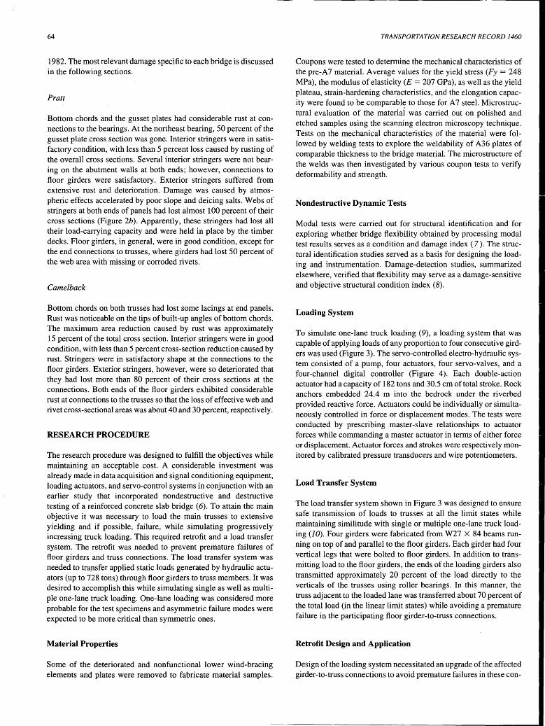
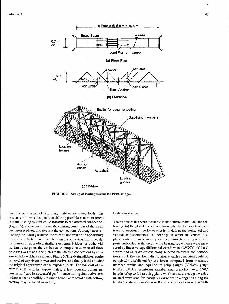
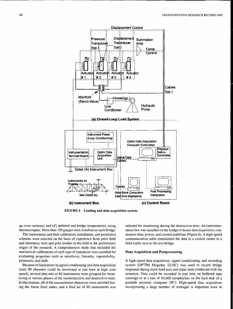
To simulate one-lane truck loading (9), a loading system that was capable of applying loads of any proportion to four consecutive girders was used (Figure 3). The servo-controlled electro-hydraulic system consisted of a pump, four actuators, four servo-valves, and a four-channel digital controller (Figure 4 ). Each double-action actuator had a capacity of 182 tons and 30.5 cm of total stroke. Rock anchors embedded 24.4 m into the bedrock under the riverbed provided reactive force. Actuators could be individually or simultaneously controlled in force or displacement modes. The tests were conducted by prescribing master-slave relationships to actuator forces while commanding a master actuator in terms of either force or displacement. Actuator forces and strokes were respectively monitored by. calibrated pressure transducers and wire potentiometers.
Load Transfer System
The load transfer system shown in Figure 3 was designed to ensure safe transmission of loads to trusses at all the limit states while maintaining similitude with single or multiple one-lane truck loading (10). Four girders were fabricated from W27 X 84 beams running on top of and parallel to the floor girders. Each girder had four vertical legs that were bolted to floor girders. In addition to transmitting load to the floor girders, the ends of the loading girders also transmitted approximately 20 percent of the load directly to the verticals of the trusses using roller bearings. In this manner, the truss adjacent to the loaded lane was transferred about 70 percent of the total load (in the linear limit states) while avoiding a premature failure in the participating floor girder-to-truss connections.
Retrofit Design and Application
Design of the loading system necessitated an upgrade of the affected girder-to-truss connections to avoid premature failures in these con-
Aktan et al. 65
I· 8 Panels @ 5.8 m = 46.4 m ·I
) Brace Beam Trusses
( 6.7m I g· } b t 71 c/c
Load Frame Girder
(a) Floor Plan
Actuator
7.3m I c/c
(b) Elevation
Exciter for dynamic testing
Anchor cables
(c) 3-DView
Stabilizing members
Loading girders
FIGURE 3 Set-up of loading system for Pratt bridge.
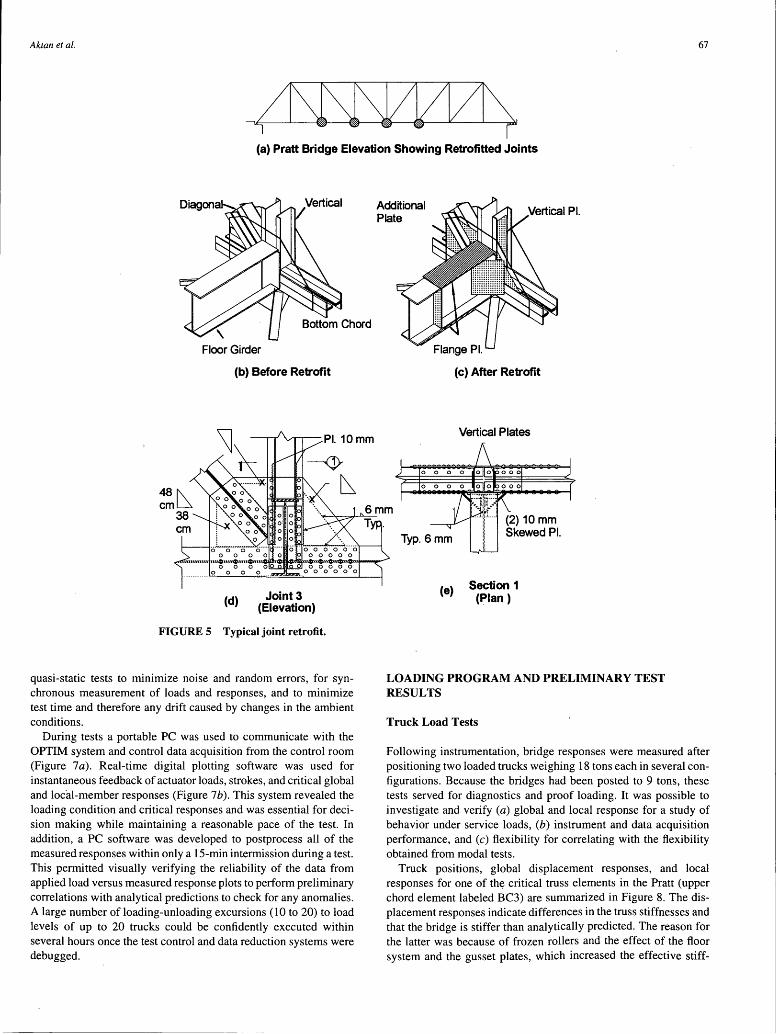
nections as a result of high-magnitude concentrated loads. The bridge retrofit was designed considering possible maximum forces that the loading system could transmit to the affected connections (Figure 5), also accounting for the existing conditions of the members, gusset plates, and rivets at the connections. Although necessitated by the loading scheme, the retrofit also created an opportunity to explore effective and feasible manners of treating extensive deterioration or upgrading similar steel truss bridges, or both, with minimal change on the aesthetics. A simple solution to all these problems was to add A36 plates to the affected connections by some simple fillet welds, as shown in Figure 5. This design did not require removal of any rivets, it was unobtrusive, and finally it did not alter the original appearance of the exposed joints. The low cost of the retrofit with welding (approximately a few thousand dollars per connection) and its successful performance during destructive tests indicated that a possibly superior alternative to retrofit with bolting/ riveting may be found in welding.
Instrumentation
The responses that were measured in the static tests included the following: (a) the global vertical and horizontal displacements at each truss connection at the lower chords, including the horizontal and vertical displacements at the bearings, in which the vertical displacements were measured by wire potentiometers using reference posts embedded in the creek while bearing movements were measured by linear voltage differential transformers (LVDTs); (b) local strains and axial distortions along selected members and connections, such that the force distribution at each connection could be completely established by the forces computed from measured member strains and equilibrium [clip gauges (30.5-cm gauge length), L VDTs (measuring member axial distortions over gauge lengths of up to 6.1 m using piano wire), and strain gauges welded on steel were used for these]; (c) variations in elongation along the length of critical members as well as strain distributions within built-
66 TRANSPORTATION RESEARCH RECORD 1460
,_. _. _. _. _. ___ -;---- _Q!~R~~.!TI~~!-~~mt!~! __ _____________ . __ _ i ~ · -· -·-· -· -· -n-· -· -·-· -· -r r · -· -- -- -· -·n· -·-·-·--- --· -· -· -· -· -·-· -
! ~ressure !! Dis~lacemen~ Summation !tfra duc~tr Trapsducer !i Amp. '(tw.) :· (tYP.) :: ~
ii Tr !flr'l!l ~r,-,,t92'°'
Cables "'=============tl(typ.)
Manifold (Servo-Valve)
Hydraulic Pump
J[ ___ . ___ . _. ______ (a) _Closed~Loop. Load System. __ -- ---- _. _____ -- . -. i!
ii if
Instrument Power (Loop Conditioning)
Optim Data Acquisition Unit
(b) Instrument Box (c) Control Room
FIGURE 4 Loading and data acquisition system.
up cross sections; and (d) ambient and bridge temperatures, using thermocouples. More than 150 gauges were installed on each bridge.
The instruments and their calibration,,installation, and protection schemes were selected on the basis of experience from prior field and laboratory tests and pilot studies in the field at the preliminary stages of the research. A comprehensive study that included the mechanical calibrations of each type of transducer was essential for evaluating properties such as sensitivity, linearity, repeatability, hysteresis, and drift.
Because of limitations in signal conditioning and data acquisition (only 80 channels could be monitored at one time at high scan speed), several data sets of 80 instruments were grouped for monitoring at various phases of the nondestructive and destructive tests. In this manner, all of the measurement objectives were satisfied during the linear limit states, and a final set of 80 instruments was
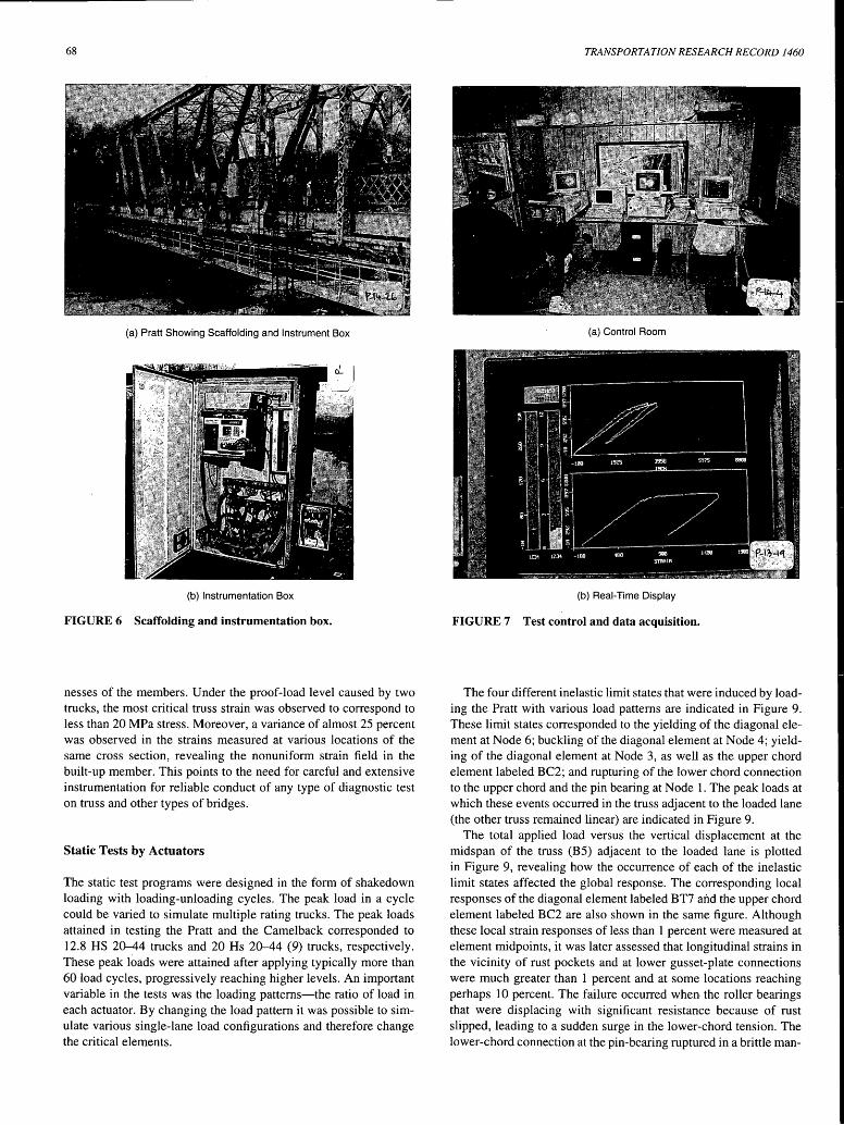
selected for monitoring during the destructive tests. An instrumentation box was installed on the bridge to house data acquisition, connection slots, power, and current stabilizer (Figure 6). A high-speed communication cable transmitted the data to a control center in a field trailer next to the test bridge.
Data Acquisition and Postprocessing
A high-speed data acquisition, signal conditioning, and recording system (OPTIM Megadac 221 OC) was used to record bridge responses during truck load tests and static tests conducted with the actuators. Data could be recorded in real time on buffered tape cartridge or at a rate of 20,000 samples/sec on the hard disk of a portable personal computer. (PC). High-speed data acquisition incorporating a large number of averages is important even in
Aktan et al. 67
(a) Pratt Bridge Elevation Showing Retrofitted Joints
Floor Girder
(b) Before Retrofit
(d) Joint 3 (Elevation)
FIGURE 5 Typical joint retrofit.
quasi-static tests to minimize noise and random errors, for synchronous measurement of loads and responses, and to minimize test time and therefore any drift caused by changes in the ambient conditions.
During tests a portable PC was used to communicate with the OPTIM system and control data acquisition from the control room (Figure 7a). Real-time digital plotting software was used for instantaneous feedback of actuator loads, strokes, and critical global and local-member responses (Figure 7b). This system revealed the loading condition and critical responses and was essential for decision making while maintaining a reasonable pace of the test. In addition, a PC software was developed to postprocess all of the measured responses within only a 15-min intermission during a test. This permitted visually verifying the reliability of the data from applied load versus measured response plots to perform preliminary correlations with analytical predictions to check for any anomalies. A large number of loading-unloading excursions (10 to 20) to load levels of up to 20 trucks could be confidently executed within several hours once the test control and data reduction systems were debugged.
Additional Plate
0 0
0 0
Typ. 6mm
(e)
(c) After Retrofit
Vertical Plates
(2) 10 mm Skewed Pl.
Section 1 (Plan)
LOADING PROGRAM AND PRELIMINARY TEST RESULTS
Truck Load Tests
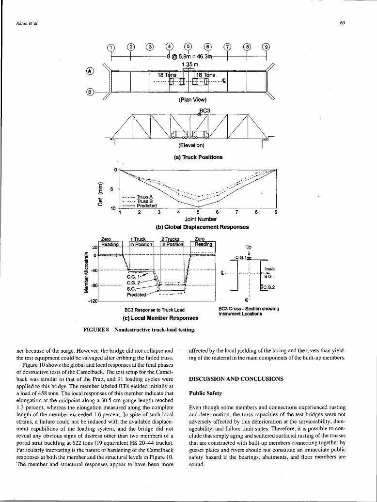
Following instrumentation, bridge responses were measured after positioning two loaded trucks weighing 18 tons each in several configurations. Because the bridges had been posted to 9 tons, these tests served for diagnostics and proof loading. It was possible to investigate and verify (a) global and local response for a study of behavior under service loads, (b) instrument and data acquisition performance, and (c) flexibility for correlating with the flexibility obtained from modal tests.
Truck positions, global displacement responses, and local responses for one of th¥ critical truss elements in the Pratt (upper chord element labeled BC3) are summarized in Figure 8. The displacement responses indicate differences in the truss stiffnesses and that the bridge is stiffer than analytically predicted. The reason for the latter was because of frozen rollers and the effect of the floor system and the gusset plates, which increased the effective stiff-
68
(a) Pratt Showing Scaffolding and Instrument Box
(b) Instrumentation Box
FIGURE 6 Scaffolding and instrumentation box.
nesses of the members. Under the proof-load level caused by two trucks, the most critical truss strain was observed to correspond to less than 20 MPa stress. Moreover, a variance of almost 25 percent was observed in the strains measured at various locations of the same cross section, revealing the nonuniform strain field in the built-up member. This points to the need for careful and extensive instrumentation for reliable conduct of any type of diagnostic test on truss and other types of bridges.
Static Tests by Actuators
The static test programs were designed in the form of shakedown loading with loading-unloading cycles. The peak load in a cycle could be varied to simulate multiple rating trucks. The peak loads attained in testing the Pratt and the Camelback corresponded to 12.8 HS 20-44 trucks and 20 Hs 20-44 (9) trucks, respectively. These peak loads were attained after applying typically more than 60 load cycles, progressively reaching higher levels. An important variable in the tests was the loading patterns-the ratio of load in each actuator. By changing the load pattern it was possible to simulate various single-lane load configurations and therefore change the critical elements.
TRANSPORTATION RESEARCH RECORD 1460
(a) Control Room
(b) Real-Time Display
FIGURE 7 Test control and data acquisition.
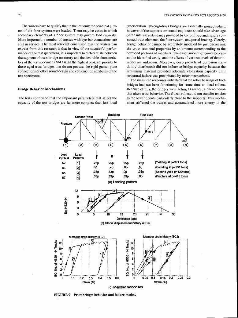
The four different inelastic limit states that were induced by loading the Pratt with various load patterns are indicated in Figure 9. These limit states corresponded to the yielding of the diagonal element at Node 6; buckling of the diagonal element at Node 4; yielding of the diagonal element at Node 3, as well as the upper chord element labeled BC2; and rupturing of the lower chord connection to the upper chord and the pin bearing at Node 1. The peak loads at which these events occurred in the truss adjacent to the loaded lane (the other truss remained linear) are indicated in Figure 9.
The total applied load versus the vertical displacement at the midspan of the truss (B5) adjacent to the loaded lane is plotted in Figure 9, revealing how the occurrence of each of the inelastic limit states affected the global response. The corresponding local responses of the diagonal element labeled BT7 and the upper chord element labeled BC2 are also shown in the same figure. Although these local strain responses of less than 1 percent were measured at element midpoints, it was later assessed that longitudinal strains in the vicinity of rust pockets and at lower gusset-plate connections were much greater than 1 percent and at some locations reaching perhaps 10 percent. The failure occurred when the roller bearings that were displacing with significant resistance because of rust slipped, leading to a sudden surge in the lower-chord tension. The lower-chord connection at the pin-bearing ruptured in a brittle man-
Aktan et al. 69
I r (a) Truck Positions
Joint Number (b) Global Displacement Responses
Zero 1 Truck 2 Trucks Zero
20 Readin
o~~~~
in Position in Position Readin Up
• ·-·-·--···-·
.8 i -80 ------· :::!
BC3 Response to Truck Load
~-·-J-~~1--~~de ! S.G . ;
! C.G.2 ~
~;
BC3 Cross - Section showing Instrument Locations
(c) Local Member Responses
FIGURE 8 Nondestructive truck-load testing.
ner because of the surge. However, the bridge did not collapse and the test equipment could be salvaged after cribbing the failed truss.
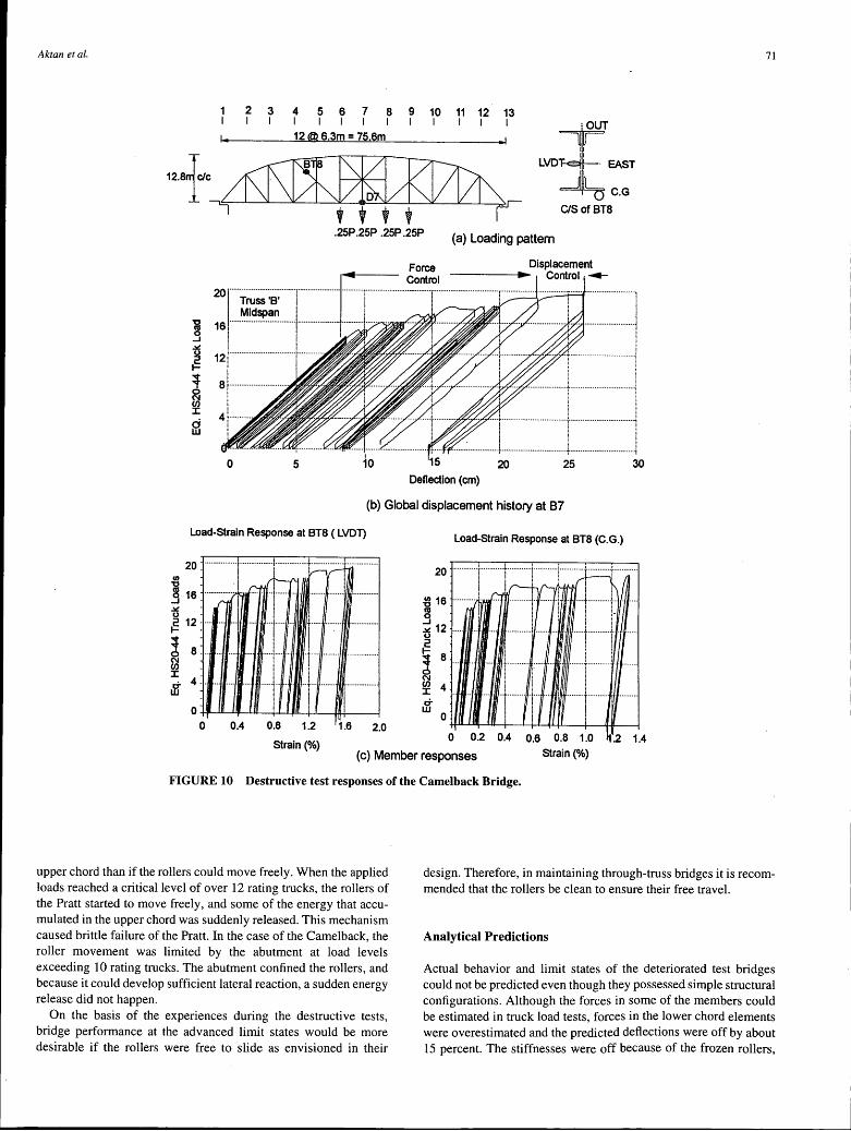
Figure 10 shows the global and local responses at the final phases of destructive tests of the Camelback. The test setup for the Camelback was similar to that of the Pratt, and 91 loading cycles were applied to this bridge. The member labeled BT8 yielded initially at a load of 458 tons. The local responses of this member indicate that elongation at the midpoint along a 30.5-cm gauge length reached 1.3 percent, whereas the elongation measured along the complete length of the member exceeded 1.6 percent. In spite of such local strains, a failure could not be induced with the available displacement capabilities of the loading system, and the bridge did not reveal any obvious signs of distress other than two members of a portal strut buckling at 622 tons (19 equivalent HS 20-44 trucks). Particularly interesting is the nature of hardening of the Camelback responses at both the member and the structural levels in Figure 10. The member and structural responses appear to have been more
affected by the local yielding of the lacing and the rivets than yielding of the material in the main components of the built-up members.
DISCUSSION AND CONCLUSIONS
Public Safety
Even though some members and connections experienced rusting and deterioration, the truss capacities of the test bridges were not adversely affected by this deterioration at the serviceability, damageability, and failure limit states. Therefore, it is possible to conclude that simply aging and scattered surfacial rusting of the trusses that are constructed with built-up members connecting together by gusset plates and rivets should not constitute an immediate public safety hazard if the bearings, abutments, and floor members are sound.
70
The writers have to qualify that in the test only the principal girders of the floor system were loaded. There may be cases in which secondary elements of a floor system may govern load capacity. More important, a number of trusses with eye-bar connections are still in service. The most relevant conclusion that the writers can extract from this research is that in view of the successful performance of the test specimens, it is important to differentiate between the segment of truss bridge inventory and the desirable characteristics of the test specimens and assign the highest program priority to those aged truss bridges that do not possess the rigid gusset-plate connections or other sound design and construction attributes of the test specimens.
Bridge Behavior Mechanisms
The tests confirmed that the important parameters that affect the capacity of the test bridges are far more complex than just local
Fracture
Load Cycle#
Load Patterns
··· ... ·· ..
' '
'
TRANSPORTATION RESEARCH RECORD 1460
deterioration. Through-truss bridges are externally nonredundant; however, if the supports are sound, engineers should take advantage of the internal redundancy provided by the built-up and rigidly connected truss elements, the floor system, and portal bracing. Clearly, bridge behavior cannot be accurately modeled by just decreasing the cross-sectional properties by an amount corresponding to the corroded portions of members. The exact amount of corrosion cannot be identified easily, and the effects of various levels of deterioration are unknown. Moreover, deep pockets of corrosion (randomly distributed) did not influence bridge capacity because the remaining material provided adequate elongation capacity until structural failure was precipitated by other mechanisms.
The measured responses indicated that the roller bearings of both bridges had not been functioning for some time as ideal rollers. Because of this, the bridges were acting as arches, a phenomenon that alters truss behavior. The frozen rollers did not transfer tension to the lower chords particularly close to the supports. This mechanism stiffened the trusses and accumulated more energy in the
First Yield
........ BT7
5
62
63
65
67
.25p
.6p .25p .25p .25p
.Op
.33p
.Op
(Yielding at p=371 tons)
(Buckling at p=231 tons) (Second yield p=420 tons) (Fracture at p=415 tons)
~ 12 2 .... 10 ..,. ..,. I 8
0 N 6 fl) J: 0 4 0
2 z d UJ
0.1
12
9
6
3
0
.33p
.33p
5
.4p .Op .33p .Op .33p .33p
(a) Loading pattern
10 15 20 25 Deflection (cm)
(b) Global displacement history at B 5
I I I I I I
----r----35
Member strain history (BC2)
"' ~ 12
~ 10 ..,. ..,. 8 I
0 N 6 fl) J: 'O 4 0
2 z d UJ
0.2 0.3 0.4 0.5 0.6 0.05 0.1 0.15 0.2 025
Strain(%) Strain(%)
(c) Member responses
FIGURE 9 Pratt bridge: behavior and failure modes.
0.3
Aktan et al. 71
2 3 4 5 6 7 8 9 10 11 12 13 I I I I I I I I I I I I
1. [email protected]=75.6m • 1 I:QUT
I
LVD EAST I
C.G
C/S of BT8
.25P .25P .25P .25P (a) Loading pattern
Deflection (cm)
(b) Global displacement history at 87
Load-Strain Response at BT8 ( LVDl) Load-Strain Response at BT8 (C.G.)
20 -················l················+··············+·······;;=t···· .......... . II) - I ,r--('. v-- I ~ 1s -·············A· r:. · ·· ······ ·· · ······· ...... .! :; I' f I I U I ! !
~ 1:_ _ __ -1 J r--------------
Ncn i ! J: i j
M :-- I I 111 l1-
20 ···········r········r········t···········1············t···········1············ I .
o 0.4 0.8 1.2 1.6 2.0 0 0.2 0.4 0.6 0.8 1.0 2 1.4
Strain(%) (c) Member responses Strain(%)
FIGURE 10 Destructive test responses of the Camelback Bridge.
upper chord than if the rollers could move freely. When the applied loads reached a critical level of over 12 rating trucks, the rollers of the Pratt started to move freely, and some of the energy that accumulated in the upper chord was suddenly released. This mechanism caused brittle failure of the Pratt. In the case of the Camelback, the roller movement was limited by the abutment at load levels exceeding 10 rating trucks. The abutment confined the rollers, and because it could develop sufficient lateral reaction, a sudden energy release did not happen.
On the basis of the experiences during the destructive tests, bridge performance at the advanced limit states would be more desirable if the rollers were free to slide as envisioned in their
design. Therefore, in maintaining through-truss bridges it is recommended that the rollers be clean to ensure their free travel.
Analytical Predictions
Actual behavior and limit states of the deteriorated test bridges could not be predicted even though they possessed simple structural configurations. Although the forces in some of the members could be estimated in truck load tests, forces in the lower chord elements were overestimated and the predicted deflections were off by about 15 percent. The stiffnesses were off because of the frozen rollers,
72
effects of the floor and portal bracing systems, and the gusset plates, which reduced the effective length of the members. The capacities of the test bridges could not be predicted without conducting the experimental studies. Failure modes (the brittle failure of the Pratt and buckling of strut members of the Camelback) and some important mechanisms (variations in the strain field within a cross_ section, variation of post-yielding strains along the deteriorated members, post-yield hardening in built-up latticed members caused by lattice yielding) could not be predicted without destructive testing.
Fastening the timber floor system to the steel beams not only considerably increased the vertical stiffness of the deck but also significantly contributed to the lateral stability of the bridge at the deck level. Such a floor system could eliminate the need for bottom x-bracings. Elimination of x-bracings is a valuable consideration because typically these are the most deteriorated elements of older truss bridges.
Retrofit
The Pratt and Camelback resisted total loads equivalent to 12.8 and 19 HS20-44 trucks, respectively. After completion of each destructive test, no evidence of distortion or failure was found at the connections that were retrofit. The effectiveness of the retrofit was demonstrated under the heavy concentrated loads that the connections experienced during destructive testing. Therefore, it is concluded that it should be possible to retrofit similar bridges up to acceptable levels of safety with minimal effort and cost. Truss connections may be upgraded easily by inserting properly designed triangular plates that are welded to truss members behind the existing gussets. This method maintains the aesthetics and the original appearance of the joints while providing the extra strength needed to assist deteriorated rivets and gusset plates. In the case of rivet deterioration alone, lines of simple fillet welds between a healthy gusset and the truss member may be sufficient to compensate for rivet (fastener) losses. ·
The bottom chords of most older trusses are designed to be slimmer than the top chord, and they are generally more vulnerable to deterioration because of their geometric position and tensile strain. To reduce the risk of failure in a deteriorated bottom chord, additional redundancy would be desirable. High-strength cables posttensioned alongside and parallel to the bottom chord may provide redundancy. In the Pratt, only the end panels of the bottom chords were posttensioned by cables. A continuous posttensioned cable extending all the way along the bottom chord would have been more effective.
TRANSPORTATION RESEARCH RECORD 1460
ACKNOWLEDGMENTS
Research has been conducted at the Cincinnati Infrastructure Institute with support provided by the Ohio Department of Transportation (ODOT), FHWA, the National Science Foundation (NSF), and the Franklin County Engineer. The writers express their appreciation to Messrs Edwards, Dalal, Hanhilammi, and Barnhart of ODOT, Mr. Sherman of Franklin County, Mr. Shamis of Ohio FHWA, and Dr. Chong of NSF for their encouragement and support. Corporate assistance was provided by GOETTLE, OPTIM Megadac, SCHENK-PEGASUS, and PCB Piezotronics. Excellent support was provided by CII research support personnel and many graduate students.
REFERENCES
1. Sessions, L., B. Blanchard, and J. Locke. Over the Hill Bridges. Journal of Modern Steel Construction, Vol. 33, No. 2. American Institute of Steel Construction, Feb. 1993.
2. Klaiber, F. W., K. F. Dunker, T. J. Wipf, and W.W. Sanders, Jr. Methods of Strengthening Existing Highway Bridges. In Transportation Research Board.293, TRB, National Research Council, Washington, D.C., 1987.
3. Special Report 222: Bridges on Secondary Highways and Local Roads, Rehabilitation and Replacement. TRB, National Research Council, Washington, D.C., 1980.
4. Klaiber, F. W., W.W. Sanders, and H. A. Elleby, NCHRP Report 607: Ultimate Load Test of a High-Truss Bridge. TRB, National Research Council, Washington, D.C., 1976.
5. Bakht, B., and L. G. Jaeger. Bridge Testing: A Surprise Every Time. ASCE Journal of Structural Engineering, Vol. 116, No. 5, 1990.
6. Aktan, A. E., M. J. Zwick, R. A. Miller, and B. M. Shahrooz. Nondestructive and Destructive Testing of a Decommissioned RC Slab Highway Bridge and Associated Analytical Studies. In Transportation Research Record 1371, TRB, National Research Council, Washington, D.C., 1993.
7. Aktan, A. E., K. L. Lee, and V. Dalal. Multireference Modal Testing For Bridge Diagnostics. Proc., Structural Materials Technology, NDT Conference, New Jersey DOT and FHWA, Feb. 1994.
8. Aktan, A. E., K. L. Lee, C. Chuntavan, S. Hosahalli, and T. Aksel. Modal Testing For Structural Identification and Condition Assessment of Constructed Facilities. Proc., 12th International Modal Analysis Conference, Honolulu, Hawaii, Jan. 1994.
9. Standard Specifications of Highway Bridges, 14th ed. AASHTO, Washington, D.C., 1989.
10. Guide Specifications for Strength Evaluation of Existing Steel and Concrete Bridges. Washington, D.C., 1992.
Publication of this paper sponsored by Committee on Dynamics and Field Testing of Bridges.