detailed rules - world robot summit
TRANSCRIPT
WRS Tunnel Disaster Response and Recovery Rulebook Ver.2.2.3 1/24
6/9/2021
WRS Tunnel Disaster Response and
Recovery Challenge
Rule Book (Ver.2.2.3)
WRS Task Development Team
Competition Overview
1. Competition
1.1. Mission and Task Codes, Types and Times
1.1.1. The types and times for each mission in the WRS Tunnel Disaster Response and Recovery Challenge
are as follows.
1.1.1.1. Mission times may change
1.1.1.2. Even if the simulation time is delayed, teams cannot continue to compete once the mission
time (actual time) is over.
(The actual time indicates the end of the mission.)
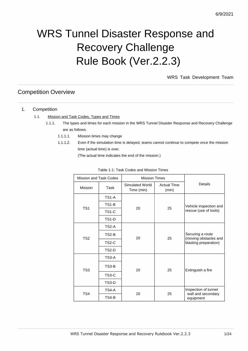
Table 1-1: Task Codes and Mission Times
Mission and Task Codes Mission Times
Details Mission Task
Simulated World
Time (min)
Actual Time
(min)
TS1
TS1-A
20 25 Vehicle inspection and rescue (use of tools)
TS1-B
TS1-C
TS1-D
TS2
TS2-A
20 25 Securing a route (moving obstacles and blasting preparation)
TS2-B
TS2-C
TS2-D
TS3
TS3-A
20 25 Extinguish a fire TS3-B
TS3-C
TS3-D
TS4 TS4-A
20 25 Inspection of tunnel wall and secondary equipment TS4-B
WRS Tunnel Disaster Response and Recovery Rulebook Ver.2.2.3 2/24
1.2. Number of Attempts
1.2.1. Each team can carry out all of the mission tasks once during the competition.
1.3. Competitors and Their Numbers
1.3.1. Registered team members who operate the robot(s) and carry out the mission tasks are referred to as
‘Competitors’.
1.3.1.1. Up to 2 competitors are allowed per team.
1.3.1.2. Only 1 competitor may operate the robot.
1.3.1.2.1. However, if 2 or more robots are used collaboratively to complete the task, these 2
robots may be operated by 2 competitors.
■ Examples of tasks where collaboration is acceptable.
Ex. 1) The second robot removes debris
Ex. 2) A camera mounted on a drone (UAV) gives a bird’s eye view of the
ground robot and its operation.
■ Example of tasks where collaboration is unacceptable.
Ex. 1) Two robots perform different tasks at the same time. E.g., 2 robots
remove one piece of debris.
Ex. 2) The drone (UAV) creates a 3D map, while the ground robot carries
out the task.
1.3.2. During the mission the competitors cannot swap with other team members.
1.3.3. Team members other than the competitors are not allowed to enter the control area (team booth) and
operate the robot(s) during the mission (tasks).
1.3.3.1. During the missions, competitors may not communicate with other team members.
1.3.4. Competitors and other team members can prepare for the mission start and restart, but during
preparations only 1 team member other than the competitors may enter the control area.
1.4. Referees and Competition Organisers
1.4.1. Referees
1.4.1.1. Referees manage the competition, decide the score etc. and monitor the time.
1.4.1.1.1. During the mission, each team has 1 main referee and 1 or more assistant referees
to give instructions and to judge.
1.4.1.2. Referees will make decisions concerning competition system malfunctions (network,
computer etc.)
1.4.1.2.1. If a problem during the mission is thought to be caused by a competition system
malfunction, competitors must alert a referee.
1.4.2. Competition Organisers
1.4.2.1. Competition organisers manage the competition and the referees.
1.4.2.2. The competition committee has a committee leader who is responsible for the overall
competition.
WRS Tunnel Disaster Response and Recovery Rulebook Ver.2.2.3 3/24
2. Robot(s)
2.1. Number of Robots
2.1.1. Only robots which have passed the stage gate examinations may be used in the competition.
2.1.2. There is no limit to the number of robots that can be used throughout all the missions.
2.1.2.1. Teams cannot continue to compete once the mission time (actual time) is over.
2.1.3. The same robot(s) must be used for the entirety of every mission.
2.2. Types of Robot
2.2.1. Platform robots or original robots created by the team may be used in the competition.
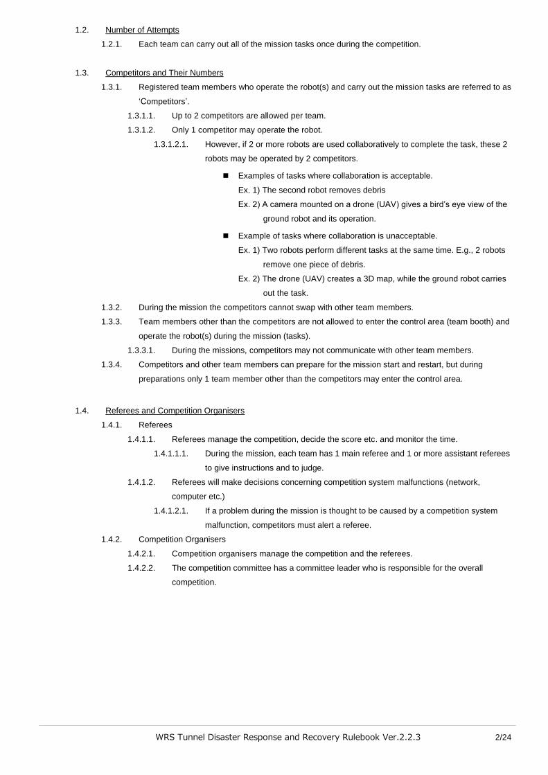
2.2.1.1. Below are the 2 types of platform robot.
※ Refer to the robot model for details (released separately)
【Leg-type Robot】
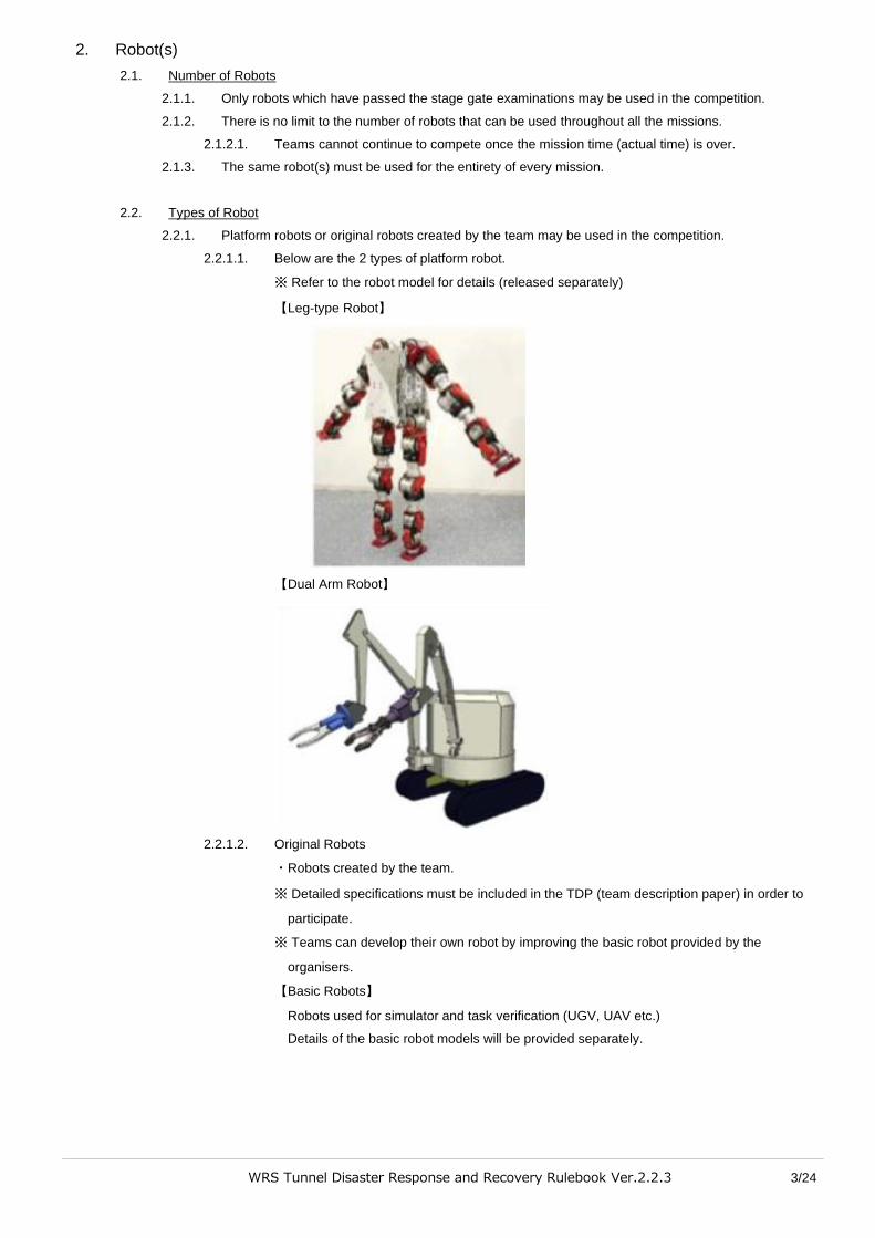
【Dual Arm Robot】
2.2.1.2. Original Robots
・Robots created by the team.
※ Detailed specifications must be included in the TDP (team description paper) in order to
participate.
※ Teams can develop their own robot by improving the basic robot provided by the
organisers.
【Basic Robots】
Robots used for simulator and task verification (UGV, UAV etc.)
Details of the basic robot models will be provided separately.

WRS Tunnel Disaster Response and Recovery Rulebook Ver.2.2.3 4/24
2.3. Robot Size and the Missions
2.3.1. The set field differs depending on the size of the robots used in the competition.
2.3.2. Robots are divided into 3 sizes.
【S size】
A robot that can pass though equilateral triangular hole with sides of 60cm.
【M size】
A robot that can pass through a square hole with sides of 80cm
【L size】
Any robots larger than a M size robot.

WRS Tunnel Disaster Response and Recovery Rulebook Ver.2.2.3 5/24
3. Field
3.1. The Field Location
3.1.1. A road running through a tunnel with 2 lanes of 2-way traffic. Each lane is 3.6m wide, and there are 1m
wide lay-bys on each side. The distance from the start to the goal depends on the task, but all tasks
take place within the tunnel.
3.2. Direction and Coordinates
3.2.1. The point at the center of the start line is the origin of the coordinates.
3.2.2. The coordinate system is a right-handed system with (+) X coordinated from the origin toward the red
pole, and (+) Z coordinates upward.
3.2.3. The (+) direction of the Y coordinate is forward, and the (-) direction is backward.
WRS Tunnel Disaster Response and Recovery Rulebook Ver.2.2.3 6/24
4. Start and Goal
4.1. Mission and Start
4.1.1. In general, each mission or task begins at the ‘start’.
4.2. Gates and Lines
4.2.1. Gates made up of a red pole and a blue pole are set at the start point, goal point and at each of the
check points.
4.2.2. Each gate has a flag with a number in order from [1], and this is called the gate number (gate No.).
4.2.3. A line running from the right pole to the left pole in the center of the gate is called the gate line (these
lines are numbered according to the gate number, i.e., Gate No.1 line).
4.2.3.1. The gate line at the start of each mission (or task) is called the start line.
4.2.3.2. The gate line at the check points for each mission (or task) are called the check point lines.
4.2.3.3. The gate line at the goal point for each mission (or task) is called the goal line.
4.2.3.4. The robot must start from the starting point, pass through the check point gates in numerical
order, and reach the gate at the goal point.
4.2.3.5. The red pole should be on the right of the robot as it crosses over each gate line.
4.3. Mission Times
4.3.1. The mission times are as indicated in Table. 1-1.
4.3.1.1. Teams cannot continue to compete once the actual time is over.
4.3.2. The mission time includes preparation time (including the preparation after a restart.)
4.4. Start
4.4.1. The robot’s start position is an arbitrary point behind the start line.
4.4.1.1. The robot cannot make any physical movements before starting.
4.4.1.1.1. Gathering information about the competition field beyond the start line by using
sensors etc. is not allowed before starting the mission.
4.4.2. No part of the robot is allowed over the start line (including the air space above the line) before the
mission starts.
4.4.3. The procedure for starting the mission is as follows.
4.4.3.1. The competitors will place any equipment needed for operating the robot on the table of the
control area.
4.4.3.2. When the referee gives the signal to start, begin preparations and start the mission.
4.4.3.2.1. Preparations include connecting the PC for operating the robot and the PC for the
simulation server.
4.4.4. Once the start signal has been given, the mission timer will begin.
4.5. Goal
4.5.1. The goal is passed when the referee confirms that the robot’s marker has crossed the goal line.
4.5.1.1. If 2 robots are used, then they have passed the goal when the referee confirms that both
robot’s markers have crossed the goal line.
4.5.2. The robot’s marker is a ball attached to the robot. This ball should be in a position on the robot that is
clearly visible to the referees.
4.5.2.1. The model for this ball will be released along with the field model.
4.5.3. Once reaching the goal, the mission (task) is over, and the timer is stopped.
WRS Tunnel Disaster Response and Recovery Rulebook Ver.2.2.3 7/24
4.5.3.1. When 2 robots are used, once both robots have reached the goal, the mission (task) is over
and the timer is stopped.
4.5.4. The goal can be reached without performing all the tasks, such as target recognition etc., required for
each mission (task).
4.5.4.1. However, in this case, points will not be received for uncompleted tasks.
4.5.4.2. Bonus score (for time) will also not be added.
※ For bonus score (time) please see 6.3.5.
4.6. Check Points
4.6.1. Check points are placed between the start and the goal.
4.6.2. Check points are passed when the referee confirms that the robot’s marker has crossed the check
point line.
4.6.2.1. When 2 robots are used, then the check points have been passed when the referee confirms
that both robot markers have crossed the check point line.
4.7. Restarts
4.7.1. Competitors can apply for a restart.
4.7.1.1. A restart is when after starting the mission, the team starts again from the beginning or check
point.
4.7.1.2. When restarting, the start procedure must be followed.
4.7.1.2.1. When restarting, the field must also be returned to the original state at the start.
4.7.2. Restart preparations can begin once the restart has been applied for and is accepted by the referee.
4.7.2.1. Restarts accepted by the referee cannot be undone.
4.7.2.2. If the team applies for abstention after the restart is accepted, they do not need to proceed
with the restart.
4.7.3. A restart may be applied for at the competitor’s convenience.
4.7.3.1. When restarting, any line (start line, check point line) in the system behind the position where
the restart was applied for may be used as the restart line.
4.7.3.1.1. These optional lines will differ depending on the mission.
4.7.3.2. Any points gained or lost in the area behind the restart line will be kept.
4.7.3.3. Any points gained or lost beyond the restart line will be reset.
4.7.4. Once the restart has been accepted the timer will be paused, and the field will be reset to its original
state. The restart will begin when the referees judge it to be ready, and the timer will continue.
4.7.5. The mission time after a restart will be calculated by subtracting the time when the referee accepts the
restart from the set mission time.
Ex.) The set time is 10 min. If the restart is accepted at 4 min 30 sec, then after the restart the
remaining mission time is 5 min 30 sec.
4.7.6. There is no limit to the number of restarts allowed.
4.7.7. If the referee judges a restart to be necessary then the team must restart. This is called a forced
restart.
4.8. Abstention
4.8.1. Competitors may abstain from all or part of a mission (task).
4.8.1.1. Competitors must apply to the referees for an abstention.
4.8.2. If an abstention takes place in the middle of a mission and any check point lines have been crossed,
the score earned up until the check points will be kept.
E.g.) Task A and B are carried out in succession. Task A is completed but the team abstain in the
middle of task B. Only the points from task A are kept.
WRS Tunnel Disaster Response and Recovery Rulebook Ver.2.2.3 8/24
5. Targets
5.1. About Tartgets
5.1.1. Targets are made from QR codes and pipes. The QR code size and pipe length of the “targets” are as
follows.
Table: 5-1 Target types and codes
Target Code QR Code Width (mm)
140 35 7
Pipe Length
(mm)
0 140-0 35-0 7-0
50 140-50 35-50 7-50
100 140-100 35-100 7-100
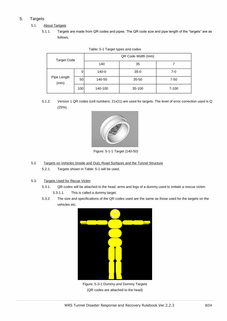
5.1.2. Version 1 QR codes (cell numbers: 21x21) are used for targets. The level of error correction used is Q
(25%).
Figure: 5-1-1 Target (140-50)
5.2. Targets on Vehicles (Inside and Out), Road Surfaces and the Tunnel Structure
5.2.1. Targets shown in Table: 5-1 will be used.
5.3. Targets Used for Recue Victim
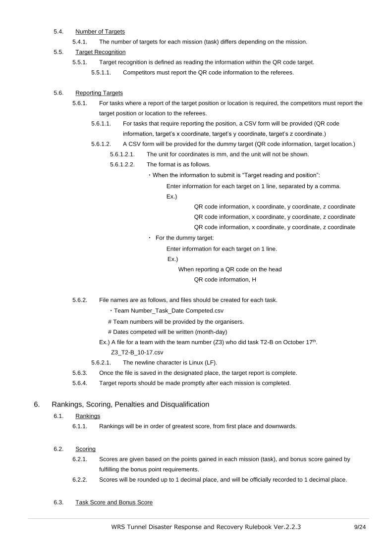
5.3.1. QR codes will be attached to the head, arms and legs of a dummy used to imitate a rescue victim.
5.3.1.1. This is called a dummy target.
5.3.2. The size and specifications of the QR codes used are the same as those used for the targets on the
vehicles etc.
Figure: 5-3-1 Dummy and Dummy Targets
(QR codes are attached to the head)
WRS Tunnel Disaster Response and Recovery Rulebook Ver.2.2.3 9/24
5.4. Number of Targets
5.4.1. The number of targets for each mission (task) differs depending on the mission.
5.5. Target Recognition
5.5.1. Target recognition is defined as reading the information within the QR code target.
5.5.1.1. Competitors must report the QR code information to the referees.
5.6. Reporting Targets
5.6.1. For tasks where a report of the target position or location is required, the competitors must report the
target position or location to the referees.
5.6.1.1. For tasks that require reporting the position, a CSV form will be provided (QR code
information, target’s x coordinate, target’s y coordinate, target’s z coordinate.)
5.6.1.2. A CSV form will be provided for the dummy target (QR code information, target location.)
5.6.1.2.1. The unit for coordinates is mm, and the unit will not be shown.
5.6.1.2.2. The format is as follows.
・When the information to submit is “Target reading and position”:
Enter information for each target on 1 line, separated by a comma.
Ex.)
QR code information, x coordinate, y coordinate, z coordinate
QR code information, x coordinate, y coordinate, z coordinate
QR code information, x coordinate, y coordinate, z coordinate
・ For the dummy target:
Enter information for each target on 1 line.
Ex.)
When reporting a QR code on the head
QR code information, H
5.6.2. File names are as follows, and files should be created for each task.
・Team Number_Task_Date Competed.csv
# Team numbers will be provided by the organisers.
# Dates competed will be written (month-day)
Ex.) A file for a team with the team number (Z3) who did task T2-B on October 17th.
Z3_T2-B_10-17.csv
5.6.2.1. The newline character is Linux (LF).
5.6.3. Once the file is saved in the designated place, the target report is complete.
5.6.4. Target reports should be made promptly after each mission is completed.
6. Rankings, Scoring, Penalties and Disqualification
6.1. Rankings
6.1.1. Rankings will be in order of greatest score, from first place and downwards.
6.2. Scoring
6.2.1. Scores are given based on the points gained in each mission (task), and bonus score gained by
fulfilling the bonus point requirements.
6.2.2. Scores will be rounded up to 1 decimal place, and will be officially recorded to 1 decimal place.
6.3. Task Score and Bonus Score

WRS Tunnel Disaster Response and Recovery Rulebook Ver.2.2.3 10/24
6.3.1. Each mission will have set tasks for the “task score”.
6.3.1.1. The task score is gained by completing these tasks.
6.3.2. Bonus score (tasks): Gained for certain requirements such as the task difficulty level, field
environment, and conditions set in each mission (task). (See 7.1.3).
6.3.2.1. The bonus score will be added only if the task score is also gained.
6.3.2.2. The bonus (task) score total will be calculated by multiplying the task score by a coefficient of
0.1 ~ 2.0.
6.3.2.2.1. This is called the bonus score coefficient.
6.3.3. Bonus score (environment): Gained when environmental information about the competition field is
submitted (maps, temperatures etc.)
6.3.3.1. Submit 3D environmental information such as maps and temperatures in a standard point
cloud data format.
6.3.4. Bonus score (time): Gained according to the time taken for each mission (task).
6.3.4.1. The score will be added if the goal is reached in a faster time than the mission time for each
mission (task).
6.3.4.1.1. The remaining time for the bonus score is measured in seconds, and 2/60 points are
added for each second.
E.g.) When 1min 34sec remain, 94sec × 2/60 points = 3.1 score
■ The number of points added for bonus score (time) may change.
6.3.4.2. When tools are used, if these tools are not brought to the goal, then the bonus score above
will not be given.
6.3.5. Penalties
6.3.5.1. For some missions (tasks) certain actions will incur penalties. If these actions are performed
then a set number of points will be deducted.
6.3.5.1.1. Even for missions (tasks) without actions that incur penalties, if the referee believes
an action deserves a penalty, then points will be deducted.
■ After the referee’s judgement, the lead referee will decide if points will be
deducted or not.
6.3.5.1.2. Actions that incur penalties and the number of points deducted will be released.
6.4. Disqualification and Misconduct
6.4.1. Conditions for disqualification
6.4.1.1. Teams will be disqualified if any of the following apply.
6.4.1.1.1. If clear misconduct was repeatedly confirmed by referees.
6.4.1.1.2. Misconduct can apply to competition methods, robots, tools etc.
6.4.1.1.3. Instructions by the referees and competition committee at and during the
competition are not followed.
6.4.1.2. In the case of disqualification, it will be explained to all participants (team leaders: 1 person
per team) who will give their opinions, and after a discussion by the referees and competition
committee members, the committee leader will decide on the disqualification.
6.4.2. Competing After Disqualification
6.4.2.1. When disqualified, the competition will end, and the team can no longer compete.
6.4.2.2. When disqualified, all points will be lost and the official record will be “disqualified”.
6.4.3. Misconduct
6.4.3.1. If the referee judges there to be clear misconduct, the mission will be forcibly stopped.
6.4.3.1.1. If a competition is forcibly stopped, the score for that mission will be lost.
WRS Tunnel Disaster Response and Recovery Rulebook Ver.2.2.3 11/24
■ In this case, the area of misconduct will be explained to all participants
(team leaders: 1 person per team) who will give their opinions, and after a
discussion by the referees and committee members and committee leader
will decide on a response.
6.4.3.1.2. If the referee judges that the cause for the mission to be forcibly stopped has been
resolved, then this mission may be attempted again, and teams can continue to
compete in further missions.
WRS Tunnel Disaster Response and Recovery Rulebook Ver.2.2.3 12/24
Mission T: Tunnel Disaster Response and Recovery
7. Missions
7.1. Common Score for All Missions
7.1.1. The tasks described in each mission indicate the basic technology required to complete the mission.
7.1.2. A map of the competition field will not be provided before the start of the mission in order to emulate
the site of a disaster.
7.1.2.1. The field environment and conditions may change depending on robot’s location or the time
etc., even in the same mission.
7.1.3. Below are the parameters for the competition field environment and conditions.
● Uneven road surface and amount of space (see appendix)
● Amount of light
● Wireless conditions
● Field of vision
● Other factors that will hinder the robot’s movements
7.1.4. Use of Tools
7.1.4.1. Tasks must be carried out using tools or functions that are permanently attached to the robot.
7.1.4.1.1. Robots can use tools provided in the competition field.
7.1.4.2. Robots should use simple tools for missions (tasks) when necessary. Simple tools are those
that do not have advanced mechanisms, such as a stand, or a camera attached to the end of
a long pole.
7.1.4.3. Simple tools used should be carried from the mission start, and brought to the goal.
WRS Tunnel Disaster Response and Recovery Rulebook Ver.2.2.3 13/24
7.2. 【TS1】: Vehicle Inspection and Rescue (Using Tools)
7.2.1. Details
Carry out an inspection of both the inside of the vehicle and the outside, as well as the surrounding
area. Using the designated tools, open the door, detach the door from the vehicle and remove the
victim.
7.2.1.1. The inspection consists of recognising targets and reporting their locations.
7.2.1.1.1.
7.2.1.2. The designated tool is a spreader with a mass of about 15kg.
7.2.2. Perform the following 3 tasks.
7.2.2.1. 【TS1-A】Inspect the outside of the vehicle and the surrounding area.
Recognise targets placed in the area surrounding the vehicle (road), and on the outside of the
vehicle itself, and report.
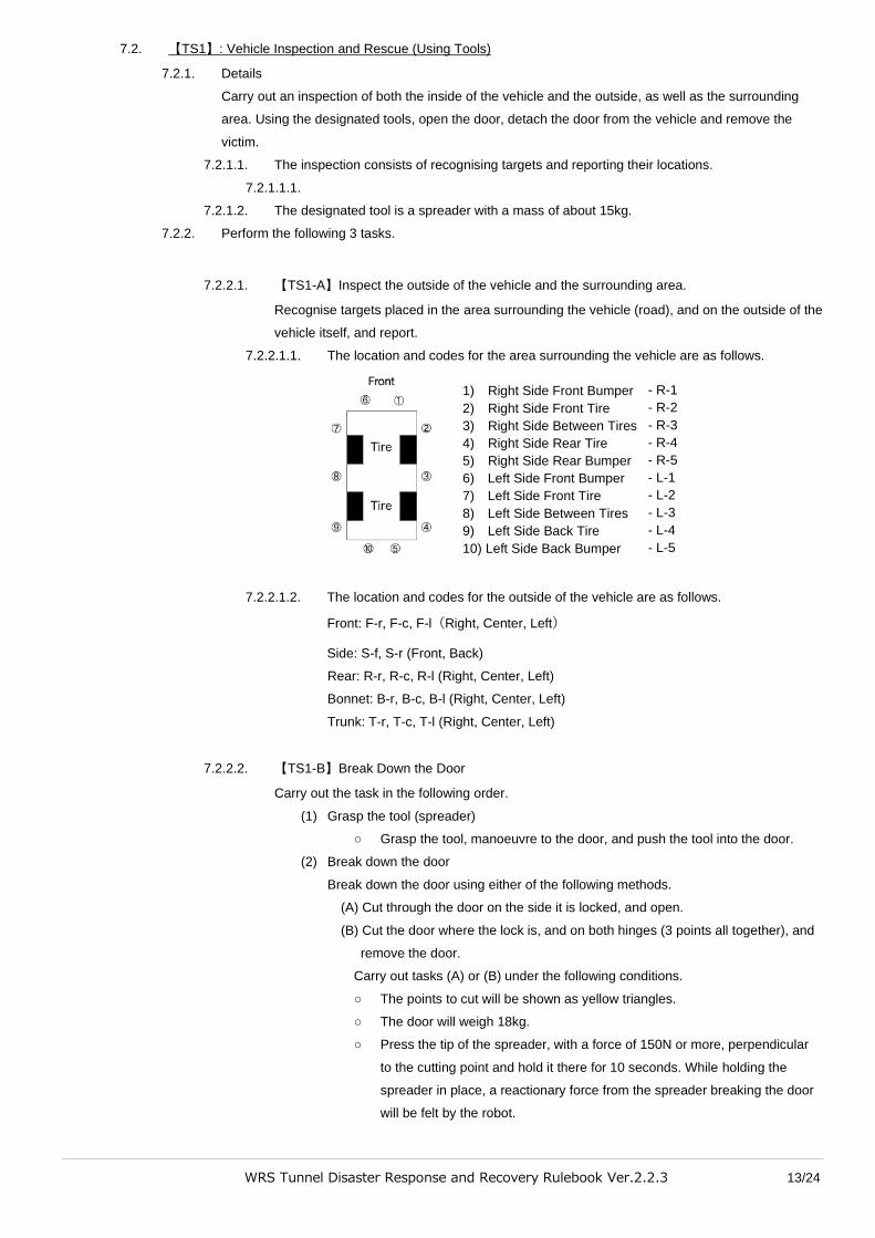
7.2.2.1.1. The location and codes for the area surrounding the vehicle are as follows.
7.2.2.1.2. The location and codes for the outside of the vehicle are as follows.
Front: F-r, F-c, F-l(Right, Center, Left)
Side: S-f, S-r (Front, Back)
Rear: R-r, R-c, R-l (Right, Center, Left)
Bonnet: B-r, B-c, B-l (Right, Center, Left)
Trunk: T-r, T-c, T-l (Right, Center, Left)
7.2.2.2. 【TS1-B】Break Down the Door
Carry out the task in the following order.
(1) Grasp the tool (spreader)
○ Grasp the tool, manoeuvre to the door, and push the tool into the door.
(2) Break down the door
Break down the door using either of the following methods.
(A) Cut through the door on the side it is locked, and open.
(B) Cut the door where the lock is, and on both hinges (3 points all together), and
remove the door.
Carry out tasks (A) or (B) under the following conditions.
○ The points to cut will be shown as yellow triangles.
○ The door will weigh 18kg.
○ Press the tip of the spreader, with a force of 150N or more, perpendicular
to the cutting point and hold it there for 10 seconds. While holding the
spreader in place, a reactionary force from the spreader breaking the door
will be felt by the robot.
1) Right Side Front Bumper
2) Right Side Front Tire
3) Right Side Between Tires
4) Right Side Rear Tire
5) Right Side Rear Bumper
6) Left Side Front Bumper
7) Left Side Front Tire
8) Left Side Between Tires
9) Left Side Back Tire
10) Left Side Back Bumper
- R-1
- R-2
- R-3
- R-4
- R-5
- L-1
- L-2
- L-3
- L-4
- L-5
WRS Tunnel Disaster Response and Recovery Rulebook Ver.2.2.3 14/24
○ If the position and angle of the tip of the spreader is correct, a yellow
indicator will appear near the spreader and will turn red after 3 seconds.
○ The margin for error in coordinates is ±30mm for position and ±5° for angle.
7.2.2.3. 【TS1-C】Inspection of the inside of the vehicle, and inspection of the victim.
Recognise the targets inside the vehicle, and the dummy targets, and report.
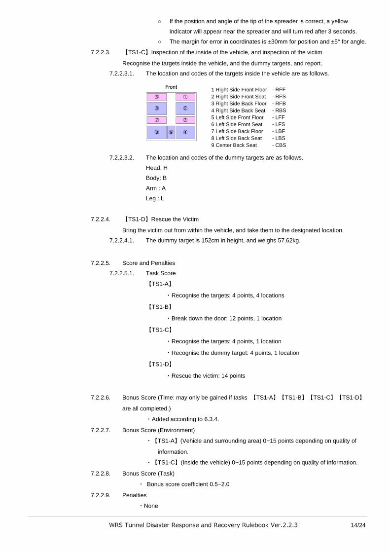
7.2.2.3.1. The location and codes of the targets inside the vehicle are as follows.
7.2.2.3.2. The location and codes of the dummy targets are as follows.
Head: H
Body: B
Arm : A
Leg : L
7.2.2.4. 【TS1-D】Rescue the Victim
Bring the victim out from within the vehicle, and take them to the designated location.
7.2.2.4.1. The dummy target is 152cm in height, and weighs 57.62kg.
7.2.2.5. Score and Penalties
7.2.2.5.1. Task Score
【TS1-A】
・Recognise the targets: 4 points, 4 locations
【TS1-B】
・Break down the door: 12 points, 1 location
【TS1-C】
・Recognise the targets: 4 points, 1 location
・Recognise the dummy target: 4 points, 1 location
【TS1-D】
・Rescue the victim: 14 points
7.2.2.6. Bonus Score (Time: may only be gained if tasks 【TS1-A】【TS1-B】【TS1-C】【TS1-D】
are all completed.)
・Added according to 6.3.4.
7.2.2.7. Bonus Score (Environment)
・【TS1-A】(Vehicle and surrounding area) 0~15 points depending on quality of
information.
・【TS1-C】(Inside the vehicle) 0~15 points depending on quality of information.
7.2.2.8. Bonus Score (Task)
・ Bonus score coefficient 0.5~2.0
7.2.2.9. Penalties
・None
1 Right Side Front Floor 2 Right Side Front Seat 3 Right Side Back Floor
4 Right Side Back Seat 5 Left Side Front Floor 6 Left Side Front Seat 7 Left Side Back Floor 8 Left Side Back Seat 9 Center Back Seat
- RFF
- RFS
- RFB
- RBS
- LFF
- LFS
- LBF
- LBS
- CBS
WRS Tunnel Disaster Response and Recovery Rulebook Ver.2.2.3 15/24
7.3. Mission【TS2】: Securing a Route (Moving debris and blasting preparations)
7.3.1. Details
・Move debris
Carry out the following tasks on the debris on the road. Hereafter called debris removal.
(1) Move to designated location off the road.
(2) Stack at the designated location off the road.
(3) Pull out debris, and move off the road.
・Blasting Preparations
(4) Drill hole, and insert cylinder.
・The shape, size and weight of the debris differs depending on the task. There may be singular
pieces of debris, or groups of debris, or they may be stacked.
・Debris to be moved will be either L-shaped or J-shaped, depending on the task.
・For blasting preparations, drill a hole into the debris and insert a cylinder.
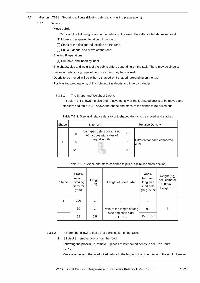
7.3.1.1. The Shape and Weight of Debris
Table 7-3-1 shows the size and relative density of the L-shaped debris to be moved and
stacked; and table 7-3-2 shows the shape and mass of the debris to be pulled out.
Table 7-3-1: Size and relative density of L-shaped debris to be moved and stacked
Shape Size (cm) Relative Density
L
50
25
12.5
L-shaped debris comprising
of 4 cubes with sides of
equal length.
1.5
1
0.5
Different for each connected
cube.
Table 7-3-2: Shape and mass of debris to pull out (circular cross-section)
Shape
Cross-
section
(circular)
diameter
(mm)
Length
(m) Length of Short Side
Angle
between
long and
short side
(Degree °)
Weight (Kg)
per Diameter
100mm・
Length 1m
I 100
50
25
2
1
0.5
- -
4 L Ratio of the length of long
side and short side
1:1 ~ 4:1
90
J 15 〜 60
7.3.1.2. Perform the following tasks or a combination of the tasks.
(1) 【TS2-A】Remove debris from the road.
Following the procedure, remove 2 pieces of interlocked debris to secure a route.
Ex. 1)
Move one piece of the interlocked debris to the left, and the other piece to the right. However,
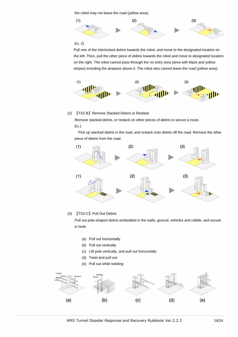
WRS Tunnel Disaster Response and Recovery Rulebook Ver.2.2.3 16/24
the robot may not leave the road (yellow area).
Ex. 2)
Pull one of the interlocked debris towards the robot, and move to the designated location on
the left. Then, pull the other piece of debris towards the robot and move to designated location
on the right. The robot cannot pass through the no entry area (area with black and yellow
stripes) including the airspace above it. The robot also cannot leave the road (yellow area).
(2) 【TS2-B】Remove Stacked Debris or Restack
Remove stacked debris, or restack on other pieces of debris to secure a route.
Ex.)
Pick up stacked debris in the road, and restack onto debris off the road. Remove the other
piece of debris from the road.
(3) 【TS2-C】Pull Out Debris
Pull out pole-shaped debris embedded in the walls, ground, vehicles and rubble, and secure
a route.
(a) Pull out horizontally
(b) Pull out vertically
(c) Lift pole vertically, and pull out horizontally
(d) Twist and pull out
(e) Pull out while twisting
WRS Tunnel Disaster Response and Recovery Rulebook Ver.2.2.3 17/24
(4) 【TS2-D】Blasting Preparations
Using tools, drill a hole in the debris and insert a cylinder into the hole.
○ Grasp the tool.
■ The tool is a concrete boring drill with a mass of 30kg.
○ Drill a hole 50~100mm in diameter, and 300~500mm deep in the debris.
■ Press the tip of the drill with a force of 300N perpendicular to the drilling
point, and hold for a specified amount of time. The reactionary force from
the drilling will be felt by the robot through the tool.
■ The margin for error in coordinates is ±30mm for position and ±5° for angle.
※ Changes may be made to the diameter and depth of the hole.
○ Insert a cylinder into the hole.
■ The diameter of the cylinder is 25~50mm, 50% of the hole’s diameter, the
length is 200~300mm, and it weighs 0.1~0.75 kg.
※ Changes may be made to the cylinder’s diameter etc.
7.3.2. Score and Penalties
7.3.2.1. Task Score
【TS2-A】
・Remove debris from road: 6 points, 3 locations
【TS2-B】
・Restack: 12 points, 1 location
【TS2-C】
・Pull out debris: 14 points, 2 locations
【TS2-D】
・Drill hole: 14 points, 2 locations
・Insert cylinder: 14 points, 2 locations
※ Each of the numbers of debris and number of points may change.
7.3.2.2. Bonus Score (Time: May only be gained if tasks【T2S-A】【T2S-B】【T2S-C】【T2S-D】
are all completed)
・Added according to 6.3.4.
7.3.2.3. Bonus Score (Environment)
・0~15 points depending on quality of information from the entire competition field.
7.3.2.4. Bonus Score (Task)
・Bonus score coefficient 0.5~2.0
7.3.2.5. Penalties
・None.
7.4. Mission【TS3】: Extinguish a Fire
7.4.1. Details
Using the fire extinguisher in the tunnel, extinguish a fire that has broken out in the tunnel.
7.4.1.1. Figure 7-7-1 shows the outward appearance of the fire extinguisher.
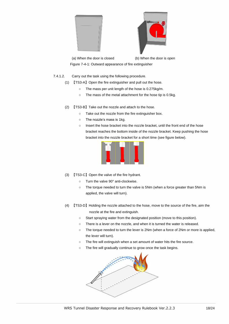
WRS Tunnel Disaster Response and Recovery Rulebook Ver.2.2.3 18/24
(a) When the door is closed (b) When the door is open
Figure 7-4-1: Outward appearance of fire extinguisher
7.4.1.2. Carry out the task using the following procedure.
(1) 【TS3-A】Open the fire extinguisher and pull out the hose.
○ The mass per unit length of the hose is 0.275kg/m.
○ The mass of the metal attachment for the hose tip is 0.5kg.
(2) 【TS3-B】Take out the nozzle and attach to the hose.
○ Take out the nozzle from the fire extinguisher box.
○ The nozzle’s mass is 1kg.
○ Insert the hose bracket into the nozzle bracket, until the front end of the hose
bracket reaches the bottom inside of the nozzle bracket. Keep pushing the hose
bracket into the nozzle bracket for a short time (see figure below).
(3) 【TS3-C】Open the valve of the fire hydrant.
○ Turn the valve 90° anti-clockwise.
○ The torque needed to turn the valve is 5Nm (when a force greater than 5Nm is
applied, the valve will turn).
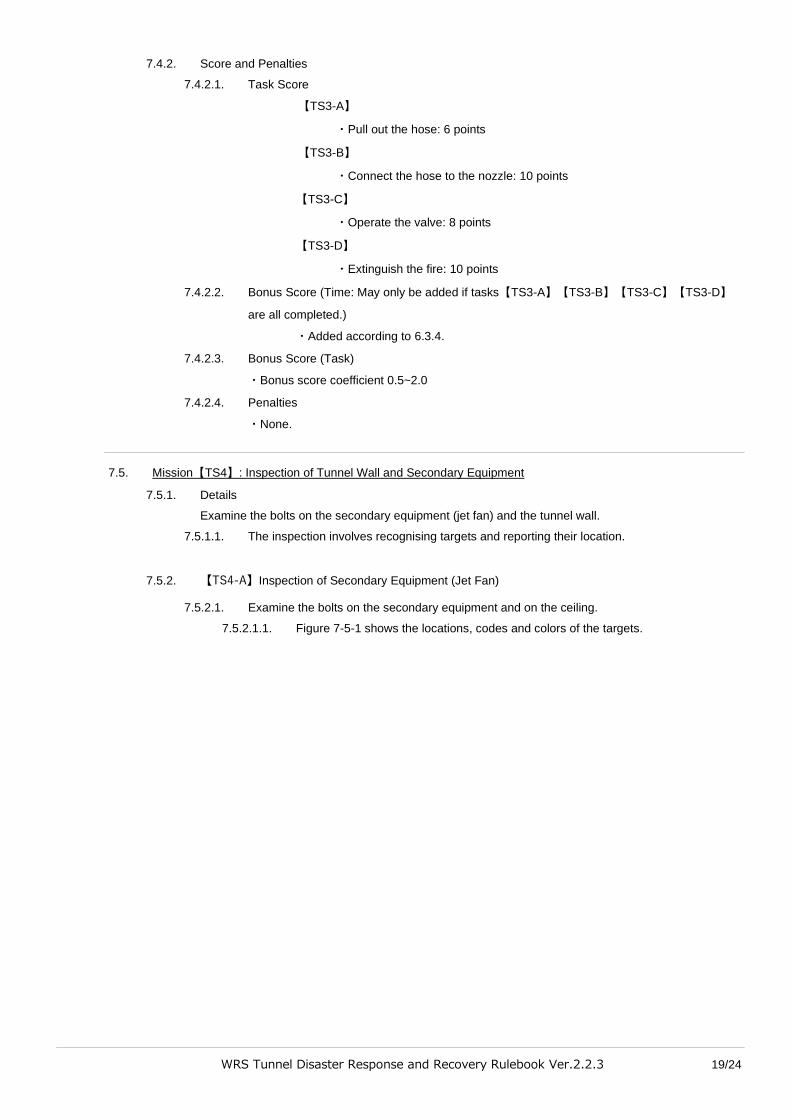
(4) 【TS3-D】Holding the nozzle attached to the hose, move to the source of the fire, aim the
nozzle at the fire and extinguish.
○ Start spraying water from the designated position (move to this position).
○ There is a lever on the nozzle, and when it is turned the water is released.
○ The torque needed to turn the lever is 2Nm (when a force of 2Nm or more is applied,
the lever will turn).
○ The fire will extinguish when a set amount of water hits the fire source.
○ The fire will gradually continue to grow once the task begins.
WRS Tunnel Disaster Response and Recovery Rulebook Ver.2.2.3 19/24
7.4.2. Score and Penalties
7.4.2.1. Task Score
【TS3-A】
・Pull out the hose: 6 points
【TS3-B】
・Connect the hose to the nozzle: 10 points
【TS3-C】
・Operate the valve: 8 points
【TS3-D】
・Extinguish the fire: 10 points
7.4.2.2. Bonus Score (Time: May only be added if tasks【TS3-A】【TS3-B】【TS3-C】【TS3-D】
are all completed.)
・Added according to 6.3.4.
7.4.2.3. Bonus Score (Task)
・Bonus score coefficient 0.5~2.0
7.4.2.4. Penalties
・None.
7.5. Mission【TS4】: Inspection of Tunnel Wall and Secondary Equipment
7.5.1. Details
Examine the bolts on the secondary equipment (jet fan) and the tunnel wall.
7.5.1.1. The inspection involves recognising targets and reporting their location.
7.5.2. 【TS4-A】Inspection of Secondary Equipment (Jet Fan)
7.5.2.1. Examine the bolts on the secondary equipment and on the ceiling.
7.5.2.1.1. Figure 7-5-1 shows the locations, codes and colors of the targets.

WRS Tunnel Disaster Response and Recovery Rulebook Ver.2.2.3 20/24
Figure 7-5-1:Target locations, codes and colors
7.5.3. 【TS4-B】Inspection of the Tunnel Wall
7.5.3.1. Examine the targets on the tunnel wall.
7.5.3.1.1. The targets are in positions shown in figure 7-5-2.
Figure 7-5-2: Positions of Targets on Tunnel Wall
7.5.4. Score and Penalties
7.5.4.1. Task Score
【TS4-A】Equipment Recognise the targets: 5 points, 4 locations
【TS4-B】Wall Recognise the targets: 5 points, 4 locations
7.5.4.2. Bonus Score (Time: Only added if all targets are recognized and answered correctly.)
・ Added according to 6.3.4.

WRS Tunnel Disaster Response and Recovery Rulebook Ver.2.2.3 21/24
7.5.4.3. Bonus Score (Environment)
・None
7.5.4.4. Penalties
・None
7.5.4.5. Bonus Score (Task)
・Bonus score coefficient 0.5~2.0
8. Type of Road Surface
The road surface uses a combination of the following:
・Level Surface
There may be a gradient
・Crossing Ramp
For S, M size robots
・Elevated Ramp
For S, M size robots
・Narrow Spaces
For all sizes of robot
・Rough Terrain (Chocolate and waffle)
For L size robots
・Capsule
8.1. Types of Road Surface
8.1.1. Details of Obstacles (Type and Shape)
8.1.1.1. Crossing Ramp【S, M size robots】
Obstacles in alternating slopes with a 15° incline.
8.1.1.2. Elevated Ramp【S, M size robots】
Obstacles consisting of a combination of different height slopes with a 15° incline.
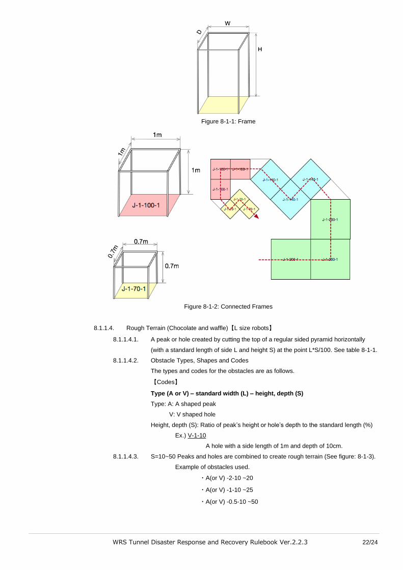
8.1.1.3. Confined Spaces (jungle gym)【All sizes of robot】
8.1.1.3.1. Move within connected cube-shaped frames. (See Figure 7-3-1, Figure 7-3-2)
8.1.1.3.2. Types, shapes and codes for obstacles
【Codes】
Type (J) – Standard Width (U) - Scale (S) – Height (h)
Type: J
Standard Width (U): Standard width of cube-shaped frame. Unit in m.
Scale (S): Scale of frame width. Percentage of standard width to frame (%).
Height (h): Frame height. Proportionate to the frame width W (=U×S).
Ex.) J-1-100-1
Frame with 1 side of base length W=1m, height H=1
Ex.) J-1-70-1.5
Frame with 1 side of base length W=70cm, Height H=1.05m
WRS Tunnel Disaster Response and Recovery Rulebook Ver.2.2.3 22/24
Figure 8-1-1: Frame
Figure 8-1-2: Connected Frames
8.1.1.4. Rough Terrain (Chocolate and waffle)【L size robots】
8.1.1.4.1. A peak or hole created by cutting the top of a regular sided pyramid horizontally
(with a standard length of side L and height S) at the point L*S/100. See table 8-1-1.
8.1.1.4.2. Obstacle Types, Shapes and Codes
The types and codes for the obstacles are as follows.
【Codes】
Type (A or V) – standard width (L) – height, depth (S)
Type: A: A shaped peak
V: V shaped hole
Height, depth (S): Ratio of peak’s height or hole’s depth to the standard length (%)
Ex.) V-1-10
A hole with a side length of 1m and depth of 10cm.
8.1.1.4.3. S=10~50 Peaks and holes are combined to create rough terrain (See figure: 8-1-3).
Example of obstacles used.
・A(or V) -2-10 ~20
・A(or V) -1-10 ~25
・A(or V) -0.5-10 ~50

WRS Tunnel Disaster Response and Recovery Rulebook Ver.2.2.3 23/24
Table 8-1-1: Rough terrain (chocolate and waffle)
L=1m S = 100 S = 10
A
A-1-100
A-1-10
V
Figure 8-1-3: Examples of combinations to create rough terrain
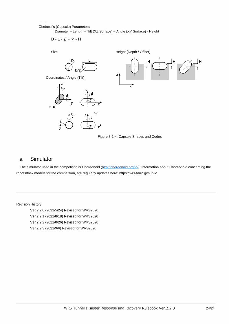
8.1.1.5. Capsule
8.1.1.5.1. Capsules partially exposed on the road surface.
8.1.1.5.2. Obstacle Types, Shapes and Codes
The types and shapes of obstacle are as follows.
【Codes】
Diameter - Length – Tilt (XZ surface) – Angle (XY surface) - Height
WRS Tunnel Disaster Response and Recovery Rulebook Ver.2.2.3 24/24
Figure 8-1-4: Capsule Shapes and Codes
9. Simulator
The simulator used in the competition is Choreonoid (http://choreonoid.org/ja/). Information about Choreonoid concerning the
robots/task models for the competition, are regularly updates here: https://wrs-tdrrc.github.io
Revision History
Ver.2.2.0 (2021/5/24) Revised for WRS2020
Ver.2.2.1 (2021/8/18) Revised for WRS2020
Ver.2.2.2 (2021/8/26) Revised for WRS2020
Ver.2.2.3 (2021/9/6) Revised for WRS2020
Obstacle’s (Capsule) Parameters
Diameter – Length – Tilt (XZ Surface) – Angle (XY Surface) - Height
Size Height (Depth / Offset)
Coordinates / Angle (Tilt)