detailed specifications - central power research institute detailed specifications distribution...
TRANSCRIPT

DATB Specifications
Page 1 of 35 CPRI
Detailed Specifications
Distribution Automation Test Bed (DATB)
“This Tender Document shall be used only for
the purpose of responding to this tender and
cannot be used for any other purpose without
written consent from CPRI.”
DATB Specifications
Page 2 of 35 CPRI
25 S
ept
201
7
Contents 1 Introduction .......................................................................................................................................... 5
2 Abbreviations ........................................................................................................................................ 5
3 Intended uses for the DATB .................................................................................................................. 6
3.1 Exercise the DATB Use Cases ........................................................................................................ 6
3.2 Demonstrate and Verify Distribution Automation functions ....................................................... 6
3.3 Interoperability Testing ................................................................................................................. 7
3.3.1 CIM Compliance of DA Controls per IEC 61968 .................................................................... 7
3.4 Parts of the Distribution Automation Test Bed ............................................................................ 8
3.4.1 A Generic Integration Model ................................................................................................ 8
3.4.2 Small scale transient simulation ........................................................................................... 8
3.4.3 Larger scale distribution simulation ...................................................................................... 8
3.4.4 Integration with the SituTB SCADA/ADMS system ............................................................... 8
3.4.5 Integration with the 11kV transformer pad .......................................................................... 8
3.4.6 Integration with the substations ........................................................................................... 8
3.4.7 Analysis tools ......................................................................................................................... 8
4 DATB Components ................................................................................................................................ 9
4.1 General Requirements for Substation Equipment ........................................................................ 9
4.2 Small Scale Simulation ................................................................................................................ 11
4.2.1 Small Scale Simulator specification: .................................................................................... 11
4.2.2 Interface from Simulator to SCADA/ADMS ......................................................................... 11
4.3 Large Scale Simulation ................................................................................................................ 12
4.3.1 Required for Large Scale Simulation ................................................................................... 12
4.3.2 Integration with SituTB SCADA/ADMS ................................................................................ 12
4.4 Integration with SGTB 11kV transformer pad physical switchgear ............................................ 13
4.4.1 Recommended 11kV equipment for the Transformer Pad (11kV Line Hardware) (supply of
these items are not in the scope of this tender; however information is provided for ease of
integration with these devices; the selected bidder shall support for integration with these items;
these items will be procured through separate tender or CPRI will arrange these items) ................. 13
4.5 Generic Integration Model .......................................................................................................... 15
4.5.1 Uninterruptible Power Supply ............................................................................................ 16
4.6 Analysis tools............................................................................................................................... 16

DATB Specifications
Page 3 of 35 CPRI
25 S
ept
201
7
4.6.1 SCADA Simulator ................................................................................................................. 16
4.6.2 Station Level Computer....................................................................................................... 17
4.6.3 Gateway .............................................................................................................................. 17
4.6.4 Time Reference (supply scope covered under Situational Awareness test bed part of this
tender) 18
4.6.5 Power Supply ...................................................................................................................... 18
4.6.6 LAN Ethernet Switch ........................................................................................................... 18
4.6.7 Portable Notebook Computers (2 recommended): ............................................................ 19
4.6.8 Router ................................................................................................................................. 19
4.7 Miscellaneous and Spare Parts ................................................................................................... 20
5 RTU Specification ................................................................................................................................ 20
5.1.1 Data Acquisition .................................................................................................................. 20
5.1.2 Estimating RTU Point Count ................................................................................................ 23
5.1.3 RTU Architecture ................................................................................................................. 23
5.1.4 Power Supply ...................................................................................................................... 26
5.1.5 Local Control Panel ............................................................................................................. 27
5.1.6 RTU Software ...................................................................................................................... 28
5.1.7 Enclosures ........................................................................................................................... 29
6 Physical Structure (Rack)r ................................................................................................................... 30
7 Communication Network .................................................................................................................... 31
7.1 Network Performance Requirements ......................................................................................... 31
7.2 Connection from DATB to the SGTB external transformer pad .................................................. 31
7.2.1 Fiber Link Specification ....................................................................................................... 32
7.3 SNMP Manager ........................................................................................................................... 32
7.4 Redundancy Requirements ......................................................................................................... 32
7.5 Cyber Security Requirements for Distribution Automation ....................................................... 32
8 Reliability and Availability vs. Flexibility .............................................................................................. 33
9 Contracting Options ............................................................................................................................ 33
10 Feature Quantities: ............................................................................................................................. 34
11 Mapping Functions to Features (only for information) ....................................................................... 34
DATB Specifications
Page 4 of 35 CPRI
25 S
ept
201
7
Figures Figure 3-1 Interoperability Context-Setting Framework, aka GWAC Stack .................................................. 7
Figure 4-1: DATB Components .................................................................................................................... 10
Figure 4-2 11kV Equipment on SGTB Transformer Pad ............................................................................. 14
Figure 4-3 Communications using VPN across the SituTB, DATB, and SASTB over the CPRI network and
cellular connections. ................................................................................................................................... 16
Figure 6-1 Rack mounts for DATB Equipment ............................................................................................ 31
Tables
Table 2-1 Abbreviations ................................................................................................................................ 6
Table 10-1 DATB Features List .................................................................................................................... 34
Table 11-1 Selection options for each Feature ........................................................................................... 34
Table 11-2 Function dependency on Features ........................................................................................... 35

DATB Specifications
Page 5 of 35 CPRI
25 S
ept
201
7
1 Introduction The Distribution Automation Test Bed (DATB) consists of all equipment, devices, and software
associated with information flow within the test bed. In this respect, the DATB includes
Small scale transient simulation of a section of the power grid using one or more Relay Test Sets
for the simulation of distribution faults and automation actions.
Integration with the CPRI Power Systems Laboratory RTDS and Opal-RT simulators for larger and
more complex simulations
Integration with the Situational Awareness Test Bed SCADA/ADMS system.
Integration of distribution hardware installed on the SGTB transformer pad for visual
demonstration of automated and remote control of feeder switchgear.
Instrumentation used to test and verify conformance of DA devices to relevant standards.
Devices and fixtures needed to realize the integration of DATB with physical signals, including
o Networking equipment
o Remote Terminal Units
o Smart power meters
o Intelligent field device controls such as recloser, load break switch, and Communicating
Fault Passing Indicator interface controls.
This document provides the DATB specification. Conceptual Logical and Physical architectures of the
Distribution Automation System are suggested.
2 Abbreviations
Term Meaning
CCTB Communications and Computing Test Bed
DATB Distribution Automation Test Bed
DERTB Distributed Energy Resources Test Bed
EVTB Garage of the Future Test Bed
HANTB Home Area Network Test Bed
HSR High-availability Seamless Redundancy (IEC 62439-3 clause 5)
MOAB Motor operated air breaker
PRP Parallel Redundancy Protocol (IEC 62439-3 clause 4)

DATB Specifications
Page 6 of 35 CPRI
25 S
ept
201
7
Term Meaning
PSTB Power System Test Bed
SASTB Substation Automation System Test Bed
SituTB Situational Awareness Test Bed
SNMP Simple Network Maintenance Protocol
SNTP Simple Network Time Protocol
Table 2-1 Abbreviations
3 Intended uses for the DATB
3.1 Exercise the DATB Use Cases
Per the Conceptual Design Report (SGTB Task 5) the DATB will support the following use cases:
6 - Distribution Automation Test Bed Use Cases
6.1 FLISR & FDI
6.2 Volt-VAR Control
6.3 Reconfiguration of the circuit on overloading scenario.
6.4 Load shedding
6.5 CIM compliance for DMS as per IEC 61968
Demo field device operation on the SGTB Transformer Pad
Observe 220kV and 33kV substation operation
3.2 Demonstrate and Verify Distribution Automation functions
The DATB will be used to stage simulated interconnecting distribution feeders to observe grid behaviour
under load, fault and overload conditions. An overlay of RTU and physical distribution automation
controls will interact with the simulations, allowing the analysis of the effectiveness of the automation
scheme, the expected time span required for operation and reduction of outage time due to DA
operation, improvement in Key Performance Indicators (SAIDI, SAIFI, CAIDI, etc. computed by the SituTB
SCADA/ADMS), and the quality of the information available to distribution system operators and field
service technicians. SGTB will demonstrate the remote operation of field devices by operating the
switchgear installed on the SGTB transformer pad just outside the building.
DATB will install Router, RTU, and selected equipment in the 33kV on campus and 220kV off campus
substations for observation of the operation of the real power grid.
DATB Specifications
Page 7 of 35 CPRI
25 S
ept
201
7
Demonstration of these techniques will be of value to CPRI associates interested in employing the
methods on their own distribution grids, and in educational opportunities for utility and academic
associates.
3.3 Interoperability Testing
In addition to conformance testing of the above standards, DATB will be used to verify Interoperability
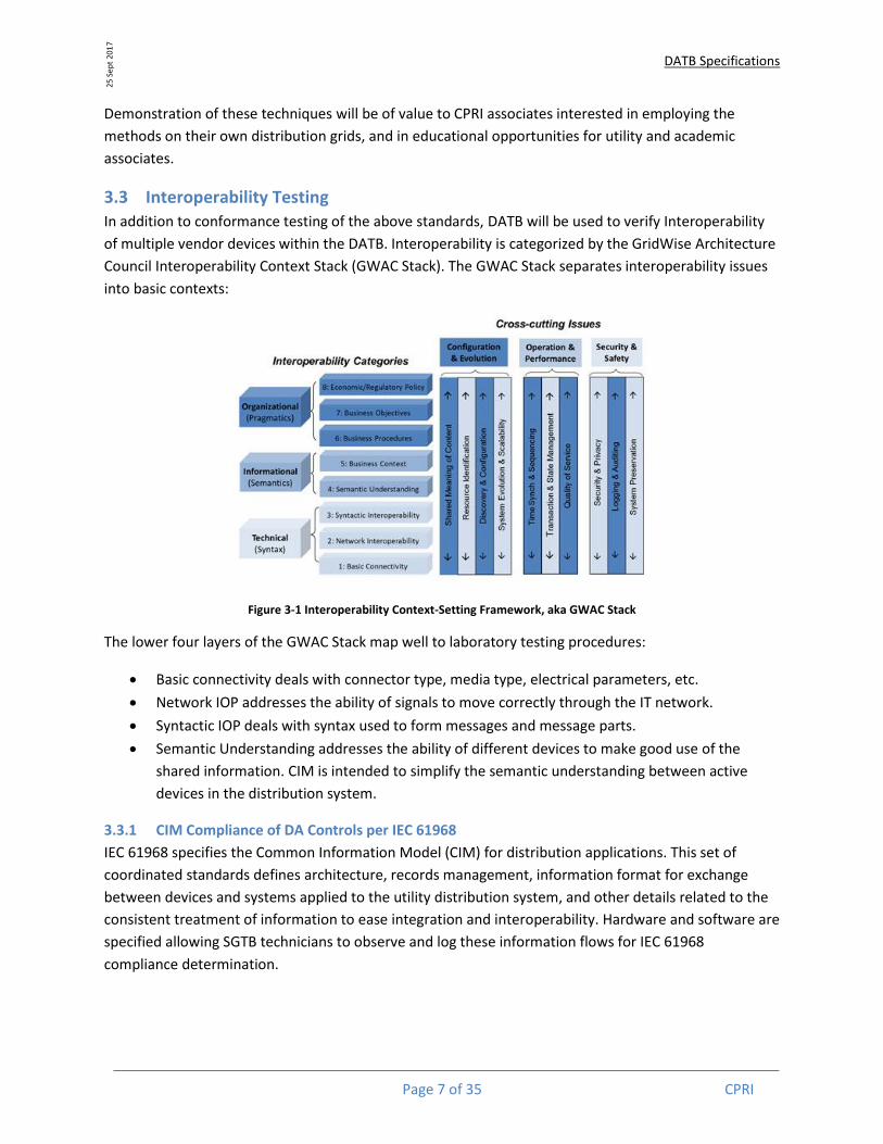
of multiple vendor devices within the DATB. Interoperability is categorized by the GridWise Architecture
Council Interoperability Context Stack (GWAC Stack). The GWAC Stack separates interoperability issues
into basic contexts:
Figure 3-1 Interoperability Context-Setting Framework, aka GWAC Stack
The lower four layers of the GWAC Stack map well to laboratory testing procedures:
Basic connectivity deals with connector type, media type, electrical parameters, etc.
Network IOP addresses the ability of signals to move correctly through the IT network.
Syntactic IOP deals with syntax used to form messages and message parts.
Semantic Understanding addresses the ability of different devices to make good use of the
shared information. CIM is intended to simplify the semantic understanding between active
devices in the distribution system.
3.3.1 CIM Compliance of DA Controls per IEC 61968
IEC 61968 specifies the Common Information Model (CIM) for distribution applications. This set of
coordinated standards defines architecture, records management, information format for exchange
between devices and systems applied to the utility distribution system, and other details related to the
consistent treatment of information to ease integration and interoperability. Hardware and software are
specified allowing SGTB technicians to observe and log these information flows for IEC 61968
compliance determination.
DATB Specifications
Page 8 of 35 CPRI
25 S
ept
201
7
Interoperability Testing requires the staging of devices, systems, and software from different vendors
and verifying that these devices interoperate in reliable and predictable ways. The DATB will provide the
structures and fixtures to facilitate this type of testing.
3.4 Parts of the Distribution Automation Test Bed
The DATB consists of the following parts:
3.4.1 A Generic Integration Model
Used for integrating CPRI facilities and laboratories into the DATB.
3.4.2 Small scale transient simulation
Simulation of interconnected distribution feeders interfaced to the Situational Awareness Test Bed
SCADA/ADMS system. This small scale simulator is realized by a relay test set with sufficient analog
outputs and digital simulation of up to 20 distribution buses with feeder loads, front-ended with the
Generic Integration Model.
3.4.3 Larger scale distribution simulation
Simulation of more complex distribution feeder configurations. This larger scale simulation is realized by
integration of the DATB and SituTB with the existing CPRI Power Systems Lab RTDS and Opal-RT
simulators, physical distribution field controls, Hardware in Loop testing, using the Generic Integration
Model and the CPRI IP network.
3.4.4 Integration with the SituTB SCADA/ADMS system
Integration with SituTB using the CPRI network and the Generic Integration Model Router and RTU.
3.4.5 Integration with the 11kV transformer pad
Integration with physical switchgear devices located on the SGTB building transformer pad for
demonstration and verification of the operation of field devices by automated control and distribution
operator command, using a 12-strand fiber optic network link, GIM Router/VPN, RTU, and other field
controls.
3.4.6 Integration with the substations
Integrate the remote 220kV substation using the router cell modem and the local 33kV substation using
the router on the CPRI campus network. Modernization hardware in both substations is assumed from
another project.
3.4.7 Analysis tools
Hardware and software ools for the capture and analysis of information flows throughout the DATB
between field components, field to station, and field to distribution control center.
DATB will interact with the Situational Awareness Test Bed (SituTB), the Substation Automation Test Bed
(SASTB), and the CPRI Power Systems Lab for evaluation of automation system performance in selected
testing scenarios. Other on and off campus locations may be added using the Generic Integration Model.
DATB Specifications
Page 9 of 35 CPRI
25 S
ept
201
7
4 DATB Components DATB shall be configured as indicated in figure 4-1. Integration of the several components of the DATB
shall be based on the existing CPRI backbone TCP/IP network with VPN-enabled Routers and RTUs.
4.1 General Requirements for Substation Equipment
Station Level IEDs shall provide at least (2) Ethernet ports for redundant connection to the Dual Station
LAN and for support of PRP and HSR.
Station Level IEDs shall support IEC 61850 and other international standards, particularly:
61850-3 General requirements (electrical and environmental stresses)
61850-8-1 Publish and subscribe to GOOSE messaging by Ethernet Multicast
61850-9-2 Subscribe to Sampled Value Streaming by Ethernet Multicast
61850-9-3 Time synch per IEEE-1588
61850-90-1 Inter-substation GOOSE messaging publication and subscription
61850-90-2 Station to control center GOOSE messaging publication and subscription
61850-90-5 Routing of GOOSE messages, SV streams, and synchrophasor streams outside of
the Local Area Network
62351 Support for Device Level Security including user authentication, multiple user
roles, user role based functional authorization, and protected firmware revision
62439-3 support for HSR network loops and PRP on dual station and process LAN

DATB Specifications
Page 10 of 35 CPRI
25 S
ept
201
7
Figure 4-1: DATB Components
DATB
Generic Integration Model to Power System Lab
Transformer Pad using fiber link
SituTB
Small Scale Simulation
Small SCADA/ADMS Display (2x2)
SCADA/ADMS
Display Control
OperatorOperator
Large Scale Simulation
IED
FPI
Recloser
RMU
LBS
RTU
CPRI Campus Network
Analysis ToolsAnalysis Tools
Routerw/Gateway
VPNIEC-104
RouterVPN
RouterVPN
RouterVPN
Fiber LinkIEC-104
Wireless Link
RTU IEC-104
IED
RTUIEC-104

DATB Specifications
Page 11 of 35 CPRI
25 S
ept
201
7
4.2 Small Scale Simulation
Small Scale Simulation components shall be under complete control of the DATB staff. The simulator
shall execute on Relay Test Set hardware with transient simulation capability.
Distribution control equipment can be exercised using Relay Test Sets. The addition of simulation
software to the test set permits more complex circuit interactions to be analysed. For example, an
ADMS FLISR test would start with a simulation model of a circuit with protection circuit breaker and
remotely controllable feeder switchgear. With switchgear controllers in the simulation loop, ADMS can
issue commands through a SCADA IEC 60870-5-104 interface to locate the fault, isolate the faulted
section, and restore service to the maximum number of customers.
Signal Generation requirements depend on the extent of excitation of the controls required for the
desired set of tests. (6) current and (4) voltage analog outputs can excite IEDs, metering, and field
control devices such as Recloser, Load Break Switch, and Voltage Regulator controls. Additional
synchronized analog or sampled value (merging units modelled in a simulator and injected into an IED
through a local area Ethernet network) can expose more complex interactions.
4.2.1 Small Scale Simulator specification:
Signal Generator Programmable by connected Windows laptop computer
Hardware In Loop capability
COMTRADE playback
Test scripting
Time synchronization per 61850-9-3 (IEEE 1588 PTP)
(6) current channels with 32 amp capacity, error <1%
(4) voltage channels with 300 VAC phase-ground, error<1%
(10) digital input
(4) digital output relay 300 VAC 8 amp
(4) open collector transistorized output
(10) analog input 300 VAC, minimum sample rate 80 samples/cycle, overload protection
Transient triggering at configured threshold voltage
Programmable simulation of 20 or more buses
o Simulation of 50 or 60 Hz power system signals
o Simulation of (3) 4-channel voltage and 4-channel current Merging Units to Ethernet per
61850-90-2LE Sampled Values
o Sampled Value streams on (2) Ethernet ports to dual Process Bus LAN
o Generation of (>=32) 61850 GOOSE event messages from simulation
o Subscription to (>=32) 61850 GOOSE messages from Device Under Test
4.2.2 Interface from Simulator to SCADA/ADMS
Simulator output shall be fed to different electronic devices, which in turn will be interfaced to the
SCADA/ADMS system in the SituTB using IEC 60870-5-104 (or IEC-104) protocol. Distribution system
conditions read by SCADA polls are available to ADMS; ADMS functions issue commands that are passed
DATB Specifications
Page 12 of 35 CPRI
25 S
ept
201
7
through SCADA to the distribution automation equipment; the DA equipment feed into the simulator to
alter the simulation results.
Interface devices include
IEC-104 RTU per the section 5 RTU specification
IEC-104 Power meter or IED that can be polled directly by SCADA
IEC-103 Power meters and IEDs with a -104 to -103 Gateway
61850 IEDs per SASTB specification with IEC-104 to 61850 Gateway
IEC 60870-5 Field Controllers for DA hardware with Gateway as needed
This minimum configuration will allow the transient simulation of simpler distribution feeder
configurations with smart field control hardware elements in the control loop of the simulator. The
exercise of the Distribution Automation equipment coupled with protocol analysis tools will allow the
capture and analysis of information exchanges, enabling the technician to evaluate conformance of the
device under test to standards, including IEC-104 SCADA protocol and IEC 61968 information modelling.
4.3 Large Scale Simulation CPRI has an on-campus Power Systems Laboratory with extended simulation capability. An existing mid-
scale RTDS system, and a new large-scale Opal-RT system, are not under full control of SGTB staff, but
are available for SGTB use on a scheduled basis. However, the Power System Laboratory is in another
building on the CPRI Bangalore campus.
CPRI has an existing high-speed IP network that extends throughout the campus. This network will be
used for the IEC 60870-5-104 SCADA operation. By locating SCADA-compatible hardware in a Hardware-
in-the-Loop (HIL) configuration on the Power System Laboratory simulators, SCADA/ADMS is able to
reach out to the Power System Lab to remotely execute ADMS operations.
Access to the Power Systems Lab over the CPRI network shall be through the application of the GIM
Routers configured to create a Virtual Private Network (VPN) between the SituTB and the Power
Systems Lab. The smart digital controls used in DA testing in the Small Scale Simulation may be moved
to the Power System Lab and connected to SCADA/ADMS by VPN over the campus network.
4.3.1 Required for Large Scale Simulation
Power System Lab simulators must have distribution equipment modeling capabilities. If not
existing already, buy those components from the simulator supplier (RTDS or Opal-RT).
CPRI backbone IP network for communication from SGTB to Power Systems Lab.
Generic Integration Model Router and
60870-5-104 SCADA compatible field devices as specified in section 4.1.2.
4.3.2 Integration with SituTB SCADA/ADMS
SituTB SCADA system will employ IEC 60870-5-104 SCADA protocol. This protocol is compatible with
network communication and will be connected to the CPRI campus IP network. Locating IEC-60870-5-
104 compatible devices at the Power Systems Lab will allow SCADA to poll a simulation of distribution

DATB Specifications
Page 13 of 35 CPRI
25 S
ept
201
7
circuits to enable ADMS functions such as FLISR and Volt-VAR Control. Integration with the IEC 60870-5-
104 SCADA system may require the use of a Gateway device as an intermediary between -104 and the
IED protocol (IEC 60870-5-103 or IEC 61850).
On occasion the interface will support Distributed Energy Resources modelled on the simulator. In such
cases, the Gateway will support the transition from IEC 60870-5-104 to the protocol supported by the
DER device.
4.4 Integration with SGTB 11kV transformer pad physical switchgear
11kV switchgear located outside the SGTB building on the SGTB building power transformer pad will be
accessed by installing an RTU on the pad. Additional equipment such as power meter, power quality
meter, revenue meter, and 61850 merging unit may also be located in that enclosure and interfaced to
potential and current transformers on the low voltage side of the pad mount transformer to observe
building load. The transformer pad equipment shall be mounted in a weather tight enclosure of
sufficient size to avoid crowding or overheating of the equipment, with power and control signal cabling
to the pad switchgear, and twelve-strand fiber optic network cabling back to the SGTB building DATB
space (see section 6.2). The transformer pad RTU is as specified in section 5 below.
4.4.1 Recommended 11kV equipment for the Transformer Pad (11kV Line Hardware) (supply of
these items are not in the scope of this tender; however information is provided for ease of
integration with these devices; the selected bidder shall support for integration with these
items; these items will be procured through separate tender or CPRI will arrange these items)
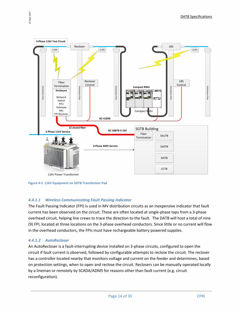
CPRI desires the installation of 11kV switchgear on the transformer pad just outside the SituTB space.
This equipment shall be positioned such that the status indications of the devices are visible from the
South West window of the SituTB area (room 13), and shall be cabled into the SCADA/ADMS system so
that the switchgear can be operated both by operator command and on certain ADMS functions (e.g.
opening a physical device in the process of managing a simulated distribution automation operation).
The equipment is to include (see Figure 4.2)
(9) 11kV overhead mounted Wireless Communicating Fault Passing Indicators
(1) 11kV pole mounter overhead 3-phase Recloser and auto-reclose controller
(1) 11kV 3-position 3-phase Compact Ring Main Unit with internal RTU and power meters
(1) 11kV Sectionalizer realized as a 3-phase Load Break Switch with LBS controller
(5) 11kV overhead distribution poles with crossarms, brackets, insulators, riser cabling,
overhead conductors, and all required hardware to mount the above equipment.
DATB Specifications
Page 14 of 35 CPRI
25 S
ept
201
7
Figure 4-2 11kV Equipment on SGTB Transformer Pad
4.4.1.1 Wireless Communicating Fault Passing Indicator
The Fault Passing Indicator (FPI) is used in MV distribution circuits as an inexpensive indicator that fault
current has been observed on the circuit. These are often located at single-phase taps from a 3-phase
overhead circuit, helping line crews to trace the direction to the fault. The DATB will host a total of nine
(9) FPI, located at three locations on the 3-phase overhead conductors. Since little or no current will flow
in the overhead conductors, the FPIs must have rechargeable battery powered supplies.
4.4.1.2 AutoRecloser
An AutoRecloser is a fault-interrupting device installed on 3-phase circuits, configured to open the
circuit if fault current is observed, followed by configurable attempts to reclose the circuit. The recloser
has a controller located nearby that monitors voltage and current on the feeder and determines, based
on protection settings, when to open and reclose the circuit. Reclosers can be manually operated locally
by a lineman or remotely by SCADA/ADMS for reasons other than fault current (e.g. circuit
reconfiguration).
11kV Power Transformer
Compact RMU
LBSRecloser3 FPI 3 FPI 3 FPI
Recloser Control
LBS Control
Enclosure
NetworkSwitch
RTUGateway
MUFPI Receiver
3-Phase 11kV Test Circuit
3-Phase 11kV ServiceSGTB Building
3-Phase 440V Service
12 strand fiber
IEC 61850
Fiber Termination
SituTB
SASTB
DATB
CCTB
Compact RMU
Distrib
utio
n P
ole
Distrib
utio
n P
ole
Distrib
utio
n P
ole
Distrib
utio
n P
ole
Distrib
utio
n P
ole
Fiber Termination
IEC 60870-5-104

DATB Specifications
Page 15 of 35 CPRI
25 S
ept
201
7
4.4.1.3 Ring Main Unit
A Ring Main Unit (RMU) is a switching device that allows the utility to remotely or locally connect and
disconnect multiple circuits from a small section of bus. The RMU can act as a tap point for a distribution
transformer, a sectionalizing switch, or a distribution automation element for reconfiguring a circuit.
An automated (motor driven with remote control) 3-position Ring Main Unit (RMU) shall be located on
the transformer pad such that a viewer from the SGTB building can see the front panel indications of
switch state when the cabinet doors are open. The RMU positions shall be individually observable and
controllable by commands issued through the SituTB SCADA/ADMS system.
4.4.1.4 Sectionalizer
A Sectionalizer is a switching element that allows a circuit to be opened, isolating the downstream
section of the circuit from the upstream section. Sectionalizing may be accomplished with a load break
switch (LBS) when normal load current is flowing, or may only be able to operate on a de-energized
circuit with no current flow at the time of opening. Sectionalizers often include automation to open the
switch in case of a loss of voltage due to the opening of an upstream circuit breaker, thus isolating any
downstream fault an allowing the circuit breaker to be closed.
The Sectionalizer to be installed on the SGTB Transformer Pad shall include a communication controller
allowing local or remote operation by SCADA/ADMS, and shall automatically open upon a loss of voltage
resulting from operation of the upstream Recloser or RMU.
4.5 Generic Integration Model
CPRI is home to a large number of test laboratories dedicated to specialization in particular areas of
power system engineering. The Generic Integration Model (GIM) is a model for a simple, repeatable
interface from DATB and SituTB on the campus network to other labs around the campus. The Generic
Integration Model uses the campus network for communications when available, placing integrating
components at remote locations for short or long term observation and/or control of other test
environments. Communication shall be established over a Virtual Private Network (VPN), isolating the
DATB device communications from the rest of the CPRI network. Where the campus network is not
readily available, an integral cellular modem I the Router can be used to establish the VPN. Modification
to the CPRI DMZ by CPRI IT personnel will be required to allow this temporary VPN connection from
devices using the cellular connection (see figure 4.3).

DATB Specifications
Page 16 of 35 CPRI
25 S
ept
201
7
Figure 4-3 Communications using VPN across the SituTB, DATB, and SASTB over the CPRI network and cellular connections.
The Generic Integration Model locates a set of integration hardware at the remote location, connected
to the SituTB/DATB with a VPN. A small RTU provides the most basic input and output needed to
integrate the remote site with SituTB/DATB for observation and control. More sophisticated interface
may be enabled by application of additional IED hardware.
4.5.1 Uninterruptible Power Supply
The GIM shall include an uninterruptible power supply (UPS – see section 4.6.5.1) able to operate the
GIM for a minimum of 1 hour after loss of grid power, and a 19” 45U rack for the mounting of GIM
devices (see section 6).
4.6 Analysis tools
4.6.1 SCADA Simulator
In most cases, SCADA/ADMS functions shall be provided by integrating with the SituTB SCADA/ADMS
system. In some cases it may simplify configuration to use a SCADA simulation tool. This tool would be a
test set for the SCADA protocol – IEC 60870-5-104 or DNP3 – acting as the Master and issuing control
commands to the system under test.
SASTB DATB
Situational Awareness Test Bed – System Components
SCADA
CollectProcess
Store
Data Acquisition Front End
(DAFE)
Web Server System(WSS)
ADMS Access via
web browser(Read Only)
ADMS Applications
NTPUBPFFLISRV-V-C
ReconfigOMS
User Interface
Video WallWorkstation
Printers
Modeling
Maintain the Network
Operational Model(NOM)
Data Historian
(DHS)
Long term archive of
data as received by
SCADA
Remote Access(RAS)
Contractor maintenance interface to
ADMS
CPRI Network
Router -VPNw/Firewall
Small Simulation
Realy Test Set
Simulator in SGTB
Generic Direct
To any CPRI location with
Campus Network Access
Generic External
To any CPRI location without Network Access
Transformer Pad
To 11kV devices on the SGTB XFMR Pad
Router -VPN Router -VPN Router -VPN Cellular VPN
Substation Automation
System
IEC-104 to IEC 61850 Gateway
Router -VPNRouter -VPN
Environment
Production
Simulation
Programming
Management
Archive
SAS Remote Station
IEC-104 to IEC 61850 Gateway
Router -VPN
CPRI Corp Firewall
Cellular to Internet

DATB Specifications
Page 17 of 35 CPRI
25 S
ept
201
7
4.6.2 Station Level Computer
Distribution Automation schemes may be Centralized, Decentralized, or Distributed.
Centralized: depend on SCADA to collect information and send commands. Depend on
functions within the ADMS to process SCADA information and determine control actions.
Decentralized: depend on a station computer to collect information from field devices and
determine and issue control actions.
Distributed: no central control exists – intelligent devices are distributed along the feeder and
exchange information as needed. Control decisions are made in a distributed environment by
pole mounted devices.
Decentralized schemes will require a station computer configured to support the particular DA
function, such as Fault Location, Isolation, and System Restoration (FLISR). The station computer
shall match the SASTB specification details:
Station Level Computer Specification:
Adhere to requirements in SASTB section 4.1
Hardened computing platform for 19” substation rack mount
Fanless operation
IEC 61850 compatible
Windows 7 Professional or Windows 10 Pro 64 bit operating system
Multicore processor 2GHz or higher
8GB RAM or higher
Hot swap RAID spinning disk – 1TB
(4) USB 2.0 ports
PCI or PCI Express expansion slots
(4) Ethernet ports (2 needed for Dual Station LAN connection)
(2) EIA-232 asynchronous serial ports
Time synchronization to 1 microsecond using IRIB-B or IEEE1588 PTP time synchronization
Battery backed Real time clock
19” Rack Mount touch-screen monitor
230 VAC 50Hz power supply
4.6.3 Gateway
The SCADA protocol may require translation to a protocol supported by the IED used to interface to real
world signals. The DATB shall employ an embedded Gateway device rather than a software gateway on
a station computer.
Gateway Specification:
Adhere to requirements in SASTB section 4.1
Accept IEC 60870-5-104 SCADA Server protocol (RTU)
Map to IEC 60870-5-103, DNP3 or IEC 61850 Client protocol
230VAC 50Hz power
DATB Specifications
Page 18 of 35 CPRI
25 S
ept
201
7
4.6.4 Time Reference (supply scope covered under Situational Awareness test bed part of this
tender)
Integrating measurements from multiple remote locations requires GPS time synchronization. A GPS
clock shall be located at SCADA and at each remote location to maintain synchronization between
SCADA and the remote locations.
Time Reference Specification:
GPS synchronized
GPS antenna with 50ft cable
230 VAC 50 Hz power
61850-9-3 compatible
61850-3 compliant
IEEE1588 compliant PTP support
1 PPS output
IRIG-B Output +/-1 microsecond
(4) 100BaseT Ethernet ports
4.6.5 Power Supply
The SGTB building will include an uninterruptible 230VAC 50Hz supply (Building UPS). All devices on the
DATB shall be specified to operate from building 230VAC 50Hz power.
The Generic Integration Model will include a UPS for use where building critical power supply is not
available.
4.6.5.1 GIM UPS Specification (not in the scope of supply under this tender)
19” rack mounted unit
50Hz 230 VAC UPS compatible with CPRI campus grid power
Sine wav output with no more than 5% voltage THD
30 minutes backup operation of the GIM rack in the event of a loss of grid power.
Replaceable, recyclable, standard form factor batteries
3 year expected service life of batteries
Dry contact indicator of loss of AC
4.6.6 LAN Ethernet Switch
In most cases, the four (4) Ethernet ports on the remote Router will be sufficient to connect remote
devices to the DATB VPN. In cases where greater connectivity is required, devices at remote equipment
locations shall be integrated on a Local Area Network using an Ethernet Switch. One (1) switch is
required at each remote location. These include the DATB (Small Scale Simulation), the Generic Interface
Model (e.g. Large Scale Simulation at the Power Systems Lab), and the Transformer Pad.
Specification:
DATB Specifications
Page 19 of 35 CPRI
25 S
ept
201
7
o Adherence to the requirements of SASTB section 4.3.1
o IEEE1613 / IEC 61850-3 compliant (electrical and environmental stresses)
o 12 Small Form Factor Pluggable (SFP) ports for connection of all Bay Level and Process Level
devices.
o 230VAC 50Hz power supply
o IEEE 1588v2 capable
o Rapid Spanning Tree Protocol (RSTP) - IEEE 802.1d-2004
o VLAN aware - IEEE 802.1q 2005
o Multicast filtering capable
o SNMP Management version 2c and version 3
o Web-based and/or CLI (SSH) management
o Syslog Logging
4.6.7 Portable Notebook Computers (2 recommended):
Intel i7 processor or better
Windows 7 professional or Windows 10 Pro
10 hour battery life
16 GB RAM
1TB SSD drive
14” or larger outdoor-readable touch display
(1) HDMI output
(2) USB 3.0
(2) Ethernet ports (may be via USB adapter)
WiFi 802.11n
Bluetooth 3.0
4.6.8 Router
Router Specification:
IEEE1613 / IEC 61850-3 compliant
230VAC 50 Hz power
4 Ethernet ports
VPN support for connection to the SituTB SCADA System
Intrusion Detection capability
Single T1/E1 interface
Internal Cellular modem interface – LTE, 3G, GPRS
SNMP Management version 2c and version 3
Web-based and/or CLI (SSH) management
Syslog Logging
IEC 61850-9-3/IEEE 1588 PTP compliant

DATB Specifications
Page 20 of 35 CPRI
25 S
ept
201
7
4.7 Miscellaneous and Spare Parts
Ethernet cabling – (20) 100Base-TX (RJ45) and (50) 100Base-FX (Dual LC), 10’ to 25’ long
Ethernet adapters – (50) each SFP for FX (fiber optic) and TX (copper) network cable
terminations
230VAC 19” rack mount surge protected power strips
5 RTU Specification The DATB components will interface to the SCADA/DMS system in the SituTB using Routers for Layer 2
Virtual Private Network (VPN) connections to RTUs that may be installed throughout the CPRI campus as
a basis for demonstrating the capability of SCADA to directly monitor and control typical Smart Grid and
substation equipment. Where the CPRI campus network is not available (e.g. in the 220kV substation or
in remote campus locations) the Router internal 3G/4G cellular modem will be used to establish the VPN
to ADMS. The RTUs shall support two-way data communications with the SCADA component of the ADMS
over the VPN. In this respect, the ADMS and RTUs shall normally communicate over CPRI’s optical fiber
IP-based WAN. The data communication protocols supported by the RTUs shall include:
1. IEC 60870-5-104
2. DNP 3.0
3. IEC 61850 Client
4. IEC 61850 Server
5. MODBUS RTU
5.1.1 Data Acquisition
In accordance with each communication protocol, support for data acquisition shall include:
1. Polling of the RTU by the ADMS for specified status and analog data points at configurable
scan rates or on demand.
2. Report-by-exception, i.e., polling of the RTU in such a way that for status data points only
those that have changed are sent to the ADMS and for analog data points only those that
have changed by a configurable dead band.
3. Unsolicited reporting in which the RTU sends the changed data automatically without waiting
to receive a poll command.
4. General interrogation in which the ADMS polls the RTU for all available data.
5.1.1.1 Analog Inputs
The RTU shall:
1. Acquire analog inputs directly without transducers from power system voltage and current
terminals.

DATB Specifications
Page 21 of 35 CPRI
25 S
ept
201
7
2. Apply suitable filtering to eliminate the risk of signal aliasing.
3. Use voltage and current inputs for calculations that support acquisition of the following data
as a minimum:
a. Line-to-line voltages.
b. Phase current magnitudes and phase angles.
c. Real and reactive powers (three-phase kW and kVar totals with sign).
d. Power factor.
4. Accept ac voltage input signals with a normal input level of 110 V.
5. Employ analog to digital converters with minimum of 16-bit resolution for a bipolar input
signal.
6. Accurately resolve ac voltage input signal levels from 0 to 150 V.
7. Accurately resolve ac current input signals with normal ranges of 0 to 5 A or 0 to 1 A.
8. Include the capability to report all analog values that have changed by more than their
programmable dead bands from their last values successfully reported to the ADMS.
9. Record maximum rms fault current signals, over a period of at least one (1) second, up to 20
times normal (100 A) within a maximum error of 2.5% of Full Scale Deflection (FSD).
10. Not impose a total analog input burden of more than 0.5 VA for all current and voltage inputs.
11. Demonstrate an overall analog input error of no more than ±0.2% of 1.2 times normal FSD
over the temperature range 0 to 70°C.
12. Demonstrate an analog input linearity better than ±0.05%.
13. Reject common mode ac (50 Hz) voltages up to 150 V.
5.1.1.2 Status Inputs
As a minimum, RTUs shall accept isolated wet and dry single contact two-state status inputs and two-state
status inputs with memory, i.e., Momentary Change Detection (MCD) inputs. Input changes of state shall
be timestamped to a precision of 1 millisecond.
Within this context:
1. All necessary wetting voltage, current limiting, input isolation, and bounce filtering shall be
provided.
2. Contact de-bounce time periods shall be individually configurable.
3. The input circuits shall be optically isolated from the external signal.
4. Input contact wetting voltages shall be 24 VDC as obtained from the RTU’s DC power supply.
5. Each wetting voltage circuit shall be protected with its own circuit breaker.

DATB Specifications
Page 22 of 35 CPRI
25 S
ept
201
7
5.1.1.3 Analog Outputs
RTUs shall include the capability to receive analog output signals from the ADMS such as those that may
be used to send set points to automatic voltage regulators.
5.1.1.4 Control Outputs
The RTU shall support the capability to receive commands such as those that may be used by relays to
open and close substation circuit breakers or other switches. Such commands shall include the following
control output features:
1. A Select-Check Back Before-Operate (SCBO) procedure:
a. On receipt of a control point select command, the RTU shall check that no other point
is selected, select the requested point, acknowledge the select command, and start a
Command Receipt Timer.
b. Control point selection shall be canceled if the subsequent operate command is not
received within the Control Receipt Timer’s programmable time-out period, which
shall be adjustable from five (5) to thirty (30) seconds.
c. On receipt of the operate command, if the control point has remained selected and
no other point has become selected, the RTU shall then initiate the requested control
action.
d. The SCBO procedure shall be canceled automatically on completion of the control
action or if not completed within an adjustable time-out period of up to 60 seconds.
e. Any further attempt at control shall require a new SCBO procedure.
2. Opening and closing of a switch by sending commands to a complimentary pair of contact
outputs such that:
a. One command activates the contact used to open the switch.
b. The other command activates the contact used to close the switch.
c. Only one contact output in a complimentary pair can be activated at a time.
3. Momentary control where each output provides a contact closure pulse having an individually
programmable duration from 1 to 60 seconds in increments of 1 second.
The following requirements shall also apply:
1. The voltage rating of the control output contacts shall be 24 VDC.
2. All control power shall be obtained from the RTU’s 24 VDC power supply.
3. RTU control outputs shall be able to drive loads of at least six (6) amps.
4. Output relays shall be designed for 106 (one million) mechanical operations.

DATB Specifications
Page 23 of 35 CPRI
25 S
ept
201
7
5. The RTU shall monitor all operations and local status information and give warnings or
advisory messages when any wrong operational sequence is requested.
6. Abnormal conditions shall inhibit control operations.
5.1.2 Estimating RTU Point Count
Point count in the RTU depends on the particular application. Unused points add cost to the RTU, but
allow extension of the RTU to address unanticipated need. Points are typically added by the addition of
I/O modules that each provide some number of points of one or more type.
The Generic Integration Model (GIM) will locate a router, gateway, and RTU at a remote location to
provide a mechanism for SCADA/DMA to acquire measurements and command control or analog
outputs. Typical RTU application will monitor at a single location, such as the 220kV and 33kV
substations. In such an application, an RTU with:
(16) DI
(8) DO
(16) AI
(8) AO
The GIM will also integrate the Power System Lab simulator to DMS for modeling of distribution
automation schemes. Assume a total of (20) observation/switching points across several circuits. Each
observation/switching point requires:
Digital Input (2 per location) - Switch State (Open|Closed), FPI state (Fault|NoFault)
Control Output (3 per location) - Switch Open, Switch Close, FPI Reset
Analog Input (4 per location) – Voltage, Current, Watts, Power Factor
Analog Output - Not required in most cases.
So for a total of (20) observation/switching points on a simulation model:
Digital Input 2*20 40
Digital Output 3*20 60
Analog Input 4*20 80
Analog Output 8
This large RTU might be replaced by RTU simulation by the Power Systems Lab simulator.
5.1.3 RTU Architecture
The RTU shall incorporate a programming capability within an architecture that supports convenient
installation, maintenance, and expansion features. The architecture shall include a central processing
module, I/O module, control module, communications module, and time and date module.
5.1.3.1 Central Processing Module
The Central Processing Module (CPM) shall:

DATB Specifications
Page 24 of 35 CPRI
25 S
ept
201
7
1. Support a high-level language processing capability per the open IEC-61131-3 standard for
programmable logic controllers.
2. Support management of the RTU database from a local test set.
3. Support ADMS download and upload of RTU parameters and configuration data.
4. Implement the communication interfaces with the ADMS.
5. Control data acquisition and the sending of control commands using an I/O module.
6. In accepting commands from the ADMS:
a. Perform address recognition.
b. Assemble response messages in accordance with the received command messages.
c. Transmit these messages to the ADMS.
7. Provide interfaces for a time standard and test set.
8. Manage communications between all other functional modules of the RTU.
9. Determine the integrity of the RTU.
10. Provide diagnostic information in the message structure that the ADMS shall monitor.
11. Set a flag if the RTU performs a restart for any reason including power failure.
12. Include a watch-dog timer that is reset regularly by RTU software. If the software fails to reset
the watch-dog timer (e.g., because of a software error causing the software to “loop” or
“hang”), then the timer shall expire causing the CPM to reset and restart.
5.1.3.2 I/O Module
I/O module requirements include the following capabilities and features:
1. Capability to accept analog and status inputs and send control outputs. This shall include fault
current measurements.
2. Capability of being replaced without reprogramming, redefinition of configuration
parameters, or rewiring.
3. A Control Switch (CS) that, if not in its normal control position, inhibits control from the ADMS
or test set.
4. A status input contact so that the ADMS or test set can monitor if the position of the CS is in
its normal control position.
5.1.3.3 Control Module
The RTU shall include an integrated control module that can control devices without the need for
interposing relays.
DATB Specifications
Page 25 of 35 CPRI
25 S
ept
201
7
5.1.3.4 Communications Module
The RTU shall be provided with a communications module including necessary and sufficient numbers and
types of port that can be used to support:
1. Remote data communications with external systems and devices over an Ethernet/IP
network. This shall include data communications with multiple masters.
2. Local and remote configuration with a static IP address.
3. The fully implemented message security features of the required data communication
protocols running over TCP/IP.
4. Communications that is not degraded by simultaneous activity in other parts of the RTU.
5. Temporary connection of test sets such as laptop PCs for local installation, maintenance,
diagnostic, and test purposes for all configurations and data access functions associated with
the RTU.
6. SCP/SSH with respect to downloading, for example, RTU configuration parameters and
firmware updates.
7. Features such as HTTPS for web server functionality.
8. Blocking or disabling of ports to prevent unauthorized access.
9. MAC and IP filtering so that Ethernet traffic is limited to a configurable “whitelist” of network
device MAC and IP addresses.
10. Access control using a secure log-in procedure. As a minimum, this shall include user
authentication based on a unique username and password.
11. System logging (syslog) at a device or system level. Syslog alerts shall include remote user
access activity including successful and unsuccessful login attempts.
12. Manual configuration of a routing table with different metrics so that networks may be
reached using locally entered alternative paths (IP redundant paths for example).
5.1.3.5 Time and Date Module
The RTU’s time and date module shall:
1. Include an internal time-of-day clock for data collection coordination. The time resolution of
the internal clock shall be one (1) ms or better and, without synchronization, the time shall
drift by no more than 5 ms per hour.
2. Use the RTU’s 24 VDC power supply as the only source of power for the internal clock, i.e., no
other source such as an internal (on-board) battery shall be used.
3. Synchronize the internal clock whenever the RTU is powered up. This shall not prevent the
RTU from immediately registering inputs even before the time and date reference signal has
been received. Any such inputs shall be reported to the ADMS with the appropriate time and
date, i.e., use of an arbitrary default time and date is not acceptable.

DATB Specifications
Page 26 of 35 CPRI
25 S
ept
201
7
4. Support receipt of a DNP 3.0 compliant time and date message that contains a Greenwich
Mean Time (GMT) reference signal, generated by the ADMS in long format and in such a way
as to properly account for communication path delays.
5. Support capability to synchronize the internal clock to the GMT time and date received from
the ADMS.
6. Support capability to synchronize to an optional Global Positioning System (GPS) receiver. The
GPS antenna shall be of low profile type for secure and moisture-resistant mounting on top
of the RTU enclosure. The receiver shall be used to synchronize the internal clock to the
correct GMT time and date within a time resolution of at least 1 millisecond.
5.1.4 Power Supply
The RTU shall include an integrated 24 VDC regulated and protected power supply with source power
from the 230 VAC 50 Hz mains. It shall be used to power the RTU and its local control panel. It shall also
be capable of powering local test sets from an RTU enclosure power receptacle. The supplier shall be
responsible for determining its maximum output capability.
5.1.4.1 Batteries
Under normal conditions, the DC power supply shall connect to a substation 230 VAC power supply. As
backup, however, it shall be powered by a 24 VDC maintenance-free rechargeable battery with the
following characteristics:
1. Be of lead-acid gel electrolyte type.
2. Be designed and tested per IEC 60896-21, DIN 43534, BS 6290 Part 4, or equivalent.
3. As a minimum, have sufficient capacity to sustain operation of the RTU and its local control
panel for not less than twelve (12) hours if the ac power source fails.
4. Be designed using an appropriate temperature correction factor, design margin, and ageing
factor.
5. Have a minimum lifetime of not less than 8 (8) years at a nominal temperature of 20 °C.
5.1.4.2 Battery Chargers
The DC power supply shall include an intelligent battery charger, which shall:
1. Be of switched-mode 100-240 VAC power input type.
2. Be fully temperature compensated.
3. Be automatically switched to charging mode when the battery voltage drops below a preset
value and, in the following cases, be automatically switched to a “do not charge” trigger
mode:
a. Battery voltage is over the preset value.
b. Ambient temperature is more than 60 °C.

DATB Specifications
Page 27 of 35 CPRI
25 S
ept
201
7
c. Charging time is more than a configurable number of hours, e.g., twenty-four (24)
hours.
d. Battery exhibits a high impedance (battery failed) condition.
4. Have over current, over voltage, and surge protection.
5. Prevent deep discharge of the battery on loss of the AC power source. In this respect:
a) The battery charger shall automatically disconnect all circuitry fed by the battery
following a user-adjustable time or when the battery voltage falls below a preset
value.
b) The time to fully recharge the battery once disconnected from load shall not exceed
twenty-four (24) hours.
c) The direct current power will be cut off when voltage stays under the minimum
preset value.
In addition to the above requirements, the capability to initiate the following alarms shall be provided:
1. Low battery voltage alarm.
2. High battery voltage alarm.
3. Battery failed alarm.
4. Battery charger overvoltage alarm.
5. Battery disconnected alarm.
Each alarm indication shall be displayed on the RTU’s local control panel with super bright LED pilot lamps.
These alarms shall be reported to the ADMS as an event.
5.1.5 Local Control Panel
The RTU shall include a local control panel, which shall include:
1. A mimic diagram and facilities for operation of RTU local control functions.
2. An A/C power supply on/off switch. When the A/C power source is off, operation of the RTU
shall be possible by using its battery backup feature.
3. A Local/Remote switch. While this switch is in the “Local” position, control shall be permitted
only from the local control panel (i.e., remote control shall be prohibited). Otherwise, while
the switch is in its “Remote” position, control shall be permitted only from the ADMS (i.e.,
local control shall be prohibited).
4. LED lamps for RTU, battery, battery charger, and local/remote status indications.
5. Battery voltage test points.
DATB Specifications
Page 28 of 35 CPRI
25 S
ept
201
7
5.1.6 RTU Software
The term “software” is used to mean software or software implemented through firmware. Complete and
comprehensive documentation shall be provided for all software.
5.1.6.1 Operating System
The RTU operating system shall:
1. Be a real-time non-proprietary operating system.
2. Manage and support all RTU applications.
3. Support editing and customization as needed to maintain RTU operation.
4. Provide automatic restarts of the RTU on power restoration, memory parity errors, hardware
failures, and manual request.
5. Initialize the RTU on power-up and begin execution of the RTU functions without intervention
by the ADMS.
6. Report all restarts to the ADMS.
5.1.6.2 Operating Software
The RTU operating software shall be:
1. Prepared in a high-level language such as the IEC61131 programming suite.
2. Documented in detail.
3. Free of additional licensing charges or license agreements.
4. Supported by protocol, configuration, and application data contained in easily programmable
non-volatile memory such as Flash EPROM.
5. Independent of any data communications protocol that would impose restrictions on the
flexibility or functionality of the RTU. In this respect, protocol changes shall be capable of
being accomplished by locally and remotely implemented software/firmware changes only.
5.1.6.3 Diagnostic Software
RTU diagnostic software shall:
1. Continuously monitor operation of the RTU.
2. Report RTU hardware errors to the ADMS.
3. Check for memory, processor, and input/output errors and failures.
4. Be sufficiently detailed to detect malfunctions to the level of the smallest replaceable
component.
5. Facilitate isolation and correction of all failures.
6. Include features promoting rapid fault isolation and component replacement.

DATB Specifications
Page 29 of 35 CPRI
25 S
ept
201
7
7. Include integrated on-line diagnostic functions in all functional module nodes.
8. Report diagnostic results to the CPM for store and forward to the ADMS.
5.1.7 Enclosures
The RTU equipment, including local control panel, batteries, and battery charger, shall be housed in a
suitable enclosure.
To safeguard against outdoor installation, the enclosure shall prevent moisture condensation including
corrosive salt formations and the ingress of rain water, airborne dust, vermin, and small objects. It shall
be designed to ensure that it remains rigid and retains its structural integrity under all operating and
service conditions with and without the door being closed. In this respect, it shall be fabricated from
stainless steel panels (Type 304L) of not less than 2 mm in thickness, and the door opening shall have a
perimeter flange with a rubber or neoprene gasket. The finishing coat shall be grey (RAL 7032).
A pocket attached to the inside of the door shall be provided to hold documentation such as maintenance
log sheets, control unit diagrams, and operating instructions. The door shall be opened by a single handle,
which shall be capable of being locked by use of a padlock and key. A means to remotely monitor the
open/closed status of the enclosure’s door shall be provided. An equipment alarm shall be generated
whenever the door is opened.
The enclosure shall include a grounding terminal with grounding bolt and lock washer for connecting a 50
mm2 galvanized steel grounding conductor. The grounding bolt and lock washer shall be made of stainless
steel.
DATB Specifications
Page 30 of 35 CPRI
25 S
ept
201
7
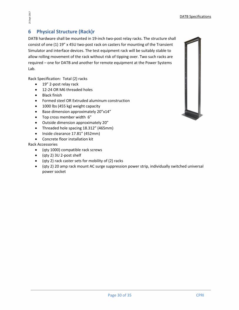
6 Physical Structure (Rack)r DATB hardware shall be mounted in 19-inch two-post relay racks. The structure shall
consist of one (1) 19” x 45U two-post rack on casters for mounting of the Transient
Simulator and interface devices. The test equipment rack will be suitably stable to
allow rolling movement of the rack without risk of tipping over. Two such racks are
required – one for DATB and another for remote equipment at the Power Systems
Lab.
Rack Specification: Total (2) racks
19” 2-post relay rack
12-24 OR M6 threaded holes
Black finish
Formed steel OR Extruded aluminum construction
1000 lbs (455 kg) weight capacity
Base dimension approximately 20”x14”
Top cross member width 6”
Outside dimension approximately 20”
Threaded hole spacing 18.312” (465mm)
Inside clearance 17.81” (452mm)
Concrete floor installation kit Rack Accessories
(qty 1000) compatible rack screws
(qty 2) 3U 2-post shelf
(qty 2) rack caster sets for mobility of (2) racks
(qty 2) 20 amp rack mount AC surge suppression power strip, individually switched universal power socket

DATB Specifications
Page 31 of 35 CPRI
25 S
ept
201
7
Figure 6-1 Rack mounts for DATB Equipment
7 Communication Network Communications within the CPRI campus shall utilize the CPRI backbone IP Network.
7.1 Network Performance Requirements
The DATB LAN and the SituTB WAN connections shall be 100/1000 Mbps Ethernet. The performance of
the overall network architecture shall be such that the critical clearing time requirements for various
control functions are guaranteed under all network loading conditions. The network performance shall
be completely predictable for operational behaviour.
Fiber optic cabling shall be used in the DATB equipment. Integrator shall provide all required fiber optic
cables, with a set of spare fiber optic cables sufficient to connect two additional IEDs to each rack.
7.2 Connection from DATB to the SGTB external transformer pad
Communication from DATB to equipment on the SGTB transformer pad shall be by fiber optic link to a
weather tight enclosure securely mounted on the transformer pad. 2” or larger conduit from DATB to
the transformer pad enclosure shall be installed. Pre-terminated indoor/outdoor 12 strand multimode
flat drop fiber optic cable pulled through the conduit shall terminate on each end at a panel of six dual
LC fiber terminations. Alternatively, CPRI may choose to field terminate the twelve fiber strands into the
dual LC terminations.
19" x 45U Rack structure for DATB equipment mount.NTS - Color only denotes intended use – all racks are black.
Racks 1 and 2 are on casters for mobility.
84
" (45
U)
Rack 1DATB
Rack 2PS Lab

DATB Specifications
Page 32 of 35 CPRI
25 S
ept
201
7
7.2.1 Fiber Link Specification
Option 1 - traditional field-termination: Cable:
OM2 or OM3 50/125 µm Multimode fiber Indoor / Outdoor rated 12-fiber count Loose Tube buffering, gel-free
Fiber Termination (Multiply by two in order to terminate both ends of cable): Small termination enclosure, single panel LC Connector pigtails (Qty 12) Connector panel w/ 6 duplex LC-Type connectors (Based on enclosure) Heat Shrink Splice Cover (Qty 12)
Option 2 - Use Connectorized cable with pre-terminated housing: Housing with 6 multimode Duplex-LC connectors pre-terminated to a 12-fiber multi-fiber connector (Quantity 2) Indoor/Outdoor OM3 50/125 µm multimode cable terminated with 12-fiber multi-fiber connector
7.3 SNMP Manager All DATB network components shall include an SNMPv3 Agent for device management by an SNMP
Manager. DATB shall include an SNMPv3 management system installed on the SituTB Workstation
Computer. Additional SNMP Managers may be installed on the DATB Portable Computers. Several
SNMP Managers are available at no or low cost for a system as small as SASTB:
SNMP Manager shall
Automatically detect network devices
Map network topology
Monitor for events (faults, availability, and performance) of network devices
Send event alerts via console display and email
Sequentially timestamp log entries
Provide search capability through system logs
Concurrently manage a minimum of 50 network devices
Run on the Windows 7 or Windows 10 station and portable computers
7.4 Redundancy Requirements
The DATB will not require redundancy in hardware or software.
7.5 Cyber Security Requirements for Distribution Automation
DATB shall utilize the existing CPRI campus IP network, with commercial cellular modems for off-campus
communication needs. Connection from the SGTB building to other campus buildings shall be by Virtual
DATB Specifications
Page 33 of 35 CPRI
25 S
ept
201
7
Private Network (VPN), with VPN supporting routers at each end of the connection. Connection to off-
campus locations shall be by VPN over cellular modem (see Figure 4.3).
The exchange of any information between systems shall include authentication of BOTH the source and
the receiver.
For communications using IEC 60870-5-104, the IEC 60870-5-7 standard that references IEC 62351-5 and
IEC 62351-3 shall be met.
Cryptographic key management shall be provided based on IEC 62351-9 requirements. Alternatively,
Public Key Infrastructure (PKI) may be used for key management.
Compliance with the cyber security recommendations in IEEE 1686 is required, including user ID and
password control, testing for adequate password strength, provision of audit capabilities for alarms and
events, monitoring of security-related activities, appropriate cryptographic technologies, and IED
configuration management.
8 Reliability and Availability vs. Flexibility The DATB is designed to provide a high level of testability and flexibility. IEDs and test equipment shall
be added and deleted from the DATB local and remote fixtures by CPRI Staff on a regular basis. As a
result, availability and reliability will be more a factor of the diligence of the operators than to the
quality of the components. Functional failures will not affect physical line hardware. The design will
stress this need for flexibility rather than extreme availability common in utility installations. Redundant
Requirements and definitions for reliability are defined in IEC 60870-4, chapter 3.1.
9 Contracting Options CPRI has three options in realizing the DATB:
Purchase, take delivery, assemble, and commission the DATB with internal CPRI staff.
Purchase and take delivery of the DATB hardware and software, then contract a knowledgeable
consultant to assemble and commission the DATB with assistance from UARC engineering staff.
Consultant would then provide training to UARC staff. Estimated 6-8 weeks manpower.
CPRI can contract the DATB to a Turnkey Contractor to assemble and commission the DATB for
delivery as a complete and working unit. A consultant would then be engaged to train UARC
staff on operation of the DATB. Conventional estimates for turnkey work are 1/3 material, 1/3
labor, and 1/3 profit, so a Turnkey assembly can be estimated as adding 2 * (material cost) to
the overall project cost.
The scope of work of the DASTB Turnkey Contractor shall include physical assembly, IED configuration,
and provisioning of 61850 SCL files as needed. It shall also include the engineering of the GOOSE and

DATB Specifications
Page 34 of 35 CPRI
25 S
ept
201
7
Sampled Value messages as required to implement the protection schemes, connection to the SituTB
SCADA WAN, and delivery and set-up of the DATB.
Design, installation, and commissioning of the 11kV Transformer Pad equipment and the 12-strand fiber
network connection from DATB to 11kV transformer pad will require a qualified integrator. This item is
to be contracted independent of the purchase of the balance of the DATB equipment.
10 Feature Quantities: Table 10-1 DATB Features List
# Feature Qty Section Notes
1 Rack Structure 2 6 19"x45U, (4) on casters
2 Router 4 4.6.8 Allow for (4) remote connections
3 Ethernet Switch 4 4.6.6 Each remote connection
4 Station Computer 1 4.6.2 Host for (1) Decentralized DA Scheme
5 Gateway 4 4.6.3 60870-5-104 to DNP3 or 61850
6 Remote Terminal Unit (small) 4 5 (16) DI, (8) DO, (16) AI, (8) AO
7 Remote Terminal Unit (large) 1 5 (40) DI, (60) DO, (80) AI, (8) AO
8 Portable computer 2 4.6.7 Dual LAN adapters
9 SituTB SCADA simulator 1 4.6.1 60870-5-104 master on laptop
10 SNMP Manager 1 7.3
11 12 strand fiber network link 1 7.2 CPRI Field Splice
12 Small Scale Simulation capability
1 4.2.1 Use Existing SASTB unit
11 Mapping Functions to Features (only for information) DATB enables CPRI to perform a list of Functions as specified in section 3. Each Function depends on a
subset of test bed Features. Each Feature has a cost associated with it. As funding permits, CPRI will
select “Buy”, “Use Existing”, or “Delay” for each Feature (Table 13-1). In this section we will create a
mapping of Functions to the required Features. This mapping will be used to populate the Function vs.
Feature Matrix (Table 11-2).
The Design of the DATB has generated a list of 15 Features to support 7 different Functions as itemized
in Table 11-2. This matrix will be manipulated in an Excel Spreadsheet to select the Features to be
realized.
Available Add Cost
Buy Yes Yes
Use Existing Yes No
Delay No No Table 11-1 Selection options for each Feature

DATB Specifications
Page 35 of 35 CPRI
1
2
3
4
5
6
7
8
9
10
11
12
13
14
15
16
17
Function List DATB Functions
Rac
k St
ruct
ure
Ro
ute
r
Eth
ern
et S
wit
ch
Stat
ion
Co
mp
ute
r
Gat
eway
Smal
l RTU
Larg
e R
TU
IEEE
15
88
tim
e so
urc
e
23
0 V
AC
UP
S
Po
rtab
le c
om
pu
ters
Situ
TB S
CA
DA
sim
ula
tor
Stan
dar
ds
for
refe
ren
ce
SNM
P M
anag
er
11
kV t
ran
sfo
rmer
pad
eq
uip
men
t
12
str
and
fib
er n
etw
ork
lin
k
Smal
l Sca
le S
imu
lati
on
cap
abili
ty
Wir
esh
ark
for
pac
ket
cap
ture
3.4.1 Generic Interconnection Model
3.4.2 Small scale simulation
3.4.3 Large scale simulation
3.4.4 Integration with SituTB SCADA/DMS
3.4.5 Integration with transformer pad switchgear
3.4.6 Observe 220kV and 33kV substation operation
3.4.7 Monitor information flow
Table 11-2 Function dependency on Features