detailed study of perforated beams with closely spaced...
TRANSCRIPT

Detailed Study of Perforated Beams with Closely Spaced Novel Web Openings
Konstantinos DanielTSAVDARIDISAcademic FellowCity University, London,United [email protected]
K.D. Tsavdaridis, received hisBEng and PhD degrees in CivilEngineering from City Universityand MSc (DIC) degrees inStructural Engineering fromImperial College, London. Hismain research interests are in theareas of perforated steel beamsconducting tests and FE analyses.
Cedric D’MELLOAssociate DeanCity University, LondonUnited [email protected]
Cedric D’Mello, obtained hisundergraduate and doctoraldegrees in Structural Engineeringfrom the University of Sussex. Hismain research interests are in theareas of composite structures andtesting of large scale civilengineering structures.
Summary
This paper presents a detailed study of the behaviour of perforated steel beams with closely spacedweb openings. Seven specimens including two typical cellular beams (i.e. circular web openings)and five perforated beams with novel web opening shapes were tested previously by the authors, toinvestigate the failure mode and load strength of the web-post between two adjacent web openings.These new novel web opening shapes improve the structural performance of the perforated beamswith respect to web-post buckling failure. In addition, the manufacturing procedure of these novelweb openings is improved and leads to sustainable design. The effects of web opening spacing/webopening depth of web-posts as well as the web opening depth/web thickness were studied toinvestigate the stability (slenderness) of the web-post subjected to vertical shear load. Incomparison with the conventional cellular beams, significant advantages were obtained.
Keywords: Perforated steel beams; cellular beams; non-linear finite element analysis; web-postbuckling; novel web opening shapes; web-post width; vertical shear capacity; parametric study;strut model; web-post stability
1. Introduction
The use of perforated steel beams has resulted in longer span floors. Their popularity has alsoincreased because of an architectural emphasis on exposed structures, with cellular, castellated andelongated web openings being typical in structural steel sections. Sections having webs penetratedby large closely spaced openings over almost the full span are now common. Although the bestapplication of these beams appears to be for long spans which are to carry a light uniform load,some heavy-mass structures, such as bridges, have been constructed using perforated beams for thefull span. Also, with greater automation, the cost of their fabrication has been reduced to the levelwhere for certain applications they may be competitive with open-web steel joists [1].
The last decade researchers examine standard web opening shapes (i.e. circular, rectangular andhexagonal) of perforated steel sections in order to provide a better understanding of the stressdistribution in the vicinity of the web openings [2,3]. The current work presents a furtherinvestigation on perforated beams with closely spaced non-standard elliptically-based novel webopening shapes as first proposed by Tsavdaridis and D’Mello [4].

The main aim is to provide the maximum possible web opening area for the integration of services,such as hydraulics pipes, electric wires, ventilation systems, etc., whilst keeping the minimumpossible self-weight. In addition, after separating and welding the top and bottom tee-sections, thehigher the second moment of area the higher is the capacity of the perforated beams under bending.Hence, perforated beams with closely spaced novel web openings are necessary, withoutcompromising the load carrying capacity of the web-post. This concept also leads to sustainablemanufacturing and consequently construction and the following points were initially addressed forthe design of the novel beams: i) design for minimum waste of material, ii) minimize energy isfabrication (i.e. oxy-cutting and welding) and in use and iii) aim for lean construction.
2. Aim of the work
The objective of this work was to examine the complex web-post buckling failure mode and thevertical shear capacity of web-post models. Initially, the FE model was validated against anexperimental programme of work. The failure modes of perforated sections and the positions ofhigh stress concentration points in the vicinity of the web openings were also considered. The aimwas achieved by conducting an extensive FE parametric study on the web-posts using a bucklingmodel that can be used for perforated sections with various closely spaced novel web openingshapes [4].
3. Experimental program to validate the FE model
3.1 Introduction
Experimental work was conducted on seven full scale steel perforated beams. Thereafter, theappropriate boundary conditions and input data were used in the FE study to simulate the local web-post failure for all of the web opening shapes.
3.2 Specimen details
The depth of the web openings should be low enough to prevent Vierendeel effects prior to web-post buckling failure in perforated sections with relatively thin webs. Hence, a diameter, do, equal to0.7h was used (Figure 1). The thickness of the stiffeners at supports is similar to the thickness of theflange (i.e. tf = 10.9mm), while the thickness of the stiffeners at mid-span is 20mm to allow forbetter stress distribution and avoid having stress concentration at the edges of the web openingsclose to the point load. Two different sets of tests were carried out as follows:
A circular cellular beam (A1) and two cellular beams with fillets of 25mm (A2) and 45mm (A3)introduced at the mid-depth of the web openings. With the advantage of profile cutting, thebigger the radius of the fillet, the larger is the depth of the final section and hence its secondmoment of area. (Table 1)
A circular cellular beam (B1), two perforated sections with novel vertical elliptically-based webopenings (B2 and B3) as well as one perforated section with novel inclined elliptically-basedweb openings (B4) symmetrically located to the mid-span. These web opening shapes consist ofa combination of circular and straight lines (Table 1).
Four web opening shapes of the first category and another thirty-two shapes of the second categoryhave been recently proposed and thoroughly examined for first time by Tsavdaridis [5]. It is worthnoting that although the full advantages of developing those opening shapes are obtained using theprofile manufacturing procedure, simple web cut-outs were considered for this research study inorder to limit the number of geometric parameters.

Fig. 1: Test arrangements, section properties and material properties
Table 1: The details of experimental tests
Specimen UB section Open. Type SpecificationsWeb Open.Spacing, S
Web-PostWidth (mm)
OpeningArea (mm2)
A1 457x152x52 Circular -----1,3do
94,5 77931A2 457x152x52 Filleted Circular r = 25mm of fillets 48 78361A3 457x152x52 Filleted Circular r = 45mm of fillets 15 79129B1 457x152x52 Circular -----
1,2do
63 77931B2 457x152x52 Vertical Elliptical THETA = 30 and R = 0,3do 63 56452B3 457x152x52 Vertical Elliptical THETA = 10 and R = 0,15do 63 32138B4 457x152x52 Inclined Elliptical THETA = 10 and R = 0,25do 63 45383
3.3 FE model description
Analysis of the web-post using the finite element method (FEM) was based on ANSYS v11.0.SHELL181 plastic elements were used for this work, with an average maximum size of 20mm inthe vicinity of the web openings. The elasto-plastic material properties of the FE models were keptthe same for all specimens. Young’s Modulus and Poisson’s Ratio equal to 200GPa and 0,3 wereassigned, respectively. For the plastic properties of the steel material, two options were considered:i) the average values from coupon tests were used (FEM 1 in Figure 3) as well as ii) a nominal yieldstrength value (fy=355MPa) was used for comparison (FEM 2 in Figure 3). The Tangent Modulusvalue was assumed to be 580MPa for both options. Initial imperfections with maximum amplitudeof tw/200 = 7,6/200 = 0,038 were also taken into account based on a previous study [5].
3.4 Test procedure
The test procedure followed was incrementally monotonic loading to failure, followed by fullunloading. The post-elastic failurebehaviour and the strain hardeningwere also examined. The apparatusfor the testing program was arrangedin such a way that a constant shear tomoment interaction at each web-postwas applied in all specimens. Dataacquisition equipment was used tomonitor the tests and alter the loadincrements for more precise results(Figure 2).
Fig. 2: Test set-up arrangement

3.5 Model verification
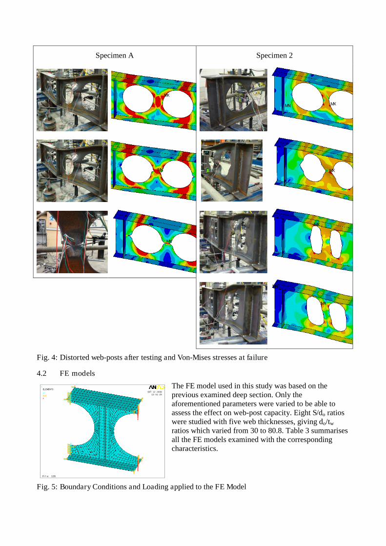
An indicative graph of the load versus deformation curves subjected to buckling load is presented inFigure 3. Table 2 summarizes the test to FE ratios for the yielding load, buckling (or critical) loadand ultimate loads as well as the failure modes of the tested specimens. This work led to thevalidation of the FE model, the use of the properties and assessment of the boundary conditions forthe development of the local web-post FE model. Figure 4 shows the highly distorted web-posts forevery specimen after failure together with schematic representation of Von-Mises stressesdistribution. Some deviation of the results between critical buckling loads calculated using FEA and
experimental buckling loads can be observed and isexplained by the geometric imperfections caused by themanufacturing process. Even very small imperfections cancause a substantial fall in the buckling load.
In the first category it was easily seen that when beamswith circular web openings with 45mm of fillet wereinvestigated, a very high stress concentration wasobserved at the notch point of the fillet. In the particularcase, web-post rupture was obtained at a relatively lowload level before any web-post buckling was observed. Inthe second category, the most important comparison isbetween Specimen B1 and B2 as the latter has almost 70%of the cellular’s web opening area, whilst its capacity is1,6 times the capacity of B1.
Fig. 3: Comparison of experimental and FEM results
Table 2: Summary of experimental and FEM results
Spec.at Py at Pcr at Pult. Max. δ at
Pcr (mm)
aPrimary FailureMode
bStrut-TieAngles
(degrees)Test/FE Test/FE Test/FE
A1 0,94 0,82 0,84 5,69 WPB 132/-44
A2 0,90 0,99 0,92 7,09 WPB 129/-44
A3 0,89 0,58 0,51 8,54 Mid-Post Rupture ---
B1 0,91 1,00 0,93 6,55 WPB 124/-50
B2 0,98 1,00 0,96 10,15 WPB (1 side) 135/-43
B3 0,98 1,20 0,97 6,92 WPB (1 side) 117/-54
B4 0,93 0,88 0,83 5,99 WPB (1 side) 127/-46aWPB: Web-Post BucklingbStrut-Tie Angles to the Horizontal Mid-depth Web-post Centre-line (Top Tee/Bottom Tee)
4. Parametric FE study
4.1 Introduction
The FEA was carried out for a range of parameters such as web opening shape, spacing and webslenderness. It included material and geometrical non-linearity similar to the validated model above.The FE model used considered of a short section of beam between the centre-line of adjacent webopenings. The ultimate strength of the web-post is governed by one of two modes: i) flexural failurecaused by the development of a plastic hinge in the web-post, or ii) buckling failure of the web-post(double-sided web curvature). The mode of failure is dependent on the geometry of the web-postand hence the web opening shape.
1
File: 126
OCT 12 200912:51:23
ELEMENTS
UROTF
Specimen A Specimen 2
MX
MN MX
MX MX
MX
MX
MN
MX
Fig. 4: Distorted web-posts after testing and Von-Mises stresses at failure
4.2 FE models
The FE model used in this study was based on theprevious examined deep section. Only theaforementioned parameters were varied to be able toassess the effect on web-post capacity. Eight S/do ratioswere studied with five web thicknesses, giving do/tw
ratios which varied from 30 to 80.8. Table 3 summarisesall the FE models examined with the correspondingcharacteristics.
Fig. 5: Boundary Conditions and Loading applied to the FE Model

The boundary conditions used in the model are shown in Figure 5. The web-flange connection wasassumed to be pinned as a safe lower bound, independent of the flange size and type of weld. Inpractice, some degree of fixity would exist, which increases the web buckling resistance.The nominal material properties of steel grade S355 used as before. The material model used theVon-Mises yield criterion with kinematic hardening which is suitable for most metals, includingsteel.
Table 3: Number of every FE model with corresponding characteristics
Specimen A-1 & B-1 Specimen B-2
3,9 5 6 7,6 10,5 3,9 5 6 7,6 10,5
1,1d o 31.5 0,21 0,27 0,34 0,5 0,64 0,931d o 31.5 0,105 0,166 0,198 0,285 0,321
1,2d o 63 0,29 0,45 0,53 0,67 0,75 1,031d o 63 0,177 0,293 0,347 0,422 0,524
1,3d o 94,5 0,34 0,47 0,6 0,72 0,94 1,131d o 94,5 0,236 0,361 0,461 0,562 0,702
1,4d o 126 0,33 0,51 0,64 0,9 1,1 1,231d o 126 0,283 0,482 0,556 0,672 0,855
1,5d o 157,5 0,36 0,69 0,76 0,95 1,23 1,331d o 157,5 0,279 0,549 0,604 0,824 1,018
1,6d o 189 0,45 0,68 0,83 1,03 1,46 1,431d o 189 0,308 0,553 0,687 0,87 1,205
1,7d o 220,5 0,44 0,73 0,86 1,1 1,53 1,531d o 220,5 0,404 0,576 0,786 1,044 1,341
1,8d o 252 0,44 0,73 0,91 1,25 1,7 1,631d o 252 0,358 0,635 0,776 1,04 1,464
Specimen A-2 Specimen B-3
3,9 5 6 7,6 10,5 3,9 5 6 7,6 10,5
N.A. N.A. N.A. N.A. N.A. N.A. N.A. 0,523d o 31.5 0,102 0,136 0,17 0,23 0,292
1,2d o 63 0,346 0,524 0,632 0,852 0,879 0,623d o 63 0,17 0,257 0,322 0,447 0,503
1,3d o 94,5 0,375 0,523 0,652 0,815 1,049 0,723d o 94,5 0,249 0,324 0,415 0,575 0,712
1,4d o 126 0,448 0,638 0,716 0,904 1,136 0,823d o 126 0,293 0,43 0,509 0,653 0,845
1,5d o 157,5 0,464 0,705 0,756 0,971 1,267 0,923d o 157,5 0,38 0,485 0,534 0,81 0,94
1,6d o 189 0,473 0,723 0,829 1,029 1,399 1,023d o 189 0,412 0,527 0,562 0,79 1,053
1,7d o 220,5 0,405 0,745 0,873 1,106 1,562 1,123d o 220,5 0,39 0,514 0,603 0,851 1,192
1,8d o 252 0.641 0,785 0,902 1,185 1,79 1,223d o 252 0,459 0,55 0,735 1,063 1,435
Specimen A-3 Specimen B-4
3,9 5 6 7,6 10,5 3,9 5 6 7,6 10,5
N.A. N.A. N.A. N.A. N.A. N.A. N.A. 0,65d o 31.5 0,139 0,176 0,233 0,337 0,383
N.A. N.A. N.A. N.A. N.A. N.A. N.A. 0,75d o 63 0,211 0,338 0,414 0,52 0,669
1,3d o 94,5 0,498 0,656 0,763 1,036 1,367 0,85d o 94,5 0,277 0,467 0,524 0,652 0,882
1,4d o 126 0,566 0,632 0,732 0,925 1,221 0,95d o 126 0,357 0,54 0,628 0,806 1,01
1,5d o 157,5 0,606 0,76 0,808 1,072 1,421 1,05d o 157,5 0,409 0,57 0,676 0,849 1,095
1,6d o 189 0,675 0,705 0,822 1,099 1,482 1,15d o 189 0,43 0,611 0,754 0,907 1,214
1,7d o 220,5 0,512 0,755 0,854 1,173 1,661 1,25d o 220,5 0,408 0,635 0,755 0,946 1,398
1,8d o 252 0,642 0,764 0,921 1,186 1,803 1,35d o 252 0,537 0,653 0,786 0,997 1,599
Width
(mm)
WEB THICKNESS, t w (mm)
WEB THICKNESS, t w (mm)
SWidth
(mm)
WEB THICKNESS, t w (mm)
SWidth
(mm)
WEB THICKNESS, t w (mm)
SWidth
(mm)
WEB THICKNESS, t w (mm)
SWidth
(mm)
WEB THICKNESS, t w (mm)Width
(mm)S
S
4.3 Design model
Compressive and tensile forces act across the web-post on opposite diagonals, as illustrated inFigure 6. Failure occurs when a local web buckle formed adjacent to the web opening as shown bythe shaded areas. The compressive stress acting on the strut was calculated using the force in theupper tee-section or half the applied vertical shear force for a symmetrically placed opening.
Fig. 6: Geometrical key parameters and strut model of web-post buckling

4.4 Results of the parametric FE study
The vertical shear capacities obtained from the FE analyses of the web-posts are graphicallyrepresented in Figure 7. Improved design formulas have been developed for perforated sectionswith circular web openings (A1 & B1) which cover the range of 1,1 ≤ S/do ≤ 1,8. As a result of the non-linear FE parametric study on 225 models presented in Table 3, similar formulas have beenproposed for perforated sections with the aforementioned novel web openings.
Fig. 7(a): Vertical shear resistance evaluated from FEA (Specimen A1/B1, A2 and A3)
Fig. 7(b): Vertical shear resistance evaluated from FEA (Specimen B2, B3 and B4)
4.5 Comparison of theoretical and FE results
The strut is considered to act diagonally across the member as shown in Figure 6. The effectivewidth, be, of the strut is always taken as half of the width of the web-post for use in determining thecompressive stresses (Equation 1). The effective length, le, of the strut is calculated as the diagonaldistance across the web-post using an effective length factor of 0,5 as assumed in the literature [6]for circular web openings (Equation 2). The slenderness, λ, of the web-post is then calculated asshown in Equation 3. This value of slenderness is used to obtain the compressive strength, pc, frombuckling curve ‘c’ of BS 5950-1 [7], which is appropriate for fabricated sections. The vertical shearresistance, Vv, due to web-post buckling is calculated as it is shown on Equation 4. Table 3 alsorepresents the comparison of the vertical shear forces evaluated by the basic design model found inthe literature and the FE model develop in this research study. There is conservatism up to 79% fornarrow and thin web-posts, but the level of conservatism is reduced for wider web-posts withgreater web thicknesses. The shaded areas indicate where the Vierendeel bending rather than theweb-post buckling controls.
be=0,5*So (1) le=0,5(So2 + do
2)0,5 (2) λ=le*(120,5)/tw (3) Vv=2*be*pc*tw=pc*So*tw (4)
4.6 Position of plastic hinges and effective widths of the web openings
Table 4 illustrates the position of the plastic hinges in terms of an angle φ and so the effectiveopening widths for circular and elliptically-based web opening shapes. The positions of plastic

hinges are estimated from models with not too closely spaced web openings to avoid havingtransfer of stresses between the edges of two adjacent web openings.
Table 4: Summary of equivalent effective widths for novel web openings
Specimenφ range
(degrees)Due to Vierendeel action Due to web-post buckl. action Max. used
φ(degrees)φ(degrees) Eff. open. width φ(degrees) Eff. open. width
A1/2/3 & B1B2B3B4
20-2913-2212-2215-30
28221221
0,25do
0,18do
0,1do
0,18do
2817
12-1417-45
0,25do
0,14do
0,1-0,13do
0,15-0,28do
28221221
do: Web opening depth
5. Conclusions
The conclusions from the parametric FE work conducted on 225 models are:
Some specimens are governed by Vierendeel bending capacity when the web thickness isbetween 7,6mm < tw < 10,5mm and the web-post width is between 63mm < so < 252mm. Ingeneral, when novel elliptically-based web openings are considered, the critical openings lengthis narrower and hence the Vierendeel capacity is high.
From the Figure 7 it can be seen that in general the vertical shear capacities increase as the web-post width is increased, and conversely slightly decreased when they are subjected to highVierendeel bending forces. However, when narrow elliptically-based web openings areconsidered, the capacity only gradually increases as Vierendeel bending is not critical.
The existence of the fillets at the mid-height of the web opening with different radiuses such asSpecimens A2 and A3, does not affect the vertical shear capacity of the web-posts. In fact, theybehave similarly beyond a certain web-post width.
The maximum shear stresses are lower in Specimens B3 and B4 for any web opening spacingand Specimen B2 when the web opening spacing is greater than 1,131do, due to better stressdistribution.
The maximum shear stresses move from the mid-height of the web-post towards the centroid ofthe axial forces and closer to the flanges, for relatively wide web opening spacing.
6. References
[1] Zaarour W., Redwood R., “Web buckling in thin webbed castellated beams”, Journal ofStructural Engineering, Vol.122, No.8, 1996, paper 11030.
[2] Chung K.F., Liu T.C.H., Ko A.C.H., “Steel beams with large web openings of variousshapes and sizes: an empirical design method using a generalized moment-shear interaction”,Journal of Constructional Steel Research, Vol. 59, 2003, pp. 117-1200.
[3] Tsavdaridis K.D., and D’Mello C., “Vierendeel Bending Study of Perforated Steel Beamswith Various Novel Shapes of Web Openings, through Non-linear Finite ElementAnalyses”, ASCE Journal of Structural Engineering, 2011. (DOI:10.1061/(ASCE)ST.1943-541X.0000562)
[4] Tsavdaridis K.D., and D’Mello C., “Web Buckling Study of the Behaviour and Strength ofPerforated Steel Beams with Different Novel Web Opening Shapes”, The Journal ofConstructional Steel Research, Vol. 67, Issue 10, 2011, pp. 1605-1620.
[5] Tsavdaridis, K.D., “Structural Performance of Perforated Steel Beams with Novel WebOpenings and with Partial Concrete Encasement”, City University, London, 2010.
[6] Ward J.K., “Design of composite and non-composite cellular beams”, The SteelConstruction Institute, 1990, SCI P-100.
[7] British Standard Institution. BS5950-1: 2000, “Structural use of steelworks in building”, BSI.