detecting and interpreting localized corrosion using...
TRANSCRIPT

DETECTING AND INTERPRETING LOCALIZED CORROSION USING CORRTRAN® MV
orrTran MV uses electrochemical noise measurements to give an indication of localized corrosion susceptibility of the probe
material in the process environment. This paper by Dr. K.Hladky, the inventor of the electrochemical noise measurement technique, discusses the measurement approach used by CorrTran MV and shows how to interpret the results obtained from this device.
C
Detecting and Interpreting Localized Corrosion using CorrTran MV
Pepperl+Fuchs Inc. Twinsburg 1 5/13/2008
1. INTRODUCTION
The CorrTran MV device uses electrochemical noise measurements to give an indica-tion of localized corrosion susceptibility of the probe material in the process environ-ment. The purpose of this note is to give some additional background information of the measurement approach used by the CorrTran MV and to assist in the interpretation of results obtained from this device.
2. MEASUREMENT TECHNIQUE BACKGROUND
Electrochemical noise techniques rely on measurement of short-term fluctuations of either the electrode potential or of the coupling current between two similar electrodes, to give an indication of localized corrosion attack susceptibility. Both approaches have their advantages and disadvantages – measurement of fluctua-tions of the electrode potential is sensitive to detection of the onset of localized corrosion initiation even before a pit is visible, whereas coupling current measurements are sensitive to detection of the development and early growth of localized attack. Although CorrTran MV would be able to support both types of electrochemical noise measurement, only the coupling current method is implemented. The current between two of the probe electrodes, effectively shorted together, is monitored over a period of time and statistical parameters of its behavior are recorded and analyzed. The reason for this choice of measurement is that in practical applications it is more useful to provide an indication of sustained localized corrosion attack, such as the formation and propagation of pits, rather than to detect short term initiation events, such as small breaks in the protective oxide film which usually quickly re-heal and do not result in a significant metal loss. Although the measurement techniques and the mathematical analysis of the results are well tested and documented, there is no ‘standard’ method of presentation of a single ‘pitting index’ parameter, summarizing the susceptibility of the probe material to localized corrosion attack in a way easily to be presented to the end user. CorrTran MV outputs a normalized localized corrosion index variable, scaled as to always range from a value of between zero and one. This is calculated as the ratio of the standard deviation of the coupling current to the root-mean-square (RMS) value of this current, both measured over a period of time. The RMS value includes any mean (DC) component of the coupling current. The measurement method settings (sample period, number of samples etc.) were extensively tested and optimized during the development of CorrTran MV to give a

Detecting and Interpreting Localized Corrosion using CorrTran MV
Pepperl+Fuchs Inc. Twinsburg 2 5/13/2008
satisfactory output in a wide range of probe material and process environment combinations. The localized corrosion measurement is extremely sensitive and that there are many factors which can lead to the localized corrosion index showing a higher value in an individual measurement cycle. Results obtained during the development of the CorrTran show that a localized corrosion index of above 0.3, sustained over a length of time (hours/days), is a reliable indicator of localized corrosion occurring on the probe electrodes.
3. TYPICAL EXAMPLES OF LOCALIZED CORROSION MEASUREMENT RESULTS
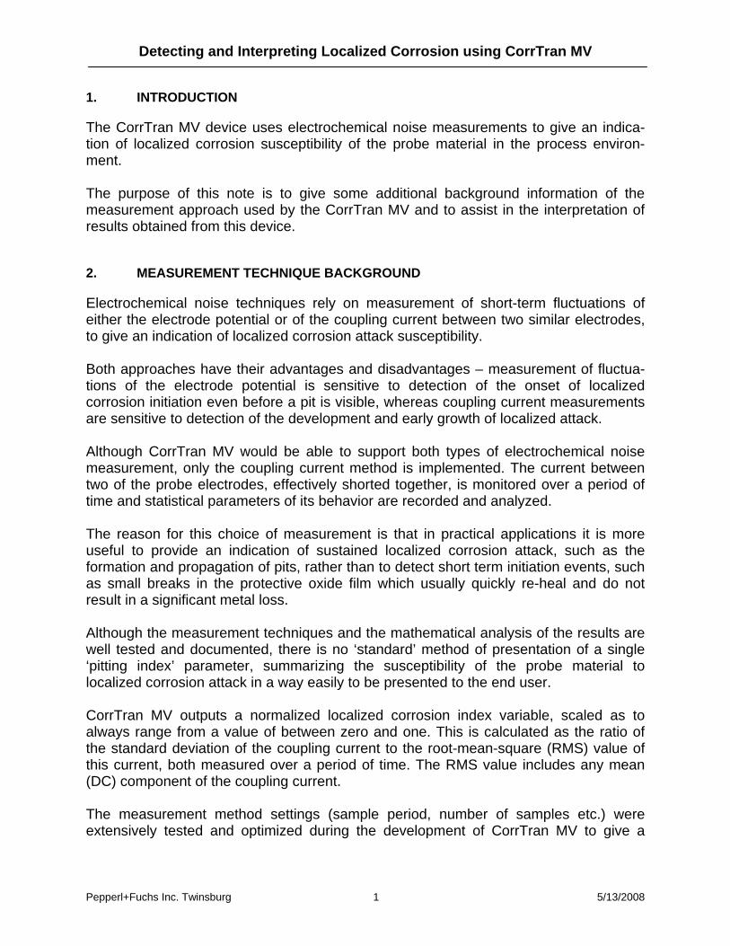
3.1. General corrosion
During general corrosion attack, the anodic and cathodic areas are close to each other on a microscopic scale. Although the metal dissolution is never perfectly uniform because of the microstructure of the material, surface roughness etc., this type of corrosion attack gives a low localized corrosion index output, typically in the 0 to 0.1 range. In this case the standard deviation of the electrode coupling current is low and the mean value is much higher, therefore the localized corrosion index output is also low. There may be occasional peaks of over 0.3 in magnitude, but these are often caused by process changes and usually also correspond to changes in the measured corrosion rate. The example plot below shows an output typical of general corrosion. The measured corrosion rate (blue) is between 30 and 35 mpy and has a distinct daily variation caused by ambient temperature changes. The localized corrosion index (red) is very low at about 0.05, indicating the absence of localized corrosion attack.
Detecting and Interpreting Localized Corrosion using CorrTran MV
Pepperl+Fuchs Inc. Twinsburg 3 5/13/2008
General Corrosion
0.0
5.0
10.0
15.0
20.0
25.0
30.0
35.0
40.0
45.0
50.0
25-Mar-07 26-Mar-07 27-Mar-07 28-Mar-07 29-Mar-07 30-Mar-07
Cor
rosi
on R
ate
[mpy
]
0.0
0.1
0.2
0.3
0.4
0.5
0.6
0.7
0.8
0.9
1.0
Loca
lised
Cor
rosi
on In
dex
Figure 1: Typical example of high general and low localized corrosion rates
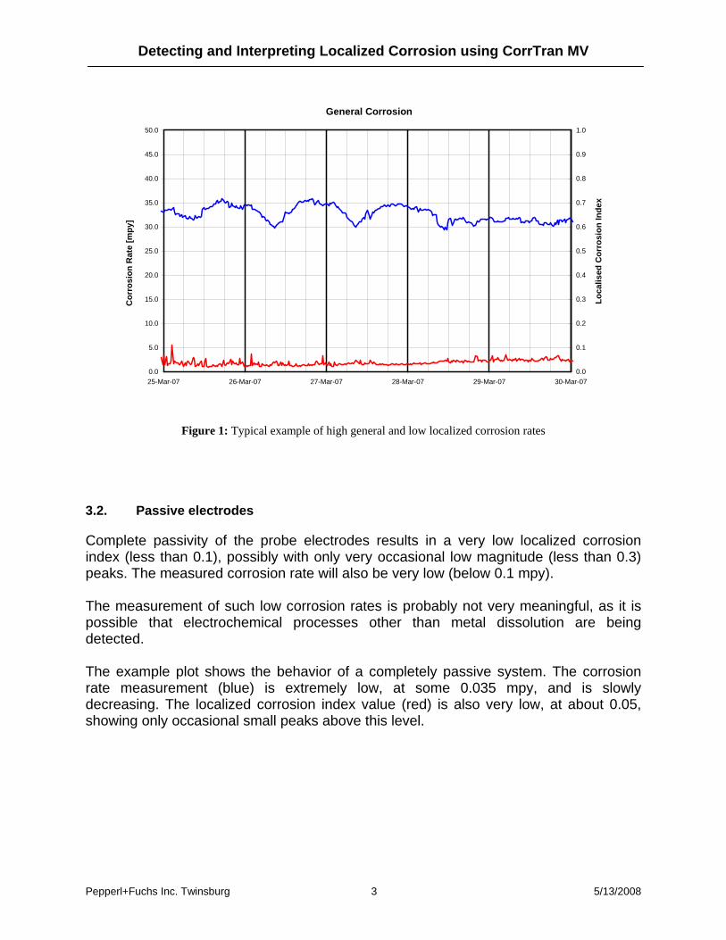
3.2. Passive electrodes
Complete passivity of the probe electrodes results in a very low localized corrosion index (less than 0.1), possibly with only very occasional low magnitude (less than 0.3) peaks. The measured corrosion rate will also be very low (below 0.1 mpy). The measurement of such low corrosion rates is probably not very meaningful, as it is possible that electrochemical processes other than metal dissolution are being detected. The example plot shows the behavior of a completely passive system. The corrosion rate measurement (blue) is extremely low, at some 0.035 mpy, and is slowly decreasing. The localized corrosion index value (red) is also very low, at about 0.05, showing only occasional small peaks above this level.

Detecting and Interpreting Localized Corrosion using CorrTran MV
Pepperl+Fuchs Inc. Twinsburg 4 5/13/2008
Passive Conditions
0.000
0.005
0.010
0.015
0.020
0.025
0.030
0.035
0.040
0.045
0.050
07-Oct-07 08-Oct-07 09-Oct-07 10-Oct-07 11-Oct-07 12-Oct-07
Cor
rosi
on R
ate
[mpy
]
0
0.1
0.2
0.3
0.4
0.5
0.6
0.7
0.8
0.9
1
Loca
lised
Cor
rosi
on In
dex
Figure 2: Typical example of a passive system
3.3. Pit initiation – passive film reforming
In this case, microscopic flaws in the protective passive film give rise to random localized metal dissolution. The disrupted passive film however reforms and the corrosion does not propagate. The localized corrosion index output level will in this case be fluctuating, significantly above zero, often exceeding the 0.3 value. Bursts of noise may be observed but these will correlate to changes in the process conditions and corrosion rate. The measured corrosion rate will also be low. The example shown below presents data obtained in a laboratory test to assess the variation of susceptibility to localized corrosion attack with changing temperature. The temperature of the solution (blue) is increased stepwise and the corrosion rate (red) and localized corrosion index (green) are recorded. The results show that the corrosion rate increases with temperature from some 0.0004 mm/y (0.016 mpy) at 20°C to about 0.0008 mm/y (0.032 mpy) at 60°C. The localized corrosion index remains at a low value (0.1) at temperatures of below 45°C. It then begins to rise rapidly to a value of over 0.8 as the temperature reaches 60°C. As the solution is allowed to cool, the localized corrosion index value drops back to 0.1, indicating that pitting attack had ceased.

Detecting and Interpreting Localized Corrosion using CorrTran MV
Pepperl+Fuchs Inc. Twinsburg 5 5/13/2008
Figure 3: General corrosion rate over temperature (example)
Figure 4: Localized corrosion rate over temperature (example)

Detecting and Interpreting Localized Corrosion using CorrTran MV
Pepperl+Fuchs Inc. Twinsburg 6 5/13/2008
Figure 5: Applied temperature profile
3.4. Pit propagation
This is potentially the most dangerous situation. A large number of pits are initiating and eventually one or more progress to the propagation and rapid growth stage. This is the situation the CorrTran MV is optimized to detect accurately. This situation will give a high localized corrosion index output (0.6 to 0.9). Although there may be occasional dips and peaks to outside of this band, the output will be consistently high. The corrosion rate reading will be low to moderate (0.1 to 10 mpy).

Detecting and Interpreting Localized Corrosion using CorrTran MV
Pepperl+Fuchs Inc. Twinsburg 7 5/13/2008
Figure 6: General corrosion during pit propagation
Figure 7: Typical localized corrosion index readings during pit propagation

Detecting and Interpreting Localized Corrosion using CorrTran MV
Pepperl+Fuchs Inc. Twinsburg 8 5/13/2008
The example plot shows typical output of actively pitting probe electrodes. The corrosion rate (red) is low at about 0.025 mm/y (1 mpy). The localized corrosion index output (green) shows a high value (0.7 to 0.9), sustained over a period of some 50 or more hours. 3.5. Crevice corrosion
It is possible for crevice corrosion to occur at the sealing o-ring between the removable probe element and its mounting stud. This is usually a consequence of a pit initiating in that location which then propagates as crevice attack. If the process conditions are such that it is possible for crevice corrosion to occur on the CorrTran MV probe then it is also likely that crevice corrosion will occur elsewhere in the monitored plant, in locations such as at flange gaskets, under sediment or debris deposits etc. Crevice corrosion has unique ‘noise’ signature of periodic oscillation of the electrode potential or of the coupling current. The oscillations can be of quite high amplitudes and can persist for several hours or more. They are easily identifiable in the ‘raw’ noise data. While these oscillations are ‘averaged out’ in the CorrTran MV, the resulting observed localized corrosion index output will be a series of very high peaks (0.8 or more) superimposed on a generally low (less than 0.3) baseline. Each individual peak corresponds to a time period of oscillations of the raw noise input, as detected during an individual CorrTran MV measurement cycle.

Detecting and Interpreting Localized Corrosion using CorrTran MV
Pepperl+Fuchs Inc. Twinsburg 9 5/13/2008
Crevice Corrosion
0.0
1.0
2.0
3.0
4.0
5.0
6.0
7.0
8.0
9.0
10.0
25-Mar-07 26-Mar-07 27-Mar-07 28-Mar-07 29-Mar-07 30-Mar-07
Cor
rosi
on R
ate
[mpy
]
0.0
0.1
0.2
0.3
0.4
0.5
0.6
0.7
0.8
0.9
1.0
Loca
lised
Cor
rosi
on In
dex
Figure 8: Typical example of a crevice corrosion attack showing both general corrosion (blue) and localized
corrosion (red) This example plot shows behavior typical of crevice corrosion attack on one of the probe elements. The measured corrosion rate (blue) is moderate at between 6 and 8 mpy and shows a degree of fluctuation. The localized corrosion index value (red) varies considerably, peaking from a baseline of between 0.1 and 0.2 to values in excess of 0.9. There is little, if any, correlation between the timing of these peaks and the corrosion rate fluctuations.
4. POSSIBLE SOURCES OF ERROR
There are a few situations where the CorrTran MV localized corrosion index may show unusual or possibly misleading values. In a majority of these the cause will be either a bad choice of probe location or a problem with the probe electrodes. The CorrTran MV employs an electrochemical measurement both for the corrosion rate determination and for the localized corrosion index. An ionically conductive path must exist between the probe electrodes in order for the measurement to succeed. A completely ‘dry’ probe could possibly give a significant localized corrosion index output. This will simply be a result of a very low standard deviation value divided by a very low RMS value. However, in this case the measured conductance will be extremely

Detecting and Interpreting Localized Corrosion using CorrTran MV
Pepperl+Fuchs Inc. Twinsburg 10 5/13/2008
low and the CorrTran MV general corrosion rate and the localized corrosion index outputs will be set to zero, indicating that a corrosion measurement is not possible. A partly immersed probe can give misleading results. This is because the ‘water line’ then present on the probe elements will not be constant because of flow, vibrations etc. This fluctuation then results in a high standard deviation of the coupling current and hence in an erroneously high localized corrosion index output. Air or gas bubble impingement on the probe electrodes can also give an unusually high localized corrosion index output, very much for the same reasons. Crevice corrosion can occur at the o-rings sealing the probe elements to their mounting studs. Care should be taken in during the probe installation, making sure that the o-ring seals and the probe elements are not contaminated and are fitted correctly.

Detecting and Interpreting Localized Corrosion using CorrTran MV
Pepperl+Fuchs Inc. Twinsburg 11 5/13/2008
5. CONCLUSION
CorrTran MV is an extremely sensitive and sophisticated device capable of accurate corrosion measurements. However, as with all probe type corrosion measurement devices, it only directly measures the corrosion rate and behavior of the probe elements, not of the plant structure itself. For this reason, it is very important that the actual location of the CorrTran MV probe in the monitored plant is carefully chosen to be representative of the typical prevailing process conditions. The CorrTran MV localized corrosion index output may be used to reliably identify plant conditions when localized corrosion attack is likely to occur. Simple interpretation of the variation of this output with time can provide further information as to the type and severity of this type of corrosion attack. Note: some results and especially figures 3…7 are used courtesy of Dr. Helga Leonhard and Thomas Weigelt of TÜV SÜD Chemie Service GmbH, Frankfurt am Main, Germany