detecting sparks, extinguishing sparks! - cmc · pdf file · 2017-05-10detecting...
TRANSCRIPT
Detecting Sparks, Extinguishing Sparks!
we HAve THe rIGHT soluTIonsFor All ApplIcATIons.
06.2
012
© 2
000
by
T&B
ele
ctro
nic
Gm
bH
. A
ll ri
gh
ts r
eser
ved
.
In Operatio
n
000
000
000
16:19:39
16.12.09
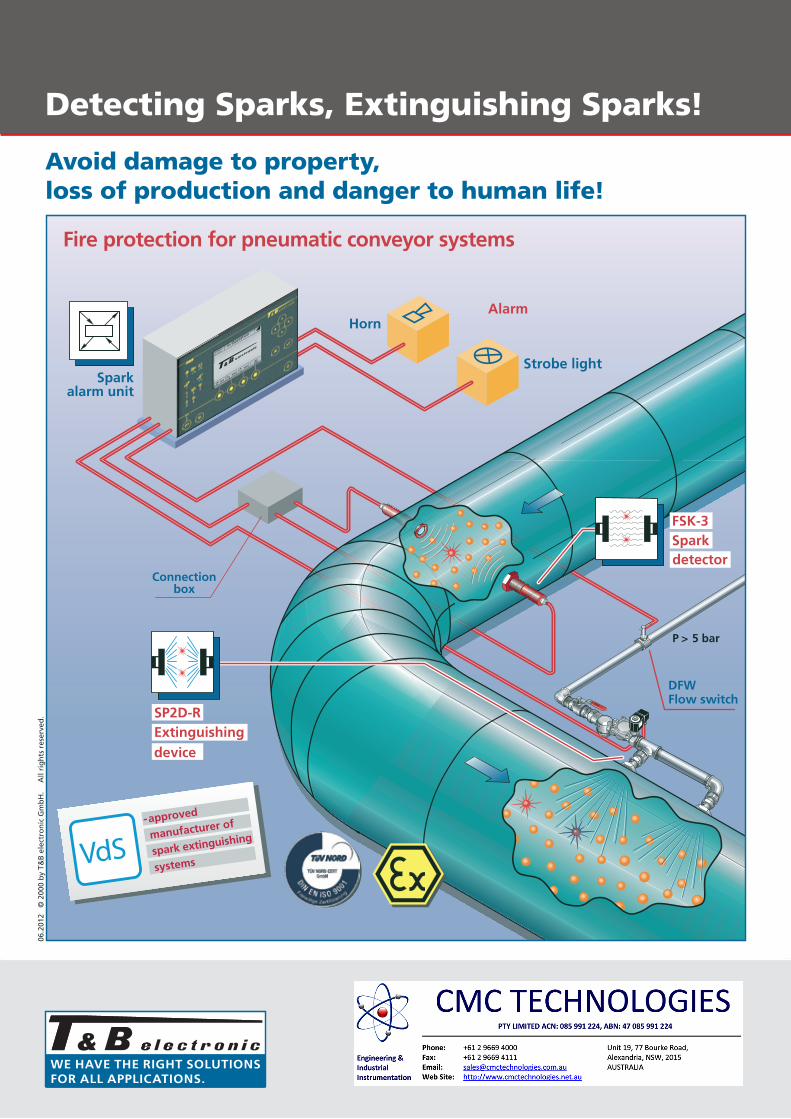
P > 5 bar
AlarmHorn
DFWFlow switch
Strobe light
Connectionbox
Fire protection for pneumatic conveyor systems
VdS-approved
manufacturer of
spark extinguishing
systems
Sparkalarm unit
SP2D-RExtinguishing
FSK-3Spark
device
detector
Avoid damage to property, loss of production and danger to human life!
we HAve THe rIGHT soluTIonsFor All ApplIcATIons.
Igniting spark
H3 B3Horn Strobe light
TH1Exterior
thermostat
HBWHeating
tape
Fan
5 b
ar
DFWFlow
switchVB1 Water tank
WDS Pressure booster system
C
Conveying line
E
F
G
D
Connection boxes forAG1 Heating band
BA
HIn Operation
000 000 000
16:19:3916.12.09
Klemmenkasten-Nr. ...........................
Melder-Nr. .........................................
Funkenlöschanlage
Linien-Nr. ...........................................
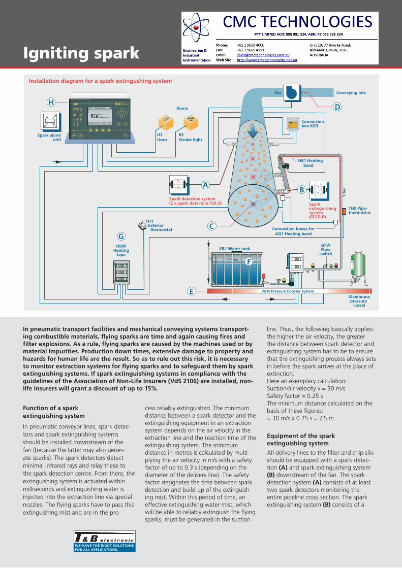
Installation diagram for a spark extingushing system
Alarm
Connection
Spark alarmunit
box KK3
HB1 Heatingband
TH2 Pipe-thermostat
Membranepressure
vessel
Spark detection system(2 x spark detectors FSK-3) Spark
extinguishingsystem (SP2D-R)
In pneumatic transport facilities and mechanical conveying systems transport-ing combustible materials, flying sparks are time and again causing fires and filter explosions. As a rule, flying sparks are caused by the machines used or by material impurities. production down times, extensive damage to property and hazards for human life are the result. so as to rule out this risk, it is necessary to monitor extraction systems for flying sparks and to safeguard them by spark extinguishing systems. If spark extinguishing systems in compliance with the guidelines of the Association of non-life Insurers (vds 2106) are installed, non-life insurers will grant a discount of up to 15%.
Function of a spark extinguishing system
In pneumatic conveyor lines, spark detec-tors and spark extinguishing systems should be installed downstream of the fan (because the latter may also gener-ate sparks). The spark detectors detect minimal infrared rays and relay these to the spark detection centre. From there, the extinguishing system is actuated within milliseconds and extinguishing water is injected into the extraction line via special nozzles. The flying sparks have to pass this extinguishing mist and are in the pro-
cess reliably extinguished. The minimum distance between a spark detector and the extinguishing equipment in an extraction system depends on the air velocity in the extraction line and the reaction time of the extinguishing system. The minimum distance in metres is calculated by multi-plying the air velocity in m/s with a safety factor of up to 0.3 s (depending on the diameter of the delivery line). The safety factor designates the time between spark detection and build-up of the extinguish-ing mist. Within this period of time, an effective extinguishing water mist, which will be able to reliably extinguish the flying sparks, must be generated in the suction
line. Thus, the following basically applies: the higher the air velocity, the greater the distance between spark detector and extinguishing system has to be to ensure that the extinguishing process always sets in before the spark arrives at the place of extinction.Here an exemplary calculation:Suction/air velocity v = 30 m/sSafety factor = 0.25 sThe minimum distance calculated on the basis of these figures:= 30 m/s x 0.25 s = 7.5 m
equipment of the spark extinguishing system
All delivery lines to the filter and chip silo should be equipped with a spark detec-tion (A) and spark extinguishing system (B) downstream of the fan. The sparkdetection system (A) consists of at leasttwo spark detectors monitoring theentire pipeline cross section. The sparkextinguishing system (B) consists of a

we HAve THe rIGHT soluTIonsFor All ApplIcATIons.
Fire protection
Sparkdetector
1. By-pass smoke detector in return air duct2. Spark detection in the suction pipe3. Spark extinguishing in the suction pipe
By-passsmoke detector
4. Thermal detector in discharge area5. Filter extinguishing system6. Spark and thermal detection
1
Roof
Floor
6
4 5
3 2
Extinguishingdevice
Thermal-detector
Clean air ducts
Protection of a Hose filter systems: All suction pipes leading to the filter system are monitored by spark detectors (2) and protected byspark extinguishers (3).If a filter pipe startssmouldering, the alarmis actuated immedi-ately by by-pass smokedetectors (1) in theclean air ducts. Firesdue to self-ignition inthe filter system aredetected by thermaldetectors (4) an thealarm given immedi-ately, so that the filterextinguishing system(5) is also activated.
quick-opening solenoid valve and at least one extinguishing nozzle. The extinguish-ing nozzles are provided with a shutting device to protect them from soiling. The extinguishing process is continued until the last detected spark (c) has passed the extinguishing section; then the automatic extinguishing system closes independently. However, the spark extinguishing system continues to remain ready for operation, so that newly arising flying sparks can immediately be combatted again. The minimum extinguishing time amounts to five seconds and is automatically extended in case of persistent flying sparks. During the production process, individual sparks are reliably extinguished. It is possible to effect a machine shut-down (D) by means of an adjustable spark threshold compris-ing between 1 and 999 sparks within a time unit. The number of sparks detected and the triggering threshold are visually displayed in the spark detection centre. So as to be able to generate a perfect spray pattern, a flow pressure of at least 5 bar must be present at the automatic extin-guishing system. If that is not the case, a pressure booster (e) consisting of a vertical centrifugal pump with diaphragm pressure tank and a storage tank (F) will be used. The storage tank simultaneously serves to biologically separate mains water and ex-tinguishing water. The extinguishing water can be connected to an existing sprinkler system. Extinguishing systems that are located in areas threatened by frost must be equipped with an electric trace heating. The trace heating (G) is controlled via an external thermostat with the associated heating strip monitoring system. All heated extinguishing water lines and the extin-guishing system itself must be insulated. In the area around the valves and extinguish-ing nozzles, it must be possible to detach the insulation for maintenance purposes. The spark detectors are equipped with built-in test facilities. The new generation of spark detection centres (H) is equipped with an automatic detector test facility and the manual detector test is dispensed with in this case.
An extinguishing water monitoring system is constantly monitoring whether extinguishing processes are proceeding correctly and visually displays the extin-guishing process at the spark detection centre.
If a filter system is working with an air return system, bypass smoke detectors are provided for installation in the return air ducts. These will immediately report any smouldering fires in the filter hoses and cause the fans to be switched off. Two differential temperature indicators are additionally installed in the filter system and immediately trigger at a temperature > 85°C. It is possible to only trigger analarm or to also actuate an extinguishingsystem. The spark detection centres areequipped with a microprocessor monitor-ing system. The results of the fire detec-tion events and malfunctions are savedand displayed as plain text. Up to 2500results can be saved.
Directives
The Association of Non-Life Insurers ap-plies the directive for spark extinguishing systems (VdS 2106).
It stipulates among others that a spark extinguishing system may only be installed by an installation company that has been approved by the VdS. Only approved components and equipment may be used. For every spark extinguishing system, the approved installation company must
compile an installation test, a schematic drawing detailing function and protected area as well as a hydraulic calculation. These documents must be submitted to the VdS during an acceptance proce-dure. Spark extinguishing systems must be checked and serviced by an approved installation company at regular intervals. Any defects detected must be immedi-ately eliminated. Normally, maintenance at six-monthly intervals is adequate. The company operating the spark extinguish-ing system must maintain a logbook into which malfunctions, technical inspections, etc. are entered.
we HAve THe rIGHT soluTIonsFor All ApplIcATIons.
Spark detectors | Automatic extinguishing system
**FSK-3**FST-3
**FSL-3
**SP1D-R
**SP2D-R
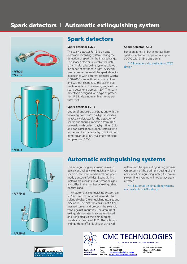
Spark detectorsspark detector FsK-3
The spark detector FSK-3 is an opto-electronic recording system serving the detection of sparks in the infrared range. The spark detector is suitable for instal-lation in closed pipeline systems without incidence of extraneous light. A special bracket serves to install the spark detector in pipelines with different nominal widths (100-2000 mm) without any difficulties and without changes to the existing ex-traction system. The viewing angle of the spark detector is approx. 120°. The spark detector is designed with type of protec-tion IP 65. Maximum ambient tempera-ture: 60°C.
spark detector FsT-3
Design of enclosure as FSK-3, but with the following exceptions: daylight insensitive heat/spark detector for the detection of sparks and thermal radiation from 300°C onwards, with built-in daylight filter. Suit-able for installation in open systems with incidence of extraneous light, but without direct solar radiation. Maximum ambient temperature: 60°C.
spark detector Fsl-3
Function as FSK-3, but as optical fibre spark detector for temperatures up to 300°C with 3 fibre optic arms.
**All detectors also available in ATEX design
Automatic extinguishing systemsThe extinguishing equipment serves to quickly and reliably extinguish any flying sparks detected in mechanical and pneu-matic transport facilities. Extinguishing systems are available in different designs and differ in the number of extinguishing nozzles used.
An automatic extinguishing system, e.g. SP2D-R, consists of a ball valve, dirt trap, solenoid valve, 2 extinguishing nozzles and pipework. The dirt trap consists of a fine-meshed screen and protects the solenoid valve against impurities. The amount of extinguishing water is accurately dosed and is injected via the extinguishing nozzle at an angle of 120°. The optimum extinguishing effect is already achieved
with a few litres per extinguishing process. On account of the optimum dosing of the amount of extinguishing water, the down-stream filter systems will not be adversely affected.
**All automatic extinguishing systems also available in ATEX design

we HAve THe rIGHT soluTIonsFor All ApplIcATIons.
Spark detection centre
Spark detection centre BM 6
Microprocessor-controlled spark detection centre for 2 to max. 36 monitoring/extin-guishing areas. Modular design in different versions:
n BM 6-2: upgraded for 2 lines
n BM 6-4: upgraded for 4 lines
n BM 6-16 and BM 6-36: Basic versionupgraded for 4 lines, later expansionto 16 or 36 lines is possible at any timethrough the use of further compo-nents.
n 4 operating languages are pre-installedand can be switched over at any time.
n Up to 2,500 events can be stored inthe log memory. All messages areshown in plain text.
n Connection of up to 4 spark detectorsper line is possible.
n The number of detected sparks, theextinguishing time as well as machineshutdowns are recorded and displayed.
n Automatic self-monitoring of the entirespark detection and extinguishing sec-tion. The spark detectors are automati-cally tested at regular intervals.
n If a line is switched off, this will bevisually displayed and recorded.
n All relay outputs (alarm, post-de-tection, malfunction, etc.) are freelyprogrammable. Per area, 2 floatingoutputs 230 V/1 A are available.
n Visual display for an optional traceheating for the extinguishing water.
n Built-in emergency power supply for anoperating time of 4 hours.
n Enclosure type of protection: IP 55
n An optional OPC interface is avail-able for relaying events and for dataexchange with other systems.
n A remote control function makes itpossible to access the control centrevia the Internet. On account of this,the T&B service is able to interveneonline, providing support in the eventof a malfunction, if a correspondingmodem connection is ensured.
we HAve THe rIGHT soluTIonsFor All ApplIcATIons.
Installation Instructions for Spark Extinguishing Systems
1NYM 3 x 1,5
HO5 WF 3 x 1,5NYM 10 x 1,5
Fan switch out
NYM 5 x 2,5400 V/50 Hz/16 A
NYM 10 x 1,5
230 V/50 Hz/ 10 A
NYM 3 x 1,5
NY
M
4 x
1,5
Fan
NYM 3 x 1,5
15
9
NYM 3 x 1,5
8 5
Galvanisedwater pipe
DIN 2440DIN 2950Copper pipeDIN 1786
2
Extinguishingdevice
Connectionbox
DFWFlow
switch
4
Spark detector
NYM 3 x 1,5NYM 3 x 1,5
LIYCY 7 x 0,5 screened 3
6
14
11
10
12
17
16
13
VB1 Water tank
NYM 3 x 1,5
19
WDS Pressure booster system
18
P = 7,5 kW
NYM 5 x 4,0400 V/50 Hz/25 A
7
In Operation
000 000 000
16:19:3916.12.09
Klemmenkasten-Nr. ...........................
Melder-Nr. .........................................
Funkenlöschanlage
Linien-Nr. ...........................................
Heating bandHB1
TH1Exterior
HBWHeating
tapemonitor
Membranepressure
vessel
thermostat
Connection boxesfor AG1 Heating band
TH2Pipethermostat
Alarm
Horn Strobe light
Sparkalarm unit

we HAve THe rIGHT soluTIonsFor All ApplIcATIons.
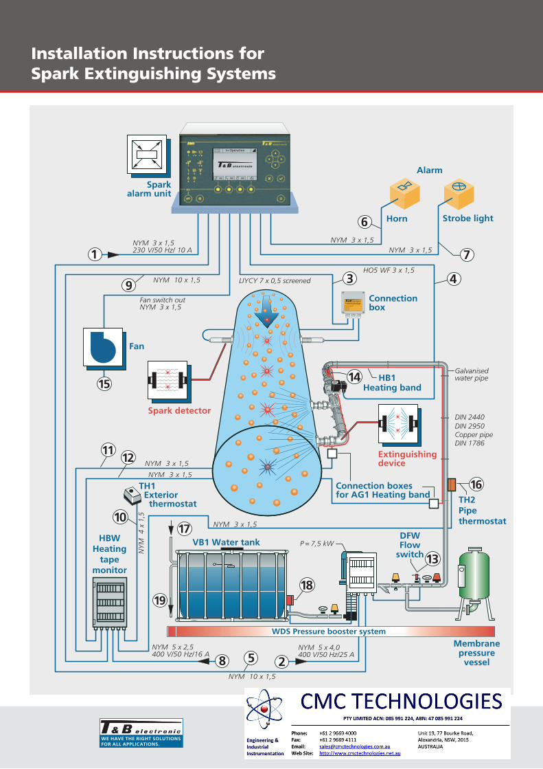
Explanation of Diagram:Installation Instructions Spark Extinguishing Systems
The diagram shown depicts a standard spark extinguishing system for monitoring a suction line.
1. Electric supply cable to the spark detec-tion centre 230/50 Hz fused with 10 A.It may not be possible to switch off theelectric circuit and no other loads may beconnected. The fuse in the main distribu-tion must be identified and labelled in“red”.Cable type and cross section:NYM 3 x 1.5 mm2
2. Electric supply cable to the pressurebooster WDS 3 x 400 V/50 Hz fused with25 A. No other loads should be connectedto this electric circuit. The fuse in the maindistribution must be identified and labelledin “red”.Cable type and cross section:NYM 5 x 4.0 mm2
3. Electric supply cable to the spark detec-tors.The spark detectors are provided withconnectors, which are plugged in at theterminal box.The connection from the terminal box tothe spark detection centre is established bymeans of a multi-core shielded cable.The terminal box must be installed in aneasily accessible position and must beprotected against moisture.Cable type and cross section:LIYCY 7 x 0.5 mm2
4. Electric supply cable to the extinguish-ing system.The solenoid valve of the extinguish-ing system is provided with a connector.The connection should be established bymeans of a flexible cable as the space inthe cable connector interior is restricted.Cable type and cross section:HO5 WF 3 x 1.5 mm2
5. Electric interlock between spark detec-tion centre and pressure booster WDS.Cable type and cross section:NYM 10 x 1.5 mm2
6. Electric supply cable to the horn H4(24 V DC).Cable type and cross section:NYM 3 x 1.5 mm2
7. Electric supply cable to the flashlight B4(24 V DC).Cable type and cross section:NYM 3 x 1.5 mm2
8. Electric supply cable for heating stripmonitoring HBW 3 x 400 V/50 Hz fusedwith 16 A.No other loads should be connected tothis electric circuit. The fuse in the maindistribution must be identified and labelledin “red”.Cable type and cross section:NYM 5 x 2.5 mm2
9. Electric supply cable between spark de-tection centre and heating strip monitoringHBW.Cable type and cross section:NYM 10 x 1.5 mm2
10. Electric supply cable to the externalthermostat TH1.The external thermostat must be fitted inan easily accessible and wind-protectedposition.Cable type and cross section:NYM 4 x 1.5 mm2
11. Electric supply cable to the self-regulat-ing heating strip HB1.Cable type and cross section:NYM 3 x 1.5 mm2
The connection is made via the terminalboxes AG1.
12. Electric supply cable for the feedbacksignal of the self-regulating heating stripHB1.Cable type and cross section:NYM 3 x 1.5 mm2
The connection is made via the terminalboxes AG1.
13. Electric supply cable to the flow moni-tor DFW. If no pressure booster is avail-able, a cable to the spark detection centremust be installed.Cable type and cross section:NYM 3 x 1.5 mm2
The flow monitor is by default wired withthe pressure booster in the terminal box ofthe WDS.
14. A gate valve R=1ì is installed upstreamof the extinguishing system. The gate valvemust be secured against unintentionalclosing.
15. Electric supply cable for the interlockbetween spark detection centre and thefans to be switched off or other externalswitchgear.Cable type and cross section:NYM 3 x 1.5 mm2 per area to be moni-tored.
16. Electric supply cable to the pipe con-tact thermostatCable type and cross section:NYM 3 x 1.5 mm2
17. Storage tank for feeding the pressurebooster.The supply cable should have a cross sec-tion of min. R=1/2ì. The level of the stor-age tank is controlled via a built-in floatingswitch. The storage tank simultaneouslyserves to biologically separate extinguish-ing water and mains water.
18. Dry-running protection for the pres-sure boosterCable type and cross section:NYM 3 x 1.5 mm2
19. Overflow storage tank: A drain towhich the overflow could be connectedshould be available.
we HAve THe rIGHT soluTIonsFor All ApplIcATIons.
Fire protection for silosPossible applications
2 <<1
3 << =
Esc
F1 F2
1 2 3
4 5 6
7 8 9
0
Linie 1
Linie 2
Linie 3
BM4-3
+-
T & B electr. Funkenmeldezentrale BM 4-314:40:52
27.04.99 13.35 UhrFeuer 1 Linie 2
Glowing particles
A
Extinguishingdevice
B
C
Spark alarm unit
Sparkdetector
By-pass smoke detector
Extinguishingdevice
silo fires!
Avoid
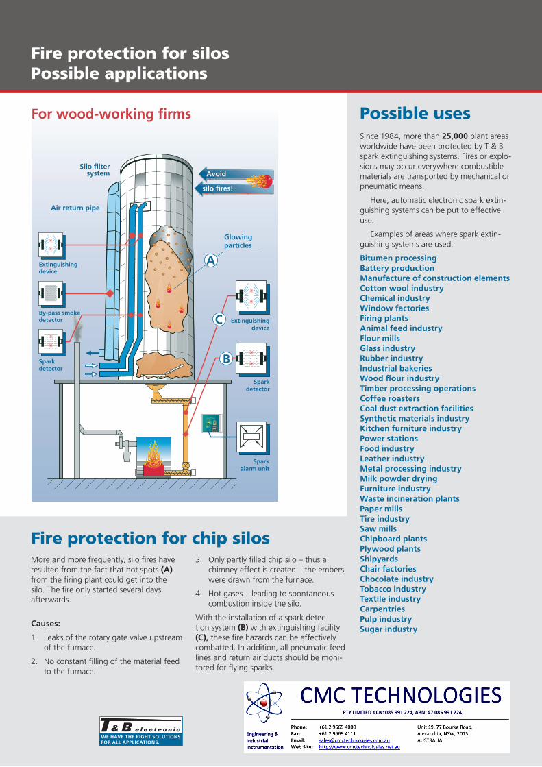
For wood-working firms
Silo filtersystem
Air return pipe
Sparkdetector
Fire protection for chip silosMore and more frequently, silo fires have resulted from the fact that hot spots (A) from the firing plant could get into the silo. The fire only started several days afterwards.
causes:
1. Leaks of the rotary gate valve upstreamof the furnace.
2. No constant filling of the material feedto the furnace.
3. Only partly filled chip silo – thus achimney effect is created – the emberswere drawn from the furnace.
4. Hot gases – leading to spontaneouscombustion inside the silo.
With the installation of a spark detec-tion system (B) with extinguishing facility (c), these fire hazards can be effectively combatted. In addition, all pneumatic feed lines and return air ducts should be moni-tored for flying sparks.
Possible usesSince 1984, more than 25,000 plant areas worldwide have been protected by T & B spark extinguishing systems. Fires or explo-sions may occur everywhere combustible materials are transported by mechanical or pneumatic means.
Here, automatic electronic spark extin-guishing systems can be put to effective use.
Examples of areas where spark extin-guishing systems are used:
Bitumen processingBattery productionManufacture of construction elementscotton wool industrychemical industrywindow factoriesFiring plantsAnimal feed industryFlour millsGlass industryrubber industryIndustrial bakerieswood flour industryTimber processing operationscoffee roasterscoal dust extraction facilitiessynthetic materials industryKitchen furniture industrypower stationsFood industryleather industryMetal processing industryMilk powder dryingFurniture industrywaste incineration plantspaper millsTire industrysaw millschipboard plantsplywood plantsshipyardschair factorieschocolate industryTobacco industryTextile industrycarpentriespulp industrysugar industry