detection of vibrations defects in gas …
TRANSCRIPT
Int. J. of Applied Mechanics and Engineering, 2020, vol.25, No.4, pp.42-58 DOI: 10.2478/ijame-2020-0048
DETECTION OF VIBRATIONS DEFECTS IN GAS TRANSPORTATION PLANT BASED ON INPUT / OUTPUT DATA ANALYSIS: GAS TURBINE
INVESTIGATIONS
B. DJAIDIR and A. HAFAIFA* Applied Automation and Industrial Diagnostics Laboratory Faculty of Science and Technology, University of Djelfa
17000 DZ, ALGERIA Gas Turbine Joint Research Team, University of Djelfa
17000 DZ, ALGERIA E-mails: [email protected]; [email protected]
M. GUEMANA
Gas Turbine Joint Research Team, University of Djelfa 17000 DZ, ALGERIA
E-mail: [email protected]
A KOUZOU Applied Automation and Industrial Diagnostics Laboratory Faculty of Science and Technology, University of Djelfa
17000 DZ, ALGERIA E-mail: [email protected]
In oil and gas industrial production and transportation plants, gas turbines are considered to be the major pieces of equipment exposed to several unstable phenomena presenting a serious danger to their proper operation and to their exploitation. The main objective of this work is to improve the competitiveness performance of this type of equipment by analyses and control of the dynamic behaviors and to develop a fault monitoring system for the equipment exposed and subject to certain eventual anomalies related to the main components, namely the shaft and the rotors. This study will allow the detection and localization of vibration phenomena in the studied gas turbine based on the input / output data.
Key words: vibrations detection, vibrations control, gas turbines, unstable phenomena, supervision system.
1. Introduction Gas turbines are used in many industrial applications; especially, they are widely used in the oil industry to ensure gas transportation in long gas pipelines. These machines are subject to several instability parameters that may directly affect their performance [1-5]. Indeed, several theoretical and industrial research studies have been carried out to improve the performance of these machines based on the elaboration of mathematical models that nearly represent the real state behavior of these machines [6-9]. The main objective of this work is to propose a gas turbine failure prediction method in real time using experimental tests based on vibration analysis for the detection of the system dysfunction to ensure an optimal operation availability of the studied gas turbine. In this context, the spectral signal analysis techniques are used to obtain the defects modeling, where the main aim is to obtain exploitable models under * To whom correspondence should be addressed
Detection of vibrations defects in gas transportation ... 43
a number of simplifying assumptions that are based on the operating parameters of the studied gas turbine. The rotor dynamics is also studied to ensure permanent monitoring and surveillance of gas turbines and to improve the safety and the performance of this system. The tests use the wavelet transform method to obtain the measured vibration signal on the turbine, and to perform a systematic analysis of the presented vibratory images of all susceptible defects that can occur in the turbine under consideration. However, the interest in the spectral analysis approach in the engineering of rotating machinery monitoring relies on the ability of these techniques to adapt to the type of gas turbine equipment, to detect their vibrations, with sufficient data in quantity and quality, using the concept of feedback in order to ensure good performance of the diagnostic task in ensuring the proper operation of the gas turbine system. Indeed, vibration analysis occupies a prominent place in the fault diagnosis of gas turbines. The approach proposed in this work combined with wavelet processing technology allows the acquisition of vibration information in real time, in order to extract useful information on the recognition of states of operation of the industrial system. In the case of vibration failures, control can be put in place to address this, detection and monitoring can be based on spectral analysis of the data quantities by vibratory signatures relating to defects with automated detection from these spectral signatures. This study allows the analysis of the vibration dynamic behavior of a gas turbine prototype which includes two shafts: a high pressure (HP) shaft and a low pressure (LP) shaft. The experimental prototype was built in order to perform the performance tests of the defects detection and to follow certain anomalies. It can be said that the use of the proposed wavelet transform approach with the spectrum analysis allows developing and reproducing all the main rotor dynamics phenomena of the studied turbine that are proved by positive validation tests. 2. Gas turbine modeling Gas turbines are complex rotating machines, composed of various fixed and moving elements [10-11]. For disc modeling, it is essential to represent the ax-symmetric rigid elements whose characteristics are given by their masses m , their polar inertia PI around the rotation axis y and their diametric inertia dI of the right section. Hence, the kinetic energy of the disc can be written in the following form [7, 12]
2 2 2 2 2disc d p
1T m u w I I 2
2 . (2.1)
Similarly, for modeling of the shaft the kinetic energy of the shaft shaftT is expressed by an
integration over the length L , where shaftU is the potential energy and shaftF is the dissipation function [13]
θ +ψL L L
2 2 2 2 2dshaft p p
0 0 à
S IT u w dy dy 2 I dy I L
2 2
, (2.2)
and the shaft potential energy is
2 2L
dshaft
0
EIU dy
2 y y
, (2.3)
with the shaft dissipation function shaftF
44 B.Djaidir, A.Hafaifa, M.Guemana and A.Kouzou
2 2L L
d dshaft
0 0
E I E IF dy dy
2 y y 2 y dy
(2.4)
where is the shaft density, E is the Young modulus, L is the length of the shaft, S is the area of the shaft
section, dI is the diametrical inertia of the shaft right section and is the damping coefficient. In general, the bearings induce external forces acting on the shaft, the energy contribution of the bearings is expressed in terms of distortion energy bearingU which is associated with their stiffness and in
terms of the dissipation function bearingF which is associated with their damping characteristics as follows
[6, 9, 13]
,2 2
bearing xx 1 2 zz 1 2
2 2bearing xx 1 2 zz 1 2
1U k u u k w w
2
1F c u u c w w
2
(2.5)
where 11
1
uu
w
is the displacement at the center of the rotor and 22
2
uu
w
is the displacement of the
stator. The obtained data are analyzed by using mathematical models for the structural member of the rotor system. In order to obtain a mathematical model for vibration analysis of the gas turbine plant, modeling parameters are selected; the mass of the shaft M with a stiffness K and damping coefficient C rotating with a speed subjected to an excitation force sin0F F t . The equation of motion can be written as follows
sin ,
sin
0
0
M x Cx K x F t
C K Fx x x t
M M M
(2.6)
where , ,x x x are the displacement and their derivatives (velocity and acceleration). The motion equation is a linear homogeneous second order differential equation. The solution of this equation consists of two parts p cx x x . The solution can then be presented by two separated expressions
as follows
sin cos ,
sin ( ).
p 1 2
atc d
x A t A t
x B e
(2.7)
Thus, the velocity and acceleration can be presented as
cos sin ,
sin cos .
1 2
2 21 2
x A t A t
x A t A t
(2.8)

Detection of vibrations defects in gas transportation ... 45
Substituting Eqs (2.7) and (2.8) into Eqs (2.6), the following equation is obtained
sin cos cos sin sin21 2 1 2 0K M A t A t C A t A t F t . (2.9)
A comparison of the coefficients sinωt and cos t , on the left and the right-hand side, gives separately the following algebraic expressions
,21 2 0
22 1
K M A C A F
K M A C A 0
(2.10)
where 2nK
M
is the rigidity with 0
0F
XK
, c n
C C
C 2 M
is the damping ratio where c nC 2M is
the critical damping coefficient. The forced vibration amplitude is given by
02
22
FX
K M C
. (2.11)
Thus, the excitation force is
22 2
0C M
F KX 1K K
, (2.12)
or it can be expressed as follows
2 22
0 2nn
F KX 1 2
. (2.13)
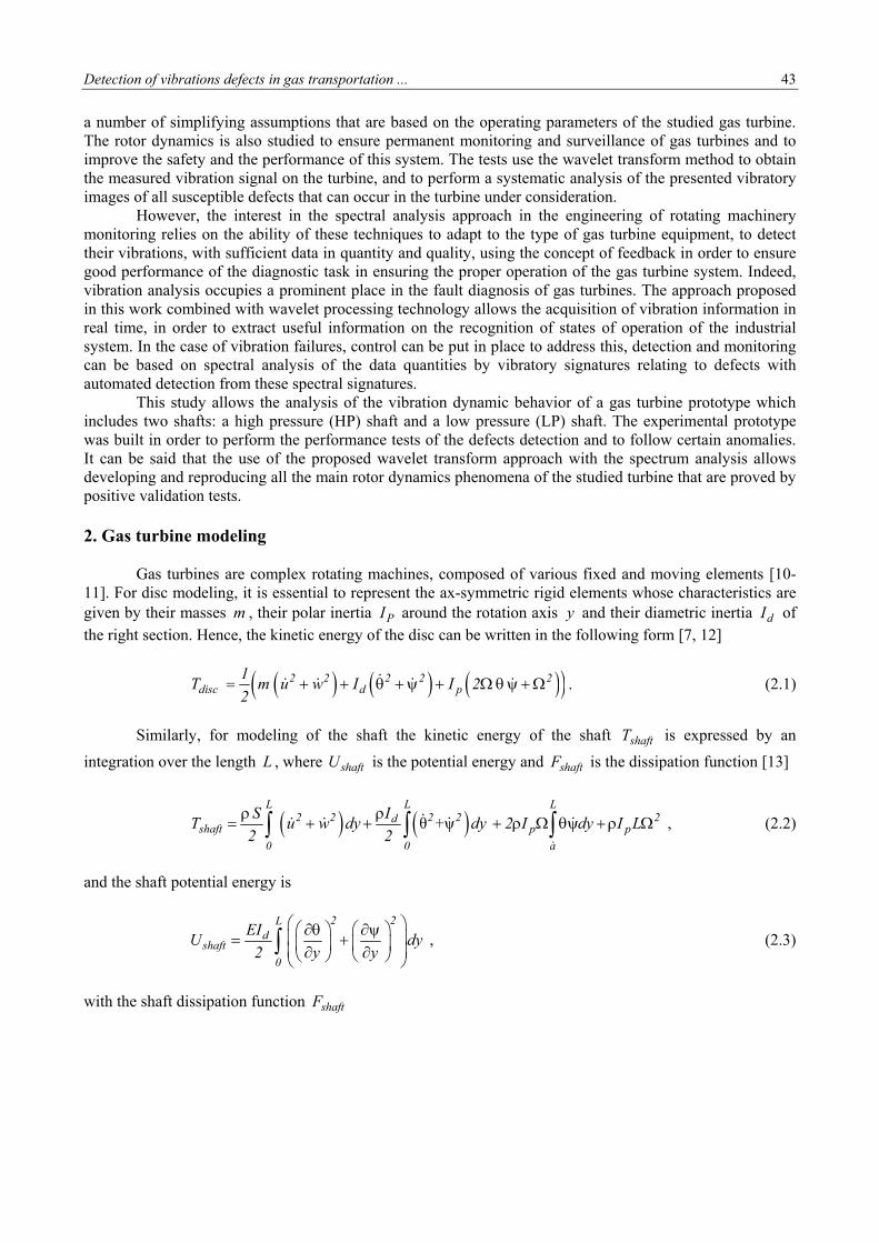
The current developments in production systems of gas transportation through gas turbine plants lead to launching new monitoring projects [14-18]. The vibration monitoring in a gas turbine is a very effective technique which is widely used in various industrials applications. Therefore, it is of great importance in the predictive maintenance framework for most installations using this type of equipment due to its ability to deal with the imprecise information. It allows good monitoring of various parameters in the gas turbine by ensuring a continued optimum exploitation of this system. In this work, the measurements were obtained from the rotors of the studied gas turbine MS -3002 TC-201, which is installed at the gas compression station SC1 TIMZHERT, south of Hassi R'MEL in Algeria. In this gas compression station, there are: four turbochargers GZ1 units, three units of turbochargers GZ2 and four units of turbochargers GZ3. The MS-3002 TC-201 turbine is composed of two rotors that are mechanically independent rotating at nominal speeds of 7100 RPM and of 6500 RPM, respectively. The first rotor has an axial compressor (with 15 stages of compression) and two shafts in the HP turbine. The axial compressor is shown in Fig.1. It compresses the air to be sent to the combustion chamber and the HP turbine. The other rotor given by the LP
46 B.Djaidir, A.Hafaifa, M.Guemana and A.Kouzou
shaft drives the centrifugal compressor by a mechanical coupling. The turbine is provided with annular combustors and burners with supplied fuel gas, the speed parameters are given in Tab.1. The high temperature exhaust gas under pressure flows through the nozzles of the first stage, then the HP nozzles flows by the LP turbine.
Bearing p1
Compressor axial
(15 stages)
Fig.1. Axial compressor of the examined GE MS 3002 turbine.
Table 1. Turbine speed parameters.
Wheel HP Wheel LP
Nominal speed 7100 RPM 6500 RPM
Speed threshold TNH /TNL 95.2 % 6825 RPM 105 % 6725 RPM
Over speed protection 107.9% 7660 RPM 112.9% 7338 RPM TNL is the turbine LP shaft speed input and TNH is the turbine HP shaft speed input
In practical situations, several rotating elements of the turbine produce vibrations, when they are partially or completely degraded [19-21]. The present work proposes the development of a modeling approach for the supervision and diagnosis of the fundamental elements in the studied gas turbine. Taking a bearing as an example, the next subsection presents analytical modeling of hydrodynamic bearings defects to simulate and localize the vibration behavior caused by the presence of failures at the bearing. The on-site signals acquisition allows obtaining information and the impact of the periodical phenomenon which is occurring at a characteristic frequency of the defect. Whenever this phenomenon occurs, it generates a vibration at the resonance frequency. 2.1. Hydrodynamic bearings defects The rotor unbalance is characterized mainly by an unequal mass distribution within a circular plan, e.g. in a disk. This unbalance mass distribution is due to several mechanical and construction circumstances that can occur progressively during the normal operation of rotary machines. For the modeling of this phenomena, it is supposed that the unbalance is presented by an additional punctual mass bm which is estimated as a discrete unbalance at an arbitrary location within the circular plan of the disk. It is important to notice that the rotor of a gas turbine has several healthy disks within parallel plans that are supposed initially to be normal to the shaft axis yO of a rotating frame R compared to the ground stationary frame

Detection of vibrations defects in gas transportation ... 47
gR . For the modeling of the unbalance the simplified configuration of a turbine disk, the kinetic energy bT of the discrete unbalance under this case can be expressed as follows [22-24]
s
b
2Rb
b Pm
T2
v . (2.14)
The coordinates of the mass unbalance with respect to the ground frame gR are projected into R frame as follows
sin ( ) sin ( )
cos( ) cos( )
o b b b o b b bg g
p b o b o b
o b b b o b b bR R R
x x r t x x r t
O P O O OP y y y y
z z r t z z r t
. (2.15)
Based on the formula of the composed derivative given by Qing He et al. on [21], the speed of the
mass unbalance with respect to the fixed coordinate system gR (absolute velocity) can be expressed in R as follows [17, 24]
ggg
b
R Rg g RR gb b
RP pdO P dO P
w O Pdt dt
v
(2.16)
where g
x
R yR
z
w
w
w
w .
As the value of the coordinate py following the axis yO is considered constant and time
independent compared to the ground frame, its femoral derivative within the frame R is null
cos( ) sin ( )
cos( ) cos( )
g
b
x0 b b b o b b b
R yP 0 o b
z0 b b b o b b bR R
R
wx x r t x x r t
y w y y
z z r t z z r tw
v
. (2.17)
This leads to the following expression
cos( ) cos( ) ( )
cos( ) sin( )
sin( ) ( ) sin( )
g
b
y zb 0 b b o b b b b o
Rx zP
0 o b b b o b b b
x yb 0 b b b o o b b b R
x x r t z z r t w y y w
y z z r t w x x r t w
z z r t y y w x x r t w
v
. (2.18)
Replacing the vector g
b
RPv in Eq.(2.14) by its components presented in Eq.(2.18), the following
expression is obtained
48 B.Djaidir, A.Hafaifa, M.Guemana and A.Kouzou
( cos( )) cos( ) ( )
cos( ) sin( )
sin( ) ( ) sin( ) .
2y zbb b 0 b b o b b b b o
2x z0 o b b b o b b b
2x yb 0 b b b o o b b b
mT x x r t z z r t w y y w
2
y z z r t w x x r t w
w z r t y y w x x r t w
(2.19)
Equation (2.19) can be rewritten as follows
2( , ) ( ) ( cos ( ) sin( ) )
(( ( ) ( ) ) ( ) cos( )+
( ( ) ( ) )( cos( ) sin ( ))
( ( ) ( ) )(
2y 2 x zb b b
b 1 b b b
y z yb b 0 b b o b o b
x z x z0 b o o b b b
x y y0 b b o o b
m m rT t y t w w t w t
2 2
m r x x w z w y y w w t
y z z w x x w w t w t
z z y y w x x w w
)sin ( )).bt
(2.20)
The term 2( ) ( cos ( ) sin( ) )2
y 2 x zb bb b
m rw w t w t
2 is not a function of bx and bz .
Therefore, it has no contribution to the variation of bT . The final expression of the kinetic energy bT can be expressed as follows
(( ( ) ( ) ) ( )cos( )+
( ( ) ( ) )( cos( ) sin ( ))
( ( ) ( ) )( )sin ( )).
y z yb b b 0 b b o b o b
x z x z0 b o o b b b
x y y0 b b o o b b
T m r x x z z w y y w w t
y z z w x x w w t w t
z z y y w x x w w t
(2.21)
For misalignment (radial and angular), the axes of the two rotors present an angular misalignment at the coupling level, or a radial misalignment (concentricity defect) or the combination of both kinds of misalignment. The degradation phenomena modeling is based primarily on the parameters of the process to represent the main dynamic characteristics of the rotor excitation process. In this section, the typical vibration signals and their associated defects have been modeled to represent the dynamic behavior as a function of different fixed and moving elements in the examined turbine system. 3. Gas turbine rotor alignment modelling results The use of an accelerometer on the gas turbine for detecting the defects of misalignment is very important. Each sensor must be placed at specific points of measurement in the examined system. Indeed, unbalance failure is a mechanical phenomenon, especially vibration phenomenon, which leads to development of specific signatures that can be detected using different signal processing techniques. A preliminary reading of the operating parameters of the studied turbine was made; the misalignment at the load side is detected during the machine loading at 89% of the LP speed and at 97% of the HP speed. A vibratory signal of the axial and radial displacement of the rotor parts has been produced, using a selector switch on the studied turbine and on the centrifugal compressor. The parameters are defined and this monitoring system made it possible to collect periodically the measurement with check values to pre-defined thresholds and following the evolution over time of the values achieved for each of them (historical evolution). Also, this system allowed interpreting the exceeding evolution and threshold violations (development diagnosis) and analyzing the spectra with the time signals acquired to refine or confirm the diagnosis.
Detection of vibrations defects in gas transportation ... 49
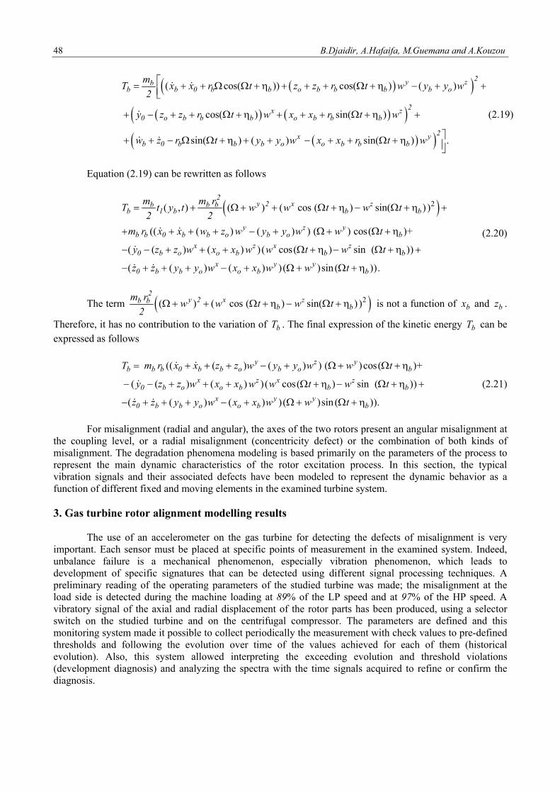
Practically, the reduction of the above problems requires the right solutions. For this reason it has been necessary to change the coupling of the auxiliary side, with an inspection of the gear housing of this auxiliary side and to make a dynamic balancing with a change of cooling exchangers to remove the unbalance effects. A significant wear at the bearing 4 in the rotor of the examined turbine on the side of the centrifugal compressor is observed. It is characterized by a depth and width of the order of 1 mm as shown clearly in Fig.2. These traces are most probably due to the friction of the shaft with one or more of the other components such as the ring or the gall, whereas the dimension of the wear depends on the degree of the friction effect. The rotor was under stress during operation of the compressor before the overhaul. The misalignment could instigate tensions. The mechanical force is transmitted by the coupled shafts that are required to be aligned. Otherwise, significant vibration which is related to the type of misalignment may occur and will act on the bearings.
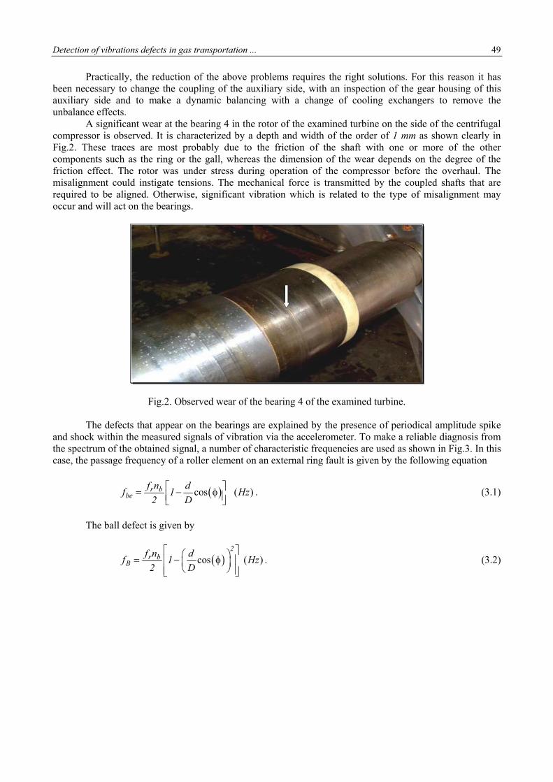
Fig.2. Observed wear of the bearing 4 of the examined turbine. The defects that appear on the bearings are explained by the presence of periodical amplitude spike and shock within the measured signals of vibration via the accelerometer. To make a reliable diagnosis from the spectrum of the obtained signal, a number of characteristic frequencies are used as shown in Fig.3. In this case, the passage frequency of a roller element on an external ring fault is given by the following equation
cos ( )r bbe
f n df 1 Hz
2 D
. (3.1)
The ball defect is given by
cos ( )2
r bB
f n df 1 Hz
2 D
. (3.2)
50 B.Djaidir, A.Hafaifa, M.Guemana and A.Kouzou
0 500 1000 1500 2000 2500 3000 3500 4000 4500 5000
-2
-1
0
1
2
Frequency Hz
Am
plitu
de
(µm
)
Shock periodic
Fig.3. Signal frequency fault at the inner ring.
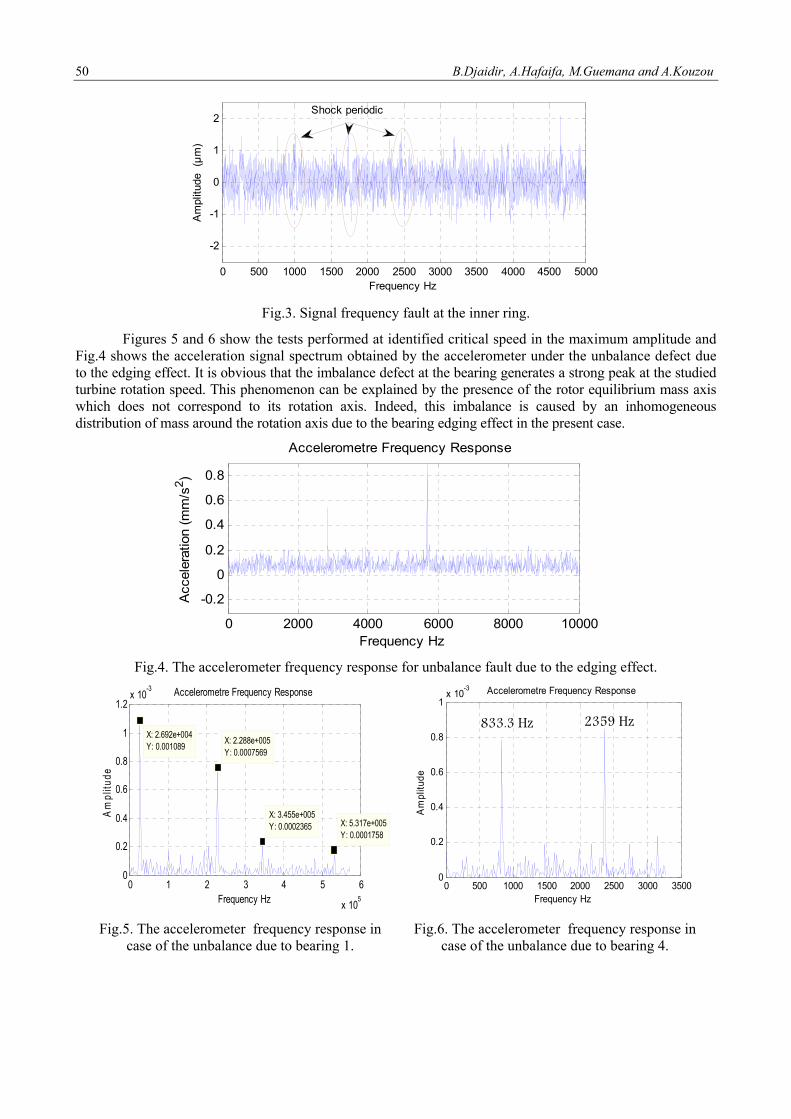
Figures 5 and 6 show the tests performed at identified critical speed in the maximum amplitude and Fig.4 shows the acceleration signal spectrum obtained by the accelerometer under the unbalance defect due to the edging effect. It is obvious that the imbalance defect at the bearing generates a strong peak at the studied turbine rotation speed. This phenomenon can be explained by the presence of the rotor equilibrium mass axis which does not correspond to its rotation axis. Indeed, this imbalance is caused by an inhomogeneous distribution of mass around the rotation axis due to the bearing edging effect in the present case.
0 2000 4000 6000 8000 10000
-0.2
0
0.2
0.4
0.6
0.8
Accelerometre Frequency Response
Frequency Hz
Acc
eler
atio
n (m
m/s
2 )
Fig.4. The accelerometer frequency response for unbalance fault due to the edging effect.
0 1 2 3 4 5 6
x 105
0
0.2
0.4
0.6
0.8
1
1.2x 10
-3
X: 5.317e+005Y: 0.0001758
Frequency Hz
Am
plitu
de
Accelerometre Frequency Response
X: 3.455e+005Y: 0.0002365
X: 2.288e+005Y: 0.0007569
X: 2.692e+004Y: 0.001089
0 500 1000 1500 2000 2500 3000 35000
0.2
0.4
0.6
0.8
1x 10
-3
Frequency Hz
Am
plitu
de
Accelerometre Frequency Response
2359 Hz833.3 Hz
Fig.5. The accelerometer frequency response in case of the unbalance due to bearing 1.
Fig.6. The accelerometer frequency response in case of the unbalance due to bearing 4.
Detection of vibrations defects in gas transportation ... 51
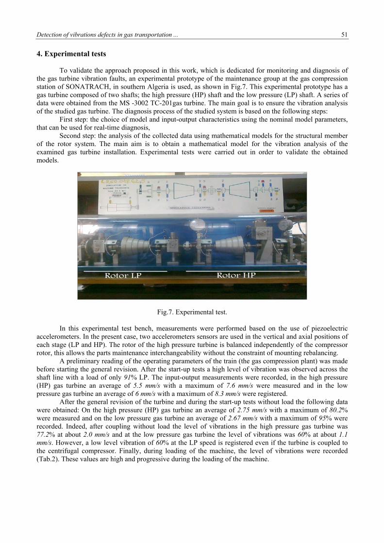
4. Experimental tests To validate the approach proposed in this work, which is dedicated for monitoring and diagnosis of the gas turbine vibration faults, an experimental prototype of the maintenance group at the gas compression station of SONATRACH, in southern Algeria is used, as shown in Fig.7. This experimental prototype has a gas turbine composed of two shafts; the high pressure (HP) shaft and the low pressure (LP) shaft. A series of data were obtained from the MS -3002 TC-201gas turbine. The main goal is to ensure the vibration analysis of the studied gas turbine. The diagnosis process of the studied system is based on the following steps: First step: the choice of model and input-output characteristics using the nominal model parameters, that can be used for real-time diagnosis, Second step: the analysis of the collected data using mathematical models for the structural member of the rotor system. The main aim is to obtain a mathematical model for the vibration analysis of the examined gas turbine installation. Experimental tests were carried out in order to validate the obtained models.
Fig.7. Experimental test.
In this experimental test bench, measurements were performed based on the use of piezoelectric accelerometers. In the present case, two accelerometers sensors are used in the vertical and axial positions of each stage (LP and HP). The rotor of the high pressure turbine is balanced independently of the compressor rotor, this allows the parts maintenance interchangeability without the constraint of mounting rebalancing. A preliminary reading of the operating parameters of the train (the gas compression plant) was made before starting the general revision. After the start-up tests a high level of vibration was observed across the shaft line with a load of only 91% LP. The input-output measurements were recorded, in the high pressure (HP) gas turbine an average of 5.5 mm/s with a maximum of 7.6 mm/s were measured and in the low pressure gas turbine an average of 6 mm/s with a maximum of 8.3 mm/s were registered. After the general revision of the turbine and during the start-up tests without load the following data were obtained: On the high pressure (HP) gas turbine an average of 2.75 mm/s with a maximum of 80.2% were measured and on the low pressure gas turbine an average of 2.67 mm/s with a maximum of 95% were recorded. Indeed, after coupling without load the level of vibrations in the high pressure gas turbine was 77.2% at about 2.0 mm/s and at the low pressure gas turbine the level of vibrations was 60% at about 1.1 mm/s. However, a low level vibration of 60% at the LP speed is registered even if the turbine is coupled to the centrifugal compressor. Finally, during loading of the machine, the level of vibrations were recorded (Tab.2). These values are high and progressive during the loading of the machine.
52 B.Djaidir, A.Hafaifa, M.Guemana and A.Kouzou
Table 2. Recorded vibrations.
HP 99% LP100% HP 99% LP 95.5% 7,5mm/s 5,8 mm/s 7,2mm/s 5,18 mm/s
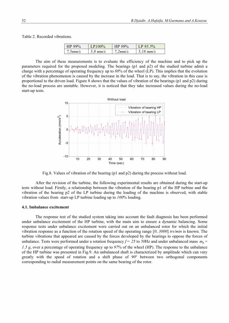
The aim of these measurements is to evaluate the efficiency of the machine and to pick up the parameters required for the proposed modeling. The bearings (p1 and p2) of the studied turbine admit a charge with a percentage of operating frequency up to 88% of the wheel (LP). This implies that the evolution of the vibration phenomenon is caused by the increase in the load. That is to say, the vibration in this case is proportional to the driven load. Figure 8 shows that the values of vibration of the bearings (p1 and p2) during the no-load process are unstable. However, it is noticed that they take increased values during the no-load start-up tests.
10 20 30 40 50 60 70 80 90-10
-5
0
5
10
Time (sec)
Acc
eler
atio
n (m
m/s
2 )
Without load
Vibration of bearing HP
Vibration of bearing LP
Fig.8. Values of vibration of the bearing (p1 and p2) during the process without load.
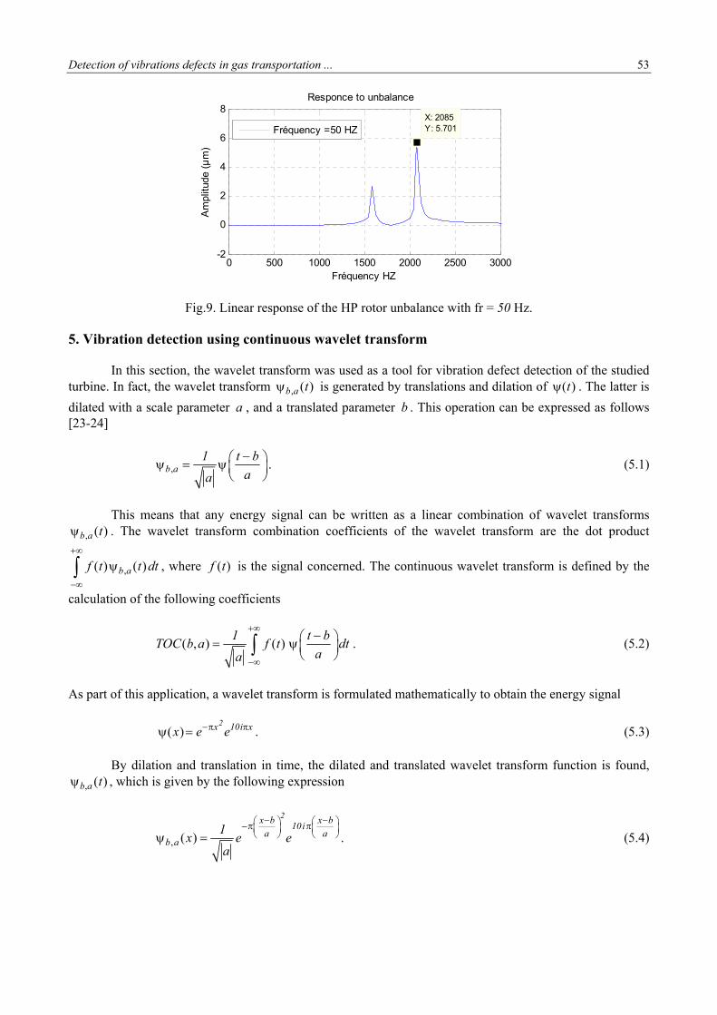
After the revision of the turbine, the following experimental results are obtained during the start-up tests without load. Firstly, a relationship between the vibration of the bearing p1 of the HP turbine and the vibration of the bearing p2 of the LP turbine during the loading of the machine is observed, with stable vibration values from start-up LP turbine loading up to 100% loading. 4.1. Imbalance excitement The response test of the studied system taking into account the fault diagnosis has been performed under unbalance excitement of the HP turbine, with the main aim to ensure a dynamic balancing. Some response tests under unbalance excitement were carried out on an unbalanced rotor for which the initial vibration response as a function of the rotation speed of the operating range [0; 3000] trs/min is known. The turbine vibrations that appeared are caused by the forces developed by the bearings to oppose the forces of unbalance. Tests were performed under a rotation frequency f = 25 to 50Hz and under unbalanced mass bm = 1.5 g, over a percentage of operating frequency up to 97% of the wheel (HP). The response to the unbalance of the HP turbine was presented in Fig.9. An unbalanced shaft is characterized by amplitude which can vary greatly with the speed of rotation and a shift phase of 90° between two orthogonal components corresponding to radial measurement points on the same bearing of the rotor.
Detection of vibrations defects in gas transportation ... 53
0 500 1000 1500 2000 2500 3000-2
0
2
4
6
8
X: 2085Y: 5.701
Fréquency HZ
Am
plitu
de (
µm
)
Responce to unbalance
Fréquency =50 HZ
Fig.9. Linear response of the HP rotor unbalance with fr = 50 Hz.
5. Vibration detection using continuous wavelet transform In this section, the wavelet transform was used as a tool for vibration defect detection of the studied turbine. In fact, the wavelet transform , ( )b a t is generated by translations and dilation of ( )t . The latter is
dilated with a scale parameter a , and a translated parameter b . This operation can be expressed as follows [23-24]
,b a1 t b
aa
. (5.1)
This means that any energy signal can be written as a linear combination of wavelet transforms
, ( )b a t . The wavelet transform combination coefficients of the wavelet transform are the dot product
,( ) ( )b af t t dt
, where ( )f t is the signal concerned. The continuous wavelet transform is defined by the
calculation of the following coefficients
( , ) ( )1 t b
TOC b a f t dtaa
. (5.2)
As part of this application, a wavelet transform is formulated mathematically to obtain the energy signal
( )2x 10i xx e e . (5.3)
By dilation and translation in time, the dilated and translated wavelet transform function is found,
, ( )b a t , which is given by the following expression
, ( )
2x b x b10i
a ab a
1x e e
a
. (5.4)
54 B.Djaidir, A.Hafaifa, M.Guemana and A.Kouzou
5.1. Inverse wavelet transform To reconstruct the original signal from its wavelet transform coefficients, the source wavelet transform must necessarily satisfy the following condition [24]
( )
2
0
fC df
f
. (5.5)
If the condition of Eq.(5.5) is satisfied, the following expression can be obtained
( ) ( , )2
0
1x t a X a b da db
C
. (5.6)
It may be noted that to verify the condition of eligibility we must necessarily have ( )f 0 . It
implies that ( )t dt 0
. Note that this condition is "almost" sufficient and in practice is used quite often
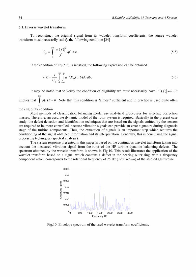
the eligibility condition. Most methods of classification balancing model use analytical procedures for selecting correction masses. Therefore, an accurate dynamic model of the rotor system is required. Basically in the present case study, the defect detection and identification techniques that are based on the signals emitted by the sensors are required to be more controlled, because vibration signals can provide an error signature during diagnosis stage of the turbine components. Thus, the extraction of signals is an important step which requires the conditioning of the signal obtained information and its interpretation. Generally, this is done using the signal processing techniques (spectral analysis). The system response presented in this paper is based on the continuous wavelet transform taking into account the measured vibration signal from the rotor of the HP turbine dynamic balancing defects. The spectrum obtained by the wavelet transform is shown in Fig.10. This result illustrates the application of the wavelet transform based on a signal which contains a defect in the bearing outer ring, with a frequency component which corresponds to the rotational frequency of 25 Hz (1200 tr/min) of the studied gas turbine.
0 500 1000 1500 2000 2500 30000
0.005
0.01
0.015
0.02
0.025
0.03
0.035
Frequency HZ
Am
plitu
de
(µm
)
Fig.10. Envelope spectrum of the used wavelet transform coefficients.

Detection of vibrations defects in gas transportation ... 55
For a ball bearing containing bn number of balls, rotating at the frequency rf (shaft rotation frequency), a default score creates a punctual shock between the different rotating elements whose frequencies are defined as follows
cosr bbi
f n df 1
2 D
. (5.7)
This equation represents the passage frequency of a rotating element on an inner ring defect with a signal modulation by the frequency cf . Equation (5.7) becomes
.cos2
r bB c
f n df 1 f
2 D
(5.8)
where D is the diameter of the center of the balls, d is the diameter of the ball and is the contact angle between the ball and the raceway. To investigate the relevance of the selected wavelet transform parameters, an automatic fault classification was achieved based on the collected signals from bearing 1 and bearing 2 separately, where a default edging was modelled at these bearings. The classification was packaged for the retail vectors of the used wavelet transform. The variations in multi-level decomposition of the used wavelet transform are used to give a real image of each defect in the studied system. This approach makes it possible to compare the performance of the proposed wavelet transform method based on vibration control strategy, taking into consideration the types of the detected faults. The use of vibratory action is to aid the diagnosis of condition of rotating machines, the vibration analyzers, to determine the frequency decomposition of the vibrational signal, for detecting vibrations of the gas turbine considered. This technique offers a very fine analysis of the signals and diagnoses defects of various kinds, and in several configurations. Using the discrete wavelet transform approach, the studied gas turbine system allows a quick access to information. The model developed in this work deals with the dynamic behavior of the gas turbine rotor (MS -3002 TC-201) rotating at high speed and which is supported by bearings that are subject to the unbalance and misalignment defects. It is found that that the studied system has certain instability areas, that are varying with the frequency of rotor speed rotation and the degree of unbalance. The obtained experimental results allow validation of the proposed approach. These results confirm clearly that the bearing lifespan depends on the load acting on the shaft and on the shaft rotation speed, and the nature and quality of the force action points at the bearings. The spectral structure in the presence of an inner ring bearing defect is shown. The appearance of these structural defects on the HP turbine rotor shaft is a function of the bearing defect. This can be explained by the presence of oscillations in the torque load. These fluctuations tend to occur at the same characteristic frequency of the defect. From the obtained results, it can be concluded that the proposed approach is effective in the detection and localization of defects caused by vibrations in gas turbine systems. The approach allows the vibration prediction of the examined turbine. It is clear that the performance characteristics of these systems can be ensured with certain risk of error. Moreover, the experiments carried out in this work have confirmed the effectiveness of the proposed approach to ensure prevention of random nature residual failures. 6. Conclusion Monitoring and surveillance of the gas turbine vibrations play an important role in improving the safety of gas compression systems. Indeed, mastering the vibration problems faced in real industrial plants of rotating equipment increases the performance of these facilities. In this work, detection and analysis of vibrations were carried out based on spectral analysis techniques to develop specific signatures using signal
56 B.Djaidir, A.Hafaifa, M.Guemana and A.Kouzou
processing techniques dedicated to fault diagnosis in rotating machines. However, this work deals with the modeling of degradation phenomena. Such modelling that allows access to the reliable diagnosis of gas turbines and allows control of their vibratory behavior. This approach is validated by the experimental procedure presented in this work, using the signal processing techniques associated with the parameterization of the position of the shaft based on the operational input / output data of this rotating machine. The use of the wavelet transform makes it possible to obtain satisfactory results of modeling the dynamic behavior of the studied gas turbine. The experimental prototype has allowed validation tests for detecting non-stationary defects in the vibratory signals of the studied machine. It has allowed as well modeling of the misalignment and bearings defects. It provides a practical interpretation of the nature of these anomalies based on the evolution of the spectral structure in the presence of these kind of defects. Acknowledgments This work is supported by the Directorate General for Scientific Research and Technological Development (DGRSDT) and was carried out at the Applied Automation and Industrial Diagnostics Laboratory and at the Gas Turbine Joint Research Team of the University of Djelfa, Algeria. Nomenclature a − scale parameter b − translated parameter C − damping coefficient cC − critical damping coefficient
D − diameter of the center of the balls d − diameter of the ball E − Young modulus
F − excitation force 0F − initial excitation force
bearing
F − dissipation function
shaftF − shaft dissipation function
f − rotation frequency Bf − ball defect frequency
bif − shock frequency
cf − passage frequency
rf − shaft rotation frequency
GT − gas turbine HP − high pressure dI − diametrical inertia
PI − polar inertia
K − stiffness coefficient K − rigidity L − shaft length LP − low pressure M − shaft mass m − masses bm − punctual mass
bn − number of balls
yO − shaft axis
R − rotating frame
Detection of vibrations defects in gas transportation ... 57
gR − ground stationary frame S − shaft section TOC − continuous wavelet transform bT − kinetic energy of the unbalance
discT − kinetic energy of the disc
shaftT − kinetic energy of the shaft
t − time
bearingU − distortion energy
shaftU − shaft potential energy
1u − center of the rotor displacement
2u − displacement of the stator.
y − rotation axis x, y, z − axis directions , ,x x x − displacement and their derivatives
− shaft density − damping coefficient
, ( )b a t − wavelet transform
− damping ratio
− contact angle
References [1] Bendjama H., Boucherit M.S., Bouhouche S. and Mansour M. (2010): Vibration signal analysis using wavelet
transform –PCA-NN technique for fault diagnosis in rotating machinery. – The Mediterranean Journal of Measurment and Control, vol.6, No.4, pp.145-154.
[2] Khadersab A. and Shivakumar S. (2010): Vibration analysis techniques for rotating machinery and its effect on bearing faults. – Procedia Manufacturing, vol.20, pp.247-252.
[3] Madhavan S., Rajeev Jain, Sujatha C. and Sekhar A.S. (2014): Vibration based damage detection of rotor blades in a gas turbine engine. – Engineering Failure Analysis, vol.46, pp.26-39.
[4] Paolo Pennacchi and Andrea Vania (2008): Diagnostics of a crack in a load coupling of a gas turbine using the machine model and the analysis of the shaft vibrations. – Mechanical Systems and Signal Processing, vol.22, No.5, pp.1157-1178.
[5] Sandeep Kumar, Niranjan Roy and Ranjan Ganguli (2007): Monitoring low cycle fatigue damage in turbine blade using vibration characteristics. – Mechanical Systems and Signal Processing, vol.21, No.1, pp.480-501.
[6] Ahmed Hafaifa, Mouloud Guemana and Attia Daoudi (2015): Vibration supervision in gas turbine based on parity space approach to increasing efficiency. – Journal of Vibration and Control, vol.21, pp.1622-1632.
[7] Goudarzi M., Vahidi B., Naghizadeh R.A., Hosseinian S.H. (2015): Improved fault location algorithm for radial distribution systems with discrete and continuous wavelet analysis. – International Journal of Electrical Power & Energy Systems, vol.67, pp.423-430.
[8] Maria Martinez-Luengo, Athanasios Kolios, Lin Wang (2016): Structural health monitoring of offshore wind turbines: A review through the Statistical Pattern Recognition Paradigm. – Renewable and Sustainable Energy Reviews, vol.64, pp.91-105.
[9] Mohamed Ben Rahmoune, Ahmed Hafaifa, Kouzou Abdellah and XiaoQi Chen (2017): Monitoring of high-speed shaft of gas turbine using artificial neural networks: Predictive model application. – DIAGNOSTYKA the Journal of Polish Society of Technical Diagnostics (PSTD), vol.18, No.4, pp.3-10.
[10] Christophe Bovet and Laurent Zamponi (2016): An approach for predicting the internal behaviour of ball bearings under high moment load. – Mechanism and Machine Theory, vol.101, pp.1-22.
58 B.Djaidir, A.Hafaifa, M.Guemana and A.Kouzou
[11] Günyaz Ablay (2013): A modeling and control approach to advanced nuclear power plants with gas turbines. – Energy Conversion and Management, vol.76, pp.899-909.
[12] Mishra R.K., Johny Thomas, Srinivasan K., Vaishakhi Nandi and Raghavendra R. Bhatt (2017): Failure analysis of an un-cooled turbine blade in an aero gas turbine engine. – Engineering Failure Analysis, vol.79, pp.836-844.
[13] ChunLin Zhang, Bing Li, Bin Qiang Chen, Hong Rui Cao, Yan Yang Zi and Zheng Jia He (2015): Weak fault signature extraction of rotating machinery using flexible analytic wavelet transform. – Mechanical Systems and Signal Processing, vol.64-65, pp.162-187.
[14] Elias Tsoutsanis, Nader Meskin, Mohieddine Benammar and Khashayar Khorasani (2016): A dynamic prognosis scheme for flexible operation of gas turbines. – Applied Energy, vol.164, pp.686-701.
[15] Mohamed Benrahmoune, Ahmed Hafaifa, Mouloud Guemana and XiaoQi Chen (2018): Detection and modeling vibrational behavior of a gas turbine based on dynamic neural networks approach. – Journal of Mechanical Engineering - Strojnícky Časopis, vol.68, No.3, pp.143-166.
[16] Pak Kin Wong, Zhixin Yang, Chi Man Vong and Jianhua Zhong (2014): Real-time fault diagnosis for gas turbine generator systems using extreme learning machine. – Neurocomputing, vol.128, pp.249-257.
[17] Qu S., Fu C.M., Dong C., Tian J.F., Zhang Z.F. (2013): Failure analysis of the 1st stage blades in gas turbine engine. –Engineering Failure Analysis, vol.32, pp.292-303.
[18] Wangpeng He, Yanyang Zi, Binqiang Chen, Feng Wu and Zhengjia He (2015): Automatic fault feature extraction of mechanical anomaly on induction motor bearing using ensemble super-wavelet transform. – Mechanical Systems and Signal Processing, vol.54-55, pp.457-480.
[19] Haidong Shao, Hongkai Jiang, Xingqiu Li and Tianchen Liang (2010): Rolling bearing fault detection using continuous deep belief network with locally linear embedding. – Computers in Industry, vol.96, pp.27-39.
[20] Lei Wang, Zhiwen Liu, Qiang Miao and Xin Zhang (2018): Time–frequency analysis based on ensemble local mean decomposition and fast kurtogram for rotating machinery fault diagnosis. – Mechanical Systems and Signal Processing, vol.103, pp.60-75.
[21] Mohammadreza Tahan, Elias Tsoutsanis, Masdi Muhammad, Abdul Karim Z.A. (2017): Performance-based health monitoring, diagnostics and prognostics for condition-based maintenance of gas turbines: A review. – Applied Energy, vol.198, pp.122-144.
[22] Nadji Hadroug , Ahmed Hafaifa, Abdellah Kouzou and Ahmed Chaibet (2020): Diagnostic of gas turbine defects using a hybrid approach based on a neuro-fuzzy system: Monitoring strategy elaboration. –International Journal of Applied Automation and Industrial Diagnostics, vol.1, No.1, pp.14-27.
[23] Sara Nasiri, Mohammad Reza Khosravani and Kerstin Weinberg (2017): Fracture mechanics and mechanical fault detection by artificial intelligence methods: A review. – Engineering Failure Analysis, vol.81, pp.270-293.
[24] Shun Li and Jin Wen (2014): A model-based fault detection and diagnostic methodology based on PCA method and wavelet transform. – Energy and Buildings, vol.68, pp.63-71.
Received: May 28, 2019
Revised: July 30, 2020