detectors for astronomy
TRANSCRIPT

Detectors for Astronomy and Astrophysics : towards a Roadmap
Colin CunninghamUK Astronomy Technology
Centre, Edinburgh

SCOPE
• Astronomy & Astrophysics• Not Solar System or Particle
Astrophysics • X-ray to submm• Space & Ground-based

Technology Planning: Roadmap
timeScience Goals
Facility, Mission or Instrument
Technology

Major Science Drivers
• Cosmology• Dark Energy, Dark Matter• Extreme Astrophysics• Star and Planet Formation• Astrobiology & Exoplanets

Origins of Galaxies and structure of the Universe
Tracing the physical origin, evolution, and large scale structure of matter and energy, from the Big Bang, to present, remains one of highest priority research areas in all of science

Key Epochs in the Early UniverseReionization in the Early Universe
Uni
vers
e Io
nize
d
Uni
vers
e N
eutr
al
Photons from this scattering surface are what we now see as the Cosmic Microwave Background (CMB)

“First Light” in a Dark Universe
Simulation of an Ultra Deep NIR Image of the First Stars
• Using current and/or next-gen telescopes, we will, for the first time, detect the first luminous objects in the universe – the “First Light”
• The light from these distant objects is red shifted to 1-2 µm, hence the need for large format, low noise, NIR detectors in the future

Planet Finding & Astrobiology• Challenge:
• All exo-planets found so far are gas giants
• Find earth-like planets• Search for bio-markers

THE PROBLEM:Speckle illustration from ESO VLT-PF study
> 1010 photons< 10 photons

A solution: Differential Imaging• Use property of planet that is
different from that of star to identify planet photons• Wavelength splitting• Polarisation splitting
• Form two (or more) images, obtain difference image

Filters for Differential Imaging- Jovian Planets

Differential imaging challenges
• High Strehl ratio image (superb WF) required => (very) High Order Adaptive Optics
• Opto-mechanical stability, incl. temperature• Extremely low lateral chromaticity
• in common path optics, atmospheric dispersion
• < 1mas at coronagraph for VLT• High rejection of coherent (stellar) radiation
• coronagraph design, (&/or interferometry)• stringent demands on fore-optics
• Extremely low differential path WF error• Detector stability, performance,
innovation

Possible Solution: dual /multi band / spectroscopic detectors
• Goal: Eliminate dichroic-split optics• QinetiQ: Multi Band capability - up to 4
spectral bands in each pixel using optimised different layers for each waveband: New-process HgCdTe
• Superconducting Tunnel Junctions, Transition Edge Superconductors, Kinetic Inductance Devices: spectral information….

Facilities, Missions and Instruments: SPACE• JWST• DARWIN / TPF• GAIA• XEUS• FAR-IR


Detector Technology for Space• Larger visible mosaics for flight
applications • ≥1 Gpixel, CCD or CMOS (CMOS offer
operational advantages)• Larger near-IR mosaics for flight
applications • State of the art is JWST: mosaic sizes
will increase• Increased emphasis on mid-IR, far-IR
and sub-mm.• Next major frontier for flight detectors• Technology development is required for
the Far-IR missions

Facilities, Missions and Instruments: Ground-based Projects
• Next generation instruments for ESO Very Large Telescope (VLT)
• Gemini next generation instruments• ESO VLT Interferometer • Magdelana Ridge Observatory
Interferometer
• Extremely Large Telescopes• Large Submm Telescope

Technology requirements: Science Detectors
• Imaging• Fringe counting• Fast detectors
• Photon counting• High time resolution astronomy
• Spectroscopy• Energy sensitive detectors• Heterodyne receivers

Engineering detectors
• Guiding• Adaptive Optics
• Wavefront sensors

Wavelength Range
• X-ray - space• UV - space• Visible – space/ground• Near IR – space/ground• Mid IR – space/ground/air• Far IR – space/air• Submm – space/ground/air

Detector Technologies• CCDs• Microchannel plates• Avalanche Photodiodes• DEPFET• CMOS• Quantum Well Devices• Superconducting
• TES• STJ• KIDs
• Hybrid Devices:• Hybrid HgCdTe• Hybrid SiAs• Hybrid InSb• Hybrid Silicon• HgCdTe on Silicon• Active Pixels

NIR - ESO: HAWK Mosaic Package

Visible - CFHT: MEGACAM

Critical Issues • Performance:
• Quantum Efficiency• Read-out noise• Dark current• Pixel size• Flatfield• Close -packing• Flatness of mosaics• Dynamic range• Wire count• Temperature• Thermal load• Reliability• Radiation Hardness• Read-out electronics
• Supply Chain• Cost• ITAR – International
Trade in Arms Regulations

Ground-based: Total Pixel “Inventory”, Now and Tomorrow…
• The future looks similar to the present in the infrared with most instruments having modest size focal planes
• At visible wavelengths we expect many more large focal planes
• The future market includes ~7.7Gpixels of science grade detectors, >90% of which is in the form of CCDs in the future “More” category (>100 Mpixelfocal planes)
• Lack of planned IR large format focal planes due to lack of money… or arrays to costly!
05
101520253035404550
Num
ber o
f Foc
al P
lane
s
0 10 20 30 40 50 60 70 80 90 100MoreMegaPixels in Focal Plane
02468
1012141618
Num
ber o
f Foc
al P
lane
s
0 10 20 30 40 50 60 70 80 90 100MoreMegaPixels in Focal Plane
OpticalInfrared
CURRENT
FUTURE

• Top histogram shows dominant manufacturers used in various instruments• Effectively assumes 1
detector per instrument• “Others” in many cases are
one-off devices in specialized instruments which together account for ~20% of all instruments
• Bottom plot tallies all detectors sampled in survey so is a true “head count” of detectors in use
Current Market Share by Manufacturer
0
5
10
15
20
25
30
Perc
ent o
f Ins
trum
ents
MIT/LL SITe RaytheonRockwell E2V Other
Manufacturer
05
101520253035404550
Perc
ent o
f Det
ecto
rs
MIT/LL SITe RaytheonRockwell E2V Other
Manufacturer

Example: ELT IR detectors

VLTAO-8m
0.6
arcs
ec
•• Full AO: 1.0 Full AO: 1.0 masmas at V at V i.e.i.e. 40 40 ×× Hubble Hubble Space TelescopeSpace Telescope
Limiting
mag in 10h:
V=38
Spatial resolution
100m ELT

Cost?
• 1mas nyquist sampling at 2μm• 2 arcmin diffraction limited field• 120,000 x 120,000 pixels• 2048x2048 HgCdTe arrays
• VISTA cost $300k each• Total 3600 arrays
• $1080M – more than telescope!

SDW 2005 _ 20.6.2005_S.D’Odorico/ 7
Large-Field NIR Camera
Concept Study carried out by INAF-Arcetri and MPIfAHeidelberg (P.I. R. Ragazzoni)
•J,H,K; central field (30-60 arcsec diameter sampled at ~diffraction limit); outer field 3-6 arcmin. Choice dictated by AO performance, science case, cost and complexity.
•MCAO using 2-3 DM for the central part, GLAO for the outer part
Detector Requirements
Central field of 30” sampled at 1mas (Nyquist at K) 15 x15 (2K x 2K)Hg Cd Te arrays (or 8 x 8 (4K x 4K), 12μm pixels)
Outer field (e.g. 3’ x 3’) with a 10mas sampling 9 x 9 (2K x 2K)Hg Cd Te arrays

Cost?
• Now down to 306 arrays• $92M – will come down in these
quantities• But still 2-3 FTEs per array• Move away from hybrid arrays?

IR Detector Technology

HgCdTe on Si IR Detectors
• The QUEST group at QinetiQ, Malvern, have recently demonstrated the successful growth of HgCdTe directly onto the silicon read out circuit itself using Metal Organic Vapour Phase Epitaxy (MOVPD).
• Could dramatically drive down their manufacturing cost compared with hybrid bump-bonded arrays

Smart Focal Planes?
• We have only looked at imaging –spectroscopy multiplies problem by at least 1000!
• If we are investigating objects where we know positions, then we don’t need to image the whole field

Starbugs
• Under development at AAO
• Self-propelling ‘bugs’ patrol the focal plane
• Status: cryo-testing underway

Example 2 : submm arrays• SCUBA – arrays
built from discrete bolometers and horns
• SCUBA 2 – ‘CCD’like superconducting bolometer arrays

Transition Edge Superconducting detectors
•Voltage-biased on normal-superconducting transition –thermal feedback keeps constant bias point• Resistance is a very steep dependence on temperature in transition region•Thin films of Mo/Cu – tuned transition temperature by proximity effect• Film held at constant voltage bias - change in resistance results in a change in current through the film • Low noise, low power (~ 1nW) SQUID ammeter readout
Resistance
RN
Temperature
RC
Tc
Bias point
ISQUIDAmplifier
Vbias
R(T) TES

Indium bump bonds
Quarter-wave
Si Brick
Not to scale
Pixel geometry
Deep-etched trench
TES Nitride membrane
1.135 mm
SQUID MUX Wafer
Detector Wafer
Detector cooled to 100mK
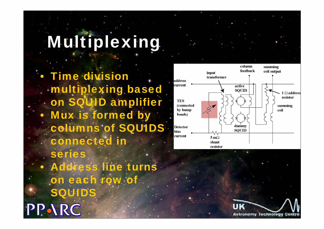
Multiplexing
• Time division multiplexing based on SQUID amplifier
• Mux is formed by columns of SQUIDS connected in series
• Address line turns on each row of SQUIDS

SCUBA-2 focal planes
• 4 × 1280 pixel sub-arrays in each focal plane
• 100mK operation using liquid cryogen-free dilution refrigerator

In-focal-plane multiplexersActive SQUID
Inputtransformer
A full-sized (32 × 40 pixel) multiplexer wafer with detail of the layout shown in the insets.

Detector fabrication processBump bonding mux to detector
Deep etching to isolate detector pixels
100 μm

Pixel Structure
Multiplexer Chip
Detector array
Indium Bump Bonds

Photoresist mask
Implantation
Bottom Wafer
Process sequence for detector

Photoresist strip
Screen Oxidation

Oxidation for Si brick etching
Top Wafer

Etch racetracks


Bond wafers

Grind back
odd number of ¼wavelengths

Nitride deposition

Etch oxide mask

Bond pads, TES and interconnect

Nitride membrane
Indium bumps Bump Bond
Process sequence for hybridised detector/mux pair

Remove handle
Process sequence for detector/mux pair
Nitride membrane
Indium bumps

Etch oxide etch stop
Process sequence for detector/mux pair
Nitride membrane
Indium bumps
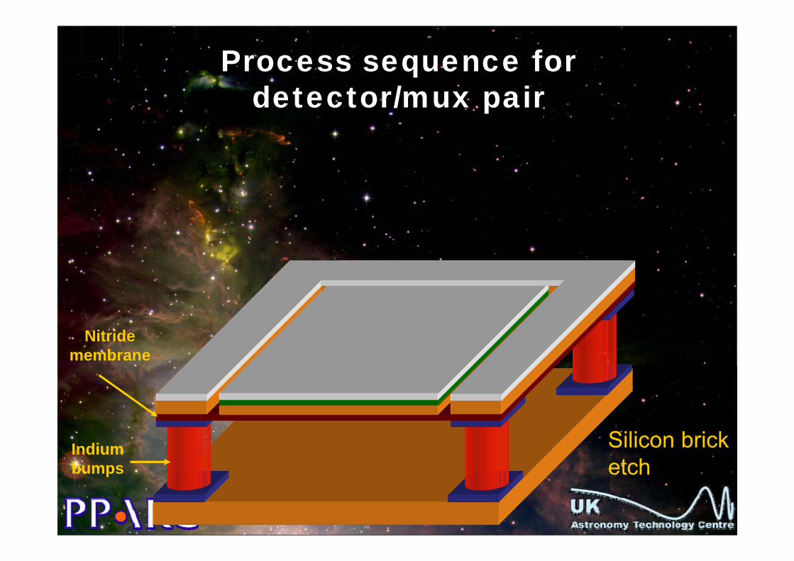
Silicon brick etch
Process sequence for detector/mux pair
Nitride membrane
Indium bumps

Completed sub-array
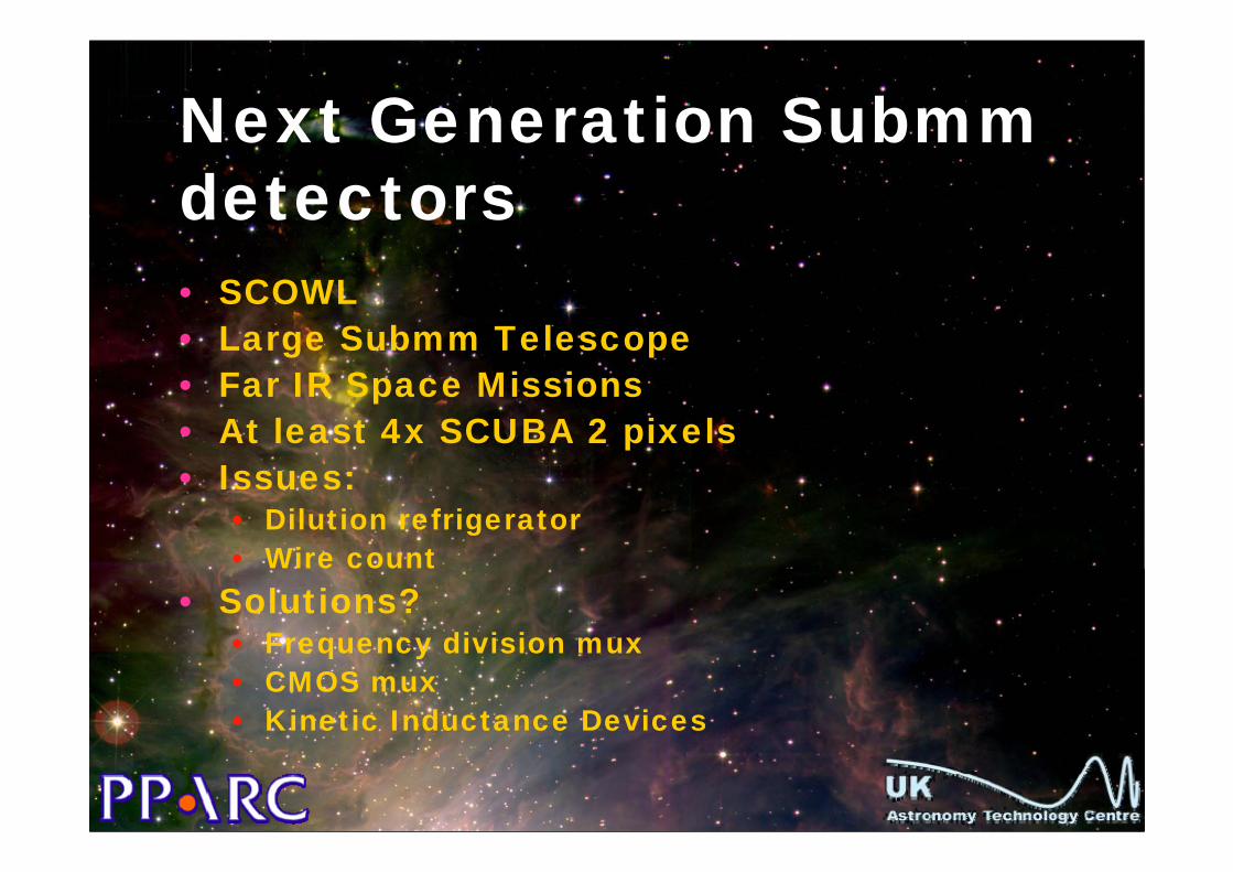
Next Generation Submm detectors• SCOWL• Large Submm Telescope• Far IR Space Missions• At least 4x SCUBA 2 pixels• Issues:
• Dilution refrigerator• Wire count
• Solutions?• Frequency division mux• CMOS mux• Kinetic Inductance Devices

SDW 2005 _ 20.6.2005_S.D’Odorico/ 10
SCOWL (SCUBA at OWL)
Concept Study carried out by ATC (P.I. I. Egan)
Imager in the 350 and 450 μm bands (850 μm desiderable)
FOV 2 x 2 arcmin, Surveyer for ALMA targets Resolution <2 arcsec
4 SCUBA 2 TES Detectors (20480 pix)
Transition Edge Sensors hybridized to a Superconducting Quantum Interference Design (SQUID) time-division multiplexer
Ceramic PCB 40x32 sub-array
NiobiumFlex Cable
Woven Cables to Room Temperature
SQUIDSeriesArray
Amplifiers
Ceramic PCB 40x32 sub-array
NiobiumFlex Cable
Woven Cables to Room Temperature
SQUIDSeriesArray
Amplifiers
subarray
Readout PCBs
subarray
Readout PCBs

Contrast with Particle Physics Detector Development• Range of development mechanisms
• Industry based > Academic based• IR detectors coming from Defence-
based industry – but now 50% of Rockwell IR business in Astronomy
• Submm detectors developed by research labs and Universities –more like PP detectors
• Should we take this approach for ELT detectors?

Mechanisms for joint detector developmentConsortia
• Example 2kx4k CCDs developed by E2V• Opticon FP6 programme > Adaptive
Optics detectors• Big projects
• JWST• XEUS• ELT
• Global Tech Dev programme? Lobby companies, maximise order size

Next step: Develop European Roadmap for Detectors for Astronomy ?• Using Opticon Key Technology
Network• Coordinated by UK• Include ESA & ESO
• More on Space Missions in Andrew Holland’s Talk


Acknowledgements
• Doug Simons, Gemini• Mark Clampin, NASA Goddard• Anthony Walton, Scottish
Microelectronics Centre• Wayne Holland, UK ATC• Roger Haynes, Anglo Australian
Observatory• Andy Longmore, UK ATC