determination of the adhesive fracture energy g of ... · determination of the adhesive fracture...
TRANSCRIPT

476RMZ – Materials and Geoenvironment, Vol. 55, No. 4, pp. 476–489, 2008
Review paper
Determination of the adhesive fracture energy GC of structural adhesives using DCB and Peel tests
Določitev raztržne žilavosti strukturnih adhezivov GC z uporabo DCB in odluščnih preizkusov
MarTin laMuT1, raDo TurK2, MaTjaž TorKar1
1Institute of Metals and Technology, Lepi pot 11, SI-1000 Ljubljana, Slovenia; E-mail: [email protected], [email protected]
2 University of Ljubljana, Faculty of Natural Sciences and Engineering, Aškerčeva cesta 12, SI-1000 Ljubljana, Slovenia; E-mail: [email protected]
Received: October 13, 2008 Accepted: November 24, 2008
Abstract: Due to the increasing use of adhesively bonded load bearing joints in de-manding Engineering applications, the failure properties of adhesives need to be known.The fracture testing of adhesive joints has been developed to yield engineering data used for comparative analysis between adhesives and also the different substrates used. A large number of different tests have been developed to measure the adhesive fracture toughness, GC, of adhe-sive joints. In this work two different types of test are presented, an elastic plastic peel test and a double cantilever beam test, based on linear elastic fracture mechanics (LEFM). Ideally, adhesive fracture toughness should be a geometry independent value, a characteristic adhesive property.
Izvleček: Zaradi vse večje uporabe adhezivnih spojev v avtomobilski in letalski industriji je poznavanje mehanskih lastnosti adhezivov izrednega pomena. Preizkušanje zlepljenih spojev z uporabo strukturnih adhezivov je bilo v prvi vrsti razvito za pridobitev primerjalnih podatkov različnih adhezivov in podlag, uporabljenih pri spojih. Obstaja veliko različnih geometrijskih ob-lik preizkusov za določitev energije raztržne žilavosti strukturnih adhezivov. V tem delu sta predstavljena dva osnovna tipa geometrije, in sicer: elasto-plastični odluščni preizkus in preizkus z uporabo dvojnega konzolnega nosilca (DCB), ki je osnovan na linearni mehaniki loma. Idealno je energija raztržne žilavosti adhezivov neodvisna karakteristična veličina adheziva.
Key words: fracture tests, adhesives, Peel tests, DCB testKljučne besede: lomni preizkusi, adhezivi, odluščni preizkusi, DCB-preizkusi

477Determination of the adhesive fracture energy GC...
RMZ-M&G 2008, 55
IntroductIon
Adhesive joints are an effective way of connecting structural components such as metals and polymers. Comparing to the traditional joining techniques riveting and welding adhesively bonded structures experience many advantages. The most important in aerospace and automotive industry are weight savings and good dy-namic fatigue properties [1]. The effective bonding of sheet materials also makes it very appealing for the packing industry. There have been a large number of differ-ent tests developed to obtain the fracture resistance of structural adhesive joints [1], among them are two of particular interest for this work: the double cantilever beam bending test (DCB), which is based on a linear-elastic fracture mechanics (LEFM), and the elastic-plastic T-peel test, both tests yield the adhesive fracture tough-ness GC. Guidance on conducting fracture tests is described in various standards, e.g. for a DCB test geometry there is a Brit-ish standard BS 7991 [2], the existing ISO standards: ISO 8510-1 1990 [3] and ISO 8510-2 1990 [4] “Peel test for a flexible bonded to rigid specimen assembly, Part 1 90° peel and Part 2 180°”, ISO 11339 1993 “180 peel test for flexible to flexible bonded assemblies” (T-peel test), indi-cate how to measure peel strength, force per unit width for peeling. To determine the adhesive fracture toughness from the measured peel strength described in the ISO standards, a special protocol was de-veloped at the Imperial College, called ICPeel [5].
dcB tEst prIncIplEs
IntroductionOne of the most frequently used test ge-ometries for generating Mode I adhesive fracture energy, GIC, is the double can-tilever beam specimen. In this test the substrates, usually made from metal, are bonded together with the adhesive and the crack is propagated along the adhesive lay-er in opening mode by pin loading at the beam-ends. The method used to determine the fractural resistance is based on linear elastic fracture mechanics (LEFM). From this test, both the resistance to crack ini-tiation and propagation can be determined and the resistance curve (plot of GIC vs. crack length) can be produced [2].
DCB specimen geometryGenerally a DCB test specimen is suited for testing joints, where relatively thin sheets of fibre composite materials are adhesively bonded, but may also be used for metal-lic substrates. A typical specimen used for metallic substrates is shown in Figure 1.
Test procedureTest is preformed under normal conditions (23 °C ± 2 °C, 50 % ± 5 % r. h.) on a ten-sile testing machine, capable of producing a constant cross-head displacement rate between 0.1 mm/min and 5 mm/min in dis-placement control. A special fixture is used to introduce the load to the pins inserted into substrate beams. The tensile testing machine compliance must be taken into account. If the machine compliance is not known, it should be de-termined using the calibrated specimens [2].

478 laMuT, M., TurK, r., TorKar, M.
RMZ-M&G 2008, 55
During the test progress, recording of the complete load versus displacement curves are taken. At the same time the crack is measured using a travelling microscope or a video camera.
Analysis methods or determining the values GIC There are three analyses methods that may be used to calculate GIC from the DCB test data, where I denotes Mode I loading condition.
simple beam theory (SBT), (1) corrected beam theory (CBT), and(2) experimental compliance method (ECM). (3)
All of them are essentially derived from Equation (2.1), and all require the monitor-ing of load, crack opening displacement, and crack growth to determine variation of
Figure 1: DCB test specimen geometry [2]. Where: A - insert film length, distance between the end of the specimen and the tip of the insert film, a - crack length, distance between the load line and the tip of the crack, a0 - initial crack length, ap - precrack length, distance from the load line to the tip of the precrack, B - specimen width, h - arm thickness, ha - adhesive layer thickness, l - specimen length.Slika 1: Geometrija DCB-preizkušanca. Oznake: A - dolžina vstavljenega traku, razdalja med koncem preizkušanca in začetkom razpoke, a - dolžina razpoke, razdalja med linijo obremenitve in vrhom razpoke, a0 - začetna dolžina razpoke, ap - dolžina predrazpoke, B - širina preizkušanca, h - širina konzolnega nosilca, ha - debelina adheziva, l - dolžina preizkušanca.
compliance with crack growth. A brief out-line of every analysis method is discussed at this point.
Simple beam theory.The value of adhesive fracture energy GIC may be deduced from:
(2.1)
where C is the compliance and is given by load-line displacement(δ)/load(P). The compliance change with crack length was derived by MoSToVoy at al. [6] where bend-ing and shear deflection contribute to the specimen compliance. The specimen was treated as a pair of cantilever beams with length a, representing the crack length, measured from the point of loading. The

479Determination of the adhesive fracture energy GC...
RMZ-M&G 2008, 55
dC/da may be written as
(2.2)
where ES is the flexural or tensile modu-lus of the substrate. This value is quoted for the standard grade materials, otherwise should be measured from an independent modulus test.
Inserting expression for dC/da into equa-tion (2.1) gives GIC
(2.3)
This value can be further simplified if the condition a2 >> h2 is met, it means that the crack length is much larger than the beam arm thickness and deflection due to shear stress can be neglected
(2.4)
where h, B, and ES are the height, width and Young’s modulus of the substrate, re-spectively.
Corrected beam theoryThe simple beam theory does not account for the important effect of beam root ro-tation, which affects compliance and GIC. It has been shown that this effect can be modelled by adding a length, Δ, to the measured crack length [8]. Adhesive frac-ture energy may be calculated using the following equation
(2.5)
where δ is the measured load-line dis-placement, F is a correction factor which accounts for the reduction in bending mo-ment caused by large displacements and N is the load block correction. When piano hinges are drilled directly through the sub-strate, as is the case for metal substrates, N = 1. Further information can be found [8, 2,
9], where detailed explanations and deriva-tion of the variables are provided.
Experimental compliance methodIn order to estimate the change of compli-ance in relation to crack growth, compli-ance is plotted against crack length and then curve fitted using the Berrys method [9], which employs a power-law compli-ance calibration
(2.6)
where k and n are regression coefficients determined from experiments. Differen-tiating this equation with respect to crack length, a, and combining the differential with Equation (2.1) leads to
(2.7)
Elasto-plastIc pEEl tEsts
IntroductionPeel test is a widely used method for meas-uring the peeling energy between flexible joints [1]. The level of the bond strength is a critical issue since laminates act as engi-neering structures, therefore it is very im-portant to be able to control adhesive frac-ture toughness. Ideally, adhesive fracture toughness should be a characteristic adhe-
480 laMuT, M., TurK, r., TorKar, M.
RMZ-M&G 2008, 55
sive property, independent of test geometry such as the thickness of the peel arm or peel angle [1]. Due to the fact of wide application of peel tests, several test geometries have been used. Two particular forms used in this work are the fixed arm peel test and T-peel test (Figures 3, 4). Since the T peel test may be seen as a two fixed arm tests combined, the fixed arm peel test is analysed firstly and then extended to T-peel test.
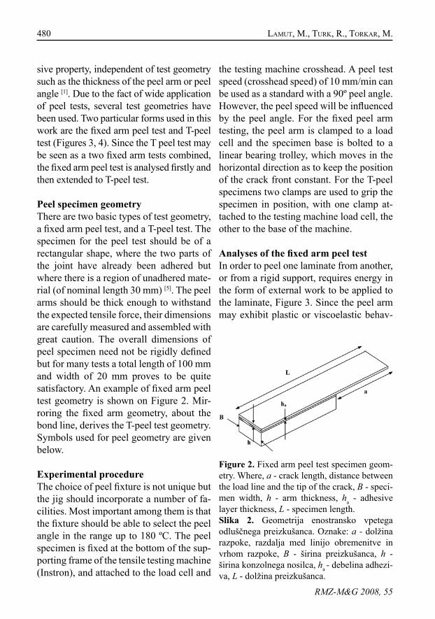
Peel specimen geometryThere are two basic types of test geometry, a fixed arm peel test, and a T-peel test. The specimen for the peel test should be of a rectangular shape, where the two parts of the joint have already been adhered but where there is a region of unadhered mate-rial (of nominal length 30 mm) [5]. The peel arms should be thick enough to withstand the expected tensile force, their dimensions are carefully measured and assembled with great caution. The overall dimensions of peel specimen need not be rigidly defined but for many tests a total length of 100 mm and width of 20 mm proves to be quite satisfactory. An example of fixed arm peel test geometry is shown on Figure 2. Mir-roring the fixed arm geometry, about the bond line, derives the T-peel test geometry. Symbols used for peel geometry are given below.
Experimental procedureThe choice of peel fixture is not unique but the jig should incorporate a number of fa-cilities. Most important among them is that the fixture should be able to select the peel angle in the range up to 180 ºC. The peel specimen is fixed at the bottom of the sup-porting frame of the tensile testing machine (Instron), and attached to the load cell and
the testing machine crosshead. A peel test speed (crosshead speed) of 10 mm/min can be used as a standard with a 90º peel angle. However, the peel speed will be influenced by the peel angle. For the fixed peel arm testing, the peel arm is clamped to a load cell and the specimen base is bolted to a linear bearing trolley, which moves in the horizontal direction as to keep the position of the crack front constant. For the T-peel specimens two clamps are used to grip the specimen in position, with one clamp at-tached to the testing machine load cell, the other to the base of the machine.
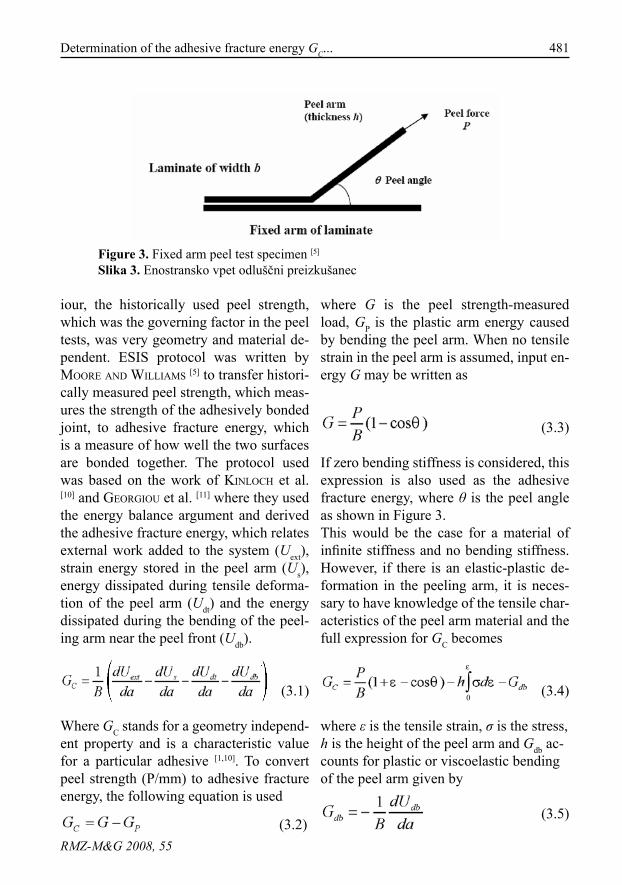
Analyses of the fixed arm peel testIn order to peel one laminate from another, or from a rigid support, requires energy in the form of external work to be applied to the laminate, Figure 3. Since the peel arm may exhibit plastic or viscoelastic behav-
Figure 2. Fixed arm peel test specimen geom-etry. Where, a - crack length, distance between the load line and the tip of the crack, B - speci-men width, h - arm thickness, ha - adhesive layer thickness, L - specimen length.Slika 2. Geometrija enostransko vpetega odluščnega preizkušanca. Oznake: a - dolžina razpoke, razdalja med linijo obremenitve in vrhom razpoke, B - širina preizkušanca, h - širina konzolnega nosilca, ha - debelina adhezi-va, L - dolžina preizkušanca.
481Determination of the adhesive fracture energy GC...
RMZ-M&G 2008, 55
iour, the historically used peel strength, which was the governing factor in the peel tests, was very geometry and material de-pendent. ESIS protocol was written by Moore anD WilliaMS [5] to transfer histori-cally measured peel strength, which meas-ures the strength of the adhesively bonded joint, to adhesive fracture energy, which is a measure of how well the two surfaces are bonded together. The protocol used was based on the work of Kinloch et al. [10] and GeorGiou et al. [11] where they used the energy balance argument and derived the adhesive fracture energy, which relates external work added to the system (Uext), strain energy stored in the peel arm (Us), energy dissipated during tensile deforma-tion of the peel arm (Udt) and the energy dissipated during the bending of the peel-ing arm near the peel front (Udb).
(3.1)
Where GC stands for a geometry independ-ent property and is a characteristic value for a particular adhesive [1,10]. To convert peel strength (P/mm) to adhesive fracture energy, the following equation is used
(3.2)
Figure 3. Fixed arm peel test specimen [5]
Slika 3. Enostransko vpet odluščni preizkušanec
where G is the peel strength-measured load, GP is the plastic arm energy caused by bending the peel arm. When no tensile strain in the peel arm is assumed, input en-ergy G may be written as
(3.3)
If zero bending stiffness is considered, this expression is also used as the adhesive fracture energy, where θ is the peel angle as shown in Figure 3. This would be the case for a material of infinite stiffness and no bending stiffness. However, if there is an elastic-plastic de-formation in the peeling arm, it is neces-sary to have knowledge of the tensile char-acteristics of the peel arm material and the full expression for GC becomes
(3.4)
where ε is the tensile strain, σ is the stress, h is the height of the peel arm and Gdb ac-counts for plastic or viscoelastic bending of the peel arm given by
(3.5)
dbC GdhBPG −−−+= ∫
ε
εσθε0
)cos1(

482 laMuT, M., TurK, r., TorKar, M.
RMZ-M&G 2008, 55
Analysis of the T-peel test
In Figure 4, the specimen configuration of T-peel-test is shown. The analysis adopts the same steps as in the fixed peel arm, except that now two peel arms are con-sidered instead of one. If one peel arm is stiffer than the other, as in the case of unbalanced peeling, two different peel an-gles are present rather then two 90° angles. Since the angles are correlated via Φ = π – θ, only one angle should be considered. The Equation (3.3) becomes:
(3.6a)
(3.6b)
where subscripts 1 and 2 stand for each peel arm. In a similar manner there will be two forms of plastic peel arm dissipative energy, which results in two forms of frac-ture toughness energy expressions:
(3.7a)
Figure 4. T-peel-test specimen [5]
Slika 4. Odluščni preizkušanec v obliki črke T ali T-odluščni preizkušanec
(3.7b)
The adhesive fracture toughness is simply the sum of the last two equations:
(3.8)
When balanced T-peel test is assumed, Φ = θ = 90º, cosθ becomes equal to zero, and all the equations derived for fixed arm peel test at 90º may be multiplied by 2, hence describe the situation in T-peel test.
In order to determine GC, from peel tests, elastic and plastic deformations are taken into account, and two tests must be con-ducted: (1) Peel test(2) Tensile test of the peel arm materialAll the detailed calculations regarding peel tests are given in references [5, 10, 11] and while theoretical calculations can be very complex, software that may be used to conduct the calculation is available on the Imperial College web site [12].
rEsults and dIscussIon
In DCB experiment mild steel beam arms (E = 207 GPa) and ESP110 (E = 4 GPa) adhe-sive were used. The geometry details of the DCB test specimen are given in Table 1. All data analysis were preformed using the Microsoft Excel© spreadsheets, which were written at Imperial College and can be obtained freely from [9,12]. The spread-sheets automatically performed all the data reduction, plots and calculations of GC, us-ing the presented theory.
483Determination of the adhesive fracture energy GC...
RMZ-M&G 2008, 55
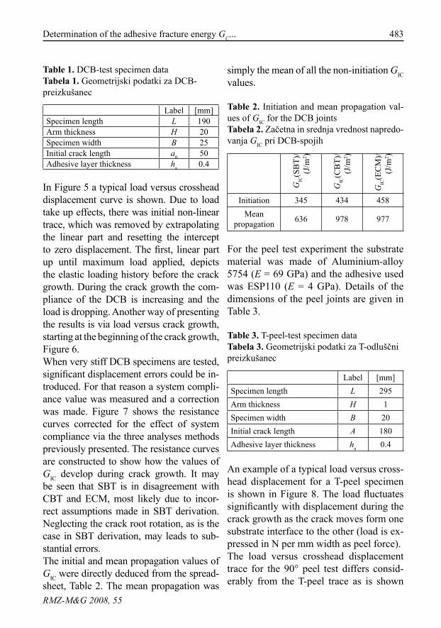
Table 1. DCB-test specimen dataTabela 1. Geometrijski podatki za DCB-preizkušanec
Label [mm]Specimen length L 190Arm thickness H 20Specimen width B 25Initial crack length a0 50Adhesive layer thickness ha 0.4
In Figure 5 a typical load versus crosshead displacement curve is shown. Due to load take up effects, there was initial non-linear trace, which was removed by extrapolating the linear part and resetting the intercept to zero displacement. The first, linear part up until maximum load applied, depicts the elastic loading history before the crack growth. During the crack growth the com-pliance of the DCB is increasing and the load is dropping. Another way of presenting the results is via load versus crack growth, starting at the beginning of the crack growth, Figure 6. When very stiff DCB specimens are tested, significant displacement errors could be in-troduced. For that reason a system compli-ance value was measured and a correction was made. Figure 7 shows the resistance curves corrected for the effect of system compliance via the three analyses methods previously presented. The resistance curves are constructed to show how the values of GIC develop during crack growth. It may be seen that SBT is in disagreement with CBT and ECM, most likely due to incor-rect assumptions made in SBT derivation. Neglecting the crack root rotation, as is the case in SBT derivation, may leads to sub-stantial errors. The initial and mean propagation values of GIC were directly deduced from the spread-sheet, Table 2. The mean propagation was
simply the mean of all the non-initiation GIC values.
Table 2. Initiation and mean propagation val-ues of GIC for the DCB jointsTabela 2. Začetna in srednja vrednost napredo-vanja GIC pri DCB-spojih
GIC
(SB
T)/
(J/m
2 )
GIC
(CB
T)/
(J/m
2 )
GIC
(EC
M)/
(J/m
2 )
Initiation 345 434 458Mean
propagation 636 978 977
For the peel test experiment the substrate material was made of Aluminium-alloy 5754 (E = 69 GPa) and the adhesive used was ESP110 (E = 4 GPa). Details of the dimensions of the peel joints are given in Table 3.
Table 3. T-peel-test specimen dataTabela 3. Geometrijski podatki za T-odluščni preizkušanec
Label [mm]Specimen length L 295Arm thickness H 1Specimen width B 20Initial crack length A 180Adhesive layer thickness ha 0.4
An example of a typical load versus cross-head displacement for a T-peel specimen is shown in Figure 8. The load fluctuates significantly with displacement during the crack growth as the crack moves form one substrate interface to the other (load is ex-pressed in N per mm width as peel force). The load versus crosshead displacement trace for the 90° peel test differs consid-erably from the T-peel trace as is shown

484 laMuT, M., TurK, r., TorKar, M.
RMZ-M&G 2008, 55
Figure 5. A typical load-displacement trace for a DCB joint [7]
Slika 5. Značilen potek krivulje obremenitev-pomik čeljusti, pri DCB-spojih
Figure 6. A typical load-crack growth trace for a DCB joint [7]
Slika 6. Značilen potek krivulje obremenitev-rast razpoke, pri DCB-spojih

485Determination of the adhesive fracture energy GC...
RMZ-M&G 2008, 55
Figure 7. A typical set of resistance curves for a DCB joint [7]
Slika 7. Značilne krivulje raztržne žilavosti DCB-spojev
Figure 8. A typical load-displacement trace for a T-peel testSlika 8. Značilen potek krivulje obremenitev-pomik čeljusti za T-odluščni preizkušanec

486 laMuT, M., TurK, r., TorKar, M.
RMZ-M&G 2008, 55
in Figure 9. Only minor load fluctuations with displacement during crack growth are observed. It can be said that the load reaches a steady state value after a certain amount of crack growth. Using the spreadsheet for peel tests and the data obtained from the experiment the val-ues of GI can be easily obtained, although the calculations may look fairly complicat-ed. Since the mean steady state peel force is used in the calculations, the GI represents the propagation value. It is almost impos-sible to detect the beginning of the crack growth for these tests therefore the initia-tion value of GI is not attainable.
Table 4. Propagation values of GC for the peel testsTabela 4. Obremenitev in GC odluščnih preizkusov
P/(N/mm) GI/(J/m2)T-peel 7.43 1370
90° peel 5.00 922
From table 4 it may be seen that the adhe-sive fracture toughness between T-peel and 90 ° peel tests differ greatly, which is most likely due to an unsteady crack growth. There is a combination of adhesive and cohesive fracture, for which cohesive and adhesive fracture toughness should be de-termined.
conclusIons
Firstly, a LEFM-based approach was pre-sented via DCB test geometry. To calcu-late GIC (Mode I loading condition) from a DCB specimen, three methods were presented. Corrected beam theory and Ex-perimental compliance method both yield accurate results, whereas Simple beam theory can only be applied under specific conditions. Secondly, two types of elastic plastic peel tests were presented. Fixed arm peel test
Figure 9. A typical load-displacement trace for a 90° peel testSlika 9. Značilen potek krivulje obremenitev-pomik čeljusti za 90-stopinjski odluščni preizkušanec

487Determination of the adhesive fracture energy GC...
RMZ-M&G 2008, 55
(90° peel test) and the T-Peel test were introduced to show how the plastic de-formation and root rotation of the beam arms is accounted for in determining the fracture toughness of adhesives. All the steps needed to transfer experimentally obtained data, peel strength to fracture toughness of the adhesive, were outlined. Additionally, the experimental results, the load versus crosshead displacement trac-es, were shown for DCB and Peel tests. All data manipulations were made using the Microsoft Excel© spreadsheets. It may be seen that the SBT gives inferior results comparing to CBT and EC methods. The adhesive fracture toughness, GC, from the DCB and 90° peel tests agreed well. On the other hand the value for the T-peel test is higher, which is in disagree-ment with the statement of characteristic adhesive property. In order to obtain an excellent agreement, further studies must be performed, where special care must be dedicated to the test specimen prepara-tion and test procedure to ensure cohesive fracture through the adhesive layer.
povzEtEk
Adhezivna sredstva so učinkovit način spajanja različnih strukturnih elementov, kot so kovine in polimeri. V primerjavi s tradicionalnimi metodami spajanja imajo adhezivni spoji številne prednosti, med katerimi so za letalsko in avtomobilsko industrijo najpomembnejša zmanjšanje mase. Obstaja veliko različnih geometrij preizkusov za določitev energije loma
strukturnih adhezivov. V tem delu sta predstavljena dva osnovna tipa geometrije: elasto-plastični odluščni preizkus in preiz-kus z uporabo dvojnega konzolnega nosilca (DCB), ki je osnovan na linearni mehaniki loma. Natančna navodila in opis opravl-janja različnih preizkusov so predstavljena v različnih standardih, npr. za DCB obstaja BS 7991 [2], za odluščne preizkuse imamo več ISO-standardov: ISO 8510-1 1990 [3], ISO 8510-2 1990 [4] in ISO 11339 1993. Za izračun energije loma iz izmerjene sile pri različnih preizkusih je bil na Imperial Col-legeu razvit ICPeel [5] protokol. Najbolj razširjen preizkus za izračun en-ergije loma, GIC, pri načinu obremen-jevanja I, je DCB-preizkus z uporabo dvo-jnega konzolnega nosilca (Slika 1), kjer sta konzoli navadno kovinski in razpoka poteka vzdolž adheziva ob obremenitvi na krajiščih konzol. S tem preizkusom lahko določimo odpornostno energijo pričetka rasti in energijo rasti razpoke ter izračunamo krivulje energije loma v odvis-nosti od dolžine razpoke. Za izračun en-ergije loma obstajajo tri teorijske metode: (1) enostavna teorija konzolnega nosilca;(2) popravljena teorija konzolnega nosilca;(3) eksperimentalna metoda s podajnostjo (ang. compliance).Odluščni preizkusi se uporabljajo za določanje odluščne energije pri fleksibil-nih spojih, kjer je težko ločiti med energijo loma adheziva in deformacijsko energijo posameznih elementov spoja. Idealno je energija loma adhezivov neodvisna, karakteristična veličina adheziva. Med različnimi geometrijami odluščnih preiz-kusov sta v tem delu predstavljeni dve:

488 laMuT, M., TurK, r., TorKar, M.
RMZ-M&G 2008, 55
enostransko vpet odluščni preizkušanec (Slika 2) in odluščni preizkušanec v obliki črke T ali T-odluščni preizkušanec (Slika 4). Pri enostransko vpetem odluščnem preizkušancu obstaja več variacij, ki se razlikujejo v kotu med fiksiranim in obremenjenim delom preizkušanca, npr. 90-stopinjski odluščni preizkus (Slika 3). V primeru preslikanja enostransko vpetega odluščnega preizkušanca preko adhezivne plasti dobimo T-odluščni preizkušanec, kar olajša analizo odluščnih preizkušancev. Pri DCB- preizkusih so bili uporabljeni jekleni konzolni nosilci (E = 207 GPa) in adheziv z oznako ESP110 (E = 4 GPa) Ge-ometrijski podatki DCB-preizkušanca so podani v Tabeli 1. Pri odluščnih preizkusih je bila kot podla-ga uporabljena aluminijeva zlitina 5754 (E = 69 GPa) in enak adheziv kot v prejšnjem primeru ESP110 (E = 4 GPa). Vsi geometr-ijski podatki, uporabljeni pri odluščnih preizkusih, so zbrani v Tabeli 3. Prikazane so značilne krivulje obremen-itev-pomik čeljusti za vse obravnavane preizkuse (Slike 5, 8, 9). Na Sliki 6 je vi-den padec obremenitve med potekom rasti razpoke pri DCB- preizkusu. Za DCB- preizkus so prikazane krivulje energije loma (Slika 7), izračunane iz eksperimetal-nih podatkov in z uporabo ICPeel-protoko-la, ki obsega predstavljeno teorijo. Iz Tabel 2 in 4 je razvidno, da se energija loma adheziva med DCB in 90°-odluščnim preizkusom dobro ujema, medtem ko je vrednost pri T-odluščnem preizkusu višja in se ne ujema z načelom o karakteristični lastnosti energije loma adheziva.
rEfErEncEs
[1] Kinloch, a. j. (1987): Adhesion and Adhesives. 1st edition. Chapman and Hall, London.
[2] BSI. (2001). Determination of the mode I adhesive fracture energy, G, of structural adhesives using the double cantilever beam (DCB) and tapered-cantilever beam (TDCB) specimens. BS 7991.
[3] ISO: Adhesives – Peel test for a flexi-ble-bonded-to-rigid test specimen assembly – Part 1. ISO 8510-1:1990.
[4] ISO: Adhesives – Peel test for a flexi-ble-bonded-to-rigid test specimen assembly – Part 2. ISO 8510-2:1990.
[5] Moore, D. r. & WilliaMS, j. G.: A protocol for Determination of the Adhesive Fracture Toughness of Flexible Laminates by Peel Test-ing: Fixed Arm and T-peel Meth-ods ESIS protocol, updated 2006 [cited 20. 12. 2006]. Accessible on Internet: <http://www3.impe-rial.ac.uk/meadhesion>.
[6] MoSToVoy, S., croSley, P. B. & riPlinG, e. j. (1967): Use of crack-line-load specimens for measuring plane strain fracture toughness. J. Mat. 2, pp. 661–681.
[7] BlacKMan, B. r. K., Kinloch, a. j., ParaSchi, M. & Teo, W. S. (2003): Measuring the mode I adhesive fracture energy, GIC, of structural adhesive joints: the results of an

489Determination of the adhesive fracture energy GC...
RMZ-M&G 2008, 55
international round-robin. Int. J. Adhes. Adhes. 23, pp. 293–305.
[8] haSheMi, B., Kinloch, a. j. anD Wil-liaMS, j. G. (1990): The analysis of interlaminar fracture in uniaxial fibre-polymer composites. Proc. R. Soc. London A. 427, pp. 173–199.
[9] BlacKMan, B. r. K.& Kinloch, a. j.: Protocol for Determination of the Mode I Adhesive Fracture Energy, GIC, of Structural Adhesives us-ing the Double Cantilever Beam (DCB) and Tapered Double Can-tilever Beam (TDCB) Specimens. Imperial College London, 2000, updated 2006 [cited 20.12. 2006]. Accessible on Internet: <http://
www3.imperial.ac.uk/meadhe-sion>.
[10] Kinloch, a. j., lau, c. c. & WilliaMS, j. G. (1994): The peeling of flex-ible laminates. Int. J. Frac. 66, pp. 45–70.
[11] GeorGiou, i., haDaVinia, h., iVanKo-Vic, a., Kinloch, a. j., TroPSa, V. & WilliaMS, j. G. (2003): Cohe-sive zone models and the plasti-cally deforming peel test. J. Adh. 79, pp. 239–265
[12] Imperial College London Website [online]. Peel test protocols: ICPeel. updated 2006 [cited 20.12. 2006]. Accessible on In-ternet: <http://www.me.ic.ac.uk/AACgroup/>.