determination of the ground vibration attenuation law from
TRANSCRIPT

lable at ScienceDirect
Journal of Rock Mechanics and Geotechnical Engineering 13 (2021) 1182e1192
Contents lists avai
Journal of Rock Mechanics andGeotechnical Engineeringjournal homepage: www.jrmge.cn
Technical Note
Determination of the ground vibration attenuation law from a singleblast: A particular case of trench blasting
Rafael Rodríguez a,*, Laura García de Marina a, Marc Bascompta b, Cristóbal Lombardía a,c
aDepartment of Mining Exploitation and Prospecting, School of Mining, Energy and Materials Engineering, University of Oviedo, Independencia 13, Oviedo, 33004,SpainbDepartment of Mining, Industrial and ICT Engineering, Polytechnic University of Catalonia (UPC), Manresa, Av. Bases de Manresa, 61-73, Barcelona, 08242, Spainc Perforaciones Noroeste S.A, Longoria Carbajal No. 3, Oviedo, 33004, Spain
a r t i c l e i n f o
Article history:Received 8 October 2020Received in revised form21 January 2021Accepted 7 March 2021Available online 14 July 2021
Keywords:Empirical analysisBlastingGround vibrationTrenchingWave propagation
* Corresponding author.E-mail address: [email protected] (R. Rodríguez)Peer review under responsibility of Institute of R
nese Academy of Sciences.
https://doi.org/10.1016/j.jrmge.2021.03.0161674-7755 � 2021 Institute of Rock and Soil MechanicNC-ND license (http://creativecommons.org/licenses/
a b s t r a c t
The general transmissivity law of ground vibrations was studied, and a user-friendly methodology fordetermining the behavior of vibrations generated in any rock mass is proposed. The study was based on asingle blast in a trench excavation, analyzing the vibration components recorded from two fixed loca-tions. The attenuation law and the main variables according to the legal requirements, frequency andpeak particle velocity (PPV), are defined with this novel method, achieving a high confidence level in asimple manner. The proposed approach can also have an important impact in terms of reducing thepotential consequences of vibrations for the surrounding construction and achieving the requireddefinition of rock mass. Reducing the cost and time in many projects where blasting techniques areapplied is particularly useful for the design of future blasts.� 2021 Institute of Rock and Soil Mechanics, Chinese Academy of Sciences. Production and hosting byElsevier B.V. This is an open access article under the CC BY-NC-ND license (http://creativecommons.org/
licenses/by-nc-nd/4.0/).
1. Introduction
The use of explosive charges is a widely adopted technique forrock mass breakage in mining and civil works due to its low directand indirect costs (López-Jimeno et al., 2017). Therefore, it is crucialto properly define the main blasting features, such as the blastholegeometry, detonation scheme, and type of explosive, and to studythe geotechnical characteristics of the rock mass that need to bebroken (Kuzu, 2008).
On the other hand, many potential negative effects existregarding the surrounding environment, the most important ofwhich are flyrocks, seismic waves, and airblasts, and it is necessaryto control them in order to comply with the existing laws andregulations. From those negative effects, seismic waves, whichcause ground vibrations, might be the most dangerous and difficultto manage. Their impact is especially relevant when there is con-struction nearby (Tripathy et al., 2016). The limit values of groundvibration levels are usually established depending on the damagethat the vibrations can cause and the type of construction, and this
.ock and Soil Mechanics, Chi-
s, Chinese Academy of Sciences. Prby-nc-nd/4.0/).
topic has been widely studied over time (Nicholls et al., 1971;Studer and Suesstrunk, 1981; Konon, 1985).
Vibrations can be defined as the transmission of the seismicwave in a blast that generates a movement of particles at eachpoint. The initiation of the blast creates a pressure wave due to theexplosive gases at high pressure and temperature. Initially, thiswave has a cylindrical shape, which subsequently evolves to aspherical shape, creating deformation of the rock mass. The vi-bration wave is initiated in the elastic stage since pressure createdduring the blast is progressively reduced in the initial stages of theprocess (López-Jimeno et al., 2017). These waves are transmittedwith very little energy consumption, mainly attenuated due to theincrease in the volume affected by them. The stream of wavesgenerated has a different frequency, mostly depending on the typeof rock mass. The velocity of transmission is also dependent on theelastic rock mass characteristics and the presence of faults andfractures, producing a refraction and reflection of thewave. At shortdistances, the main influence of the blast is the explosive andgeometric factors, while the geological characteristics and struc-tures have much more influence at long distances (De Cospedal,2019).
The behavior of the waves through the rock mass is crucial forcharacterizing the vibrations (Aldas, 2010), especially when thereare many different geological structures and variations. Each type
oduction and hosting by Elsevier B.V. This is an open access article under the CC BY-

R. Rodríguez et al. / Journal of Rock Mechanics and Geotechnical Engineering 13 (2021) 1182e1192 1183
of rock has a different response to vibrations, the higher the density,the higher the capacity to transmit vibrations (Blair and Armstrong,1999).
The influence of fracturing elements such as faults, cracking, andstrata, among others, has been analyzed by many researchers (Akand Konuk, 2008; Kuzu, 2008; Takahashi et al., 2018). The inter-action of several layers and fracturing in the direction of the wavesand their intensity were also analyzed by Shao et al. (2015) andNateghi (2011). In addition, the level of vibration was studied anddetermined to be higher in the surface of the soil than in thecontact between soil and bedrock (Wu et al., 1998). However, thevelocity in soils is usually lower than that in rock because the elasticmodulus is also lower (Jayasinghe et al., 2019). Several authors havealso tried to correlate indicators such as the uniaxial compressivestrength (UCS), geological strength index (GSI), and rock qualitydesignation (RQD) with the level of vibrations (Ozer, 2008; Mesecet al., 2010; Kumar et al., 2016). The presence of water can also bean important element in the level of vibration, increasing in manycases studied (Singh and Narendrula, 2007).
When these vibrations reach any structure in their influencearea, they can cause damage or, at a lower level, a certaindiscomfort to the residents, which can also lead to legal issues(Schexnayder and Ernzen, 1999). Therefore, it is necessary toconsider the potential effect of blasting on the environment in theearly stages of a project, especially when there are structures in theproximity (Yan et al., 2020), by considering the explosive charge,type of rock mass, and distance to the structure from the blasting.
The achievement of a transmissivity law for ground vibration isfundamental to predicting its behavior. One of the first publicationsregarding the ground vibration was the work of Rockwell (1927),studying the effect on structures. Further research has been con-ducted over time, making significant improvements to minimizethe risk of blasting (Crandel, 1949; Langefors and Kihlstrom, 1978).
It is necessary to correlate explosive charge and distance to thebuilding for each type of rock mass to control the vibration pro-duced. This information is very useful for designing the blast fea-tures, especially the maximum instantaneous charge. In somecases, this restriction can affect the length of the blastholes, theirdiameter, and any other variable. All these factors can have a hugeimpact on the price of the blasting project due to the specificstudies required.
When there are insufficient data from the blasting area, it isnecessary to use empirical prediction methods. Balsa (1989) pro-posed several interesting vibration transitivity laws based onhundreds of blasts carried out in different rock masses in Spain.Many empirical vibration prediction laws have been developedbased on the maximum instantaneous charge or maximum chargeper delay and the distance between the blast and the seismograph.However, they cannot include other characteristics of the blast(type of explosive, overlapping, delays, detonators, suitability of theblast) and the intrinsic features of the blast location. Several au-thors, such as Hudaverdi (2012) and Khandelwal and Saadat (2015),utilized empirical approaches to determine specific modelsdepending on the rock mass type.
Different artificial intelligence (AI) approaches have also beenproposed in recent years (Yu et al., 2020), using artificial neuralnetworks to predict ground vibrations (Khandelwal and Singh,2009; Álvarez-Vigil et al., 2012; Monjezi et al., 2013; Iraminaet al., 2018; Zhou et al., 2020) and probabilistic models (Zhouet al., 2021), providing interesting and reliable results.
While large quantities of data from blasts in open pit mining andquarrying can be obtained to determine the attenuation law, basedon the data collected over time from many representative points,civil works usually lack this type of information, having scarce, ornon-existent, preliminary information on rock mass behavior.
Therefore, the analysis of the first blast is crucial for obtaining asmuch information as possible.
According to the standard analysis, the recording of one blast bya seismographer stands for one point in the peak particle velocity(PPV)-scaled distance (SD) graph, from which it is not possible todetermine the specific vibration attenuation law. Nevertheless, itcould be deduced from a single blast assuming the superimpositionprinciple and signature-hole method used in several previousstudies (Stump and Reinke, 1983; Toraño et al., 2006; Hemant andMishra, 2019). This procedure is faster and cheaper than otheroptions currently used. Its application requires the following con-ditions and variables: a minimum number of blastholes, charge perdelay, and distance from blastholes to the monitoring point in awide range. Particular attention should be paid to the possibility ofhaving a wave-front reinforcement line (Richards, 2008).
The aim of this studywas to determine the vibration attenuationlaw from themonitoring of a single blast, a trench excavationwith arock mass consisting of sandstone and marl. In this regard, the casestudy has the ideal characteristics, i.e. the charge per delay and thedistance from the blastholes to the seismographers vary along thetrench. There are only two rows of blastholes, making the analysiseasier. Hence, a new approach to determine the ground vibrationattenuation law from data of only one blast is proposed, based onan empirical analysis of the vibrations related to a long linear blast.
2. Case study
2.1. A trench excavation for the project “Arteria Norte”
The blast studied was performed during the excavation ofArteria Norte, a buried water pipeline placed between La Pica andPinzales villages in Asturias, Spain.
Arteria Norte is an underground facility with more than 11.5 kmof pipelines. The system has been operating for 39 years, supplying95,000 m3 of water per day. The urgency of this renovation workwas due to the continuous failure of the old pipeline. The newconstruction is placed parallel to the old one.
Based on the rock mass characteristics, the excavability wasconsidered as moderate and in dry conditions, making it possible touse mechanical equipment in most areas (Tsiambaos and Saroglou,2010). Despite that, some other parts of the piping layout requiredblasting due to local rockmass changes and low performance of themechanical excavation. Along the trace of the newproject, there area significant number of structures that need to be protected fromthe potential damage of the blasts (Fig. 1).
2.2. Geological and geotechnical characteristics
The place is located in the Gijón-Villaviciosa basin, more spe-cifically, the Purbeck facies of the upper Jurassic or Malm, with aMeso-Tertiary origin due to the sinking of the septentrional part ofthe Asturian region caused by two deep faults, one oriented inWNW-ESE and the other in NE-SW. Over the course of its history,this basin has alternated between episodes of depression andelevation, which led to series of marine, lake, and terrigenoussediments.
The ground was directly diggable with an excavator in manyparts of the trench, using a hydraulic breaker hammer for strongerrocks. Nevertheless, both methods were inadequate in some partsof the trench with conglomerates, sandstone, and marl layers.
The conglomerate levels were studied in detail in order tocharacterize the rock excavability and design the blasting properly(Fig. 2). The UCS was sc ¼ 45 MPa, and the rock mass quality variedfrom fractured rock mass with GSI ¼ 35 and RQD ¼ 40% to a moremassive rock mass with GSI ¼ 60 and RQD ¼ 90%.
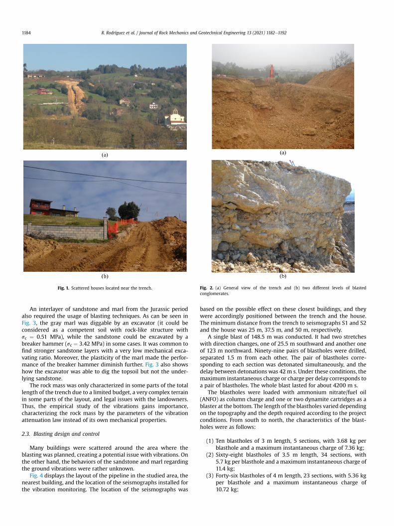
Fig. 1. Scattered houses located near the trench. Fig. 2. (a) General view of the trench and (b) two different levels of blastedconglomerates.
R. Rodríguez et al. / Journal of Rock Mechanics and Geotechnical Engineering 13 (2021) 1182e11921184
An interlayer of sandstone and marl from the Jurassic periodalso required the usage of blasting techniques. As can be seen inFig. 3, the gray marl was diggable by an excavator (it could beconsidered as a competent soil with rock-like structure withsc ¼ 0.51 MPa), while the sandstone could be excavated by abreaker hammer (sc ¼ 3.42 MPa) in some cases. It was common tofind stronger sandstone layers with a very low mechanical exca-vating ratio. Moreover, the plasticity of the marl made the perfor-mance of the breaker hammer diminish further. Fig. 3 also showshow the excavator was able to dig the topsoil but not the under-lying sandstone.
The rock mass was only characterized in some parts of the totallength of the trench due to a limited budget, a very complex terrainin some parts of the layout, and legal issues with the landowners.Thus, the empirical study of the vibrations gains importance,characterizing the rock mass by the parameters of the vibrationattenuation law instead of its own mechanical properties.
2.3. Blasting design and control
Many buildings were scattered around the area where theblasting was planned, creating a potential issue with vibrations. Onthe other hand, the behaviors of the sandstone and marl regardingthe ground vibrations were rather unknown.
Fig. 4 displays the layout of the pipeline in the studied area, thenearest building, and the location of the seismographs installed forthe vibration monitoring. The location of the seismographs was
based on the possible effect on these closest buildings, and theywere accordingly positioned between the trench and the house.The minimum distance from the trench to seismographs S1 and S2and the house was 25 m, 37.5 m, and 50 m, respectively.
A single blast of 148.5 m was conducted. It had two stretcheswith direction changes, one of 25.5 m southward and another oneof 123 m northward. Ninety-nine pairs of blastholes were drilled,separated 1.5 m from each other. The pair of blastholes corre-sponding to each section was detonated simultaneously, and thedelay between detonations was 42 m s. Under these conditions, themaximum instantaneous charge or charge per delay corresponds toa pair of blastholes. The whole blast lasted for about 4200 m s.
The blastholes were loaded with ammonium nitrate/fuel oil(ANFO) as column charge and one or two dynamite cartridges as ablaster at the bottom. The length of the blastholes varied dependingon the topography and the depth required according to the projectconditions. From south to north, the characteristics of the blast-holes were as follows:
(1) Ten blastholes of 3 m length, 5 sections, with 3.68 kg perblasthole and a maximum instantaneous charge of 7.36 kg;
(2) Sixty-eight blastholes of 3.5 m length, 34 sections, with5.7 kg per blasthole and a maximum instantaneous charge of11.4 kg;
(3) Forty-six blastholes of 4 m length, 23 sections, with 5.36 kgper blasthole and a maximum instantaneous charge of10.72 kg;

Fig. 3. (a) Gray marl and (b) sandstone in a prospecting excavation.
Fig. 4. Location of the seismographs and pipeline trace (upper) and trench viewedfrom S1 (lower).
R. Rodríguez et al. / Journal of Rock Mechanics and Geotechnical Engineering 13 (2021) 1182e1192 1185
(4) Forty-four blastholes of 4.5 m length, 22 sections, with7.24 kg per blasthole and a maximum instantaneous chargeof 14.48 kg;
(5) Thirty blastholes of 5 m length, 15 sections, with 10.24 kg perblasthole and a maximum instantaneous charge of 20.48 kg.
The blasthole inclination was approximately 1:4 (horizontal/ver-tical), and the distance between blastholes at the bottomwas around2 m. The stemming length was 2.25 m (2 m in blastholes of 3 m
length). The bottom charge lengthwas about 0.6m, corresponding totwo dynamite cartridges (only one cartridge for 3 m blastholes). Theexplosive charge for each pair of blastholes was chosen as a balancebetween the minimum amount necessary to break the rock and themaximum allowed by the ground vibration regulation.
3. Materials and methods
3.1. Vibration fundamentals
Ground vibrations are not only characteristic of a specific loca-tion but also depend on the performance conditions of the blasting.The ground vibration attenuation laws, or transmissivity laws,establish a relationship among the maximum explosive charge perdelay, distance to the blasting, and vibration speed, with the aim ofpredicting the effects of the blasting depending on the variables tobe tested. In this regard, one of the very first propagation equationswas suggested by Morris (1950):
A ¼ k
ffiffiffiffiffiffiW
p
D(1)
where A is the maximum displacement of the ground particles(mm); k is a constant dependent on the type of rock mass, whichranges from 0.57 for hard rocks to 3.4 for unconsolidated soils;W isthe mass of the explosive charge (kg); and D is the distance be-tween the blasting and the measuring point (m).
Blair and Duvall (1954) reviewed the ground vibration controltechniques and suggested that the maximum displacement of theground particles should be replaced by the sum vector of the par-ticle velocity, which would mean a change in Eq. (1):
v ¼ Kvr
ffiffiffiffiffiffiW
p
D(2)
where v is the particle velocity (mm/s), and Kvr is the empiricalparameter depending on the rock mass characteristics.
Subsequent studies considered a relationship between themaximum particle velocity, or PPV, and the so-called scaled dis-tance SD, which is defined as the distance divided by a function ofthe maximum charge per delay. It was considered that for aspherical symmetrical load, every linear dimension should be cor-rected by the cubic root of that explosive charge (Blair and Duvall,1954; Ambraseys and Hendron, 1968; Dowding, 1971; Agrawal andMishra, 2019), while the PPV is considered the most reliable vari-able for predicting vibrations (De Cospedal, 2019). The definition ofSD is expressed by
SD ¼ DQa (3)
where Q is the maximum instantaneous charge or maximumcharge per delay (kg), and the parameter a varies depending on theresearchers (Devine, 1966; Ambraseys and Hendron, 1968;Langefors and Kihlstrom, 1978).
From a general perspective, taking the maximum particle ve-locity as the most characteristic parameter, it can be affirmed thatthe intensity of the seismic waves and the scaled distance followsthe law displayed as
PPV ¼ K
D
Q1=3
!�n
(4)
where K and n are the empirical parameters depending on rockmass characteristics.

R. Rodríguez et al. / Journal of Rock Mechanics and Geotechnical Engineering 13 (2021) 1182e11921186
Although Eq. (4) was proposed initially as an empirical rela-tionship, Sambuelli (2009) proposed an analytical approach tosupport this empirical expression, pointing out that PPV dependson the geomechanical properties of the rock.
In the case of cylindrical explosive charges, it has been proventhat the distancesmust be corrected by dividing them by the squareroot of the charge (Devine, 1966). Other researchers such asHolmberg and Persson (1978) and Ghosh and Daemen (1983) didnot consider any special symmetry for the explosive load, but theyconsidered the following general expression:
PPV ¼ KQaDb (5)
where a and b are the empirical constants for a specific location,and can be determined through a multiple regression analysis.
Singh and Vogt (1998) assessed some of the main transmissivitylaws in a comparative research, finding out that all the laws differ inthe prediction of the PPV at very long distances, and it is notpossible to define the ground characteristics related to each law. Itis also not possible to predict the velocity at very short distances, upto 3e4 times the drillhole diameter, which is crucial in the case ofunderground excavations.
On the other hand, Balsa (1989) studied several thousand blasts,presenting a statistic transmissivity law for different types of rocksin Spain. Data of the explosive charge, distance from the seismo-graph to the blasting point, type of triggering, and velocity and itscomponent were used in the research. The general expression ofthe laws is represented as follows:
PPV ¼ KQaD�b (6)
where the constants K, a, and b are obtained by empirical corre-lations that include all the other factors, mainly related to thecharacteristics of the rock mass excavated. The subsequent processis performed by blasting individual charges and measuring thevelocity of the vibration for a known distance, with an adjustmentof K, a, and b for Eq. (5).
These can be obtained with a minimum quadratic linearregression calculus. If the logarithmic-normal method is applied tothe distribution of the points, it is possible to apply a security co-efficient to the obtained law. The laws were calculated with a 90%confidence in this study, considering all types of triggering andcomponents. The designated vibration frequencies of each type ofrock mass were calculated as the mean of all the measurements(Table 1).
Table 1Transmissivity laws based on the rock mass characteristics (Balsa, 1989).
Rock mass 90% law Frequency
Gypsum PPV ¼ 68077Q0:49D�1:96 5Limestone PPV ¼ 3085Q0:767D�1:651 25Cayuelaa PPV ¼ 191:6Q0:47D�1:06 15Marble PPV ¼ 5028Q0:55D�1:67 40Slate PPV ¼ 4019Q0:78D�1:66 20Dolomite PPV ¼ 24428Q0:92D�2:25 25Shale/Schist PPV ¼ 451Q0:42D�1:18 20Conglomerate PPV ¼ 1144Q0:37D�1:38 30Granite PPV ¼ 4690Q0:9D�1:69 40Basalt PPV ¼ 6410Q0:477D�2:06 30Quartzite PPV ¼ 2067Q0:55D�1:7 40
a Cayuela is a common Spanish name for a characteristic limestone formed in the Cre
3.2. Ground vibration analysis and control
A complete ground vibration analysis following the Spanishstandard UNE 22-381-93 (1993) includes two stages: before andafter the blasting. The analysis before the blasting can be used toestimate the charge per delay and the type of ground vibrationanalysis/control necessary in order to comply with the regulations.
Following the standard UNE 22-381-93 (1993), the blast has tobe represented by a point (D, QN) in Fig. 5a, where D is the distancefrom the blasting to the structure, and QN is the normalized charge.The position of the point determines the type of study according totwo lines that separate three areas in Fig. 5a. A point in the lowerzone, Zone 1, represents a blast with no risk, because the charge istoo small and/or the distance to the structure is long enough. In thiscase, the blasting is authorized without requiring any action. If thepoint is in the intermediate zone, Zone 2, the blast implies somerisks, and it can be carried out as it has been projected only if theground vibrations are controlled by a seismograph. Finally, if therepresentative point is in the upper zone, Zone 3, the blast cannotbe carried out as it poses a risk because the charge per delay is toolarge or the distance to the structure is too small. In this last sce-nario, it is necessary to carry out a preliminary study with smallexplosive charges to determine the local ground vibration attenu-ation law and design the blast based on this determined law.
In the houses near the case study blasting, it is a reasonabledecision to choose the possible maximum normalized chargewithin Zone 2. Considering that the distance is D ¼ 50 m (thenearest house is only 50 m to the trench) and the normalizedcharge has to be less than 13 kg according to Fig. 5a, the normalizedcharge QN is defined as
QN ¼ FRFSQ (7)
where FR is a coefficient depending on the rock properties and takesa value of 2.52, 1, or 0.4 for weak, medium, or strong rock mass,respectively; and FS is a coefficient depending on the structure to beprotected and takes a value of 0.28 for structures of low sensitivityto vibrations (industrial areas), 1 for medium-sensitivity structures(residential buildings), and 3.57 for structures very sensitive to vi-brations (hospital, historic heritage buildings, etc.).
Assuming FR ¼ 1 and FS ¼ 1, the maximum charge per delayshould be Q ¼ QN � 13 kg. Based on previous experience, themaximum charge per delay in the blastholes nearest to the house isQ ¼ 11.4 kg, in accordance with the Spanish regulation. Anotheranalysis can be performed before blasting, and it consists of esti-mating the level of vibrations using a known vibration attenuationlaw.
(Hz) Correlation coefficient Standard deviation
0.856 0.6620.815 0.9790.672 0.9890.916 0.5470.946 0.5470.934 0.5180.8 0.8520.879 0.6980.883 0.9390.809 0.9550.961 0.312
taceous period.
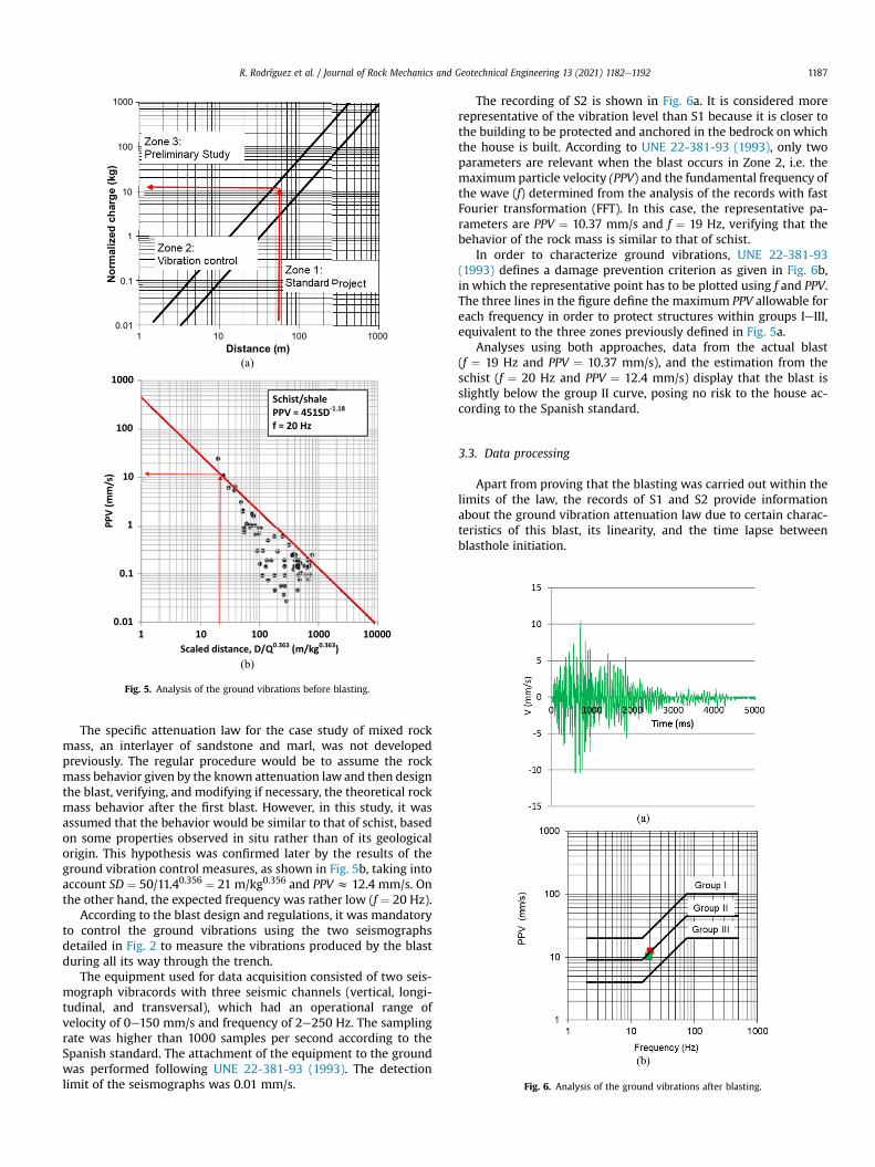
Fig. 5. Analysis of the ground vibrations before blasting.
Fig. 6. Analysis of the ground vibrations after blasting.
R. Rodríguez et al. / Journal of Rock Mechanics and Geotechnical Engineering 13 (2021) 1182e1192 1187
The specific attenuation law for the case study of mixed rockmass, an interlayer of sandstone and marl, was not developedpreviously. The regular procedure would be to assume the rockmass behavior given by the known attenuation law and then designthe blast, verifying, and modifying if necessary, the theoretical rockmass behavior after the first blast. However, in this study, it wasassumed that the behavior would be similar to that of schist, basedon some properties observed in situ rather than of its geologicalorigin. This hypothesis was confirmed later by the results of theground vibration control measures, as shown in Fig. 5b, taking intoaccount SD ¼ 50/11.40.356 ¼ 21 m/kg0.356 and PPV z 12.4 mm/s. Onthe other hand, the expected frequency was rather low (f ¼ 20 Hz).
According to the blast design and regulations, it was mandatoryto control the ground vibrations using the two seismographsdetailed in Fig. 2 to measure the vibrations produced by the blastduring all its way through the trench.
The equipment used for data acquisition consisted of two seis-mograph vibracords with three seismic channels (vertical, longi-tudinal, and transversal), which had an operational range ofvelocity of 0e150 mm/s and frequency of 2e250 Hz. The samplingrate was higher than 1000 samples per second according to theSpanish standard. The attachment of the equipment to the groundwas performed following UNE 22-381-93 (1993). The detectionlimit of the seismographs was 0.01 mm/s.
The recording of S2 is shown in Fig. 6a. It is considered morerepresentative of the vibration level than S1 because it is closer tothe building to be protected and anchored in the bedrock on whichthe house is built. According to UNE 22-381-93 (1993), only twoparameters are relevant when the blast occurs in Zone 2, i.e. themaximum particle velocity (PPV) and the fundamental frequency ofthe wave (f) determined from the analysis of the records with fastFourier transformation (FFT). In this case, the representative pa-rameters are PPV ¼ 10.37 mm/s and f ¼ 19 Hz, verifying that thebehavior of the rock mass is similar to that of schist.
In order to characterize ground vibrations, UNE 22-381-93(1993) defines a damage prevention criterion as given in Fig. 6b,in which the representative point has to be plotted using f and PPV.The three lines in the figure define the maximum PPV allowable foreach frequency in order to protect structures within groups IeIII,equivalent to the three zones previously defined in Fig. 5a.
Analyses using both approaches, data from the actual blast(f ¼ 19 Hz and PPV ¼ 10.37 mm/s), and the estimation from theschist (f ¼ 20 Hz and PPV ¼ 12.4 mm/s) display that the blast isslightly below the group II curve, posing no risk to the house ac-cording to the Spanish standard.
3.3. Data processing
Apart from proving that the blasting was carried out within thelimits of the law, the records of S1 and S2 provide informationabout the ground vibration attenuation law due to certain charac-teristics of this blast, its linearity, and the time lapse betweenblasthole initiation.

R. Rodríguez et al. / Journal of Rock Mechanics and Geotechnical Engineering 13 (2021) 1182e11921188
Data from the three directions of the blast, i.e. vertical, longi-tudinal, and transversal, were analyzed to determine the seismicwave attenuation. However, only the vertical component was usedin this study since the longitudinal and transversal componentsdepend very much on the propagation direction. Data from eachseismograph were extracted and processed to obtain the evolutionof the velocity with time. Figs. 7 and 8 display the vertical com-ponents from S1 attached to the soil and S2 attached to the bedrock,respectively. It was obtained that PPV ¼ 36.49 mm/s andPPV ¼ 10.37 mm/s for S1 and S2, respectively. The fundamentalfrequency determined by FFT analysis was f ¼ 19 Hz in both cases.
When the records in Figs. 7 and 8 are observed in detail, it can beseen that all the peaks correspond to the detonation of a pair ofblastholes, separated by approximately 42 m s, without the over-lapping of the wave between blastholes initiated at different times.This fact is easily verified by analyzing a small period of time. Figs. 9
Fig. 8. Record of the vertic
Fig. 7. Record of the vertic
Fig. 9. Partial record of the vertical com
and 10 show parts of the records from S1 and S2 between 2000 msand 3000 ms.
Based on the information obtained from the graphs, it could beconsidered, in terms of vibration, that many different blasts occurin the trench due to the time span between detonations (42 ms).Therefore, the record is formed by a group of separated blasts atdifferent distances from the seismographs, and this informationcan be used to define the transmissivity or attenuation law of thecase study. The PPV generated for each pair of blastholes in S1 andS2 is represented as a function of time in Fig.11a and b, respectively.
Similarly, the distance from the pair of blastholes detonated at agiven moment to S1 and S2 and the charge of these two blastholescan be expressed as a function of time (Fig. 12).
Subsequently, the transmissivity law can be calculated bycombining the data from the previous graphs, since PPV is related tothe maximum charge per delay and the distance between the
al component from S2.
al component from S1.
ponent from S1 in 2000e3000 ms.

Fig. 10. Partial record of the vertical component from S2 in 2000e3000 ms.
Fig. 11. Peak values registered by the seismographs (a) S1 and (b) S2.
Fig. 12. (a) Distance from the instantaneous blast to the seismographs and (b)instantaneous charge.
R. Rodríguez et al. / Journal of Rock Mechanics and Geotechnical Engineering 13 (2021) 1182e1192 1189
seismograph and the blasting face in each instance. As there is nogeneral transmissivity law for this type of rock mass, i.e. sandstoneandmarl from Purbeck facies, an adjustment of one of the statisticallaws developed by Balsa (1989) was considered.
It has to be pointed out that the distance from the detonatedblasthole to the seismographer varies in a relatively wide range,while the charge per delay is kept in a small range, between 10 kgand 15 kg in 80% of the cases, with an overall average value of 13 kg.This last value is used in the calculations in the following section.
4. Results and discussion
4.1. Ground vibration attenuation law
The maximum values of the peak velocity for each blastholefrom S1 (blue) and S2 (green) were used to obtain an empiricalequation from which the wave attenuation law depending on the
distance can be calculated (Fig. 13a). The full attenuation law wasobtained (blue line) using a single blast, which was a completelydifferent approach from the traditional method, where it isassumed that each blast can only provide a single point of theattenuation law. The representative points were compared toother already stablished attenuation laws to verify the results (redline).
The shape of the point cloud suggests that there is an importantcomponent of non-elastic energy loss. In this regard, Ghosh andDaemen (1983) and Rai and Sigh (2004) suggested expressions torepresent the decrease in PPV with distance. The approach fromGhosh and Daemen (1983) was considered most convenient for thecase study (see Eq. (8)), assuming that the reduced distance cor-responds to schist (SD ¼ D=Q0:365Þ, where the exponent, 0.365, isvery close to 1/3 (z0.333) as suggested by the authors.
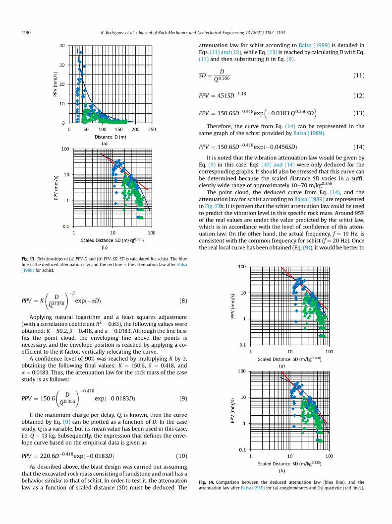
Fig. 13. Relationships of (a) PPV-D and (b) PPV-SD. SD is calculated for schist. The blueline is the deduced attenuation law and the red line is the attenuation law after Balsa(1989) for schist.
Fig. 14. Comparison between the deduced attenuation law (blue line), and theattenuation law after Balsa (1989) for (a) conglomerates and (b) quartzite (red lines).
R. Rodríguez et al. / Journal of Rock Mechanics and Geotechnical Engineering 13 (2021) 1182e11921190
PPV ¼ K
D
Q0:356
!�b
expð�aDÞ (8)
Applying natural logarithm and a least squares adjustment(with a correlation coefficient R2 ¼ 0.63), the following values wereobtained: K¼ 50.2, b¼ 0.418, and a¼ 0.0183. Although the line bestfits the point cloud, the enveloping line above the points isnecessary, and the envelope position is reached by applying a co-efficient to the K factor, vertically relocating the curve.
A confidence level of 90% was reached by multiplying K by 3,obtaining the following final values: K ¼ 150.6, b ¼ 0.418, anda ¼ 0.0183. Thus, the attenuation law for the rock mass of the casestudy is as follows:
PPV ¼ 150:6
D
Q0:356
!�0:418
expð�0:0183DÞ (9)
If the maximum charge per delay, Q, is known, then the curveobtained by Eq. (9) can be plotted as a function of D. In the casestudy, Q is a variable, but its mean value has been used in this case,i.e. Q ¼ 13 kg. Subsequently, the expression that defines the enve-lope curve based on the empirical data is given as
PPV ¼ 220:6D�0:418expð�0:0183DÞ (10)
As described above, the blast design was carried out assumingthat the excavated rockmass consisting of sandstone andmarl has abehavior similar to that of schist. In order to test it, the attenuationlaw as a function of scaled distance (SD) must be deduced. The
attenuation law for schist according to Balsa (1989) is detailed inEqs. (11) and (12), while Eq. (13) is reached by calculatingDwith Eq.(11) and then substituting it in Eq. (9).
SD ¼ DQ0:356 (11)
PPV ¼ 451SD�1:18 (12)
PPV ¼ 150:6SD�0:418exp��0:0183 Q0:356SD
�(13)
Therefore, the curve from Eq. (14) can be represented in thesame graph of the schist provided by Balsa (1989).
PPV ¼ 150:6SD�0:418expð�0:0456SDÞ (14)
It is noted that the vibration attenuation law would be given byEq. (9) in this case. Eqs. (10) and (14) were only deduced for thecorresponding graphs. It should also be stressed that this curve canbe determined because the scaled distance SD varies in a suffi-ciently wide range of approximately 10e70 m/kg0.356.
The point cloud, the deduced curve from Eq. (14), and theattenuation law for schist according to Balsa (1989) are representedin Fig. 13b. It is proven that the schist attenuation law could be usedto predict the vibration level in this specific rock mass. Around 95%of the real values are under the value predicted by the schist law,which is in accordance with the level of confidence of this atten-uation law. On the other hand, the actual frequency, f ¼ 19 Hz, isconsistent with the common frequency for schist (f ¼ 20 Hz). Oncethe real local curve has been obtained (Eq. (9)), it would be better to

Fig. 15. Comparison between the deduced attenuation law (blue line), and theattenuation law after Balsa (1989) for (a) gypsum and (b) limestone (red lines).
R. Rodríguez et al. / Journal of Rock Mechanics and Geotechnical Engineering 13 (2021) 1182e1192 1191
use it instead of other more general expressions, which is alsouseful for other parts of the trench and similar geomechanicalconditions.
4.2. Analysis with attenuation laws from other types of rock masses
It is interesting to compare the empirical attenuation law ob-tained in this study with other data and expressions from othertypes of rock masses gathered by Balsa (1989) that are commonlyblasted. As can be seen in Fig. 14, conglomerates and quartzite haveattenuation laws that could be used to predict the PPV in the casestudy. However, these are completely different rock masses,stronger than sandstone/marl interlayer. This can be deduced fromtheir natural frequencies, on average f ¼ 30 Hz for conglomerateand f ¼ 40 Hz for quartzite.
On the contrary, rock masses with typically low natural fre-quencies, similar to those observed in this study, such as gypsumwith an average of f ¼ 10 Hz or limestone with f ¼ 25 Hz, havedifferent behaviors regarding the PPV attenuation. The gypsum andlimestone attenuation laws predict PPV values several times higherthan the real ones, 5e10 times in the case of gypsum and 2e4 timesin the case of limestone (Fig. 15).
The behavior of these four types of rocks (conglomerate,quartzite, gypsum, and limestone), although similar in some as-pects, cannot be assumed to be equivalent to the real behavior ofthe sandstone/marl interlayer studied. Only the schist displayedequivalent characteristics compared to sandstone/marl interlayer,as its attenuation law can be used to predict the PPV and the naturalfrequency of the vibration. This similarity is based on similar
geomechanical properties, regardless of the nature of the rock or itsgenesis, as stated by Sambuelli (2009) and Kumar et al. (2016).
5. Conclusions
In this study, an approach to define the transmissivity laws forground vibrations in a single blast was determined. However, theresults cannot be generalized, allowing the use of this approachonly in the specific area of the case study.
The blast behavior was defined, as thewave approaches, reachesthe peak vibration value, and starts decreasing as it moves furthersaway. This information, together with the minimum distance fromthe measuring point to the trace and the explosive charge, can beused to calculate all the necessary empirical relationships. A pro-cedure to determine and validate an approximation of the behaviorof rock masses with the general transmissivity laws wasestablished.
This methodology can be used as guidance in other cases, takinga step forward towards simpler and faster preliminary studieswhere explosives are required, being able to control the frequencyand PPV according to national regulations. This would decrease thecosts of the preliminary and control studies.
Although the general law proposed cannot substitute for aspecific analysis of a case study, it provides a very reliableapproximation, avoiding previous studies required by the govern-mental authority in some cases.
Declaration of competing interest
The authors declare that they have no known competingfinancial interests or personal relationships that could haveappeared to influence the work reported in this paper.
Acknowledgments
The present work was partially funded by Perforaciones Nor-oeste S.A. in the frame of the University-Company collaborationproject FUO-068-17.
References
Agrawal, H., Mishra, A.K., 2019. Modified scaled distance regression analysisapproach for prediction of blast-induced ground vibration in multi-holeblasting. J. Rock Mech. Geotech. Eng. 11 (1), 202e207.
Ak, H., Konuk, A., 2008. The effect of discontinuity frequency on ground vibrationsproduced from bench blasting: a case study. Soil Dynam. Earthq. Eng. 28 (9),686e694.
Aldas, G.G.U., 2010. Investigation of blast design parameters from the point ofseismic signals. Int. J. Min. Reclamat. Environ. 24 (1), 80e90.
Álvarez-Vigil, A.E., González-Nicieza, C., Gayarre, F.L., Álvarez-Fernández, M.I., 2012.Predicting blasting propagation velocity and vibration frequency using artificialneural networks. Int. J. Rock Mech. Min. Sci. 55, 108e116.
Ambraseys, N.R., Hendron, A.J., 1968. Dynamic behavior of rock masses: rock me-chanics in engineering practices. In: Stagg, K., Wiley, J. (Eds.), Rock Mechanics inEngineering Practices. Wiley, London, UK, pp. 203e207.
Balsa, P.J., 1989. Leyes estadísticas de transmisividad en distintos tipos de rocas.Canteras Explot. (272), 61e73 (in Spanish).
Blair, B.E., Duvall, W.I., 1954. In: Evaluation of Gages for Measuring Displacement,Velocity and Acceleration of Seismic Pulses. USBM Report 5073. U.S. Bureau ofMines (USBM), Washington, D.C., USA.
Blair, D.P., Armstrong, L.W., 1999. The spectral control of ground vibration usingelectronic delay detonators. Fragblast 3 (4), 303e334.
Crandell, F.J., 1949. Ground vibration due to blasting and its effects upon structures.J. Boston Soc. Civil Eng. 3, 222e245.
De Cospedal, J., 2019. Utilización de la medida de vibraciones en voladuras para elconocimiento de los daños al macizo de roca ornamental. PhD Thesis. Uni-versidad Politécnica de Cartagena, Cartagena, Spain (in Spanish).
Devine, J.R., 1966. Avoiding damage to residences from blasting vibrations. Highw.Res. Rec. (135), 35e42.
Dowding, C.H., 1971. Response of Building to Ground Vibrations Resulting fromConstruction Blasting. PhD Thesis. University of Illinois Urbana-Champaign,USA.

R. Rodríguez et al. / Journal of Rock Mechanics and Geotechnical Engineering 13 (2021) 1182e11921192
Ghosh, A., Daemen, J.K., 1983. A simple new blast vibration predictor. In: Pro-ceedings of the 24th U.S. Symposium of Rock Mechanics. Association of Engi-neering Geologists (AEG), Brunswick, USA, pp. 151e161.
Hemant, A., Mishra, A.K., 2019. An innovative technique of simplified signature holeanalysis for prediction of blast-induced ground vibration of multi-hole/production blast: an empirical analysis. Nat. Hazards 100, 111e132.
Holmberg, R., Persson, P.A., 1978. The Swedish approach to contour blasting. In:Proceedings of Conference on Explosives and Blasting Technique. Society ofExplosives Engineers, New Orleans, pp. 113e127.
Hudaverdi, T., 2012. Application of multivariate analysis for prediction of blast-induced ground vibrations. Soil Dynam. Earthq. Eng. 43, 300e308.
Iramina, W.S., Sansone, E.C., Wichers, M., Wahyudi, S., Eston, S.M.D., Shimada, H.,Sasaoka, T., 2018. Comparing blast-induced ground vibration models using ANNand empirical geomechanical relationships. REM Int. Eng. J. 71 (1), 89e95.
Jayasinghe, B., Zhao, Z., Teck Chee, A.G., Zhou, H., Gui, Y., 2019. Attenuation of rockblasting induced ground vibration in rock-soil interface. J. Rock Mech. Geotech.Eng. 11 (4), 770e778.
Khandelwal, M., Saadat, M., 2015. A dimensional analysis approach to study blast-induced ground vibration. Rock Mech. Rock Eng. 48 (2), 727e735.
Khandelwal, M., Singh, T.N., 2009. Prediction of blast-induced ground vibrationusing artificial neural network. Int. J. Rock Mech. Min. Sci. 46 (7), 1214e1222.
Konon, W., 1985. Vibration criteria for historic buildings. J. Construct. Eng. Manag.111, 208e215.
Kumar, R., Choudhury, D., Bhargava, K., 2016. Determination of blast-inducedground vibration equations for rocks using mechanical and geological proper-ties. J. Rock Mech. Geotech. Eng. 8 (3), 341e349.
Kuzu, C., 2008. The importance of site-specific characters in prediction models forblast-induced ground vibrations. Soil Dynam. Earthq. Eng. 28 (5), 405e414.
Langefors, U., Kihlstrom, B., 1978. The Modern Technique of Rock Blasting, third ed.John Wiley & Sons Inc., New York, USA.
López-Jimeno, C., López-Jimeno, E., Bermúdez, P.G., 2017. Manual de perforación,explosivos y voladuras: Minería y obras públicas. Universidad Politécnica deMadrid, Grupo de Proyectos de Ingeniería, Madrid, Spain (in Spanish).
Mesec, J., Kova�c, I., Soldo, B., 2010. Estimation of particle velocity based on blastevent measurements at different rock units. Soil Dynam. Earthq. Eng. 30 (10),1004e1009.
Monjezi, M., Hasanipanah, M., Khandelwal, M., 2013. Evaluation and prediction ofblast-induced ground vibration at Shur River Dam, Iran, by artificial neuralnetwork. Neural Comput. Appl. 22 (7e8), 1637e1643.
Morris, G., 1950. Vibrations Due to Blasting and Their Effects on Building Structure.The Engineer, London, UK.
Nateghi, R., 2011. Prediction of ground vibration level induced by blasting atdifferent rock units. Int. J. Rock Mech. Min. Sci. 48 (6), 899e908.
Nicholls, H.R., Johnson, C.F., Duvall, W.I., 1971. Blasting Vibrations and Their Effectson Structures. U.S. Department of the Interior, Washington, D.C., USA.
Ozer, U., 2008. Environmental impacts of ground vibration induced by blasting atdifferent rock units on the KadikoyeKartal metro tunnel. Eng. Geol. 100 (1e2),82e90.
Rai, R., Singh, T., 2004. A new predictor for ground vibration prediction and itscomparison with other predictors. Indian J. Eng. Mater. Sci. 11 (3), 178e184.
Richards, A.B., 2008. Blast vibration wavefront reinforcement model. Min. Technol.117 (4), 161e167.
Rockwell, E.H., 1927. Vibrations caused by quarry blasting and their effects onstructures. Rock Prod. 30, 51e61.
Sambuelli, L., 2009. Theoretical derivation of a peak particle velocityedistance lawfor the prediction of vibrations from blasting. Rock Mech. Rock Eng. 42, 547e556.
Schexnayder, C.J., Ernzen, J.E., 1999. Mitigation of Night-Time Construction Noise,Vibration, and Other Nuisances. National Academy Press, Washington, D.C.,USA.
Shao, S., Petrovitch, C.L., Pyrak-Nolte, L.J., 2015. Wave guiding in fractured layeredmedia. In: Agar, S.M., Geiger, S. (Eds.), Fundamental Controls on Fluid Flow inCarbonates: Current Workflows to Emerging Technologies. The Geological So-ciety of London, London, UK, pp. 375e400.
Singh, P., Narendrula, R., 2007. The influence of rock mass quality in controlledblasting. In: Proceedings of the 26th International Conference on GroundControl in Mining. Lakeview Scanticon Resort & Conference Center, Morgan-town, WV, USA, pp. 314e319.
Singh, P.K., Vogt, W., 1998. Effect of total explosives fired in a blasting round on blastvibration. Coal Int. 246 (1), 20e22.
Studer, J., Suesstrunk, A., 1981. Swiss standard for vibration damage to buildings. In:Proceedings of the 10th International Conference on Soil Mechanics andFoundation Engineering. International Federation for Structural Concrete,Stockholm, Sweden.
Stump, B.W., Reinke, R.E., 1983. Experimental confirmation of superposition fromsmall-scale explosions. Bull. Seismol. Soc. Am. 78, 1059e1073.
Takahashi, Y., Sasaoka, T., Sugeng, W., Hamanaka, A., Shimada, H., Saburi, T.,Kubota, S., 2018. Study on prediction of ground vibration in consideration ofdamping effect by fragment in the rock mass. J. Geosci. Environ. Protect. 6 (6),1e11.
Toraño, J., Ramírez-Oyanguren, P., Rodríguez, R., Diego, I., 2006. Analysis of theenvironment effects of ground vibrations produced by blasting in quarries. Int.J. Min. Reclamat. Environ. 20 (4), 249e266.
Tripathy, G.R., Shirke, R.R., Kudale, M.D., 2016. Safety of engineered structuresagainst blast vibrations: a case study. J. Rock Mech. Geotech. Eng. 8 (2), 248e255.
Tsiambaos, G., Saroglou, H., 2010. Excavatability assessment of rock masses usingthe geological strength index (GSI). Bull. Eng. Geol. Environ. 69, 13e27.
UNE 22-381-93, 1993. Control of Vibrations Caused by Blasting. Spanish Associationfor Standardisation (UNE), Madrid, Spain (in Spanish).
Wu, Y.K., Hao, H., Zhou, Y.X., Chong, K., 1998. Propagation characteristics of blast-induced shock waves in a jointed rock mass. Soil Dynam. Earthq. Eng. 17 (6),407e412.
Yan, Y., Hou, X., Fei, H., 2020. Review of predicting the blast-induced ground vi-brations to reduce impacts on ambient urban communities. J. Clean. Prod. 260,121135.
Yu, Z., Shi, X., Zhou, J., Gou, Y., Huo, X., Zhang, J., Armaghani, D.J., 2020. A newmultikernel relevance vector machine based on the HPSOGWO algorithm forpredicting and controlling blast-induced ground vibration. Eng. Comput.https://doi.org/10.1007/s00366-020-01136-2.
Zhou, J., Asteris, P.G., Armaghani, D.J., Pham, B.T., 2020. Prediction of ground vi-bration induced by blasting operations through the use of the BayesianNetwork and random forest models. Soil Dynam. Earthq. Eng. 139, 106390.
Zhou, J., Li, C., Koopialipoor, M., Jahed Armaghani, D., Thai Pham, B., 2021. Devel-opment of a new methodology for estimating the amount of PPV in surfacemines based on prediction and probabilistic models (GEP-MC). Int. J. Min.Reclamat. Environ. 35 (1), 48e68.