developed by: u.s. epa/semarnap pollution prevention work...
TRANSCRIPT
POLLUTION PREVENTION IN THE ELECTRONICS INDUSTRY
DEVELOPED BY:
U.S. EPA/SEMARNAPPOLLUTION PREVENTIONWORK GROUP
MAY 1996

********************************&&&&&&&&&&&&&&&&&&&&&&&&&&&&&&&&&&&&&&&&&&&&&&&&&&&&&&&&&&&&&&&&&&&&&&&&&&&&&&&&&&&&&&&&&&&&
i
&&&&&&&&&&&&&&&&&&&&&&&&&&&&&&&&&&&&&&&&&&&&&&&&&&&&&&&&&&&&&&&&&&&&&&&&&&&&&&&&&&&&&&&&&&&&********************************
ii Pollution Prevention in the Electronics Industry
CONTENTS
Sheet 1 of 2
Section Page
LIMITATIONS OF THIS MANUAL . . . . . . . . . . . . . . . . . . . . . . . . . . . . . . . . . . . . . . . . . . . . . . . . . . . . . . v
INTRODUCTION . . . . . . . . . . . . . . . . . . . . . . . . . . . . . . . . . . . . . . . . . . . . . . . . . . . . . . . . . . . . . . . . . . . . . . vi
SECTION I GOALS AND BENEFITS OF POLLUTION PREVENTION . . . . . . . . . . . . . . . . . . . . . I-1
What is Pollution Prevention? . . . . . . . . . . . . . . . . . . . . . . . . . . . . . . . . . . . . . . . . . . . . . . . . . . . . . . I-1Pollution Prevention Goals . . . . . . . . . . . . . . . . . . . . . . . . . . . . . . . . . . . . . . . . . . . . . . . . . . . . . . . . I-4Benefits of a Pollution Prevention Program . . . . . . . . . . . . . . . . . . . . . . . . . . . . . . . . . . . . . . . . . . . I-4Developing a Pollution Prevention Program . . . . . . . . . . . . . . . . . . . . . . . . . . . . . . . . . . . . . . . . . . . I-8
SECTION II POLLUTION PREVENTION IN THE ELECTRONICS INDUSTRY . . . . . . . . . . . . . . II-1
Chapter 1 General Pollution Prevention Methods and Common Practices . . . . . . . . . . . . . II-2Chapter 2 The Microelectronics Industry . . . . . . . . . . . . . . . . . . . . . . . . . . . . . . . . . . . . . . . II-8
! Microelectronic Products . . . . . . . . . . . . . . . . . . . . . . . . . . . . . . . . . . . . . . . . . . . II-8! Processes and Typical Waste Streams . . . . . . . . . . . . . . . . . . . . . . . . . . . . . . . . . II-9! Pollution Prevention Options for the Microelectronics Industry . . . . . . . . . . . . II-15
Chapter 3 The Macroelectronics Industry . . . . . . . . . . . . . . . . . . . . . . . . . . . . . . . . . . . . . . II-35
! Macroelectronic Products . . . . . . . . . . . . . . . . . . . . . . . . . . . . . . . . . . . . . . . . . . II-35! Processes and Typical Waste Streams . . . . . . . . . . . . . . . . . . . . . . . . . . . . . . . . II-35! Pollution Prevention Options for the Macroelectronics Industry . . . . . . . . . . . . II-42
Bibliography . . . . . . . . . . . . . . . . . . . . . . . . . . . . . . . . . . . . . . . . . . . . . . . . . . . . . . . . . . . . . . . . . . II-60
SECTION III CASE STUDIES
CASE STUDY NO. 1—Printed Circuit Board Manufacturer . . . . . . . . . . . . . . . . . . . . . . . . . . . . III-1CASE STUDY NO. 2—Copper Recovery . . . . . . . . . . . . . . . . . . . . . . . . . . . . . . . . . . . . . . . . . . . III-3CASE STUDY NO. 3—Water Use Reduction . . . . . . . . . . . . . . . . . . . . . . . . . . . . . . . . . . . . . . . . III-4CASE STUDY NO. 4—Recovery of Metals . . . . . . . . . . . . . . . . . . . . . . . . . . . . . . . . . . . . . . . . . III-5CASE STUDY NO. 5—Reduction in Chemical Usage . . . . . . . . . . . . . . . . . . . . . . . . . . . . . . . . . III-6CASE STUDY NO. 6—Printed Circuit Board Manufacturer . . . . . . . . . . . . . . . . . . . . . . . . . . . . III-7CASE STUDY NO. 7—Semiconductor Manufacturer . . . . . . . . . . . . . . . . . . . . . . . . . . . . . . . . . . III-9

********************************&&&&&&&&&&&&&&&&&&&&&&&&&&&&&&&&&&&&&&&&&&&&&&&&&&&&&&&&&&&&&&&&&&&&&&&&&&&&&&&&&&&&&&&&&&&&
iiiCONTENTS
CASE STUDY NO. 8—Process Redesign and Recycling . . . . . . . . . . . . . . . . . . . . . . . . . . . . . III-10
&&&&&&&&&&&&&&&&&&&&&&&&&&&&&&&&&&&&&&&&&&&&&&&&&&&&&&&&&&&&&&&&&&&&&&&&&&&&&&&&&&&&&&&&&&&&********************************
iv Pollution Prevention in the Electronics Industry
CONTENTS
Sheet 2 of 2
Section Page
CASE STUDY NO. 9—Chemical Substitution, Process Redesign, and Resource Conservation . . . . . . . . . . . . . . . . . . . . . . . . . . . . . . . . . . . . . . . . . . . III-11
CASE STUDY NO. 10—Maquiladora Success Story . . . . . . . . . . . . . . . . . . . . . . . . . . . . . . . . III-12CASE STUDY NO. 11—Manufacturer of DC Electric Motors . . . . . . . . . . . . . . . . . . . . . . . . . III-13CASE STUDY NO. 12—Electronics Manufacturer . . . . . . . . . . . . . . . . . . . . . . . . . . . . . . . . . . III-14CASE STUDY NO. 13—Ultrasonic Cleaning . . . . . . . . . . . . . . . . . . . . . . . . . . . . . . . . . . . . . . III-16CASE STUDY NO. 14—Weapons Systems Manufacturer . . . . . . . . . . . . . . . . . . . . . . . . . . . . III-17
Appendix
ADDITIONAL INFORMATION
Attachments
A INFORMATION ON ACCESSING POLLUTION PREVENTION INFORMATIONCLEARINGHOUSES
B SURVEY

********************************&&&&&&&&&&&&&&&&&&&&&&&&&&&&&&&&&&&&&&&&&&&&&&&&&&&&&&&&&&&&&&&&&&&&&&&&&&&&&&&&&&&&&&&&&&&&
vCONTENTS
FIGURES
Figure Page
I-1 WASTE MANAGEMENT HIERARCHY . . . . . . . . . . . . . . . . . . . . . . . . . . . . . . . . . . . . . . . . . . . . I-5
I-2 POLLUTION PREVENTION PROGRAM . . . . . . . . . . . . . . . . . . . . . . . . . . . . . . . . . . . . . . . . . . I-10
II-1 PRINTED CIRCUIT BOARD PRODUCTION PROCESS . . . . . . . . . . . . . . . . . . . . . . . . . . . . II-10
II-2 SEMICONDUCTOR PRODUCTION PROCESS . . . . . . . . . . . . . . . . . . . . . . . . . . . . . . . . . . . . II-12
II-3 CONFIGURATION OF AQUEOUS CLEANING PROCESS . . . . . . . . . . . . . . . . . . . . . . . . . . II-19
II-4 ENCLOSED SEMIAQUEOUS CLEANING PROCESS . . . . . . . . . . . . . . . . . . . . . . . . . . . . . . II-21
II-5 SCHEMATIC DIAGRAM OF SEMIAQUEOUS SPRAY EQUIPMENT . . . . . . . . . . . . . . . . . II-22
II-6 AUTOMATED AQUEOUS ROTARY WASHING PROCESS . . . . . . . . . . . . . . . . . . . . . . . . . II-26
II-7 HOW ULTRASONICS WORK TO CLEAN A SURFACE . . . . . . . . . . . . . . . . . . . . . . . . . . . . II-45
II-8 BATCH ULTRASONIC CLEANING TANK . . . . . . . . . . . . . . . . . . . . . . . . . . . . . . . . . . . . . . . II-46
II-9 SUPERCRITICAL CARBON DIOXIDE CLEANING SYSTEM . . . . . . . . . . . . . . . . . . . . . . . II-50
II-10 LOW-EMISSION VAPOR DEGREASER . . . . . . . . . . . . . . . . . . . . . . . . . . . . . . . . . . . . . . . . . II-53
TABLES
Table Page
I-1 EXAMPLES OF SOURCE REDUCTION OPPORTUNITIES . . . . . . . . . . . . . . . . . . . . . . . . . . . I-2
I-2 WASTE MANAGEMENT STRATEGIES THAT ARE NOT POLLUTIONPREVENTION . . . . . . . . . . . . . . . . . . . . . . . . . . . . . . . . . . . . . . . . . . . . . . . . . . . . . . . . . . . . . . . . . I-3
II-1 TYPICAL WASTES GENERATED IN THE MICROELECTRONICS INDUSTRY . . . . . . . . II-13
II-2 TYPICAL WASTES GENERATED IN THE MACROELECTRONICS INDUSTRY . . . . . . . II-40
&&&&&&&&&&&&&&&&&&&&&&&&&&&&&&&&&&&&&&&&&&&&&&&&&&&&&&&&&&&&&&&&&&&&&&&&&&&&&&&&&&&&&&&&&&&&********************************
vi Pollution Prevention in the Electronics Industry
LIMITATIONS OF THIS MANUAL
This manual provides an overview of the pollution prevention and recycling alternatives that areavailable in the electronics industry. This report is intended only to assist the user in his or herpreliminary research and development of pollution prevention options. Each company is responsible foridentifying, evaluating, and implementing pollution prevention practices that are appropriate to itsspecific situation. By compiling and distributing this manual, EPA and SEMARNAP are notrecommending the use of any particular processes, raw materials, products, or techniques in anyparticular industrial setting. Compliance with U.S. and Mexican environmental laws, occupational healthand safety laws, and all applicable federal, state, and local laws and regulations is the responsibility ofeach individual business. It is not the focus of this document.
The information in this manual is intended to be a relatively comprehensive overview of the documentedinformation on pollution prevention and recycling practices for the electronics industry. However, thecollection, organization, and dissemination of pollution prevention information is a relatively newinitiative, and an ongoing and evolutionary process. In addition, there are limits to any manual, includingthis one. Therefore, this summary may not contain every relevant piece of information on pollutionprevention and recycling for electronics companies. EPA encourages all users—who discover, in theliterature or in the field, pollution prevention options that are not cited in this report—to share thisinformation with EPA. Please submit any corrections, updates, or comments on this report to thefollowing:
Robert D. Lawrence (6EN-XP)Pollution Prevention CoordinatorU.S. EPA Region 61445 Ross AvenueDallas, TX 75202(214) 665-2258
This manual is an assimilation of existing research and case studies of waste minimization and pollutionprevention principles. Because of the voluminous amount of such information, referencing sources inthe text as and when they are used would make the manual cumbersome for the reader. Therefore, theauthors of this manual wish to acknowledge the authors of all of the documents referenced throughoutthe text and listed in the bibliography section.
********************************&&&&&&&&&&&&&&&&&&&&&&&&&&&&&&&&&&&&&&&&&&&&&&&&&&&&&&&&&&&&&&&&&&&&&&&&&&&&&&&&&&&&&&&&&&&&
viiINTRODUCTION
INTRODUCTION
The production of economically competitive products is the driving force behind any successful business.Production frequently requires the use of various chemicals throughout the manufacturing process. Thepurchase and storage of these chemicals, their use in the process, and the ultimate disposal of the wastegenerated by the manufacturing process can present many problems. These problems include financialconcerns, environmental management, and worker health and safety. Pollution prevention provides aneffective means to minimize, and even eliminate, such problems.
The U.S. Environmental Protection Agency (EPA) defines pollution prevention (also referred toas source reduction) as the use of materials, processes, or practices that reduce or eliminate thegeneration of pollutants or wastes at the source. It includes practices that reduce the use of hazardousand nonhazardous materials, energy, water, and other resources, in addition to practices that protectnatural resources through conservation or more efficient use.
Because of the enormous potential for pollution prevention along the U.S.-Mexico border, the PollutionPrevention Work Group was established in February 1992. The lead federal agencies of the Work Groupare EPA and Secretaria Del Medio Ambiente Recursos Naturales y Pesca (SEMARNAP). EPA andSEMARNAP also began promoting and coordinating the reduction of pollution through a broad rangeof approaches: technical assistance, training, public and private sector programs in pollution preventionawareness, assessment of pollution prevention opportunities, policy development and institutionalsupport, and technology development and investment activities.
The purpose of this manual is to provide pollution prevention information for the electronicsindustry. This manual builds on the efforts of the first two manuals —"Waste Minimization for theMetal Finishing Industry" and "Pollution Prevention for the Wood Finishing Industry." These manualswere the first and second in this series of bilingual pollution prevention manuals prepared jointly by EPAand SEMARNAP. Future manuals will include other industries that are typical in the border area. Thismanual contains the following sections:
Section I Goals and Benefits of Pollution Prevention
This introduction defines the term "pollution prevention," and provides an overview of the goals andbenefits of, as well as methods for developing, a successful pollution prevention program.
Section II Pollution Prevention in the Electronics Industry
This technical section describes various processes and waste streams associated with the electronicsindustry and pollution prevention options for that industry.
Section III Case Studies
This section includes specific examples of companies that have used pollution prevention techniques.These case studies describe the benefits, particularly cost savings, that these companies have derived.
Appendix Additional Information
&&&&&&&&&&&&&&&&&&&&&&&&&&&&&&&&&&&&&&&&&&&&&&&&&&&&&&&&&&&&&&&&&&&&&&&&&&&&&&&&&&&&&&&&&&&&********************************
viii Pollution Prevention in the Electronics Industry
This section lists additional technical documents pertaining to pollution prevention opportunities for theelectronics industry, and other pertinent information. These documents are currently available only inEnglish.
Attachment A Information on Accessing Pollution PreventionInformation Clearinghouses
Attachment B Survey
PLEASE COMPLETE THE SURVEY INCLUDED IN THIS SECTION. Your response providesvaluable information for evaluating the usefulness of this manual. Additionally, when your survey isreturned, your name will be placed on a mailing list for updates to the manual and other documents asthey become available.

Section I
Goals and Benefitsof Pollution Prevention

&&&&&&&&&&&&&&&&&&&&&&&&&&&&&&&&&&&&&&&&&&&&&&&&&&&&&&&&&&&&&&&&&&&&&&&&&&&&&&&&&&&&&&&&&&&&********************************
I-1GOALS AND BENEFITS OF POLLUTION PREVENTION
GOALS AND BENEFITS OF POLLUTION PREVENTION
WHAT IS POLLUTION PREVENTION?
As defined by EPA, pollution prevention (also known as source reduction) is the act of eliminating the pollutantbefore it is generated. The idea is to prevent the generation of pollution rather than determine what to do(pollution control or waste management) once it is generated. Technically, pollution prevention is a managementtool that prevents or reduces pollution at the source through cost-effective changes in production, design, andoperation. It includes practices that reduce the use of hazardous and nonhazardous materials, energy, water, andother resources, in addition to practices that protect natural resources through conservation or more efficient use.Such changes offer industry substantial savings in reduced raw materials, pollution control, and liability costs,as well as, help protect the environment and reduce risks to worker health and safety.
Moreover, pollution prevention is more than just another way to reduce pollution. Pollution prevention is a mind-set. This mind-set continually searches for innovative ways to do things better and to overcome the inherenthuman resistance to change. Such a mind-set does not accept "that is how we have always done it" as a reasonfor maintaining a policy or practice.
Source reduction eliminates the pollutant before it is generated. Source reduction opportunities includethe following:
! Material changes that substitute less hazardous input materials for process chemicals thatgenerate hazardous waste.
! Change the process design and incorporate current technologies that increase efficiency andreduce or eliminate the amount of pollutants being generated.
! Improve operating practices that promote reuse and recycling over disposal, good inventorycontrol to eliminate the accumulation of unused or expired chemicals, and proper maintenanceto prevent leaks and spills.
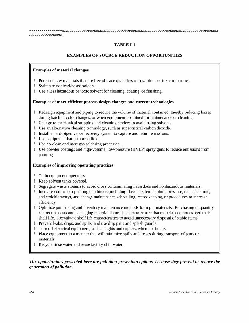
Table I-1 summarizes specific examples of source reduction opportunities.
Other Environmental Management Strategies
There are numerous pollution control or waste management strategies that are applied only after wasteshave been generated, instead of preventing the generation of a pollutant. Therefore, they are not correctlycategorized as pollution prevention. Table I-2 provides examples of waste management strategies thatare not categorized as pollution prevention.
********************************&&&&&&&&&&&&&&&&&&&&&&&&&&&&&&&&&&&&&&&&&&&&&&&&&&&&&&&&&&&&&&&&&&&&&&&&&&&&&&&&&&&&&&&&&&&&
I-2 Pollution Prevention in the Electronics Industry
TABLE I-1
EXAMPLES OF SOURCE REDUCTION OPPORTUNITIES
Examples of material changes
! Purchase raw materials that are free of trace quantities of hazardous or toxic impurities. ! Switch to nonlead-based solders. ! Use a less hazardous or toxic solvent for cleaning, coating, or finishing.
Examples of more efficient process design changes and current technologies
! Redesign equipment and piping to reduce the volume of material contained, thereby reducing lossesduring batch or color changes, or when equipment is drained for maintenance or cleaning.
! Change to mechanical stripping and cleaning devices to avoid using solvents. ! Use an alternative cleaning technology, such as supercritical carbon dioxide. ! Install a hard-piped vapor recovery system to capture and return emissions. ! Use equipment that is more efficient. ! Use no-clean and inert gas soldering processes. ! Use powder coatings and high-volume, low-pressure (HVLP) spray guns to reduce emissions from
painting.
Examples of improving operating practices
! Train equipment operators. ! Keep solvent tanks covered. ! Segregate waste streams to avoid cross contaminating hazardous and nonhazardous materials. ! Increase control of operating conditions (including flow rate, temperature, pressure, residence time,
and stoichiometry), and change maintenance scheduling, recordkeeping, or procedures to increaseefficiency.
! Optimize purchasing and inventory maintenance methods for input materials. Purchasing in quantitycan reduce costs and packaging material if care is taken to ensure that materials do not exceed theirshelf life. Reevaluate shelf life characteristics to avoid unnecessary disposal of stable items.
! Prevent leaks, drips, and spills, and use drip pans and splash guards. ! Turn off electrical equipment, such as lights and copiers, when not in use. ! Place equipment in a manner that will minimize spills and losses during transport of parts or
materials. ! Recycle rinse water and reuse facility chill water.
The opportunities presented here are pollution prevention options, because they prevent or reduce thegeneration of pollution.
&&&&&&&&&&&&&&&&&&&&&&&&&&&&&&&&&&&&&&&&&&&&&&&&&&&&&&&&&&&&&&&&&&&&&&&&&&&&&&&&&&&&&&&&&&&&********************************
I-3GOALS AND BENEFITS OF POLLUTION PREVENTION
TABLE I-2
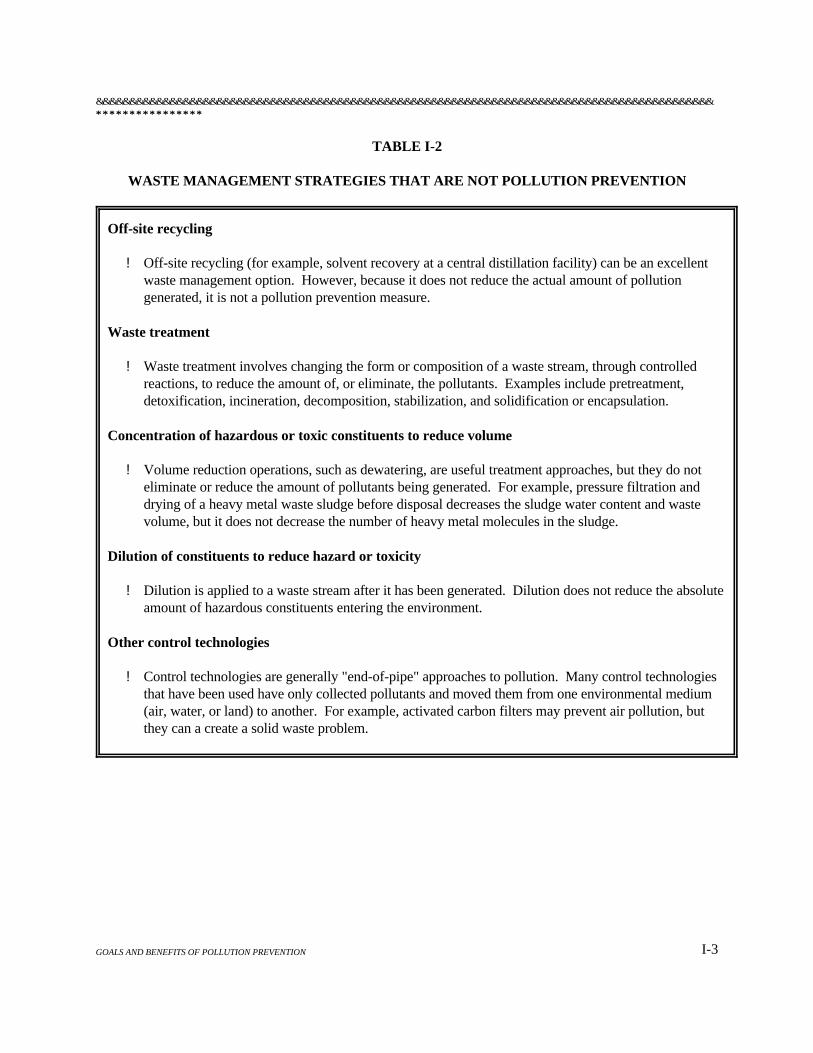
WASTE MANAGEMENT STRATEGIES THAT ARE NOT POLLUTION PREVENTION
Off-site recycling
! Off-site recycling (for example, solvent recovery at a central distillation facility) can be an excellentwaste management option. However, because it does not reduce the actual amount of pollutiongenerated, it is not a pollution prevention measure.
Waste treatment
! Waste treatment involves changing the form or composition of a waste stream, through controlledreactions, to reduce the amount of, or eliminate, the pollutants. Examples include pretreatment,detoxification, incineration, decomposition, stabilization, and solidification or encapsulation.
Concentration of hazardous or toxic constituents to reduce volume
! Volume reduction operations, such as dewatering, are useful treatment approaches, but they do noteliminate or reduce the amount of pollutants being generated. For example, pressure filtration anddrying of a heavy metal waste sludge before disposal decreases the sludge water content and wastevolume, but it does not decrease the number of heavy metal molecules in the sludge.
Dilution of constituents to reduce hazard or toxicity
! Dilution is applied to a waste stream after it has been generated. Dilution does not reduce the absoluteamount of hazardous constituents entering the environment.
Other control technologies
! Control technologies are generally "end-of-pipe" approaches to pollution. Many control technologiesthat have been used have only collected pollutants and moved them from one environmental medium(air, water, or land) to another. For example, activated carbon filters may prevent air pollution, butthey can a create a solid waste problem.
********************************&&&&&&&&&&&&&&&&&&&&&&&&&&&&&&&&&&&&&&&&&&&&&&&&&&&&&&&&&&&&&&&&&&&&&&&&&&&&&&&&&&&&&&&&&&&&
I-4 Pollution Prevention in the Electronics Industry
Many waste management practices used to date have merely collected pollutants and moved them fromone environmental medium to another. Companies should recognize that transferring hazardous wastesto another environmental medium is not pollution prevention. For example, solvents can be removedfrom wastewater by using activated carbon. However, regenerating the activated carbon requires usinganother solvent or heating, which transfers the contaminants to the air. In some cases, this type of wastemanagement strategy is a valid treatment option. However, too often the result has been to shift apollutant to a medium that is regulated less stringently.
For example, waste treatment prior to disposal reduces the toxicity and/or disposal-site spacerequirements but does not eliminate all pollutant materials. Frequently, the effect is to transfer pollutionfrom air or water to land. Conventional waste treatments include processes such as volume reduction,dilution, detoxification, incineration, and stabilization.
Off-site recycling, which is another waste management strategy, is vastly preferable to other forms ofoff-site waste handling, because it helps to preserve raw materials and reduce the amount of material thatwill require disposal. However, off-site recycling is likely to have more residual waste that requiresdisposal than closed-loop recycling (reuse) performed at the production site. Furthermore, wastetransportation and the off-site recycling process increase the risk of worker exposure and release to theenvironment.
The waste management hierarchy, represented on Figure I-1, prioritizes true pollution prevention options(source reduction and recycling reuse) over pollution control measures (treatment and disposal), in order,from the most environmentally beneficial to the least environmentally beneficial. Specific technicalinformation on pollution prevention options for the electronics industry is contained in Section II of thismanual.
POLLUTION PREVENTION GOALS
The goal of a pollution prevention program is to improve the quality of the environment by eliminatingor reducing the generation of waste at the source. Pollution prevention includes any action by a companyto reduce the amount of waste generated by a manufacturing process prior to off-site recycling, treatment,or disposal of the waste. To effectively accomplish this, the program must include an ongoing,comprehensive assessment of the operations at a facility.
BENEFITS OF A POLLUTION PREVENTION PROGRAM
Businesses and governments have strong incentives to reduce the toxicity and volume of the waste thatthey generate. As pollution prevention activities lower operating costs, production costs willdecrease. Therefore, companies with an effective, ongoing pollution prevention program will havea significant competitive advantage.

&&&&&&&&&&&&&&&&&&&&&&&&&&&&&&&&&&&&&&&&&&&&&&&&&&&&&&&&&&&&&&&&&&&&&&&&&&&&&&&&&&&&&&&&&&&&********************************
I-5GOALS AND BENEFITS OF POLLUTION PREVENTION
********************************&&&&&&&&&&&&&&&&&&&&&&&&&&&&&&&&&&&&&&&&&&&&&&&&&&&&&&&&&&&&&&&&&&&&&&&&&&&&&&&&&&&&&&&&&&&&
I-6 Pollution Prevention in the Electronics Industry
The following subsections discuss the benefits that can be gained from a pollution prevention program,as follows:
! Protect human health and environmental quality.
! Reduce operating costs.
! Improve employee morale and participation.
! Enhance the company’s image in the community.
! Assist in compliance with environmental laws.
Protect Human Health and Environmental Quality
Reducing the release of pollutants to air, land, and water will enhance the environment and protect humanhealth. Releases typically containing harmful pollutants that can be reduced significantly by pollutionprevention techniques include the following:
! Air emissions, including solvent fumes, fine particulates, and carbon monoxide
! Land disposal, including ash from incineration, waste solvents, and debris
! Water disposal, including wastewater contaminated with solvents and other toxicmaterials
Volatile organic compounds (VOC) typically comprise a significant amount of the solvents used in theelectronics industry. VOCs are central nervous system depressants. High exposures (hundreds tothousands parts per million in the air) may result in giddiness, confusion, unconsciousness, paralysis,and death from respiratory or cardiovascular arrest. Long-term exposure may affect behavior. SomeVOCs are suspected carcinogens, too.
Poor ventilation, mishandling of chemicals, and a lack of proper safety equipment can affect the healthand safety of employees. An informative employee training program is an important way to reduceaccidents. Reducing the amount of chemical materials and wastes at a facility is also beneficial, becauseit reduces the amount of space required for storage and the potential for accidental spills. Furthermore,reducing the volume of pollution generated minimizes the amount of hazardous waste requiring transportand disposal.
&&&&&&&&&&&&&&&&&&&&&&&&&&&&&&&&&&&&&&&&&&&&&&&&&&&&&&&&&&&&&&&&&&&&&&&&&&&&&&&&&&&&&&&&&&&&********************************
I-7GOALS AND BENEFITS OF POLLUTION PREVENTION
Reduce Operating Costs
An effective pollution prevention program can yield cost savings that will more than offset programdevelopment, implementation, and operational costs. Cost reductions may be immediate savingsthat appear directly on the balance sheet or anticipated savings that are based on avoiding potentialfuture costs. Cost savings are particularly noticeable when the costs resulting from the treatment,storage, or disposal of wastes are allocated to the production unit, product, or service that produces thewaste.
Materials costs, or the costs of purchasing materials, can be reduced by adopting production andpackaging procedures that consume fewer resources. This approach uses resources more efficiently, andreduces the quantity and toxicity of waste generated. As wastes are reduced, the percentage of rawmaterials converted to finished products increases. This results in a proportional decrease in materialscosts.
Waste management and disposal costs may be reduced when less waste is produced. Requiredprocedures for proper handling of the waste at the facility —in addition to specific treatment, disposal,and transportation methods—are typically labor-intensive and very costly. These requirements and theirassociated costs are expected to increase.
Production costs can be reduced through a pollution prevention assessment. When people examineproduction processes from a pollution prevention perspective, they find opportunities for increasingefficiency that might not, otherwise, have been noticed. Production scheduling, material handling,inventory control, and equipment maintenance are areas in which facilities can work to reduce theproduction of waste of all types, thereby controlling the costs of production.
Energy and water usage costs and will decrease as the facility implements pollution prevention measuresin various production lines. In addition, by thoroughly assessing how operations interact, companies canreduce the energy and process water used to operate the entire facility.
Improve Employee Morale and Participation
Employees are likely to feel better about their company when they believe that management is committedto providing a safe work environment and is acting as a responsible member of the community. Byparticipating in pollution prevention activities, employees have an opportunity to be part of a "team,"and interact positively with coworkers and management. Helping to implement and maintain a pollutionprevention program will typically increase each employee's sense of commitment to company goals. Thispositive atmosphere helps to retain a competitive work force and to attract high-quality new employees.
Enhance the Company's Image in the Community
The quality of the environment has become an issue of critical importance to society. Your company’spolicy and practices for controlling waste increasingly influence the attitudes of the local community atlarge.

********************************&&&&&&&&&&&&&&&&&&&&&&&&&&&&&&&&&&&&&&&&&&&&&&&&&&&&&&&&&&&&&&&&&&&&&&&&&&&&&&&&&&&&&&&&&&&&
I-8 Pollution Prevention in the Electronics Industry
Community attitudes are more positive toward companies that operate and publicize their pollutionprevention programs. If a company creates environmentally compatible products, and avoids excessiveuse of material and energy resources, the company's image will be enhanced both in the community andwith potential customers and consumers.
Assist In Compliance With Environmental Laws
Mexico's environmental laws include administrative penalties that entitle government inspectorsto require temporary or permanent closure of businesses that are not in environmental compliance.A pollution prevention program that includes standard operating procedures that comply withenvironmental laws and regulations is helpful. By following the program, a company increases itschances of avoiding violations and associated penalties.
DEVELOPING A POLLUTION PREVENTION PROGRAM
Keys to a Successful Program
The following characteristics are crucial to the success of a pollution prevention program:
! Support from top management
! Champions—personnel who actively promote the program
! Written mission statement backed by company policy
! Defined and measurable goals
! Solicitation of, and follow-up on, employees' suggestions
! Continuous reevaluation as economic conditions and/or the manufacturing processeschange
Any effective and enduring program—including pollution prevention—must have the support of topmanagement. Executives and managers set the tone for the pollution prevention program. Companiesneed to integrate pollution prevention into their business practices to build and sustain a successfulprogram. As production-level employees see a company-wide commitment, they will be more likely tosupport the program. This is crucial, because they will be the most active personnel in both identifyingpollution prevention opportunities and in implementing solutions. The company should write a pollutionprevention mission statement to emphasize its commitment to the program.
Next, a pollution prevention team should be organized that includes managers, supervisors, and lineworkers. Those who are knowledgeable about the processes that generate wastes should be involvedfrom the beginning. Recognize those who contribute, and continually encourage suggestions from all
&&&&&&&&&&&&&&&&&&&&&&&&&&&&&&&&&&&&&&&&&&&&&&&&&&&&&&&&&&&&&&&&&&&&&&&&&&&&&&&&&&&&&&&&&&&&********************************
I-9GOALS AND BENEFITS OF POLLUTION PREVENTION
employees. Designate one or more pollution prevention champions from the team. Champions areassigned to overcome resistance to the program and obstacles to change. The champions should be high-profile employees that are respected and trusted by their coworkers. The pollution prevention teamshould write a plan that details (1) methods for encouraging participation, (2) stipulations for employeetraining, (3) procedures for conducting process assessments, and (4) criteria for implementing pollutionprevention projects. If top management is not on the pollution prevention team, the plan should bepresented to, and agreed to by, management. This plan will be a starting blueprint for the program, butit should be updated whenever necessary, because a company should continually strive to improve theprogram.
After the general organization of the program has been established, the team must establish goals forthe program. The team may want to establish both an ultimate goal to pursue—zero discharge, forexample—and one or more short-term achievable goals—reducing waste by 10 percent annually, forexample. Goals do not need to remain unchanged. Build on the successes achieved, and update yourcompany's goals. Pollution prevention is a continuous process.
Throughout the process employee suggestions must be actively encouraged and seriously considered.Suggestions should be evaluated quickly and put into practice if they meet the designated criteria. If youchoose not to implement a particular suggestion, explain your reasons to the employee who suggestedit. Reinforce the importance of each individual's contributions and their value to the overall companyobjectives.
The Pollution Prevention Process
The process, graphically represented in Figure I-2, can be divided into the following basic steps:
1. Characterize the production process.
2. Assess waste streams.
3. Identify pollution prevention options.
4. Evaluate the economic and product quality implications of each option.
5. Choose and implement the best options.
6. Measure results.
7. Reevaluate the program.
To complete steps 1 and 2, you must collect information about your facility. Collect as muchinformation as you need, but remember to keep your data collection system as simple as possible. Theinformation gathered will help to focus the efforts during the ensuing phases of the program.

********************************&&&&&&&&&&&&&&&&&&&&&&&&&&&&&&&&&&&&&&&&&&&&&&&&&&&&&&&&&&&&&&&&&&&&&&&&&&&&&&&&&&&&&&&&&&&&
I-10 Pollution Prevention in the Electronics Industry

&&&&&&&&&&&&&&&&&&&&&&&&&&&&&&&&&&&&&&&&&&&&&&&&&&&&&&&&&&&&&&&&&&&&&&&&&&&&&&&&&&&&&&&&&&&&********************************
I-11GOALS AND BENEFITS OF POLLUTION PREVENTION
Possible sources of useful information include the following:
! Regulatory information (such as permits, waste shipment manifests, and emissioninventories)
! Engineering information (such as process flow diagrams, operating manuals, equipmentlists, and material balances)
! Production data (such as production schedules, product and raw material inventories,and material safety data sheets)
! Accounting data (such as hazardous and nonhazardous waste handling and disposalcosts; product, energy, and raw material costs; and operating and maintenance costs)
Under step 3, members of the pollution prevention team and other employees will identify many options.Encourage creative and independent thinking, and use brainstorming sessions. Many other options—andinformation useful in evaluating options—can be obtained through (1) trade associations, (2) publishedliterature, (3) other companies, (4) government agencies, (5) equipment suppliers, and (6) technicalconsultants. Some sources of information are presented in an appendix to this manual.
Under step 4, identify and document the benefits and costs associated with each project. Benefits andcosts may be economic, technical, or environmental.
After the options have been evaluated, the pollution prevention team can choose the options that meetthe company's criteria for technical and economic feasibility (step 5). Some projects may be worth doingfor reasons other than pollution prevention. For example, some options may improve economiccompetitiveness or increase employee safety. Options that do not involve a large capitalexpenditure—such as procedural or housekeeping changes—can be implemented quickly after theappropriate reviews and approvals have been obtained. The other approved projects may beimplemented as soon as it is technically and economically possible.
Under step 6, compare your achievements to the goals that were established for the program. How muchhas waste been reduced? What costs or savings have resulted? How has the product quality beenaffected?
Under step 7, the pollution prevention program is periodically reevaluated to identify ways to improveand adapt it to changes in the industry and in the regulatory environment.
Sustaining the Program
Maintaining a successful pollution prevention program cycle after cycle is challenging but can providelarge dividends for a company. For example, such a program can achieve the following:
! Incrementally lower material and disposal costs.
! Focus employees on continuous improvement.
********************************&&&&&&&&&&&&&&&&&&&&&&&&&&&&&&&&&&&&&&&&&&&&&&&&&&&&&&&&&&&&&&&&&&&&&&&&&&&&&&&&&&&&&&&&&&&&
I-12 Pollution Prevention in the Electronics Industry
! Reinforce a positive view of the company with its employees and within thecommunity.
Following are suggestions for maintaining the momentum of a pollution prevention program:
! Reemphasize the economic benefits to employees and management.
! Publicize success stories, and reward innovation.
! Hold operating units accountable for the full costs of controlling and disposing of anywaste that they generate.
! Rotate the members of the pollution prevention team to sustain an inflow of fresh ideas.
! Provide updated training.
Section II
Pollution Prevention in theElectronics Industry

&&&&&&&&&&&&&&&&&&&&&&&&&&&&&&&&&&&&&&&&&&&&&&&&&&&&&&&&&&&&&&&&&&&&&&&&&&&&&&&&&&&&&&&&&&&&********************************
II-1POLLUTION PREVENTION IN THE ELECTRONICS INDUSTRY
SECTION II
POLLUTION PREVENTION IN THE ELECTRONICSINDUSTRY
The main purpose of this section is to present practical pollution prevention options for the electronicsindustry. Many of the options presented in this section can save a company money as well as decreasewaste. Section III, Case Studies, provides examples of companies that have developed a pollutionprevention program and implemented pollution prevention techniques.
In order to make the information in this manual more presentable—and to minimize duplication—theelectronics industry has been divided into two segments: (1) microelectronics, and (2) macroelectronics.With this in mind, Section II has been divided into three chapters. The first chapter presents generalpollution prevention options applicable to both segments of the industry, the second chapter discussespollution prevention options for the microelectronics industry, and the third chapter discusses pollutionprevention options for the macroelectronics industry.
The manufacturers within the electronics industry vary widely in size and products; consequently, notevery option presented will be appropriate for every company. Each company should implement theportions that reduce pollution the most, while maintaining or improving product quality and thecompany's bottom line. The list of options presented in this section is not comprehensive, nor is theinformation an attempt to render engineering services. Rather this section is intended to introduce thereader to a list of potential solutions to environmental problems, and, perhaps, a new way of thinking.The reader is encouraged to do further research on any promising options. The Appendix to this manualprovides additional sources of information, which may be used as a starting point.
As mentioned in Section I, there is a hierarchy of options that deal with waste. The most preferable issource reduction—decreasing the amount of hazardous material used, then recycling or reusing thematerial, followed by treating the waste and finally disposing of it. Although recycling is not necessarilya method of pollution prevention, some aspects of recycling are covered in this section.

********************************&&&&&&&&&&&&&&&&&&&&&&&&&&&&&&&&&&&&&&&&&&&&&&&&&&&&&&&&&&&&&&&&&&&&&&&&&&&&&&&&&&&&&&&&&&&&
II-2 Pollution Prevention in the Electronics Industry
Chapter 1
GENERAL POLLUTION PREVENTION METHODS ANDCOMMON PRACTICES
This chapter presents various pollution prevention options that can be applied industry-wide.
The electronics and computer industry, which is the largest manufacturing employer in the United States,accounts for about 11 percent of the U.S. gross domestic product. The electronics industry is also veryimportant in Mexico, especially along the U.S.-Mexico border, where about one-half of the respondentsto a recent Texas Natural Resource Conservation Commission survey of maquiladoras indicated that theywere in the electronics industry.
Perhaps no other industry is changing as rapidly as the electronics industry. As the pace of technologicalchange accelerates, product life cycles are reduced, and customer expectations are raised. This mightbe the reason so many electronics companies have embraced the movement toward quality andcontinuous improvement. The familiarity of electronics companies with rapid change and continuousimprovement has made pollution prevention a natural extension of many existing corporate cultures.
Pollution prevention can improve worker health and safety, and increase the profitability of the business.In the simplest form, a company's finances may be calculated as follows:
Profits = Income - Expenses
Pollution prevention can decrease two major expenses: raw material costs and the cost of wastedisposal. Reducing the amount of waste generated decreases the waste requiring disposal. Wastes oftenconsist of potential product that has been squandered. For example, a finishing material, such as paint,that ends up on the floor instead of on the product is a purchased raw material that could have been soldas part of a finished product. On the floor, it is merely a waste. Not only is that wasted finishingmaterial never sold as part of a product, but it will cost money to clean up and dispose of; also,regardless of whether your company is in the U.S. or Mexico, the cost of disposal is expected to continueto increase. On the other hand, if your company had equipment that applied paint with less overspray,less paint would be wasted, and the company would need to purchase less paint, thereby decreasing rawmaterial and disposal costs.
DESIGN FOR ENVIRONMENT
Design for Environment (DfE) aims to minimize environmental impacts and use resources efficiently.The aim of DfE is to promote sustainable development. Simply stated, sustainable development consistsof meeting the needs of the current population without compromising the ability of future generationsto meet their needs. DfE considers the environmental impact of a product throughout its entire life cycle,
&&&&&&&&&&&&&&&&&&&&&&&&&&&&&&&&&&&&&&&&&&&&&&&&&&&&&&&&&&&&&&&&&&&&&&&&&&&&&&&&&&&&&&&&&&&&********************************
II-3GENERAL POLLUTION PREVENTION METHODS AND PRACTICES
including raw material acquisition; processing; manufacturing and assembly; product use, service, andrepair; retirement; and treatment and disposal. A life-cycle assessment is conducted to gain anunderstanding of these impacts.
A life-cycle assessment includes three phases of analysis: (1) inventory analysis, (2) impactanalysis, and (3) improvement analysis. During the inventory analysis, all energy and raw materialrequirements, emissions to air and water, solid wastes, and other releases are quantified for the productthroughout its entire life cycle. During the impact analysis, the effects of the resource requirements andwastes generated are qualitatively and/or quantitatively assessed. The improvement analysis evaluatesthe opportunities to reduce the environmental impact on the production, use, and retirement of theproduct. This assessment naturally leads into product design and DfE. Therefore, environmentalconsiderations should be included as a design criteria, as are legal, cultural, performance, and costcriteria.
Design objectives that minimize environmental impact include the following:
! Use recycled or renewable sources of raw material.
! Design a product to be more energy efficient.
! Make a product with a longer useful life.
- Increase reliability.- Simplify maintenance.- Increase durability.- Design for adaptability.- Plan for product remanufacture or reuse.
! Make a product that is easier to recycle or that, when disposed of, has a lesserenvironmental impact.
These types of objectives take different forms for different products. For example, making tennis shoeswith a longer useful life means making them more durable. However, for the electronicsindustry—where technology changes rapidly—a better example of extending the useful life of a productwould be to make a computer more easily upgradeable or adaptable.
HOUSEKEEPING
Housekeeping efforts are often the first made by a facility attempting to minimize waste. This is to beexpected, because such efforts often require relatively low capital commitment and are often perceivedas simple common sense solutions. But these types of changes are often people-based, rather thantechnology-based, and can be more difficult to maintain over the long term. The best manner in whichto implement effective housekeeping changes is to make it easy for employees to do the right thing.
********************************&&&&&&&&&&&&&&&&&&&&&&&&&&&&&&&&&&&&&&&&&&&&&&&&&&&&&&&&&&&&&&&&&&&&&&&&&&&&&&&&&&&&&&&&&&&&
II-4 Pollution Prevention in the Electronics Industry
Facilitating waste stream segregation is a common housekeeping measure that can make the differencebetween reclamation and incineration. Separation of halogenated and nonhalogenated solvents,acid/solvent mixtures, and chelated and nonchelated chemicals is especially important in managing wastestreams in the electronic industry. However, many of these chemicals may be resistant to recoveryoptions that use standard equipment.
Controlling the frequency with which inventory is purchased can reduce generation of waste. In thefabrication of products such as capacitors, tight restrictions on the shelf life of resins and polymers canforce disposal of otherwise usable products. Purchasing smaller amounts more frequently may increasepurchase costs, but it decreases costs associated with disposal.
Other housekeeping changes may include spill and leak prevention, contamination control, andequipment maintenance.
INVENTORY CONTROL
Properly controlling raw materials, intermediate products, final products, and wastes is a significant wayto minimize pollution. Wastes often consist of either raw materials that are out of date, no longer used,or unnecessary; or final products that are off-specification or damaged. Including wastes in an inventoryprogram can make them more recoverable. Improving inventory control ranges from simplemodifications in the procedure of ordering materials to innovative just-in-time (JIT) manufacturingtechniques. Improved inventory control can reduce material costs and reduce waste generation andits associated costs.
The following changes can improve your inventory management:
! Purchase only the amount of material needed.
! Review materials for hazardous content, and examine alternatives that are lesshazardous.
! Track and control the use of materials to reduce excess use.
! Make specific employees or departments responsible for the purchase and dispositionof supplies and materials.
REDUCE PACKAGING WASTE
Packaging can (1) protect a product during transportation, (2) make handling easier, and (3) provideinformation about a product. However, packaging is often a significant component of a company's solidwaste stream.
Where practical, the easiest way to reduce packaging waste is to ship a product without packaging.
&&&&&&&&&&&&&&&&&&&&&&&&&&&&&&&&&&&&&&&&&&&&&&&&&&&&&&&&&&&&&&&&&&&&&&&&&&&&&&&&&&&&&&&&&&&&********************************
II-5GENERAL POLLUTION PREVENTION METHODS AND PRACTICES
However, some packaging is often required. In this case, the following options can minimize itsenvironmental impact:
! Reduce the amount of packaging used.
! Reconfigure the packaging so products can be transported more efficiently.
! Use reusable packaging.
! Use packaging composed of more biodegradable materials.
! Use recycled materials in packaging.
The amount of packaging required for each unit of product can be reduced by shipping in bulk andchanging the amount of protection that the packaging provides. The packaging may be determined tobe excessive and provide more protection than the product needs. Perhaps the product can be modifiedto require less packaging. A more sturdy product may require less packaging and may better serve thecustomer.
Wholesale and intermediate products can often be shipped in reusable containers. Tanks, wire baskets,wooden shooks, and plastic boxes are often used as reusable containers. Procedures for collecting andreturning, as well as for storing and handling, reusable containers may prevent them from beingdiscarded.
Finally, the impact of packaging on the environment may be reduced by using materials that are morebiodegradable or using packaging that has a high content of recycled material. Inks and pigments usedin package labeling are now available that are less harmful than those traditionally used, but just aseffective for most applications.
ESTABLISH A RECYCLING PROGRAM
Recycling options will be identified in each of the three chapters in this section. Although most recyclingis not source reduction, it can be a relatively easy way to reduce waste and costs simultaneously.Recycling reduces a company's overall waste stream. A smaller waste stream can (1) require fewergarbage collections, (2) enable the company to rent a smaller dumpster, and (3) reduce the costs of theultimate destruction or disposal of the waste. Recycled materials may be (1) purchased by a recycler,(2) collected without charge, or (3) collected for a charge. This depends on the materials being recycledand the local market. Even if a recycler charges to collect the materials, the charge is usually less thanthe cost of disposing of the material as waste.
Implementing a recycling program involves four basic steps: (1) analyze your company's wastestream, (2) identify recycling opportunities in your area, (3) negotiate a contract with a recycler,and (4) design a recyclables collection program.
********************************&&&&&&&&&&&&&&&&&&&&&&&&&&&&&&&&&&&&&&&&&&&&&&&&&&&&&&&&&&&&&&&&&&&&&&&&&&&&&&&&&&&&&&&&&&&&
II-6 Pollution Prevention in the Electronics Industry
First, analyze your company's waste stream. Identify the materials that you may want to separate forrecycling, such as solvents, scrap metal, paper, or cardboard.
Second, identify recycling opportunities in your area. To be a candidate for recycling, a material musthave a market. That is, someone must be able to use the old materials in new products. Use the telephone to ask the following questions:
! What materials are recycled locally?
! How are materials collected and processed?
! How much is paid or charged for picking up different recyclables?
Third, negotiate a contract with a recycler. Traditionally, recycling markets have had frequent changesin the amount paid per pound of material. It is important to find a reliable company that will weatherthe market fluctuations. Ideally, a company will accept a wide range of materials so that you will havethe option to expand the recycling program.
Fourth, design a recyclables collection program. To obtain maximum value, a recycled material mustbe separated from the waste stream and, usually, from other recycled materials. For a collection programto be successful, employees must be able to easily participate in it.
! Place recycling containers in convenient locations (for copy paper—next to the copier;for aluminum cans—in the lunch room; and for used solvents—near cleaningoperations).
! Clearly label containers.
! Place waste baskets near the recycling containers so that recyclables are notcontaminated.
If your company's area does not have a recycler that will accept a specific waste, there are still a fewoptions. One alternative is to talk with other companies in your area. Perhaps a nearby company coulduse your company's waste. If a nearby company has the same waste, you may be able to combine youwastes with theirs for a sufficient quantity to make it attractive to a recycling company. Another optionis to contact a waste exchange. Over 50 waste exchanges are operating in North America. Wasteexchanges help companies generating waste to find possible markets for the waste. The ResourceExchange Network for Eliminating Waste—located in Austin, Texas—helps companies throughoutthe southwest United States and Mexico ([512] 239-3171).
POLLUTION PREVENTION IN THE OFFICE
Striving to reduce waste should not end with industrial operations. Many valuable opportunities to
&&&&&&&&&&&&&&&&&&&&&&&&&&&&&&&&&&&&&&&&&&&&&&&&&&&&&&&&&&&&&&&&&&&&&&&&&&&&&&&&&&&&&&&&&&&&********************************
II-7GENERAL POLLUTION PREVENTION METHODS AND PRACTICES
reduce or reuse wastes are overlooked in office settings. Pollution prevention techniques are applicablefor offices of any size. What kind of wastes are generated by offices? Paper, cardboard, toner cartridges,packing waste, newspapers, food, cans, glass and plastic containers, correction fluid, pens, pencils,cleaning products, rags, and light bulbs are among the typical office wastes. Fortunately, office wastescan be reduced by adopting some simple prevention and recycling methods. The following benefits canbe achieved by implementing a pollution prevention program for the office:
! Savings from lower procurement and disposal costs
! Reduced waste
! Reinforcement of pollution prevention as a company-wide effort by making officeworkers active participants
By targeting procurement, waste can be reduced from the start. Make preventing waste generation oneof your company's procurement priorities. For example, work with your suppliers to purchase (1)material with less packaging, (2) reusable, recyclable, or refillable, instead of disposable, items, (3)materials that are less toxic, and (4) items made from recycled materials. Procurement can also be usedas an inventory control. Being careful not to buy excessive amounts of any item will reduce the amountof waste generated by disposing of unused, but outdated or expired, items.
The following can reduce office waste:
! Use central files instead of giving a copy of each report or memo to everyone.
! Save documents on disk instead of making hard copies.
! Make double-sided copies whenever possible.
! Donate used magazines and journals to libraries or hospitals.
! Return or reuse wooden pallets and other packaging.
! Proofread and correct documents on the computer screen before printing.
! Maintain equipment regularly for maximum use.
For wastes that are generated, recycling used office materials can help to further decrease a company'swaste stream.
Another easy way to save money is to consider energy efficiency when purchasing office equipment, suchas computers, copiers, refrigerators, and light bulbs. An energy efficient office helps the environmentand your company's electric bill.
********************************&&&&&&&&&&&&&&&&&&&&&&&&&&&&&&&&&&&&&&&&&&&&&&&&&&&&&&&&&&&&&&&&&&&&&&&&&&&&&&&&&&&&&&&&&&&&
II-8 Pollution Prevention in the Electronics Industry
Chapter 2
THE MICROELECTRONICS INDUSTRY
This chapter focuses on an area of rapid growth and constant change—the microelectronics industry. Thechapter is divided into three subsections: Microelectronic Products, Processes and Typical WasteStreams, and Pollution Prevention Options for the Microelectronics Industry. Microelectronic Productswill introduce the general categories of products that will be covered in this chapter. As the products areintroduced, the general processes used to manufacture these products will also be presented. Processesand Typical Waste Streams will present more detail on specific steps of the manufacturing processes andthe waste streams that they generate, which can be targeted for pollution prevention. PollutionPrevention Options for the Microelectronics Industry will focus on methods of reducing waste generationwithin the processes detailed in the prior subsection.
MICROELECTRONIC PRODUCTS
Microelectronics are components of electronic products used in residential, commercial, industrial, andmilitary applications. The microelectronics industry manufactures many devices; however, a few of themdominate the industry, and production of two of these devices—printed circuit boards andsemiconductors—is growing rapidly. Manufacturing of printed circuit boards and semiconductorsmanufacturing also results in large volumes of wastes. Integrated circuits are the major products of thesemiconductor industry. Integrated circuits are combinations of discrete semiconductor devices—forexample, resistors, capacitors, or transistors.
The printed circuit (PC) board (or wiring board) industry consists of facilities with varying levels ofproduction and varying types of applications, including facilities that are totally dedicated to PC boards,captive facilities, small job shops, and specialty shops that perform high-precision work. The applicationof a PC board will determine the design, amount, and complexity of the board circuitry. These factors,in turn, affect the amount of wastes produced during manufacturing. Products that use PC boardsinclude business machines, computers, military applications, communications equipment, controlequipment, and home entertainment equipment.
Semiconductors perform various functions in electronic circuits, including information processing anddisplay, power handling, data storage, signal conditioning, and the interconversion between light energyand electrical energy. Semiconductors are widely used in products such as computers, consumerappliances, communication equipment, electrical control devices, robots, and scientific and testequipment.

&&&&&&&&&&&&&&&&&&&&&&&&&&&&&&&&&&&&&&&&&&&&&&&&&&&&&&&&&&&&&&&&&&&&&&&&&&&&&&&&&&&&&&&&&&&&********************************
II-9THE MICROELECTRONICS INDUSTRY
PROCESSES AND TYPICAL WASTE STREAMS
This section provides an overview of the typical processes and waste streams in the PC board andsemiconductor industries. These industries were selected because the production of PC boards andsemiconductor devices dominates the microelectronic components industry. Other microelectronicdevices, which are not addressed here, share similar manufacturing processes and produce similar wastestreams. The processes used to manufacture PC boards and semiconductors typically result in largevolumes of wastewater, solid hazardous waste, liquid hazardous waste, and air emissions. Some of thesewaste streams may be particularly toxic to human health and the environment. Several PC board andsemiconductor manufacturing processes—and the waste streams from these processes—can be targetedfor pollution prevention efforts.
The following subsections summarize the main processes used to manufacture PC boards andsemiconductors.
Printed Circuit Boards
PC boards (also called printed wiring boards) are metal clad dielectrics with conductors etched onto oneor both sides of the board. Figure II-1 shows the major steps for manufacturing and assembling PCboards.
Three methods for fabricating PC boards are the (1) additive method, which involves electroless platingon bare boards to build up circuit layers; (2) subtractive method, which involves etching the board, orremoving metal from a metal-clad board in the desired circuit pattern; and (3) semiadditive method,which is a combination of the additive and subtractive methods.
In the assembly process, electrical components are placed on the boards, the boards are fluxed, and thecomponents are affixed and soldered to the boards. In wave, dip, and drag soldering, a molten solder isdeposited on the board. Flux is applied to reduce the surface tension and oxides on metal surfaces sothat the solder will flow evenly. The three most common types of flux are rosin, organic acid, andsynthetically activated fluxes. Flux residue and other contaminants need to be removed from the boardafter soldering. In general, contaminants include (1) water-insoluble or oily materials, such as oils,greases, rosin, and waxes; (2) water-soluble materials, such as rosin flux activators, sodium chloride,and plating and etching salts; and (3) particulates, such as dust, and machining, drilling, and punchingfragments.
If no-clean soldering processes are not utilized, cleaning processes are required to remove residues fromthe board. These include chlorinated solvents—including chlorofluorocarbons (CFC)—and aqueous andsemiaqueous systems. Various solvents—such as 1,1,1-trichloroethane (TCA), acetone, alcohol, and1,1,2-trichloro-1,2,2-trifluoroethane (CFC-113)—are used in various steps of the PC board assemblyprocess for mechanical and manual cleaning applications.
On a traditional PC board, electronic components are affixed to the board by drilling holes in the board,inserting and crimping the leads, and then soldering the components to the board. There is currently a

********************************&&&&&&&&&&&&&&&&&&&&&&&&&&&&&&&&&&&&&&&&&&&&&&&&&&&&&&&&&&&&&&&&&&&&&&&&&&&&&&&&&&&&&&&&&&&&
II-10 Pollution Prevention in the Electronics Industry
trend toward surface mount technology (SMT). Surface-mounted devices are small

&&&&&&&&&&&&&&&&&&&&&&&&&&&&&&&&&&&&&&&&&&&&&&&&&&&&&&&&&&&&&&&&&&&&&&&&&&&&&&&&&&&&&&&&&&&&********************************
II-11THE MICROELECTRONICS INDUSTRY
********************************&&&&&&&&&&&&&&&&&&&&&&&&&&&&&&&&&&&&&&&&&&&&&&&&&&&&&&&&&&&&&&&&&&&&&&&&&&&&&&&&&&&&&&&&&&&&
II-12 Pollution Prevention in the Electronics Industry
and have no connector leads. Because no holes are needed, the components are more densely packed onthe board. SMT requires cleaners that can penetrate the smaller crevices and spacing between thecomponents and the board. The recent phase-out of ozone-depleting substances such as TCA and CFCs,has led to a higher use of aqueous and semiaqueous cleaning systems.
Semiconductors
A semiconductor is a tiny complex of electronic components and their connections that is produced inor on a small slice of material, which may be composed of silicon, germanium, gallium arsenide, galliumphosphate, gallium arsenic phosphide, and semiconducting crystals. A large percentage of the ingotsmanufactured are silicon-based. Electrical current flows through a solid medium instead of a gas orvacuum as in other electrical devices.
The semiconductor industry is expanding to meet the demands of a technically oriented society thatdesires to process information faster and more efficiently. This industry has exploded in the last 20years, with the production of integrated circuits supplanting the production of electron tubes and discretesemiconductor devices, such as resistors, capacitors, and transistors. The application of a semiconductorwill determine the base material and the design, amount, and complexity of the circuitry. The basematerial and circuitry engineering are factors in the amount of wastes that are produced duringmanufacturing.
Figure II-2 shows the major steps for manufacturing and assembling semiconductors.
Typical Waste Streams and Waste Management Practices
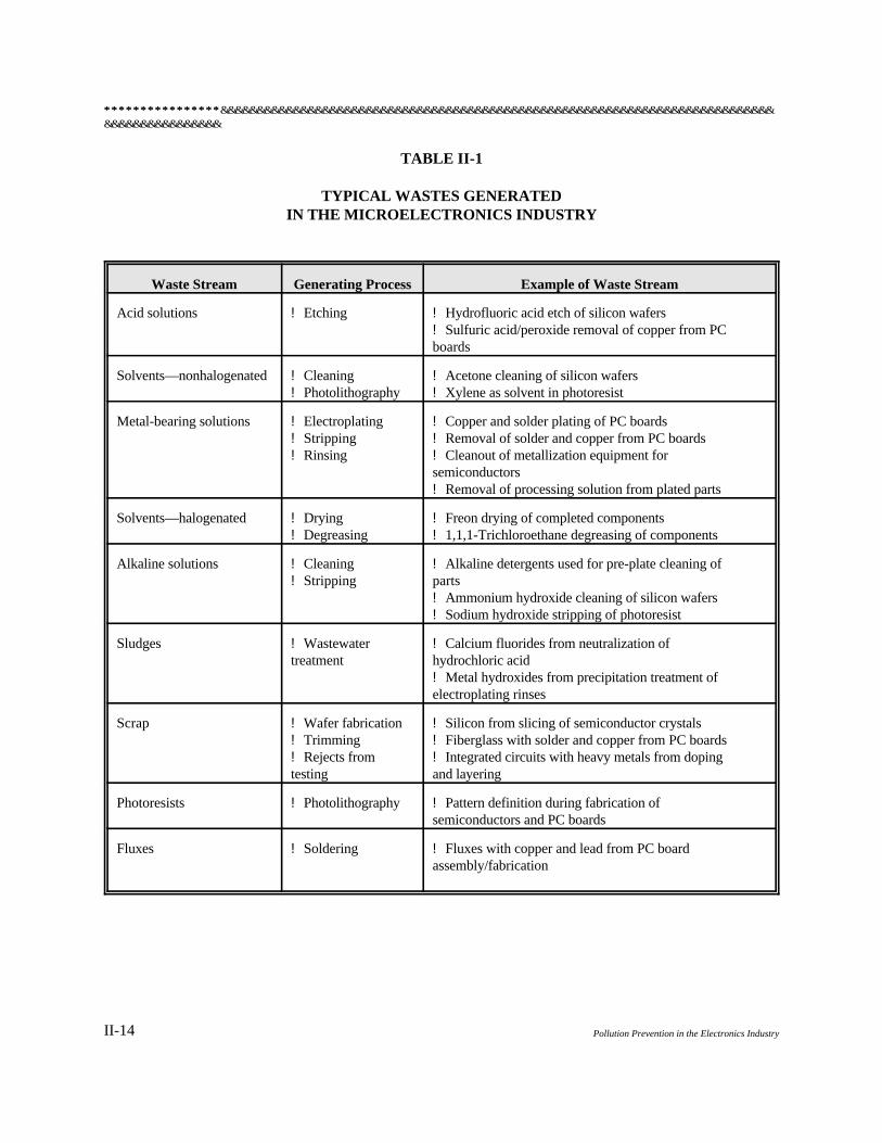
The PC board and semiconductor industries generate numerous waste streams (Table II-1), includingwastewater, spent process solutions, waste solvents, wastewater treatment sludges, solids, and airemissions. The following paragraphs discuss the major waste streams generated by the PC board andsemiconductor industries, and the practices typically used to manage these wastes.
Wastes from PC board and semiconductor facilities can be managed onsite or offsite, depending on (1)the characteristics of the waste, (2) the resources of the facility, (3) the availability and cost of off-sitetreatment and disposal facilities, and (4) regulatory requirements. These industries typically treat rinsewaters onsite and then discharge to the sewer, and dispose of concentrated wastes—such as wastewatertreatment sludges, process baths, and waste solvents—offsite.
In the electronics industry, components are generally cleaned after soldering to remove contaminants,which originate from the fluxes used to promote the wetting necessary for the formation of good solderjoints. The flux residue can interfere with future processes and reduce the aesthetics and reliability ofa component. Traditionally, chlorinated, fluorinated, and other halogenated solvents have been used toremove these residues. Halogenated solvents are used because of their stability, ease of drying, andeffectiveness in removing oils. These same characteristics, which make these solvents effective incleaning processes, have detrimental effects on the environment. Solvent evaporation has beeninvestigated for its role in stratospheric ozone

&&&&&&&&&&&&&&&&&&&&&&&&&&&&&&&&&&&&&&&&&&&&&&&&&&&&&&&&&&&&&&&&&&&&&&&&&&&&&&&&&&&&&&&&&&&&********************************
II-13THE MICROELECTRONICS INDUSTRY
********************************&&&&&&&&&&&&&&&&&&&&&&&&&&&&&&&&&&&&&&&&&&&&&&&&&&&&&&&&&&&&&&&&&&&&&&&&&&&&&&&&&&&&&&&&&&&&
II-14 Pollution Prevention in the Electronics Industry
TABLE II-1
TYPICAL WASTES GENERATEDIN THE MICROELECTRONICS INDUSTRY
Waste Stream Generating Process Example of Waste Stream
Acid solutions ! Etching ! Hydrofluoric acid etch of silicon wafers! Sulfuric acid/peroxide removal of copper from PC boards
Solvents—nonhalogenated ! Cleaning ! Acetone cleaning of silicon wafers! Photolithography ! Xylene as solvent in photoresist
Metal-bearing solutions ! Electroplating ! Copper and solder plating of PC boards! Stripping ! Removal of solder and copper from PC boards! Rinsing ! Cleanout of metallization equipment for
semiconductors! Removal of processing solution from plated parts
Solvents—halogenated ! Drying ! Freon drying of completed components! Degreasing ! 1,1,1-Trichloroethane degreasing of components
Alkaline solutions ! Cleaning ! Alkaline detergents used for pre-plate cleaning of ! Stripping parts
! Ammonium hydroxide cleaning of silicon wafers! Sodium hydroxide stripping of photoresist
Sludges ! Wastewater ! Calcium fluorides from neutralization of treatment hydrochloric acid
! Metal hydroxides from precipitation treatment of electroplating rinses
Scrap ! Wafer fabrication ! Silicon from slicing of semiconductor crystals! Trimming ! Fiberglass with solder and copper from PC boards! Rejects from ! Integrated circuits with heavy metals from doping testing and layering
Photoresists ! Photolithography ! Pattern definition during fabrication of semiconductors and PC boards
Fluxes ! Soldering ! Fluxes with copper and lead from PC board assembly/fabrication
&&&&&&&&&&&&&&&&&&&&&&&&&&&&&&&&&&&&&&&&&&&&&&&&&&&&&&&&&&&&&&&&&&&&&&&&&&&&&&&&&&&&&&&&&&&&********************************
II-15THE MICROELECTRONICS INDUSTRY
depletion, global warming potential, and formation of smog. Using halogenated solvents not onlygenerates hazardous solvent wastes, but it also creates work conditions that may be detrimental to thehealth and safety of workers. Because environmental regulations restrict the use of such solvents, manyindustries are attempting to reduce or eliminate their use of halogenated solvents. Additional restrictionsare expected.
Wastewaters are generated from numerous processes—including cleaning, etching, stripping, cooling,finishing, and exhaust scrubbing—and often constitute the largest volume of waste generated by PCboard and semiconductor operations. The rinse waters typically have a low pH resulting from acidcleaning operations, and may contain numerous pollutants, including suspended solids, metals, fluoride,phosphorus, and chelating agents. Typical waste management practices include a combination of wastestream segregation, in-line treatment, end-of-pipe treatment, and off-site disposal and treatment. Metalsare usually removed from the wastewater with a combination of pH adjustment, coagulation,flocculation, precipitation, and filtration, which produces a sludge that is disposed of offsite. Cyanide-bearing waste streams are segregated for cyanide destruction before treatment, or are transported offsitefor treatment and disposal.
Spent hydrofluoric acid is the principal waste acid solution; others include sulfuric, nitric, fluoboric,hydrochloric, and acetic acid solutions. Spent acid solutions may be segregated for off-site disposal ordischarged to the facility's wastewater treatment system for neutralization and sewer discharge. Theprincipal components of the facility effluent include fluoride, toxic organics, heavy metals, and, in someinstances, suspended solids. Wastewaters may contain several heavy metals resulting from electroplatingoperations, including chromium, copper, lead, nickel, and zinc. In addition, significant concentrationsof arsenic are found in rinse waters of facilities that use gallium arsenide and indium arsenide as rawmaterial for crystals. The waste streams from layering (metallization) include spent solutions of preciousmetals, heavy metals, and acids, and a large volume of dilute acid/water wastewater.
Spent chlorinated organic solvents may be gravity-separated and recovered in-house, or transportedoffsite for reclamation, or treatment and disposal. The major wastes in fluxing and soldering are thesolder wastes, which contain lead and solvents needed to clean the boards after soldering. Spent platingbaths result from the electroless copper deposition process and electroplating with copper, tin/leadsolder, and precious metals. These waste streams constitute a significant volume of waste generated byPC board operations. Spent electroless copper is not amenable to treatment by traditional metalflocculation, coagulation, and precipitation methods, because the copper is in a complex chelated form.Therefore, spent electroless copper baths are usually drummed and hauled away for treatment anddisposal. Spent resist stripper solution contains dilute caustic soda (sodium hydroxide) and chemicalcomponents of the resist, including epoxy polymers, chlorinated aromatic organics, methacrylates, andother organic compounds. The spent resist stripper solution typically is drummed and hauled offsite fortreatment and disposal. Fluoride originates from hydrofluoric acid, which is used as an etchant andcleaner. The major source consists of spent hydrofluoric acid solutions; the minor source is waste rinsewater.
Airborne particulate matter is generated by cutting, sanding, drilling, and slotting operations duringboard preparations. The particulates are typically collected by using air pollution control devices, or aremanually swept up, and are disposed of, with other solid wastes, at landfills. Wet air scrubbers may be

********************************&&&&&&&&&&&&&&&&&&&&&&&&&&&&&&&&&&&&&&&&&&&&&&&&&&&&&&&&&&&&&&&&&&&&&&&&&&&&&&&&&&&&&&&&&&&&
II-16 Pollution Prevention in the Electronics Industry
used to remove acid, alkaline, and solvent fumes in exhaust from cleaning, etching, and degreasingoperations. The scrubbed air passes to the atmosphere, and the scrubber liquid is neutralized with otheracidic waste streams. Organic fumes from degreasing operations may be treated by passing the airstream over a bed of activated carbon, which adsorbs the organic vapors. In many instances, however,airborne emissions are discharged to the atmosphere without treatment.
Suspended solids may arise in waste streams from wafer slicing, grinding, and lapping operations. Thiswaste stream may be hauled off for disposal or discharged to the facility's wastewater treatment systemfor treatment, if necessary.
Waste from the oxidation step includes silicon dioxide or other raw material, hydrofluoric acid, and waferrinse water.
The doping process produces solid wastes containing arsenic, antimony, phosphorus, arsine, diborane,and waste pump oils.
The photolithography process (photoimaging) produces a substantial portion of the wastes in thesemiconductor industry. The major waste streams are waste developer (xylene and other nonhalogenatedsolvents or caustic) and waste photoresist (orthodiazo-ketone or isoprene rubber). Spent processsolutions from photolithography operations—such as resist, resist stripper, and developer—may containmixtures of caustics, chlorinated aromatic organics, polymers, and other organic compounds. Thesewastes are usually containerized and hauled off for treatment and disposal.
POLLUTION PREVENTION OPTIONS FOR THE MICROELECTRONICSINDUSTRY
Source Reduction through Material Changes
DEIONIZED WATER
Because the electronics industry requires high-purity process chemicals, it is likely that purified waterwould be in widespread use. This is certainly the case in segments of the semiconductor industry.However, large numbers of other electronics facilities still use tap water—which contains highconcentrations of dissolved ions—in process solutions and rinsing systems. When treated byconventional precipitation methods, this water can yield sludge that contains as much as 90 percent, byvolume, precipitated hard-water ions. Using high purity or deionized water (instead of tap water) forcleaning not only reduces the volume of sludge generated, but also enhances the performance ofrecovery technologies, such as ion exchange and rinse water reuse.
FLUXING AND SOLDERING
&&&&&&&&&&&&&&&&&&&&&&&&&&&&&&&&&&&&&&&&&&&&&&&&&&&&&&&&&&&&&&&&&&&&&&&&&&&&&&&&&&&&&&&&&&&&********************************
II-17THE MICROELECTRONICS INDUSTRY
Traditionally, environmentally harmful CFC compounds were used in the electronics industry to cleanthe residue left behind by conventional fluxes. Excess flux must be removed from each board.Therefore, if excess flux can be minimized or eliminated, the chemicals used to remove the excess fluxcan also be minimized or eliminated. Several alternative fluxes (often referred to as "no-clean fluxes")are designed to leave a minimal residue that does not require an additional process step for cleaning.
Alternative Fluxes
Two types of alternative fluxes are water-soluble and low-solids fluxes. These fluxes require cleaningafter soldering; however, they can be cleaned with alcohol or aqueous-based cleaners that are moreenvironmentally benign than traditional solvents. One example of this type of flux is a nontoxic,nonflammable, citric acid-based flux developed by Sandia National Laboratory.
Using low-solids fluxes (LSF) before soldering results in little or no visible residue on PC boards.Therefore, cleaning with solvents is not needed. LSFs contain only 1 to 10 percent nonvolatilematerials by weight, compared to 15 to 35 percent found in conventional fluxes. LSFs are noncorrosiveand have high insulation resistance, thereby preventing the need for removal of trace residues in mostcases. However, even trace residues may affect reliability of certain products. Other processes thatimprove the reliability of the component include the LSF applicator and inert atmosphere ovens. AT&Tdeveloped the LSF applicator to apply less flux via a spray fixture that can be adjusted very preciselyto achieve controlled uniform flux coverage. Because the small quantity of organic solids in LSFs isvolatile, reoxidation of exposed surfaces during reflow is a major cause of poor soldering. Eliminatingoxygen by creating an inert atmosphere (nitrogen) improves solder reliability with LSFs. Alteration ofequipment may be necessary to use LSFs, especially if an inert atmosphere is needed for best results.The purchase and application costs of LSFs are comparable to those for conventional fluxes.Elimination of the cleaning step results in economic benefits. The LSF applicator would beapplicable to through-hole component circuit boards only, where fluxes are needed to promote wettabilityso that solder joints can be formed.
Benefits are as follows:
! Conversion to this technology is easy.
! LSFs eliminate the need for defluxing and for the use of solvents.
! Capital costs are low.
Limitations are as follows:
! Special equipment, such as an LSF applicator, may be required.
! Limited residues are unacceptable in many military specifications.
! Activity of LSFs is limited to a short dwell time.
********************************&&&&&&&&&&&&&&&&&&&&&&&&&&&&&&&&&&&&&&&&&&&&&&&&&&&&&&&&&&&&&&&&&&&&&&&&&&&&&&&&&&&&&&&&&&&&
II-18 Pollution Prevention in the Electronics Industry
! Cleanliness requirements may be stricter for components and PC boards.
The AT&T plant in Columbus, Ohio, converted completely to an LSF system. The plant eliminatedpost-solder cleaning and the use of 30,000 gallons of perchloroethylene (PCE) annually. Using the fluxapplicator also reduced the amount of flux material product used by about 2,000 gallons per year. Costsavings at the plant are estimated at $145,000 per year as a result of the decreased need to purchase,treat, track, and report on this solvent.
Protective Coatings
Protective coatings can reduce the need for a flux, which can reduce the need for cleaning.Nonoxidizing surfaces, such as gold or other alloys, can be wetted by solder without fluxing. However,the thickness of a gold layer must be carefully controlled when using tin-based solder alloys, becausegold and tin react to form a brittle intermetallic that could weaken a solder joint if excess gold is applied.
Conversely, a thin, porous layer of gold might expose the underlying metal to oxidation or corrosion ina poorly controlled storage environment. For this scenario, organic inhibitors are being developed thatcould be applied to the protective coatings to guard against oxidation. The combination of protectivecoatings and organic inhibitors may allow for fluxless soldering.
Alternative Solder Materials
Because the presence of lead in solder is an environmental concern, various lead-free solders have beeninvestigated. One promising alternative is bismuth, a by-product of lead and copper refining. Anotherinnovative approach is to replace metallurgical solders with a conductive adhesive. For solderreplacement, silver-filled epoxies are typically used. A company must consider all process variablesbefore replacing solders. However, replacing lead solders could eliminate the need for cleaning atthis step, which could provide a considerable cost savings.
CLEANING
Aqueous Cleaners
Aqueous cleaners are mixtures of water, detergents, and other additives that promote the removal oforganic and inorganic contaminants from hard surfaces, rather than dissolving them in an organicsolvent. Each component performs a distinct function and affects the way in which the contaminant isremoved from the substrate.
Surfactants provide detergency by lowering the surface and interfacial tensions of the water so that thecleaner can better penetrate small spaces and lift contaminants from the substrate. Deflocculants helpto maintain the dispersion of contaminant particles in the cleaning medium. Because many emulsionsremain stable only at elevated temperatures and under alkaline conditions, separation of the oily fractionfrom the aqueous cleaner can often be induced by lowering temperature and acidifying the bath.Saponifiers react chemically with oils containing fatty acids (vegetable oils and animal fats) to formsoaps. Coupled with saponifiers, surfactants can act as wetting agents to help to remove contaminants
&&&&&&&&&&&&&&&&&&&&&&&&&&&&&&&&&&&&&&&&&&&&&&&&&&&&&&&&&&&&&&&&&&&&&&&&&&&&&&&&&&&&&&&&&&&&********************************
II-19THE MICROELECTRONICS INDUSTRY
from the surface. Organic amines can react with many common hydrocarbon contaminants, includingthe saponifiable portion of solder flux rosin; however, organic amines are hazardous. Sequesteringagents prevent the mineral content of hard water from forming insoluble products with the cleaner. Theiruse enables the cleaner to attack only the contaminant and ensures that lower cleaner concentrations areneeded.
In aqueous cleaning, alkalis, deflocculants, and sequestering agents are referred to as builders. Anti-foaming agents and corrosion inhibitors may be added to enhance the performance of builders.Corrosion inhibitors either passivate the surface by adsorbing onto it a molecular species that will (1)react with oxygen before the metal can oxidize, or (2) form a protective barrier over the surface thatexcludes oxygen. Drying methods include accelerated evaporation (hot air recirculation, evaporativedrying), displacement (capillary or slow-pull drying), and mechanical removal (air knives, centrifugaldrying). Primary detergents are used to process buffed metals at temperatures of at least 120 F.o
Alkaline detergent cleaners are used to remove light oils and residues (including solvents or other typesof cleaners) at elevated temperatures ranging from 120 F to 200 F.o o
Figure II-3 is a schematic diagram of an aqueous cleaning process.
Benefits of aqueous cleaners are as follows:
! Effectively remove inorganic/ionic contaminants, particulates, and films.
! Flexible in application and available cleaning methods.
! Performance can easily be enhanced by formulation, dilution, and temperature.
! Effectively remove most oils and greases.
! Contain few hazardous chemicals.
! Water can be recycled.
! Generally pose less risk to personnel and the environment.
Limitations of aqueous cleaners are as follows:
! Compatibility with some materials is limited, possibly leading to metal corrosion orstress corrosion cracking.
! Use may require drying of parts or components.

********************************&&&&&&&&&&&&&&&&&&&&&&&&&&&&&&&&&&&&&&&&&&&&&&&&&&&&&&&&&&&&&&&&&&&&&&&&&&&&&&&&&&&&&&&&&&&&
II-20 Pollution Prevention in the Electronics Industry

&&&&&&&&&&&&&&&&&&&&&&&&&&&&&&&&&&&&&&&&&&&&&&&&&&&&&&&&&&&&&&&&&&&&&&&&&&&&&&&&&&&&&&&&&&&&********************************
II-21THE MICROELECTRONICS INDUSTRY
! Wastewater treatment is necessary to mitigate human and environmental risksfollowing disposal.
Semiaqueous Cleaners
Semiaqueous cleaners comprise a group of cleaning solutions that are composed of natural or syntheticorganic solvents, surfactants, corrosion inhibitors, and other additives. The term "semiaqueous" refersto the use of water in some parts of the cleaning process, such as washing and rinsing. Semiaqueouscleaners are designed to be used in process equipment designed for aqueous cleaners. Commonly usedsemiaqueous cleaners include water-immiscible types (terpenes, high-molecular-weight esters, petroleumhydrocarbons, and glycol ethers) and water-miscible types (low-molecular-weight alcohols, ketones,esters, and organic amines).
Figure II-4 is a schematic diagram of a semiaqueous cleaning process. Figure II-5 is a schematic diagramof a typical piece of spray equipment used to apply semiaqueous cleaners. Terpenes are naturalhydrocarbons derived from plant sources such as citrus and pine oils. Types of terpenes include d-limonene, a- and b-pinene, and para-menthadienes. In water, terpenes form emulsions if they arestabilized by surfactants and other additives. In cleaning applications, terpenes may be diluted for useon less difficult contaminants. Dilution reduces cleaning performance but decreases usage, reducesexpense, and lowers vapor pressure, thereby decreasing vapor emissions.
Esters have good solvent properties and are soluble in most organic compounds. High-molecular-weightesters have limited solubility in water, but may be used—either cold or heated—to improve cleaningperformance. Types of high-molecular-weight esters that are most commonly used in cleaning includealiphatic mono-esters and dibasic acid esters. Among the low-molecular-weight esters, which are water-soluble, ethyl lactate is reported to have good cleaning, health, and safety properties. Ethyl lactate is aVOC, with a moderate flash point of 126 F. o
Glycol ethers have good solvent properties and are soluble in most organic compounds, but they posea health risk. They form emulsions with water that can be separated for recycling. N-methyl-2-pyrrolidone (NMP) is completely miscible with water and organic compounds, and can be used—coldor heated—because of its high flash point (about 199 F). Also, NMP is effective for cleaning at diluteo
concentrations.
Semiaqueous cleaners are designed to be water-rinsable and nonwater-rinsable. After being washed ina water-rinsable cleaner, cleaned parts may be rinsed in water to remove residue. Parts cleaned with anonwater-rinsable cleaner are rinsed in a secondary tank with alcohol or other organic solvent to capturedrag-out cleaner, which is residual cleaner carried over from the previous tank. Several technologiesenable separation of semiaqueous cleaners from the wastewater to be recycled or discharged fortreatment.

********************************&&&&&&&&&&&&&&&&&&&&&&&&&&&&&&&&&&&&&&&&&&&&&&&&&&&&&&&&&&&&&&&&&&&&&&&&&&&&&&&&&&&&&&&&&&&&
II-22 Pollution Prevention in the Electronics Industry

&&&&&&&&&&&&&&&&&&&&&&&&&&&&&&&&&&&&&&&&&&&&&&&&&&&&&&&&&&&&&&&&&&&&&&&&&&&&&&&&&&&&&&&&&&&&********************************
II-23THE MICROELECTRONICS INDUSTRY
********************************&&&&&&&&&&&&&&&&&&&&&&&&&&&&&&&&&&&&&&&&&&&&&&&&&&&&&&&&&&&&&&&&&&&&&&&&&&&&&&&&&&&&&&&&&&&&
II-24 Pollution Prevention in the Electronics Industry
Proper use of these cleaners is required to reap their full pollution prevention benefits. Goodengineering design is essential so that air emissions can be kept low. Examples of good engineeringdesign are as follows:
! Operation of the cleaning bath at the minimum temperature at which acceptablecleaning performance is obtained
! Use of low-vapor-pressure cleaning agents
! Minimization of dragout by using air knives
! Maintenance of the air exhaust rate at a minimum level
In general, semiaqueous cleaners have excellent solvency for numerous difficult contaminants,such as heavy grease, tar, and waxes. The cleaners have low surface tension, which decreases theircontact angles and enables them to penetrate small spaces, such as crevices, blind holes, and below-surface-mounted electronic components. As with aqueous cleaners, rinsing is necessary to avoidleaving a residue on the cleaned parts. If they are rinsed with water, the parts must be dried. If a volatileorganic solvent, such as alcohol, is used to rinse the parts, drying will be accelerated. Semiaqueouscleaners are widely available. Drum-sized quantities are typically priced from $10 to $20 per gallon forterpenes, esters, and glycols, and from $25 to $30 per gallon for NMP.
Advantages of semiaqueous cleaners over aqueous cleaners include the following:
! More aggressive in removing heavy organic contaminants
! Lower corrosion potential with water-sensitive metals and most plastics
! Easier penetration of small spaces, because of lower surface tensions
! Biodegradability, which facilitates direct discharge of diluted semiaqueous cleaners tothe sewer system
Limitations include health concerns and low flash points. Mists of concentrated semiaqueous cleanerscan be ignited at room temperature, which can restrict safe operating temperatures in some cases.Washing equipment should be designed to avoid creating mists, such as by spraying or agitating belowthe fluid surface or by using ultrasonic action. Potential concerns associated with the improper oruncontrolled handling of semiaqueous cleaners include health-related problems, strong odors, andtoxicity.
The primary pollution prevention benefit of semiaqueous cleaners is that they do not deplete thestratospheric ozone layer. These cleaners are also biodegradable but may require add-on treatment inolder industrial wastewater treatment systems. A batch-type or continuous-flow fixed-film biologicalreactor is recommended to process rinse water from semiaqueous cleaning to increase residence time andeffect complete degradation.
&&&&&&&&&&&&&&&&&&&&&&&&&&&&&&&&&&&&&&&&&&&&&&&&&&&&&&&&&&&&&&&&&&&&&&&&&&&&&&&&&&&&&&&&&&&&********************************
II-25THE MICROELECTRONICS INDUSTRY
ETCHING AND PHOTORESIST
Dry Film Resist
Early types of photoresist used to create patterns on PC boards required the use of chlorinated solventsto first develop, and then strip, the coating. A newer process, termed "dry film resist," is mechanicallylaminated to the PC board, and the image is transferred by exposure to UV light through a maskoutlining the patterns of the circuitry. This type of resist can then be stripped in various semiaqueoussolutions, which can be discharged to the municipal wastewater treatment plant with minimal filtrationand monitoring. Changing to this type of resist will enable a company to significantly reduce theuse of chlorinated solvents and still produce PC boards that are more sophisticated. However,operating costs are currently higher than those for the traditional silkscreening process.
Alkaline Permanganate Desmear and Etchback
After holes are drilled in a PC board, two other operations may be needed. One is desmearing, whichis the removal of friction-melted epoxy resin and drilling debris from the holes. The other is etchback,which is the removal of epoxy polymer, especially between the layers of a multilayer board. Commonmaterials used for these processes include chromic acid and concentrated sulfuric acid, which have highprocess costs because of waste treatment requirements. An alternative solution for both desmearing andetchback, based on the reduction of permanganate, has the advantage of operating in a closed loop byusing regeneration. An oxidizer is added as needed to restore the permanganate concentration;occasionally, the solution can be chilled to recover the waste, which consists of crystals of manganeseoxide. Processing experience shows excellent solution life and performance, but it is usable only withspecific types of board materials, such as epoxy and polyimide.
Source Reduction through Process Changes
FLUXING AND SOLDERING
Fluxless and No-Clean Soldering
An inert soldering atmosphere can eliminate the need for flux and, consequently, for cleaning (no-clean soldering). Without the cleaning process, solvents are not needed. Because reoxidation ofexposed surfaces during reflow is a major cause of poor soldering, one solution is to eliminate oxygen.Because of its availability and low cost, nitrogen is often used.
Benefits of no-clean soldering are as follows:
! Eliminating flux eliminates the need for cleaning.
! Eliminating use of both flux and cleaning results in a simpler process, thereby resultingin economic and process time savings.
! Eliminating flux also eliminates any flux residue, which may cause reliability problems.
********************************&&&&&&&&&&&&&&&&&&&&&&&&&&&&&&&&&&&&&&&&&&&&&&&&&&&&&&&&&&&&&&&&&&&&&&&&&&&&&&&&&&&&&&&&&&&&
II-26 Pollution Prevention in the Electronics Industry
! Solder loss may be reduced.
Limitations of no-clean soldering are as follows:
! Tighter control and higher precision are required in the reflow process.
! Slightly higher skill level is required for operation.
! It requires an initial capital outlay for a new furnace.
No-clean fluxes can be applied without special methods, resulting in significantly reduced flux residues;however, even small amounts of residue may affect product performance. No-clean fluxes are often usedin combination with various clean or reducing atmospheres to maintain or produce a solderable basesurface. Inert or reducing gases, reactive plasmas, and activated acid vapors have been used to createatmospheres that restrict the supply of oxygen to the workpiece during heating and soldering operations.When controlled atmospheres are used with LSFs, the flux residues are usually negligible.
One fluxless soldering process uses nitrogen-controlled reflow soldering machines with activators thatare applied on the surface of the board. The activators are various acids (often formic or abietic acid).Because the oxygen content of the process is controlled, no oxides form on the boards, and the residuesdo not need to be cleaned up. This process should be thoroughly researched before it is incorporated intoa production process, but it is a single-step process that eliminates the need for liquid cleaning systems.
CLEANING
Automated Aqueous Cleaning
Automated aqueous cleaners use aqueous cleaning solutions, instead of solvents, to achieve high-qualitycleaning. This technology generates a waste stream that is less hazardous and reduces the amountof wastewater generated. The process removes some of the contamination that comes off of thecomponents being cleaned into the cleaning solution. The cleaning solution can then be recirculatedseveral times.
The automated aqueous washer sprays an aqueous solution across the components to remove residuesor debris (Figure II-6). The components move through a series of chambers, each having a differentconcentration of cleaning and rinsing solution. Excess sprayed solution is recovered and reused. Atypical unit consists of a series of five compartments through which the soiled metal

&&&&&&&&&&&&&&&&&&&&&&&&&&&&&&&&&&&&&&&&&&&&&&&&&&&&&&&&&&&&&&&&&&&&&&&&&&&&&&&&&&&&&&&&&&&&********************************
II-27THE MICROELECTRONICS INDUSTRY
********************************&&&&&&&&&&&&&&&&&&&&&&&&&&&&&&&&&&&&&&&&&&&&&&&&&&&&&&&&&&&&&&&&&&&&&&&&&&&&&&&&&&&&&&&&&&&&
II-28 Pollution Prevention in the Electronics Industry
parts are transported via a helical screw conveyor. The parts are sprayed successively with solutionsfrom five holding tanks, one per compartment. The first compartment sprays hot water on the parts,which helps to break the residual machining fluids (oil-water emulsions). The second and thirdcompartments spray two different concentrations of detergent solutions on the parts, followed by a cleanwater rinse in the fourth compartment. The fifth and final compartment sprays a rust inhibitor solution,if required. A dryer vaporizes any water droplets remaining on the parts. Used solutions are recirculatedfor a period of relatively continuous operation in a closed-loop system. Separator tanks separate oil anddebris from the used solutions. Because recovery and reuse of the cleaning solution is automatic, the unitrequires very little operator attention. The main features of this type of washer are (1) improved contactbetween the part surface and the cleaning solution, and (2) several recovery and reuse cycles of cleaningsolution. Some new units claim zero wastewater discharge, with fresh water added only to compensatefor evaporation in the dryer.
Benefits of automated aqueous cleaning are as follows:
! Improved contact between cleaning solution and parts being cleaned enables cleaningof most types of parts without solvents.
! Solvent use can be reduced or eliminated.
! Cleaning effectiveness is comparable to that of vapor degreasing or conventionalaqueous cleaning processes.
! Amount of wastewater generated is lower than that generated by traditional processes.
! Installation and operation are easy; labor and skill requirements are low.
! Technology consumes less cleaning chemicals than traditional processes.
! Continuous operation enhances plant efficiency.
! Operating cost savings are realized.
Limitations of automated aqueous cleaning are as follows:
! Wastewater generated must be treated and discharged.
! Some types of parts cannot be cleaned as effectively.
! Because of drying, energy requirement is high.
! Initial capital cost is relatively high.
! Drying can leave spots if rinsing is inadequate or rinse water contains a high level of
&&&&&&&&&&&&&&&&&&&&&&&&&&&&&&&&&&&&&&&&&&&&&&&&&&&&&&&&&&&&&&&&&&&&&&&&&&&&&&&&&&&&&&&&&&&&********************************
II-29THE MICROELECTRONICS INDUSTRY
dissolved solids.
Laser Cleaning
Laser cleaning involves the use of short pulses of high-peak-power radiation to rapidly heat and vaporizethin layers of material surfaces. The vapors are removed by being entrained into a flowing gas streambefore they can recondense and recontaminate the material surface. On a nonmetallic surface, such asthat of a semiconductor, the primary contaminants are oxide films and absorbed metal ions. Over thepast 25 years, ruby, alezandrite, and carbon dioxide (CO ) lasers have been used for cleaning; however,2
more recently, excimer lasers have been used for laser cleaning of semiconductor substrates.
Laser ablation is the mechanism involved during laser cleaning of semiconductor substrates. Laserablation vaporizes thin layers of contaminants at the air-contaminant interface. Efficient use requiresthat the contaminant be strongly absorbing at the laser wavelength. Consequently, UV lasers, such askrypton-fluoride (KrF) excimers, have been used most for this cleaning application. UV wavelengthscan clean more efficiently than other laser wavelengths because the absorption depth into oxides is muchsmaller (about 10 nanometers [nm]) in the UV region.
Liquid-assisted laser cleaning is a variation in the use of lasers for cleaning. In microfabrication ofsemiconductor devices, residual micron-size particles cause defects on the same scale as that of themicrostructure being produced in the process. These micron-size particles are extremely difficult toremove, because the binding forces (Van der Waals, capillary, and electrostatic) that hold them on thesurface are much greater than the gravitational and inertial forces at this particle size. Benign-liquid-assisted laser-cleaning techniques successfully achieve particulate removal without the use of FreonTM
(CFC-113) or harsh solvents.
One technique, developed at IBM, involves forming a very thin volatile liquid layer (water, ethanol,methanol, isopropanol, and mixtures thereof) on the surface to be cleaned immediately before deliveryof a short laser pulse. The liquid works its way under the particles by capillary action and is explosivelyevaporated by conduction of heat from the substrate, which is heated directly by the laser pulse. At IBM,the process was conducted on silicon surfaces exposed to 16-nanosecond laser pulses from a KrFexcimer laser (0.248 micrometer wavelength). The process is a dry-cleaning process because of the shortresidence time of the liquid on the surface. In a slightly different approach, micron- and submicron-sizedparticles were cleaned from silicon substrates by using a laser wavelength that is absorbed directly withthe liquid deposited as the assist layer rather than in the substrate itself. Water was found to be the bestliquid, and the CO TEA laser (100-nanosecond pulse, 1 microsecond tail) with 9.6- and 10.6-2
micrometer wavelength was used.
Benefits of laser cleaning include the following:
! Area to be cleaned can be highly selective and sharply defined.
! Process is generally very fast and energy efficient.
! No foreign atoms are introduced to the surface as they are in ion bombardment
********************************&&&&&&&&&&&&&&&&&&&&&&&&&&&&&&&&&&&&&&&&&&&&&&&&&&&&&&&&&&&&&&&&&&&&&&&&&&&&&&&&&&&&&&&&&&&&
II-30 Pollution Prevention in the Electronics Industry
techniques.
! If cleaning is performed in a vacuum, the vacuum is not compromised, because the lasersource can be located outside of the cleaning chamber.
! Thermal diffusion of bulk impurities to the surface is avoided because of the extremelylarge quenching rate afforded by the very short pulses that are available.
! The removal rate can be easily controlled by changing the beam fluence or pulserepetition rate.
! Laser cleaning is amenable to "dry" effluent control through cover gas filtering.
! Liquid-assisted laser cleaning removes micron-sized particles.
Limitations of laser cleaning include the following:
! Laser cleaning requires a special cleaning chamber.
! Laser energy may damage some substrates.
Plasma Cleaning
Plasma cleaning is one type of surface processing, among several, that depends on production of a low-pressure steady-state plasma in a special vacuum chamber. These processes include ion plating, plasma-enhanced chemical vapor deposition, etching, cleaning, and surface modification. Plasma cleaning hasa relatively low cleaning rate that is best used to remove thin contaminant films.
In typical plasma processing, the excitation of the gas may be from a direct current (DC), radiofrequency(RF), or microwave power source. If an inert gas is used, the ions and neutrals in the plasma bombardthe surface to be cleaned and sputter off the contaminant in a purely physical manner, molecule bymolecule. If a reactive gas is used in the plasma, the bombarding ions may also react with thecontaminants and form gaseous species that evaporate from the surface.
Recent research indicates that plasma cleaning has value in cleaning PC boards. IBM researchersfound that RF reactive cleaning with oxygen-carbon tetrafluoride may be used to remove epoxy/glassparticle/copper drill smears in drilled through-holes in PC boards.
One benefit of plasma cleaning is that it can accomplish ultrafine cleaning. However, this type ofcleaning (1) requires a special cleaning chamber and (2) is a relatively slow process.
Carbon Dioxide Snow
Gaseous or liquid CO is drawn from a room-temperature gas cylinder or high-pressure dewar and2
&&&&&&&&&&&&&&&&&&&&&&&&&&&&&&&&&&&&&&&&&&&&&&&&&&&&&&&&&&&&&&&&&&&&&&&&&&&&&&&&&&&&&&&&&&&&********************************
II-31THE MICROELECTRONICS INDUSTRY
expanded through a nozzle to produce fine CO particles and CO gas. These particles, which are dry2 2
ice "snowflakes," are propelled by the gas stream. When the gas or liquid is throttled through a specialnozzle and expanded to form a jet, it undergoes a phase change into the solid state. The shape and sizeof the snowflakes depend on the configuration of the nozzle and the conditions in which the flake formedin the gas stream. The snowflakes can be individual crystals or collective groupings of crystallites.
Cleaning is performed when the snow particles affect a contaminated surface, dislodge adherentcontaminant particles, and carry them away in the gas stream. The process is effective in removingvery small (submicron) particles, in which fluid drag typically restricts the performance of liquidphase cleaning. The CO snow cleaning process is also believed to attach hydrocarbon film by2
dissolving hydrocarbon molecules in a temporal liquid CO phase at the film-substrate interface. The2
dissolved film is then carried away by the subsequent flow of snow and gas.
CO snow gently removes particles, ranging from smaller than 10 microns in diameter to 0.1 micron, that2
are difficult to remove by using high-velocity liquid nitrogen. It is used to remove light oils andfingerprints from mirrors, lenses, and other delicate surfaces, and from precision assemblies, withoutscratching the surface. CO snow can clean hybrid circuitry and integrated circuits without2
disturbing the bonding wires. No other cleaning mechanism can duplicate this unique ability. Inthe disk drive industry, CO snow is used to remove particles from disks without damage to the2
operation. If the dust or dirt particles removed by the snow are a hazard, they can be collected by anelectrically charged curtain.
The process is used to remove paste fluxes in soldering. If the grease cannot be removed with the snow,a combination of CO snow and ethyl alcohol is effective, followed by CO snow alone to remove the2 2
impurities from the alcohol.
CO is used to remove hydrocarbons and silicone grease strains from silicon wafers. Wafers that were2
artificially contaminated with a fingerprint, a nose print, and a thin silicone grease film were found tohave surface hydrocarbon levels that were 25 to 30 percent lower after CO snow cleaning than those2
of the original wafer surfaces. Reportedly, high-velocity CO snow reduced zinc orthosilicates and other2
particles—ranging from 0.1 to 0.5 micron in diameter—on a silicon wafer by more than 99.9 percent.
A complete system includes a CO purifier, a pneumatic-actuated head, and a microprocessor-based2
timing circuit. Several models of manual spray booths are available that provide a nitrogen-purged,heated, and monitored environment for CO spraying costing from $10,000 to $15,000. 2
CO snow has the following benefits:2
! It performs ultrapure cleaning of light oils down to submicron size on the most delicateand sensitive materials, ranging from bonding wires to precision mirrors in telescopes.
! It adjusts to a wide range of size and intensity.
! It does not create thermal shock, is nonflammable and nontoxic, and causes noundesirable chemical reactions.
********************************&&&&&&&&&&&&&&&&&&&&&&&&&&&&&&&&&&&&&&&&&&&&&&&&&&&&&&&&&&&&&&&&&&&&&&&&&&&&&&&&&&&&&&&&&&&&
II-32 Pollution Prevention in the Electronics Industry
! It is noncorrosive and leaves no residue.
! No media separation system is required; there is no media disposal cost.
! It penetrates nonturbulent areas to dislodge contaminants without disassembly.
CO snow has the following limitations:2
! Heavier oils may require chemical precleaning and/or heating.
! CO must be purified, resulting in an added expense, because of its tendency to dissolve2
contaminants from the walls of tanks in which it is stored.
! Because of long dwell times, airborne impurities may condense on excessively chilledsurfaces.
! Although CO snow will not scratch most metals and glasses, hard particulates on a2
surface may cause scratching when they become airborne (carried by the gas stream).
Catalytic Wet Oxidation Cleaning
Catalytic wet oxidation is a proposed method for chemically oxidizing, or "burning," organiccontaminants within an aqueous medium. Oxygen-rich air pumped into an aqueous solution can be usedto gasify organics that adhere to a substrate, thereby converting them to more easily biodegradablechemical intermediates. In principle, the final waste products are CO and water, and the process2
consumes little energy.
The process works by forming water-soluble intermediates as organic materials are broken down intosmaller molecular species. Catalysts—such as iron (III)/iron (II) salts—and cocatalysts—such asplatinum (IV), ruthenium (III), rhodium (III), cobalt (II), or vanadium (V) complex—are used to increasethe rate of wet oxidation reaction. Polymerization sometimes occurs, as in the formation of gums inpetroleum oils. High temperatures (250 C to 300 C) may be required to obtain nearly completeo o
conversion of organic matter with the wet oxidation technology.
A benefit of catalytic wet oxidation cleaning is that it can be used to clean wet parts. However, thiscleaning technology may damage or corrode some substrates.
PHOTORESIST
Photoresist waste generated in semiconductor fabrication (1) is extremely expensive as a virgin chemical(about $300 to $400 per gallon) and (2) has high disposal costs, often requiring Class I hazardous wastelandfilling or incineration. When photoresist is dispensed onto the crystal wafers by a spinner, supplybottles of photoresist are often monitored and changed manually by an operator. Because the operatortries to avoid having empty supply bottles, there is usually residual photoresist, which is collected andmanaged as a waste. In one facility, this resulted in the generation of almost 4 gallons of waste per week.
&&&&&&&&&&&&&&&&&&&&&&&&&&&&&&&&&&&&&&&&&&&&&&&&&&&&&&&&&&&&&&&&&&&&&&&&&&&&&&&&&&&&&&&&&&&&********************************
II-33THE MICROELECTRONICS INDUSTRY
An automated photoresist dispensing system uses a holding tank and pumping system to completelyempty each supply bottle. At one facility, the savings realized by this system reduced purchases ofphotoresist by $54,000 annually, for a payback period of 7 months.
Source Reduction through Improved Operating Practices
Training
Employee training is often discussed but is typically difficult to administer. However, in any operationthat requires manual transfer of parts between process tanks, there are many pollution preventionopportunities. An increase of drain time to 10 seconds during electroless copper plating of PC boardshas been shown to reduce solution loss and, therefore, waste generated in that process line, by as muchas 40 percent.
Any facility will benefit from an optimal training program. Training is needed especially when acompany is changing its production processes. One example of a group that provides hands-ontraining is the Electronics Manufacturing Learning Center (EMLC) in Indianapolis, Indiana(317/226-5607). The EMLC is part of the Electronics Manufacturing Productivity Facility(EMPF), which is a National Center of Excellence for electronics manufacturing dedicated totransferring state-of-the-art manufacturing technologies to companies of all sizes. EMLC's Low-Residue/No-Clean Soldering Process Implementation is one example of a course that may assist acompany's pollution prevention program. EMLC and its parent organization, EMPF, offer a variety oftechnical information to electronics manufacturing companies.
On-Site Reuse and Recycling
Efforts to reuse process materials in the electronics industry are complicated by the high purity that isoften required. Semiconductor processing is particularly exacting, requiring a clean room environmentat most stages. The technology required to achieve these levels of purity is often unavailable on site.Etching and solvents are two significant process areas of waste generation in which reuse and recyclinghave shown promise.
ETCHING
After the pattern of circuitry on a PC board has been covered with a layer, termed the "etch resist," thephotoresist covering the rest of the board is stripped away, exposing bare copper. The next productionstep is to etch away the bare copper, leaving a web of circuits. The etch resist protects these circuitsduring the etching process—which in 74 percent of all PC board production facilities—is accomplishedwith an ammonia-based solution. These etchants have wide compatibility with resists and removecopper very quickly, but they can pose problems for some waste treatment systems and do not lendthemselves well to metal recovery and regeneration. An alternative, which is used in over 20 percent ofthese facilities, is a solution of hydrogen peroxide and sulfuric acid.
This etchant is operated continuously by replenishing it with hydrogen peroxide and sulfuric acid while
********************************&&&&&&&&&&&&&&&&&&&&&&&&&&&&&&&&&&&&&&&&&&&&&&&&&&&&&&&&&&&&&&&&&&&&&&&&&&&&&&&&&&&&&&&&&&&&
II-34 Pollution Prevention in the Electronics Industry
building copper to the appropriate concentration. The etchant is then cooled, and copper sulfatepentahydrate crystals are recovered. The etchant is then replenished and returned to use.
Limitations of this etchant are (1) relatively slower etch rates, important for high-production facilities,(2) incompatibility with some types of resists, and (3) a reaction chemistry that is highly exothermicwithout careful temperature maintenance. Another etchant, which is based on nitric acid modified withcopper nitrite and/or sulfuric acid, shows similar recovery potential with a higher etch rate, but haslimited application.
SOLVENTS
NMP
NMP, which is used to strip polyimide used as a passivator between layers on the wafer, is a commonlyused solvent in the fabrication of semiconductor wafers. Because fabrication of semiconductor devicesrequires that several layers be coated with polyimide and stripped, substantial quantities of the solventmay be used. Although it is marketed as being biodegradable, at a cost of about $25 to $30 per gallon,there is considerable economic incentive for recycling. The stream of waste solvent consists of NMPwith small amounts of polyimide and water. To be satisfactory for reuse, the water and polyimide mustbe removed with a required NMP purity of 99.5 percent and nondetectable turbidity. Water from thewaste stream is evaporated under vacuum and discharged for on-site treatment. The NMP-polyimidemixture is boiled, thereby enabling separation of the NMP by flash distillation. Polyimide isaccumulated for sale or reclaim.
ELECTROLESS COPPER ELECTROPLATING
Metal Recovery
Chemicals are frequently added to electroless copper plating solutions to maintain proper chemicalconcentrations, resulting in a bath that continually grows in volume. This increased volume, which isknown as bath growth, poses treatment problems because of high metal concentrations and chelates.One PC board facility uses a system that recovers copper as metal plated onto carbon granules, whichyields a solution suitable for sewer discharge. At this facility, bath growth totals over 1,000 gallonsannually, which—when treated with precipitation methods—yield about 1,000 pounds of sludge. Therecovery system adjusts chemical concentrations to optimize the reaction, and then passes the solutionthrough two identical reactors charged with treated carbon, using low-shear agitation to fully use thesurface area of the carbon. Seven pounds of this carbon recover 17 pounds of copper for reclamation.

&&&&&&&&&&&&&&&&&&&&&&&&&&&&&&&&&&&&&&&&&&&&&&&&&&&&&&&&&&&&&&&&&&&&&&&&&&&&&&&&&&&&&&&&&&&&********************************
II-35THE MACROELECTRONICS INDUSTRY
Chapter 3
The Macroelectronics Industry
This chapter focuses on the manufacturing of electronic products for consumers. The chapter is dividedinto the following three sections: Macroelectronics Products, Processes and Typical Waste Streams, andPollution Prevention Options for the Macroelectronics Industry. Macroelectronic Products introducesthe general categories of products that this chapter will cover. As the products are introduced, thegeneral processes used to manufacture these products will also be presented. Processes and TypicalWaste Streams presents more detail on specific steps of the manufacturing processes that can be targetedfor pollution prevention. The manufacturing processes associated with different macroelectronicproducts often share similar process steps; for example, metal fabrication is important for themanufacturing of many macroelectronic products. For this reason, the second and third subsections willbe organized around categories of process steps instead of categories of products. This enables theauthors to present the material with minimal duplication. Pollution Prevention Options for theMacroelectronics Industry focuses on methods of reducing generation of waste in the processes detailedin the second subsection.
MACROELECTRONICS PRODUCTS
The macroelectronics industry is involved in the (1) assembly of microelectronic components into largerelectronics products, and (2) fabrication of the macroelectronic product housing. Metal fabrication playsa significant role in the macroelectronics industry, especially in the manufacture of housing forcomputers and electronics appliances. Fabricated metal products undergo various processes, includingmachining, stripping, cleaning, plating, coating, and painting. Wire and cable are integral parts of theelectronics industry, and must be functional over a wide range of applications in addition to transmissionof electrical power. For the purposes of this manual, the macroelectronics industry is defined ascomprising facilities involved in manufacturing final electronics products, including computers, electricmotors, electronic appliances, televisions, stereo electronics, lighting equipment, and wire harnessassemblies.
PROCESSES AND TYPICAL WASTE STREAMS
Machining Operations
Machining operations involve various cutting processes including drilling, threading, grinding, andpolishing. These processes use cutting tools, the energy of which is transformed into heat. In the caseof metal products, metalworking fluids are applied to facilitate the cutting operation. A metalworkingfluid is used to (1) lower tool and workpiece temperatures, (2) provide a good finish on the workpiece,(3) wash away metal chips, (4) inhibit corrosion or surface oxidation of the workpiece, and (5) lubricate

********************************&&&&&&&&&&&&&&&&&&&&&&&&&&&&&&&&&&&&&&&&&&&&&&&&&&&&&&&&&&&&&&&&&&&&&&&&&&&&&&&&&&&&&&&&&&&&
II-36 Pollution Prevention in the Electronics Industry
the tool-workpiece interface.
Metalworking fluids include water (either plain or containing an alkali); emulsions of a soluble oil orpaste; and "straight" oils (those that are not water-based), such as mineral, sulphurized, or chlorinatedoil. These fluids can be air-blasted, sprayed, or drawn through suction onto the tool-workpiece interface.
Parts Stripping and Cleaning
Stripping and cleaning operations are integral to numerous processes in industries involved in themanufacture of metal and macroelectronic parts and equipment. Stripping is used as the first step inreworking off-specification products.
Abrasive blasting is currently used to remove paints and other organic coatings from metallic andnonmetallic surfaces. Blasting media are composed of sand, glass, plastic, and steel shot. This methodis generally used on large stationary workpieces or small pieces that cannot withstand heat or chemicalstripping.
In manual grinding processes, hand or power tools—which abrade, cut, or scrape away the film—areused to remove tenaciously adherent organic or inorganic coatings.
Chemical stripping processes remove the organic coatings by direct application of chemicals, such assolvents, to the coated surface. These processes are used when the workpiece is uneven, has many smallcrevices, or is not amenable to mechanical removal.
Cleaning requires the removal of contaminants such as oil, grease, grit, and chips. The process preparesthe product for further treatment, such as painting or plating, by affording better adhesive properties andincreasing the quality of the finish. Solvent cleaning removes contaminants from metal parts withchlorinated solvents through spraying, wiping, vapor degreasing, or immersion. Semiaqueous cleaninguses organic solvents and water in a series of tanks. The part is first cleaned in a pure organic solventto dissolve the soils, then rinsed with water to remove any residual soil and solvent. Aqueous cleaninguses a water-based cleaning solution that ranges from pure water to combinations of water, detergents,saponifiers, surfactants, corrosion inhibitors, and other special additives.
Inorganic Surface Treatment and Finishing
Inorganic surface treatment and plating operations involve altering the surface properties of a workpieceto increase corrosion or abrasion resistance, alter appearance, or otherwise enhance the utility of theproduct. Inorganic surface treatment includes chemical and electrochemical conversion, case hardening,metallic coating, and chemical coating. Plating operations include electroplating and electroless platingprocesses.
Chemical and electrochemical conversion treatments include phosphating, chromating, anodizing,passivation, and metal coloring. Phosphating treatments provide a coating of insoluble metal phosphatecrystals that adhere strongly to the base metal and provide some corrosion resistance and provide a base
&&&&&&&&&&&&&&&&&&&&&&&&&&&&&&&&&&&&&&&&&&&&&&&&&&&&&&&&&&&&&&&&&&&&&&&&&&&&&&&&&&&&&&&&&&&&********************************
II-37THE MACROELECTRONICS INDUSTRY
for adhesion of paints, lacquers, and oils. Chromate coatings are applied to minimize rust formation andto guarantee paint adhesion. Anodizing is used to develop a surface oxide film on the workpiece toenhance its resistance to corrosion. Passivation forms a protective film on the part surface throughimmersion in an acid solution.
Case hardening produces a hard surface (the case) over a metal core that remains relatively soft. Thecase is wear-resistant and durable, whereas the core remains strong and ductile. Case hardeningmethodologies include carburizing, carbonitriding, nitriding, microcasing, and hardening by usinglocalized heating and quenching operations. Nitriding processes diffuse nascent nitrogen into a steelsurface to produce case hardening by using either a nitrogenous gas (ammonia) or a liquid salt bath ofsodium cyanide and potassium cyanide. Carbonitriding and cyaniding involve the diffusion of carbonand nitrogen simultaneously into the steel surface. Electromagnetic induction, high-temperature flames,and high-velocity combustion product gases can also be used to generate a case without chemicals.
Metallic coatings provide a durable, corrosion-resistant protective layer that is applied by hot dipping,spraying, cladding, or vapor deposition and vacuum coating. Common coating materials includealuminum, lead, tin, zinc, and combinations thereof.
Electroplating is achieved by passing an electric current through a solution containing dissolved metalions and the metal object that is to be plated. Ferrous and nonferrous metal objects are typicallyelectroplated with aluminum, brass, bronze, cadmium, chromium, copper, gold, iron, lead, nickel,platinum, silver, tin, and zinc. Electroless plating involves the deposition of metal on a metallic ornonmetallic surface without using external electrical energy.
Inorganic surface finishing improves the quality of metals by decreasing corrosion, oxidation, and wear;in some cases, it also provides decoration. The coating is usually applied via electroplating, cladding,anodizing, case hardening, or dipping.
Painting
After the metal surface has been prepared, it is painted, usually by using a conventional spray gun. Thistype of spray gun uses high air pressure to atomize paint. Conventional spray guns give a high-qualityfinish that is easy to apply. However, conventional spray guns produce a large amount of overspray,resulting in wasted paint and, for organic solvent-based paints, high VOC emissions. Paintingoperations are often conducted in spray booths to control overspray. Some spray booths have dry filters,and others use cascading water to capture excess paint and emissions.
Wire and Cable Manufacturing
The wire and cable industry has kept pace with advances in electronics by developing a wide variety ofproducts—such as flat ribbon, coaxial, and fiber optic cable—that are functional over a wide range ofapplications. Conductor materials for wire and cable cores include copper, copper-coated steel, silver,nickel, and high-strength copper alloys; fiber optic cable has a silica glass or plastic core. In electronics
********************************&&&&&&&&&&&&&&&&&&&&&&&&&&&&&&&&&&&&&&&&&&&&&&&&&&&&&&&&&&&&&&&&&&&&&&&&&&&&&&&&&&&&&&&&&&&&
II-38 Pollution Prevention in the Electronics Industry
applications, copper wire is usually plated with tin, silver, or nickel to improve solderability and inhibitcorrosion. High-strength copper alloys—such as cadmium copper, chromium copper, and cadmium-chromium copper—are used in military and aerospace applications.
Conductive wires are usually coated with insulation materials. Primary insulation—applied directly ontothe conductor—can be manufactured from rubber, synthetic polymers, nylon, polyvinyl chloride (PVC),fluorocarbon resins (Teflon), polypropylene, elastomers, or polyethylene (PE). Secondary insulation,or wire jackets and sheaths, are made from extrudable plastics, rubber, neoprene, nylon, silicone, PVC,or Teflon. Wire harness assemblies are bundles of insulated conductors that have been bound togetherto permit multiple breakouts (diverted to complete intermediate circuits along the main cable route).
Waste streams associated with wire and cable manufacturing and applications include scrap metal andinsulation materials.
Mercury Usage in the Macroelectronics Industry
The quantity of mercury used in electronic applications is significant. The macroelectronics industry,especially companies that are involved in manufacturing electrical lighting and electrical control andswitching devices, has not found a suitable substitute for mercury and mercury compounds, because ofthe unique electromechanical and photoelectric properties of mercury.
Mercury-containing lamps include fluorescent lamps and high-intensity discharge (HID) lamps (mercuryvapor, metal halide, and high-pressure sodium lamps). Mercury acts as a multiphoton source influorescent lamps. The mercury content typically ranges from 20 to 50 milligrams per tube, dependingon the size. Although manufacturers are working to reduce the mercury content of each lamp, increaseduse of fluorescent lamps is expected because of their energy efficiency. By the year 2000, mercurycontamination resulting from the disposal of fluorescent lamps as municipal solid waste is projected toincrease to 37.1 metric tons. Industrial and economic data indicate that the quantity of mercury used inelectronic control devices—switching devices, thermostats, circuit control relays, and manometers—issignificant. Of the 70 million thermostats in residential use today in the United States, an estimated 90percent contain mercury.
Display Screens
The display screen is one of the most critical, and most volume-intensive, components of computersystems. Because of its low cost per pixel and high-quality display, the predominant display technologyis the cathode ray tube (CRT). In the U.S., CRTs are produced mainly for the color-television industryand monochrome industrial, military, and computer industries. The CRT display is composed of a glasspanel, a CRT, a casing, various connectors, wiring, shielding, and a deflection yoke.
Advances in new display technologies are helping to position flat panel displays (FPD) as viablealternatives to CRTs, particularly in applications in which size, weight, or portability are concerns.There are many technologies that produce FPDs, including plasma display panels, electroluminescentdisplays, field emission displays, and active matrix liquid crystal displays. Processes common among
&&&&&&&&&&&&&&&&&&&&&&&&&&&&&&&&&&&&&&&&&&&&&&&&&&&&&&&&&&&&&&&&&&&&&&&&&&&&&&&&&&&&&&&&&&&&********************************
II-39THE MACROELECTRONICS INDUSTRY
FPD manufacturers include photolithography, deposition, metallization, cleaning, sealing andencapsulation, clean room environments, and deionized water usage.
Typical Waste Streams and Waste Management Practices
Machining operations generate numerous wastes, including spoiled or contaminated metalworking fluids,and cuttings and other scrap metal. Contaminated metalworking fluids are treated as hazardous wastesbecause of their oil content, in addition to the presence of other chemical additives, such as chlorine,sulfur and phosphorus compounds, phenols, creosols, and alkalis. Spent metalworking fluids arecurrently either disposed of or recycled onsite and offsite. Recycling typically consists of separating theoils, through such methods as centrifuging, and refining them or using them as fuel. Metal fabricationalso generates cuttings and other scrap metal. Scrap that is destined for reclamation is not regulated ashazardous waste. However, if metal chips are mixed with hazardous metalworking fluid wastes, thewaste stream is treated as hazardous.
The types of wastes generated by stripping and cleaning parts depends on the cleaning medium, the typeof substrate, and the type of soil removed. Table II-2 lists the stripping and cleaning wastes. If a facilityhas a wastewater treatment system, rinse water may be mixed with alkaline and acid cleaning solutionsto undergo neutralization prior to treatment. Solvent waste may be sent to an off-site recycler or recycledonsite. For facilities that use small amounts of cleaner, the tendency is to drum the material for disposal.
Common surface treatment process wastes include spent acid and alkaline cleaning solutions, rinsewaters, spent plating solutions, and filter sludges (Table II-2). On a volume basis, contaminated rinsewater accounts for most plating process waste. Some or all of the waste streams may be combined intoa single stream before treatment and disposal. Wastewater produced in an electroplating process maycontain a variety of heavy metals and cyanide, which are typically precipitated under alkaline pH. Theresulting metal sludge is thickened and disposed of by landfilling.

********************************&&&&&&&&&&&&&&&&&&&&&&&&&&&&&&&&&&&&&&&&&&&&&&&&&&&&&&&&&&&&&&&&&&&&&&&&&&&&&&&&&&&&&&&&&&&&
II-40 Pollution Prevention in the Electronics Industry
TABLE II-2
TYPICAL WASTES GENERATED IN THE MACROELECTRONICS INDUSTRY
Waste Description Generating Process Waste Composition
Metal Parts Cleaning
Abrasive ! Removal of rust ! Aluminum oxide! Scale polishing of metal ! Silica metal
! Grease
Solvents ! Removal of oil-based soils ! Halogenated solvents! Nonhalogenated solvents! Oil-based contaminants
Alkalines ! Removal of organic soils ! Alkaline salts! Descaling ! Chemical additives
! Organic soils
Acids ! Removal of scale and smut ! Spent acids! Chemical additives! Dissolved metal salt
Rinse water ! Removal of cleaning material ! Water contaminated with cleaners and chemical additives
Surface Treatment
Spent process solutions ! Plating and chemical conversion ! Metal cyanides! Spent acids! Metal hydroxides! Metal carbonates! Ammonia
Filter sludges ! Plating and chemical conversion ! Silica! Silicides! Carbides! Plating bath constituents
Quench oils ! Case hardening ! Oils! Metal fines! Combustion products
Wastewater treatment sludge ! Wastewater treatment ! Metal hydroxides! Metal sulfides! Metal carbonates
Vent scrubber wastes ! Vent scrubbing ! Metal cyanides! Spent acids! Metal hydroxides! Metal carbonates! Ammonia
Ion exchange resin reagents ! Demineralization of process water ! Brine! Hydrochloric acid! Sodium hydroxide

&&&&&&&&&&&&&&&&&&&&&&&&&&&&&&&&&&&&&&&&&&&&&&&&&&&&&&&&&&&&&&&&&&&&&&&&&&&&&&&&&&&&&&&&&&&&********************************
II-41THE MACROELECTRONICS INDUSTRY
Most paint coatings for fabricated metal products are solvent-based, generating large amounts of VOCemissions. These VOC emissions result in costly vapor recovery or treatment systems. Other paintwastes include empty paint containers, spent cleaning solutions, paint overspray, spent strippingsolutions, and equipment cleaning wastes.
Mercury-containing wastes are generated during manufacture, assembly, and disposal of electricallighting, mercury switches, and other electronic components. The wastes may contain phenolic resinsand paper insulating materials mixed with soil.
The end-of-life disposal of CRT displays is problematic because of the limited cost-effective disposaloptions for leaded glass, mixed plastics, and other components of the display. Waste streams associatedwith the manufacture of FPDs are similar to those that are generated during fabrication ofmicroelectronics.
********************************&&&&&&&&&&&&&&&&&&&&&&&&&&&&&&&&&&&&&&&&&&&&&&&&&&&&&&&&&&&&&&&&&&&&&&&&&&&&&&&&&&&&&&&&&&&&
II-42 Pollution Prevention in the Electronics Industry
POLLUTION PREVENTION OPTIONS FOR THE MACROELECTRONICSINDUSTRY
Source Reduction through Material Changes
MACHINING OPERATIONS
Synthetic Metalworking Fluids
Synthetic metalworking fluids are composed of chemicals such as nitrites, nitrates, phosphates, andborates; they contain only 0 to 1 percent soluble oils, compared to 30 to 90 percent contained innonsynthetic metalworking fluids. Synthetic fluids offer greater thermal stability at high temperatures,thereby resisting oxidation better than nonsynthetic fluids.
STRIPPING AND CLEANING
Many of the material changes and substitutions discussed as pollution prevention alternatives for themicroelectronics industry can be readily applied to stripping and cleaning processes used during themanufacture and assembly of macroelectronics. These include replacing chlorinated solvents withorganic nonchlorinated solvents, semiaqueous cleaners, and aqueous cleaners.
PAINTING
Alternative Coatings
The first alternative is to eliminate the need for painting. Much of the electronics industry already usesinjection-molded plastic instead of painted metal cabinets.
Water-based coatings are paints that contain a substantial amount of water in place of the volatilesolvent. Application is nearly identical to that of solvent spray systems, meaning that only minorequipment changes are required, and transfer efficiencies are the same. These similarities result inoperating and capital costs that are similar to those of solvent spray or dip/flow systems. Anotheradvantage is that water-based paints adhere well to aqueous-cleaned substrates, which could eliminateenvironmental problems in preparation steps. Overspray from a water-based coating can be collectedor captured with water in the spray booth; the solution can then be concentrated and reused as paint.In addition to substantial reductions in environmental hazards, resulting from significantly lowerair emission levels and smaller amounts of waste paint sludge generated, water-based coatings canprovide energy savings by making it possible to recirculate the hot air used to cure the paint. Thedisadvantage of water-based coatings is their limited resistance to wear and corrosion on some steel andaluminum equipment and products.
High-solids solvent paints contain 50 percent or more solids by weight and have properties that aresimilar to those of solvent-based paints, thereby making substitution easy. The paints are applied at ahigh velocity by using conventional spray or electrostatic guns, which require no equipment changes.
&&&&&&&&&&&&&&&&&&&&&&&&&&&&&&&&&&&&&&&&&&&&&&&&&&&&&&&&&&&&&&&&&&&&&&&&&&&&&&&&&&&&&&&&&&&&********************************
II-43THE MACROELECTRONICS INDUSTRY
Because application equipment remains the same, capital and operating costs are unchanged. Becausetransfer efficiencies are not much greater than those of conventional spray methods, wastewaterdischarges and VOC emissions, though reduced, are still a problem. Also, high-solids solvent paints canrequire long drying times and provide nonuniform coatings, which can limit production capabilities.
Powder-coating systems are another alternative; however, they require the installation of new equipment.Powder-coating systems are discussed in the following section, Source Reduction through ProcessChanges.
Source Reduction through Process Changes
CLEANING AND STRIPPING
Many of the process changes discussed as pollution prevention alternatives for the microelectronicsindustry can be readily applied to stripping and cleaning processes used during the manufacture andassembly of macroelectronics. These include improved aqueous and semiaqueous cleaning systems,plasma cleaning, and CO snow.2
Aqueous Power Washing
The aqueous power washer is a batch unit that is suitable for larger parts or a group of smaller parts.The parts are placed in a closed chamber on a turntable. As the turntable rotates, the parts are blastedfrom all angles with water and cleaning solution at high pressure (180 pounds per square inch [psi]) andelevated temperature (140 F to 240 F). The force of the spray jets, the heat, and the detergent combineo o
to strip oil, grease, and carbon. The cycle time varies from 1 to 30 minutes, depending on the part andcontamination. Used solution can be collected and sent through a filtration or sedimentation unit or otherremoval technology for reuse. Although most systems are simple single-compartment batch units,multiple-stage cleaning units or conveyorized automated systems are also available. Most units run on220 volts of electrical power. An average unit may cost $12,000 and clean 1,000 pounds of parts perbatch in 10 minutes with relatively low energy requirements.
Power washers are being used in a variety of industries to clean jet engines, electric motors, metalstampings, and diesel engines.
Aqueous power washing has the following benefits:
! Can replace solvent cleaning for many applications.
! Cleaning is more efficient than manual aqueous cleaning.
! Cleaning times are reduced.
! Involves a compact unit with a single chamber rather than several tanks orcompartments.
********************************&&&&&&&&&&&&&&&&&&&&&&&&&&&&&&&&&&&&&&&&&&&&&&&&&&&&&&&&&&&&&&&&&&&&&&&&&&&&&&&&&&&&&&&&&&&&
II-44 Pollution Prevention in the Electronics Industry
! Small units are portable.
Aqueous power washing has the following limitations:
! Wastewater that is generated must be treated and discharged.
! Because of the high pressure and temperature, it is not suitable for more sensitive parts(electronic sensors and diaphragms).
! Jet washers may not remove baked-on dirt.
! Drying may leave spots if rinsing is inadequate or rinse water contains a high level ofdissolved solids.
Ultrasonic Cleaning
Ultrasonic cleaning uses cavitation in an aqueous solution for greater cleaning effectiveness (Figure II-7).High-frequency sound waves generate zones of high and low pressures throughout the liquid cleaningsolution. In the zones of negative pressure, the boiling point decreases, and microscopic vacuum bubblesare formed. As the sound waves move, this same zone becomes one of the positive pressures, therebycausing the bubbles to implode. This process is called cavitation. Cavitation exerts enormous pressures(10,000 psi) and temperatures (20,000 F on a microscopic scale), which loosen contaminants ando
perform the actual scrubbing of this cleaning process.
Ultrasonic cleaning involves three basic stages. During the first stage—presoak—the component isimmersed in a heated cleaning solution to remove chemically soluble soil and gross contaminants. It isthen scrubbed and cleaned through cavitation. In this stage, temperature is the most important factor.Increased temperature results in higher cavitation intensity and better cleaning; however, near the boilingpoint, the cleaning solution will boil in the negative areas of the sound waves, resulting in no effectivecavitation. Other considerations include (1) cleaning solution concentration, (2) loading position andquantity of the parts, and (3) loading basket design. The final stage is rinsing of the cleaned part. In thisstage, ultrasonics can be applied for increased efficiency.
The primary ultrasonic cleaning system has three components (Figure II-8): a liquid solution tank, anultrasonic generator that supplies electrical energy, and a transducer that converts the electrical energyto mechanical energy. Most generators accept standard alternating current (AC) input at 60 hertz (Hz)and then convert it to DC. Sizes range from 200-watt tabletop units to large 1000-watt units. Theoptimum transducer frequency for most applications is about 20 kilohertz (kHz).

&&&&&&&&&&&&&&&&&&&&&&&&&&&&&&&&&&&&&&&&&&&&&&&&&&&&&&&&&&&&&&&&&&&&&&&&&&&&&&&&&&&&&&&&&&&&********************************
II-45THE MACROELECTRONICS INDUSTRY

********************************&&&&&&&&&&&&&&&&&&&&&&&&&&&&&&&&&&&&&&&&&&&&&&&&&&&&&&&&&&&&&&&&&&&&&&&&&&&&&&&&&&&&&&&&&&&&
II-46 Pollution Prevention in the Electronics Industry
&&&&&&&&&&&&&&&&&&&&&&&&&&&&&&&&&&&&&&&&&&&&&&&&&&&&&&&&&&&&&&&&&&&&&&&&&&&&&&&&&&&&&&&&&&&&********************************
II-47THE MACROELECTRONICS INDUSTRY
Because microelectronics, such as PC boards, are fragile, 40-kHz equipment may be more applicable.Transducers can be bonded to the tank, or an immersible unit can be used. Immersible units areconvenient when a transition is being made to ultrasonic cleaning and existing tanks are to be used.
Because of the simplicity of the equipment and the decreased cleaning time, use of ultrasonicsresults in a savings in labor costs. The efficiency of the technology also reduces or eliminates theneed for strong solvents, although solvents can still be used with this technology. The savings inlabor, and decreased solvent purchase and disposal costs, offsets the capital cost of the equipment in ashort time. Although costs vary for specific equipment, the cost for an ultrasonic cleaner console witha 25-by-18-by-15-inch chamber is about $10,000. A rinse console and dryer console would add about$4,000 each. Smaller units can be obtained, and existing tanks can be retrofitted with the addition ofa transducer.
Ultrasonic cleaning offers many other benefits:
! Reaches into crevices and small holes into which conventional methods may not reach
! Removes inorganic particles, in addition to oils
! Increases processing speed
! Reduces health hazards
! Uses lower, and possibly less toxic, concentrations of cleaning solution and fewer toxicagents
! Simple operation requires no special knowledge
! Decreases labor costs
Potential limitations include the following:
! Requires treatment and discharge of generated wastewater
! Requires that the part be immersible in the cleaning solution
! May require use of dryers after rinsing
! Requires testing to obtain the optimum combination of cleaning solution concentrationand cavitation level
! Electrical power requirements for large tanks limit part sizes that can be cleanedeconomically
! Removal of thick oils and grease possibly limited by their tendency to absorb ultrasonic
********************************&&&&&&&&&&&&&&&&&&&&&&&&&&&&&&&&&&&&&&&&&&&&&&&&&&&&&&&&&&&&&&&&&&&&&&&&&&&&&&&&&&&&&&&&&&&&
II-48 Pollution Prevention in the Electronics Industry
energy
! Requires closer monitoring of operating parameters
Vacuum Furnace Deoiling
A vacuum furnace uses heat and vacuum to vaporize oils from parts. Determining the optimum timeand heat is based on the material properties (emissivity, cross-section, and mass), mass of the load, andvapor pressure of the oil contaminant. Most equipment is closed to eliminate emissions, and to facilitatebackfilling the chamber with nitrogen and/or air to cool the parts before removal. In a typical system, a load of parts is heated in a vacuum to vaporize all oils that are present. With newerdesigns, vapors are then condensed and collected for later removal to be reprocessed or recycled.Another recent design is a hot-wall design that eliminates furnace wall oil deposits caused bycondensation. Temperatures range from 210 F to 650 F, and the vacuum range is 100/20,000 microns.o o
A typical cycle time is about 15 to 20 minutes. Periodically, the operator must defrost the condenser anddrain the oil for recycling, which is the only waste stream produced.
Vacuum furnaces can be applied where vapor degreasing is typically used to clean metal parts. Otherapplications include removal of paint solvents and precleaning for brazing, plating, or heat treating.
A comparison of vacuum furnace deoiling with vapor degreasing indicated that, although capitalcosts are higher for vacuum furnace deoiling, the estimated operating costs were lower, resultingin a payback of about 2 years for a 4000-hours-per-year operation. The capital cost for vacuumdeoiling was nearly $200,000 for a system that will accept a workload with dimensions of 30 inches wideby 36 inches high by 48 inches long; the operating cost was an estimated $5.20 per hour.
Vacuum furnace deoiling provides the following benefits:
! Elimination of solvents prevents pollution.
! Elimination of solvents results in improved health and safety.
! Cleaned parts do not become water soaked and do not need drying.
Vacuum furnace deoiling has the following limitations:
! Processing time and temperature depend on material and oil; variability requiresadjustments.
! Part must be able to withstand required temperature and vacuum pressure.
Supercritical Fluids Cleaning
The main advantage of using CO as a supercritical fluid (SCF) is that it is nonpolluting and2
&&&&&&&&&&&&&&&&&&&&&&&&&&&&&&&&&&&&&&&&&&&&&&&&&&&&&&&&&&&&&&&&&&&&&&&&&&&&&&&&&&&&&&&&&&&&********************************
II-49THE MACROELECTRONICS INDUSTRY
derived from the atmosphere.
When CO is compressed at above its critical pressure (73.7 bars, or 1077 psi), it becomes a critical2
fluid; when it is coupled with heating at above its critical temperature (31.1 C, or 88.0 F), it becomeso o
a supercritical fluid. Critical and supercritical fluids are excellent solvents for dissolving many medium-molecular-weight, nonpolar or slightly polar organic compounds.
A typical SCF system consists of the following elements (Figure II-9):
! Compressed CO source2
! Chiller to condense CO gas to liquid2
! Pressure pump to elevate pressure
! Hot water bath to elevate line temperature to that of the cleaning chamber
! Cleaning chamber pressure reduction valve at fluid exit port
! Separator vessel to collect contaminants
! Air flow meter to monitor CO usage2
SCF cleaning is most effective in removing small amounts of soil from parts that require a highdegree of cleanliness, such as gyroscope parts, accelerometers, thermal switches, electromechanicalassemblies, and ceramics.
Capital costs are high, at least $100,000 for small-capacity equipment; however, the cost of CO is about2
7 cents per pound. SCF cleaning has been used in organic chemical analysis equipment and the defenseindustry.
SCF cleaning provides the following benefits:
! Low viscosity and high diffusivity permit cleaning within small cracks and pore spaces.
! Solvent power is pressure-dependent, which makes it possible to extract different soilsselectively and precipitate them into collection vessels for analysis.
! It is compatible with metals, ceramics, and polymers (Teflon, epoxies, polyimides,high-density polyethylene).

********************************&&&&&&&&&&&&&&&&&&&&&&&&&&&&&&&&&&&&&&&&&&&&&&&&&&&&&&&&&&&&&&&&&&&&&&&&&&&&&&&&&&&&&&&&&&&&
II-50 Pollution Prevention in the Electronics Industry
&&&&&&&&&&&&&&&&&&&&&&&&&&&&&&&&&&&&&&&&&&&&&&&&&&&&&&&&&&&&&&&&&&&&&&&&&&&&&&&&&&&&&&&&&&&&********************************
II-51THE MACROELECTRONICS INDUSTRY
SCF cleaning has the following limitations:
! Potential rupture of pressure vessel or line endangers health and safety.
! It is incompatible with some polymers, acrylates, polycarbonate, neoprene, urethanes,and components that are sensitive to high pressures and temperatures.
! It is not effective in removing inorganic and polar organic soils, loose scale, or otherparticulates.
Absorbent Media Cleaning
Absorbent media can be used to remove grease and oil in situations in which aqueous and semiaqueoustreatments cannot be used, as in the degreasing of water-sensitive materials or where lack of floor spacemakes rinsing impractical. Two types of absorbent media have been introduced to replace VOC-exemptsolvents. One involves wiping with oil-absorbent wipers containing polypropylene fibers. The otheruses various particulate absorbents, such as a natural silicates, wheat starch, and dry cellulose pulp.
The effectiveness of wipers depends on the surface size and viscosity of the grease or oil. Cheeseclothand specially produced wipers of fine texture have been used to remove fingerprints from mylar. Wipersof larger fiber dimension and rougher surface texture are used to sop up oil used during shop equipmentmaintenance and are effective on large, exposed surfaces. As part complexity increases and part sizedecreases, wipers containing thinner, finer fibers are required.
The new generation of wipers are made of recycled materials such as polypropylene. Because the fibersare not woven or coated, excess lint or shedding may occur. This problem can be resolved by designinga ventilation system to capture fugitive dusts. Spent wipers should be disposed of by recycling,incinerating, or landfilling, provided that they are not used to absorb toxic materials. Becausepolypropylene has high a British thermal unit (Btu) value, incineration may be a viable alternative.
Loose particulate absorbents are reportedly even more effective than wipers for removing grease and oil,because their surface area is greater and their impingement is better. They may also have a greateraffinity for oil. Particulate absorbents include siliceous—such as talc, kaolin, and diatomaceousearth—and organic cellulose-based materials. Siliceous particulates visibly scratch aluminum surfacesand are unacceptable unless abrasive surface preparation is required. Of the organic absorbents tested,wheat starch performed best in terms of ease of use and results.
Starch cleaning involves dipping a foam-backed nylon bristle paint pad in the loose starch and usingstandard wipe techniques. The process waste—the oil-soaked starch aggregate—is vacuumed or sweptaway and can be sewered in many cases, depending on its toxicity and the wastewater characteristics ofthe oil. When it is sewered, the starch is useful as a feedstock for biological wastewater treatment plants.If the process grease or oil cannot be sewered, the process waste has Btu value for incineration. Thenylon bristle pad can be reused many times. Therefore, the waste volume and handling requirements forstarch are minimal.

********************************&&&&&&&&&&&&&&&&&&&&&&&&&&&&&&&&&&&&&&&&&&&&&&&&&&&&&&&&&&&&&&&&&&&&&&&&&&&&&&&&&&&&&&&&&&&&
II-52 Pollution Prevention in the Electronics Industry
Starch has been shown to be more effective than cleaning with the solvent methyl ethyl ketone(MEK). In a test to compare cleaning of sesame oil, starch applied in one wiping cycle (five up-and-down scrubs) cleaned the oiled panels to a 99 percent level. Using fresh MEK in three successive wipes,replacing the wiper each time, achieved 96 percent cleaning of panels.
Absorbent cleaning was formerly regarded as a last resort substitution method. With starch, however,the material cost, shop time, safety, health, and environmental considerations outweigh the disadvantagesfor cleaning flat, exposed surfaces. A dust collection unit or vacuum table must be provided to preventexcess material from becoming airborne. When the surface is not too complex and dust collection isfeasible, starch cleaning is a process improvement.
Add-On Controls To Existing Vapor Degreasers
The most common use of halogenated solvents is for vapor degreasing. As much as 90 percent of thesolvent is lost because of air emissions and evaporation. Losses occur during (1) start-up as thesolvent is heated and a vapor layer is established in the tank, (2) shutdown as the vapor layer cools andsubsides, and (3) downtime when normal evaporation via diffusion occurs from the vapor layer.Significant losses also occur during workload handling in and out of the vapor degreaser.
Add-on control process changes include operating controls, covers, increased freeboard ratio, refrigeratedfreeboard coils, reduced room draft and lip exhaust velocities, changes in operating practices, andequipment modifications.
Low-Emission Vapor Degreasing (LEVD)
The LEVD, or completely enclosed vapor cleaning, is widely used in Europe, where vapor degreasersare regulated as a point source. As much as 90 percent of the solvent used in a conventional open-topvapor cleaner (OTVC) can be lost through air emissions. LEVDs, such as the one shown in Figure II-10,are commercially available in the U.S.
About 1 hour before a shift begins, a timer on the unit switches on the heat to the solvent sump. Whenthe solvent in the sump reaches vapor temperature, the vapor is still confined to an enclosed jacketaround the working chamber. Parts to be cleaned are placed in a basket and lowered into the workingchamber through an opening in the top. After the lid has been shut, and the unit has been switched on,compressed air hermetically seals the lid shut for the entire cleaning cycle. Solvent vapors enter thesealed cleaning chamber from the outer jacket and condense on the parts. When the parts reach thetemperature of the vapor, condensation is no longer possible. At this stage, fresh-vapor entry is stopped,and the air in the chamber is circulated over a cooling coil to condense out the solvent. Next, the carbonis heated to a temperature at which most of the solvent captured in the previous cleaning cycle can bedesorbed, then condensed out with a chiller. The carbon adsorbs the residual solvent vapors from theair in the cleaning chamber. The adsorption stage continues until the solvent concentration in thechamber falls below a preset level (usually about 1 gram per cubic meter). After the concentration hasfallen below the preset level, the seal on the lid is released, and the lid can be retracted to remove thecleaned parts. Only a very small amount of solvent exhausts at the end of the cycle when the lid isopened. The LEVD also works

&&&&&&&&&&&&&&&&&&&&&&&&&&&&&&&&&&&&&&&&&&&&&&&&&&&&&&&&&&&&&&&&&&&&&&&&&&&&&&&&&&&&&&&&&&&&********************************
II-53THE MACROELECTRONICS INDUSTRY
********************************&&&&&&&&&&&&&&&&&&&&&&&&&&&&&&&&&&&&&&&&&&&&&&&&&&&&&&&&&&&&&&&&&&&&&&&&&&&&&&&&&&&&&&&&&&&&
II-54 Pollution Prevention in the Electronics Industry
as a distillation unit to clean the liquid solvent in the sump.
Advantages of the LEVD include the following:
! Minimizes idling losses or downtime losses during shutdown, unlike a conventionalOTVC
! Operates as a distillation unit to reclaim used solvent
! Requires no operator attention, except to load and unload parts
! Minimizes solvent consumption
! Reduces air emissions by more than 99 percent from those of a conventional OTVC
Disadvantages of the LEVD include the following:
! Has a high initial capital cost (over $200,000)
! Requires a much larger cleaning-chamber capacity (or batch volume) to maintain thesame processing rate as a conventional degreaser
There are other cost-benefit factors that should be considered. Using LEVD can result in savings inannual total operating costs of about $25,000, based on reduced labor costs (larger batch size) andlower solvent requirement (solvent recovery). Additional control devices for conventionaldegreasers—such as increased freeboard ratio, refrigerated coils, lip exhausts, and roomventilation—will add considerably to capital and operating costs. In contrast, the LEVD is aself-contained unit that will require no additional facility modifications to significantly reduce emissions.
Vapor Storage Technology
Vapor storage technology uses an air lock and airtight equipment to temporarily store solvent vaporsfrom an existing vapor degreaser and return the vapors for reuse. The air lock is used when parts arebeing moved into and out of the cleaning chamber. After being cleaned, the parts are moved into the airlock, where the solvent-laden air is then cooled and circulated through a bed of adsorbent until thedesired solvent concentration is reached in the air lock. The parts are then removed, and the air lock canbe reloaded for the next cleaning cycle. Next, the adsorbent bed is desorbed by circulating heated airfrom the air lock through the bed and back to the air lock. The new parts are then moved into thecleaning chamber, and the process is repeated.
This technology is similar to that of the completely-enclosed vapor cleaner, except that the air lock canpotentially be added to existing vapor cleaning machines. As in conventional vapor degreasing, thecondensed solvent in the degreaser would still be collected and distilled to remove contaminants, whichresults in some solvent being left in the still bottom waste stream. The amount is smaller compared thanthe amount lost to the air.

&&&&&&&&&&&&&&&&&&&&&&&&&&&&&&&&&&&&&&&&&&&&&&&&&&&&&&&&&&&&&&&&&&&&&&&&&&&&&&&&&&&&&&&&&&&&********************************
II-55THE MACROELECTRONICS INDUSTRY
PAINTING
Powder-Coating System
Powder-coating systems apply coating as a powder onto parts without the use of solvents. Dry powderparticles from a spray gun are given an electric charge, which creates an attraction to the grounded part.The electric potential holds the powder on the part until it is oven-cured. The main advantage of thisprocess is a transfer efficiency ranging from 95 to 100 percent; therefore, VOC emissions are virtuallynonexistent, and no wastewater is discharged. Cleanup and recycling of the minimal overspray iseasy, because the paint is a solid. This process has a high initial capital cost but a low operatingcost, which makes it most beneficial for high-volume production lines. However, more surfacepreparation may be required to achieve a uniform electric potential and a high-quality coating.
Electrodeposition
Electrodeposition methods of painting immerse the part to be coated in an aqueous bath that containsionized paint materials. A current is run through the part, causing the paint to deposit on the surface.After being withdrawn from the bath, the part is drained and then cured in a conventional oven. Capitalcosts are higher, because equipment is more complex than that required for conventional paintingprocesses. However, because an aqueous solution is used, operating costs are lower. With wateras the carrier, air emissions are extremely low, thereby eliminating the need for a vapor recovery unit.If the part is sufficiently cleaned, a uniform coating will form even in highly recessed areas of the part.This process is very effective, with transfer efficiencies ranging from 95 to 100 percent.
Radiation-Curable Coating
Changing the curing process also reduces environmental problems, because considerable amounts ofVOCs are emitted during the curing process. Conventional drying techniques use either air or heat.Radiation-curable coating, which do not contain or use organic solvents, is an alternative to usingsolvent-based paints. Reactive monomers are applied as a liquid to a surface, which is then exposed tohigh-energy radiation, such as UV or infrared light. While the part is exposed to the radiation, reactivecross-linking occurs. The advantages of using this coating include the reduction in waste fromsolvent loss, rapid curing time, a highly durable finish, and a decrease in energy and maintenancerequirements. Disadvantages include higher coating costs and difficulty in curing irregular-shapedpieces.
Source Reduction through Improved Operating Practices
PAINTING
********************************&&&&&&&&&&&&&&&&&&&&&&&&&&&&&&&&&&&&&&&&&&&&&&&&&&&&&&&&&&&&&&&&&&&&&&&&&&&&&&&&&&&&&&&&&&&&
II-56 Pollution Prevention in the Electronics Industry
Proper Spray Technique
Following are fundamentals of good spray technique:
! Fifty percent overlap of the spray pattern
! Spray gun held 6 to 8 inches from the workpiece
! Constant gun speed of about 250 feet per minute
! Holding the spray gun perpendicular to the workpiece surface
! Triggering the gun at the beginning and end of each pass
If less than a 50 percent overlap is used, the workpiece will become streaked.
If more is used, coating material is wasted, and the operator makes more passes than necessary to finishthe piece, requiring excessive time spent on each piece. To maintain a 50 percent overlap, the painter,on the first pass, aims the spray gun nozzle at the edge of the workpiece. On each subsequent pass, thepainter aims the spray gun at the bottom edge of the previous pass.
For a uniform finish, the distance between the spray gun and the workpiece must remain constant. Aseparation of 6 to 8 inches is usually ideal. As the separation increases, the width of the spray patternon the workpiece increases, and the thickness of the film decreases. Also, a separation of more than 8inches often results in some of the finishing material drying before it reaches the surface. This drymaterial either bounces off the surface, thereby wasting material, or sticks to the surface, therebyproducing a grainy finish. Spray guns should be adjusted for the separation that will be used, andoperators then need to maintain that distance.
A consistent finish also requires a constant gun speed. Changing the speed varies the amount of materialbeing applied to the surface. Low gun speeds may result in the application of too much finish, causingruns. High gun speeds may result in poor aiming, improper gun control, and a distorted spray pattern.All of these demonstrate inefficient use of materials. Gun speeds that are too high may also lead toinadequate coating thickness.
Maintaining the gun perpendicular to the surface is also important. Failing to hold the gun perpendicularto the workpiece results in uneven coating, and the increased angle of incidence of the spray increasesthe amount of material that rebounds off the surface. Arcing or fanning the gun constantly changes thegun distance and the gun angle, making a uniform finish unlikely.
Training
A company can derive the following benefits from a formal training program for spray operators:
&&&&&&&&&&&&&&&&&&&&&&&&&&&&&&&&&&&&&&&&&&&&&&&&&&&&&&&&&&&&&&&&&&&&&&&&&&&&&&&&&&&&&&&&&&&&********************************
II-57THE MACROELECTRONICS INDUSTRY
! Reduced material costs
! Higher quality finish
! Reduced VOC emissions
! Less overspray and reduced cleanup costs
! Higher production rate
Training is often conducted on the shop floor by a coworker who shows spray techniques to a newoperator. At best, this method of training is inefficient. The trainee will often pick up and repeat the badhabits of the coworker. Also, the coworker will often neglect to convey important points that seemobvious to an experienced operator but are not obvious to a new employee.
Formal training, however, should include an explanation of the fundamentals of good spray techniqueand how these techniques can benefit the operator. First, good technique makes the job easier for theoperator. Through proper spraying, the operator can spray the piece faster and use fewer strokes. Forexample, if an operator can reduce the number of strokes needed to finish a piece of furniture by just five,and the operator sprays 200 pieces each day, the operator would save 1,000 strokes per day. Second,good spray technique will result in a higher quality finish. Generally, people take pride in their work andwill appreciate the opportunity to make a better product.
Ideally, each operator should be videotaped periodically. The operator should then meet with thesupervisor and technical personnel to review the tapes. Because spray operators are usually veryknowledgeable, they can often identify poor techniques by watching themselves on tape. Constructiveadvice and "hands-on" instruction under production conditions should follow the videotape review.Next, the operators should be retaped and given an opportunity to compare the two tapes. This allowsthe operators to see their improvement. One company, conducting this training twice a year, reportedan 8 to 10 percent reduction in the amount of finishing material being used, resulting in an annualsavings of $50,000 to $70,000.
Even with good training, supervision is necessary to ensure that operators do not revert to bad habits.To maximize transfer efficiency, regardless of the type of system used, excessive air or fluid pressuremust be avoided to maximize transfer efficiency. Also, training must be specific to the equipment andmaterials being used. For instance, because of their higher solids content, waterborne coatings do notneed to be applied as thickly as do solvent-based finishes.
********************************&&&&&&&&&&&&&&&&&&&&&&&&&&&&&&&&&&&&&&&&&&&&&&&&&&&&&&&&&&&&&&&&&&&&&&&&&&&&&&&&&&&&&&&&&&&&
II-58 Pollution Prevention in the Electronics Industry
On-Site Reuse and Recycling
The best option, whenever possible, is to recycle materials on-site and return them to the process.Wastes should be recycled within a process. On-site recycling can (1) reduce disposal costs, (2)decrease material costs, and (3) decrease liability associated with disposal. One example is whenoverspray is captured in the water flowing over a series of baffles at the back of a wet spray booth andthe paint is reused. If the paint is immiscible with water, the material can be easily separated from thewater, and it may be possible to return the paint to the process. Another example is the on-site solventreclamation described in Chapter 2.
When on-site recycling is not possible, a company can obtain many of the same benefits from off-siterecycling and may even receive some income from selling waste. Chapter 1 provides some tips on settingup a recycling program.
MACHINING OPERATIONS
Recycling deteriorated or contaminated metalworking fluids can reduce costly hauling anddisposal. Recycling also minimizes the need to purchase additional fluid concentrates. The focusof on-site recycling is to extend the useful life of the metalworking fluids, rather than to separate andrefine the oil it contains, as is the case with off-site recyclers. Continuous on-site filtration of fluidsreduces the requirements for new fluids, avoids recycler's charges, and saves money by reducing machinedowntime for cleaning and coolant recharge. Methodologies for recycling metalworking fluids includefiltration, ultrafiltration for water removal, skimming, flotation, coalescing, hydrocycloning, centrifuging,pasteurization, and downgrading.
PAINTING
Paint application equipment—spray guns, hoses, brushes, and rollers—is often cleaned with solvents.Cleaning wastes can sometimes be recycled in the following ways:
! Collect and reuse the solvent-paint mixture in the next compatible batch of paint as partof the formulation.
! Distill the mixture to reuse the solvent and, possibly, the paint.
! Separate out the paint sludge—through filtration, centrifugation, or decantation—andreuse the solvent.
! Collect the cleaning wastes, and reuse for cleaning—perhaps in anotherapplication—until the solvent is too contaminated for further use.
&&&&&&&&&&&&&&&&&&&&&&&&&&&&&&&&&&&&&&&&&&&&&&&&&&&&&&&&&&&&&&&&&&&&&&&&&&&&&&&&&&&&&&&&&&&&********************************
II-59THE MACROELECTRONICS INDUSTRY
MERCURY
Although the amount of mercury in electrical lighting is small, there is a growing market for recyclingmercury, glass, and aluminum from fluorescent and mercury vapor lamps. The recovery processtypically involves crushing the tube and separating the metal end pieces from the glass. Metalcomponents, such as the end caps, are often sent to other recyclers for recovery. The tube componentsare then roasted and retorted to recover mercury. The glass, phosphor, and mercury may be treatedtogether, or the glass may be separated and only the phosphor treated. The resulting glass is oftenrecycled. Mercury recovered by retorting is purified by distillation for reuse.
********************************&&&&&&&&&&&&&&&&&&&&&&&&&&&&&&&&&&&&&&&&&&&&&&&&&&&&&&&&&&&&&&&&&&&&&&&&&&&&&&&&&&&&&&&&&&&&
II-60 Pollution Prevention in the Electronics Industry
BIBLIOGRAPHY
Sheet 1 of 5
Berkman, Barbara N. 1991. "European Electronics Goes Green; Tough Laws and High DisposalCosts Force Manufacturers to Redesign Products." Electronic Business. Vol. 17, No. 16.August 19. Page 50.
Chang, Li-Yang, and Benjamin J. McCoy. 1991. "Alternative Waste Minimization Analyses forthe Printed Circuit Board Industry: Examples for Small and Large Manufacturers."Environmental Progress. Volume 10, Number 2. May. Pages 110-121.
Foecke, T.L. 1988. "Waste Minimization in the Electronics Products Industries." Journal of theAir Pollution Control Association. Volume 38, Number 3. Pages 283-291.
Freeman, Harry M. 1995. Industrial Pollution Prevention Handbook.
Gilles, D.G., and R.C. Loehr. 1994. "Waste Generation and Minimization in SemiconductorIndustry." Journal of Environmental Engineering. Volume 120. Pages 72-86.
Higgins, Thomas. 1989. Hazardous Waste Minimization Handbook. Lewis Publishers, Inc.Chelsen, Michigan.
Hymes, Les. 1991. Cleaning Printed Wiring Assemblies in Today's Environment.
Iowa Department of Natural Resources, Waste Reduction Assistance Program. 1993. "PollutionPrevention Works for Iowa, Case Studies."
Microelectronics and Computer Technology Corporation. 1994. "Electronics IndustryEnvironmental Roadmap." April.
Moleux, Peter. 1994. "Designing a New Printed Circuit Board Facility for Successful PollutionPrevention and Waste Minimization." Plating and Surface Finishing. April. Pages 44-47.
North Carolina Department of Environment, Health, and Natural Resources, Office of WasteReduction. 1993. "Pollution Prevention Case Studies." September.
Ohio Environmental Protection Agency (EPA). 1992a. "Substitutes for Ozone Layer-DepletingSolvents in the Printed Circuit Board Industry." Fact Sheet No. 7. October.
Ohio EPA. 1992b. "Reductions in the Use of 1,1,1-Trichloroethane: Ohio Case Studies." FactSheet No. 10. December.
&&&&&&&&&&&&&&&&&&&&&&&&&&&&&&&&&&&&&&&&&&&&&&&&&&&&&&&&&&&&&&&&&&&&&&&&&&&&&&&&&&&&&&&&&&&&********************************
II-61BIBLIOGRAPHY
BIBLIOGRAPHY
Sheet 2 of 5
Ohio EPA. 1993. "Alternatives for Ozone Layer Depleting Solvents in Metal Parts Cleaning."Fact Sheet No. 8. February.
Ohio EPA. 1994. "Pollution Prevention in Painting and Coating Operations." Fact Sheet No. 23.September.
Pacific Northwest Pollution Prevention Research Center. 1994. "Electronics Industry Casebook."Seattle, Washington.
Perkins, Richard B. No Date. "A Proven Method for the Elimination of Ozone Depleting Solvents."
Saminathan, Manjini, Janine C. Sekutowski, and George Williams. 1993. "Waste Minimizationin Electronic Component Processing—A Systems Approach." Institute of Electrical andElectronic Engineers, Inc., International Symposium on Electronics and theEnvironment. Pages 1-6.
Sclater, Neil. 1991. Wire and Cable for Electronics, A User's Handbook.
Sokolova, M.M., and others. 1986. "A Glass Ceramic Material Based on the Waste from LampProduction." Steklo I Keramika. No. 4. April. Pages 5-6.
Source Reduction Research Partnership, Metropolitan Water District of Southern California,Environmental Defense Fund. 1991. "Electronic Products Manufacture, Source Reductionof Chlorinated Solvents." June.
Texas Natural Resources Conservation Commission (TNRCC), Office of Pollution Prevention andRecycling. 1994. "Maquiladora Managers Need for Pollution Prevention and RecyclingTraining and Technical Assistance." Austin, Texas. Fall.
TNRCC, Office of Pollution Prevention and Recycling. 1994. "Voluntary Pollution Prevention SiteAssistance for Four Maquiladoras of the Texas/Mexico Border Region." Austin, Texas.Spring.
Toxics Use Reduction Institute. (no date). "Massachusetts Toxics Use Reduction Program,Curriculum for Toxics Use Reduction Planners." University of Massachusetts. Lowell,Massachusetts.
Toxics Use Reduction Institute. 1992. "Toxics Use Reduction Research Directory." University ofMassachusetts. Lowell, Massachusetts.
U.S. Department of Energy. 1994. "Pollution Prevention Program Technology Summary."Washington, D.C. February.
********************************&&&&&&&&&&&&&&&&&&&&&&&&&&&&&&&&&&&&&&&&&&&&&&&&&&&&&&&&&&&&&&&&&&&&&&&&&&&&&&&&&&&&&&&&&&&&
II-62 Pollution Prevention in the Electronics Industry
BIBLIOGRAPHY
Sheet 3 of 5
U.S. Department of the Interior, Bureau of Mines. 1994. "Characterization and Recovery ofMercury from Electrical Manufacturing Wastes by Thermal Desorption." Report ofInvestigations 9513.
U.S. EPA. 1977. "Assessment of Industrial Hazardous Waste Practices—Electronic ComponentsManufacturing Industry." January.
U.S. EPA. 1987. "Waste Minimization Audit Report: Case Studies of Minimization of SolventWaste from Parts Cleaning and from Electronic Capacitor Manufacturing Operations."EPA/600/S2-87/057. November.
U.S. EPA. 1989. "Pollution Prevention Benefits Manual, Volumes I and II, Phase II." October.
U.S. EPA. 1990a. "Guides to Pollution Prevention, The Printed Circuit Board Industry."EPA/625/7-90/007. June.
U.S. EPA. 1990b. "Guides to Pollution Prevention, The Fabricated Metal Products Industry."EPA/625/7-90/006. July.
U.S. EPA. 1991a. "Strategic Waste Minimization Initiative (SWAMI) Version 2.0." May.
U.S. EPA. 1991b. "Waste Minimization Assessment for Multilayered Printed Circuit BoardManufacturing." EPA/600/M-91/021. July.
U.S. EPA. 1991c. "Industrial Pollution Prevention Opportunities for the 1990s."EPA/600/8-91/052. August.
U.S. EPA. 1991d. "Achievements in Source Reduction and Recycling for Ten Industries in theUnited States." September.
U.S. EPA. 1992a. "User's Guide: SWAMI Version 2.0, A Software Tool to Aid in ProcessAnalysis for Pollution Prevention." January. EPA/625/11-91/004.
U.S. EPA. 1992b. "Evaluation of Five Waste Minimization Technologies at the General DynamicsPomona Division Plant." EPA/600/S2-91/067. February.
U.S. EPA. 1992c. "Waste Minimization Assessment for a Manufacturer of Permanent-Magnet Direct Current Electric Motors." EPA/600/S-92/016. May.
U.S. EPA. 1992d. "Facility Pollution Prevention Guide." EPA/600/R-92/088. May.
&&&&&&&&&&&&&&&&&&&&&&&&&&&&&&&&&&&&&&&&&&&&&&&&&&&&&&&&&&&&&&&&&&&&&&&&&&&&&&&&&&&&&&&&&&&&********************************
II-63BIBLIOGRAPHY
BIBLIOGRAPHY
Sheet 4 of 5
U.S. EPA. 1992e. "PIES Quick-Reference Guide." Office of Pollution Prevention and Toxics.September.
U.S. EPA. 1992f. "Waste Minimization Assessment for a Manufacturer Producing Printed CircuitBoards." EPA/600/S-92/033. September.
U.S. EPA. 1992g. "Waste Minimization Assessment for a Manufacturer of Silicon-Controlled Rectifiers and Schottley Rectifiers." EPA/600/S-92/036. September.
U.S. EPA. 1992h. "Waste Reduction Activities and Options for a Fabricator and Finisher of SteelComputer Cabinets." EPA/600/S-92/044. October.
U.S. EPA. 1992i. "Waste Reduction Activities and Options for a Manufacturer of Wire Stock Usedfor Production of Metal Items." EPA/600/S-92/046. October.
U.S. EPA. 1992j. "Waste Reduction Activities and Options for a Manufacturer of ElectroplatedWire." EPA/600/S-92/049. October.
U.S. EPA. 1992k. "Waste Reduction Activities and Options for a Manufacturer of Systems toProduce Semiconductors." EPA/600/S-92/050. October.
U.S. EPA. 1992l. "Modifications to Reduce Drag Out at a Printed Circuit Board Manufacturer."EPA/600/SR-92/114. October.
U.S. EPA. 1993a. "Life-Cycle Assessment: Inventory Guidelines and Principles." February.
U.S. EPA. 1993b. "Onsite Solvent Recovery." EPA/600/R-94/026. September.
U.S. EPA. 1993c. "Evaluation of Ultrafiltration to Recover Aqueous Iron Phosphating/DegreasingBath." September.
U.S. EPA. 1993d. "No-Clean Soldering to Eliminate CFC-113 and Methyl Chloroform Cleaningof Printed Circuit Board Assemblies." EPA/430/B-93/005. October.
U.S. EPA. 1994a. "Guide to Cleaner Technologies: Alternatives to Chlorinated Solvents forCleaning and Degreasing." EPA/625/R-93/016. February.
********************************&&&&&&&&&&&&&&&&&&&&&&&&&&&&&&&&&&&&&&&&&&&&&&&&&&&&&&&&&&&&&&&&&&&&&&&&&&&&&&&&&&&&&&&&&&&&
II-64 Pollution Prevention in the Electronics Industry
BIBLIOGRAPHY
Sheet 5 of 5
U.S. EPA. 1994b. "Guide to Cleaner Technologies: Cleaning and Degreasing Process Changes."EPA/625/R-93/017. February.
U.S. EPA. 1994c. "Ultrasonic Cleaning as a Replacement for a Chlorofluorocarbon-BasedSystem." EPA/600/SR-93/223. February.
U.S. EPA. 1994d. "Evaluation of Supercritical Carbon Dioxide Technology to Reduce Solvent inSpray Coating Applications." EPA/600/SR-94/043. May.
U.S. EPA. 1994e. "Project Summary: Mercury Usage and Alternatives in the Electrical andElectronics Industries." May.
U.S. EPA. 1994f. "Waste Minimization Assessment for a Manufacturer of Finished Metal andPlastic Parts." EPA/600/S-94/005. September.
U.S. EPA. 1994g. "Review of Industrial Waste Exchanges." September.
University of Michigan National Pollution Prevention Center. 1994. "Degreaser Replacement atFord Motor Company's Climate Control Division." Document No. 94-3. March.
Washington State Department of Ecology. 1991. "Success Through Waste Reduction; ProvenTechniques from Washington Businesses." Olympia, Washington. May.
Washington State Department of Ecology. 1992. "Success Through Waste Reduction; ProvenTechniques from Washington Businesses, Volume II." Olympia, Washington.

Section III
Case Studies

&&&&&&&&&&&&&&&&&&&&&&&&&&&&&&&&&&&&&&&&&&&&&&&&&&&&&&&&&&&&&&&&&&&&&&&&&&&&&&&&&&&&&&&&&&&&********************************
III-1CASE STUDIES
CASE STUDY NO. 1—Printed Circuit Board Manufacturer
Introduction
This plant, which requested it remain unidentified, is a mid-size facility that operates two 8-hour shifts perday for 50 weeks per year. It manufactures about 1,000 square feet of single-layer and multilayer printedcircuit boards each day.
Processes Prior to Pollution Prevention
The company was using proven manufacturing techniques; however, these techniques resulted in theproduction of large volumes of waste solvents and metals-bearing wastewater.
Current Processes
The facility was very aggressive in its source reduction efforts, targeting the board preparation,photoimaging, and metals plating processes.
In the initial board preparation process, solvent drying was replaced with water, significantly reducing thesolvent waste.
In the photoimaging operation, silkscreening that is used to transfer the circuit was replaced with a dry filmprocess, which eliminated chlorinated solvents from the operation.
Several waste minimization practices were implemented in the plating operations. For the electrolytic copperplating process, the facility switched from a flowing water rinse to a still dragout tank, with increased draintimes, to reduce copper discharge to the wastewater treatment system. In the electrolytic copper process, thecompany replaced the first flowing rinse with a spray rinse. Water supply to the electroless copper plating,electrolytic copper plating, and gold tab plating lines was divided so that each line had a separate supplyvalve. The water supply to all of these lines was formerly controlled by one valve, which resulted in wastedwater when a particular line was not in use. The facility replaced the tin/lead solder with unalloyed tin,thereby reducing lead contamination in wastewater.
********************************&&&&&&&&&&&&&&&&&&&&&&&&&&&&&&&&&&&&&&&&&&&&&&&&&&&&&&&&&&&&&&&&&&&&&&&&&&&&&&&&&&&&&&&&&&&&
III-2 Pollution Prevention in the Electronics Industry
Savings
Depending on the waste minimization technique, the company reduced its annual waste production by 25to 88 percent. The reduction in waste metals sludge, waste solvents, and water consumption saved thecompany an estimated $160,000 in annual waste disposal costs and water consumption costs. Thecompany also realized reduced labor costs for operating and maintaining its wastewater treatment system,and less time required to manage its hazardous wastes.
Taken from "Waste Minimization Assessment for a Manufacturer Producing Printed Circuit Boards," U.S.Environmental Protection Agency.

&&&&&&&&&&&&&&&&&&&&&&&&&&&&&&&&&&&&&&&&&&&&&&&&&&&&&&&&&&&&&&&&&&&&&&&&&&&&&&&&&&&&&&&&&&&&********************************
III-3CASE STUDIES
CASE STUDY NO. 2—Copper Recovery
Introduction
Diversified Technologies, Inc. (DTI), a small facility located in Jamestown, North Carolina, manufacturesprinted circuit boards for the electronics industry.
Process Prior to Pollution Prevention
The company used a series of etching, metal plating, acid cleaning, and rinse baths. The spent baths andstatic rinses are chemically treated to remove heavy metals before discharge to the sanitary sewer, resultingin a significant volume of sludge, which is disposed of offsite. Each ton of the sludge contained about 320pounds (16 percent) of copper.
Current Process
DTI evaluated several methods for electroplating copper out of the wastewater before chemical treatment.Problems encountered included slow plating rates caused by reductions in electronegative potential, inhibitionof electrical current flow, and short anode life. Because each bath contained different constituents thataffected copper removal efficiency, DTI evaluated several cathodes and anodes.
DTI found that, to plate out copper, it needed an area cathode with a high surface area. DTI used scrappolypropylene mesh to electroless plate out 0.001 inch of copper. This plated mesh was not affected bystrong acid solutions, and was subsequently used as the cathode to plate out down to 0.5 parts per million(ppm) of copper from all baths. Lead, platinized titanium, and carbon anodes were found to be successfulfor various process baths and static rinses.
Copper was recovered from etch baths and etch static rinses by using lead, platinized titanium, or carbonanodes because of the sulfuric acid content. A platinized titanium or lead anode was used to recover copperfrom the accelerator baths, electroless copper baths, static rinses, sulfuric acid dips, and acid copper platingrinses. A carbon anode was used to recover copper from the fluoboric acid dips.
Savings
Before implementing this project, DTI was producing 1 pound of hazardous waste sludge for every 232gallons of wastewater treated. After DTI implemented the copper plating-out project, it was producing 1pound of hazardous waste sludge for every 1,156 gallons of wastewater treated, an 80 percent reductionin sludge. The use of wastewater treatment chemicals also declined, resulting in an additional savings. Theannual savings to DTI were $5,958.
Taken from "Pollution Prevention Case Studies," North Carolina Department of Environment, Health, andNatural Resources.
********************************&&&&&&&&&&&&&&&&&&&&&&&&&&&&&&&&&&&&&&&&&&&&&&&&&&&&&&&&&&&&&&&&&&&&&&&&&&&&&&&&&&&&&&&&&&&&
III-4 Pollution Prevention in the Electronics Industry
CASE STUDY NO. 3—Water Use Reduction
Introduction
Mitsubishi Semiconductor America, Inc. (MSAI), is a large facility located in Research Triangle Park, NorthCarolina. MSAI manufactures semiconductors for various applications.
Process Prior to Pollution Prevention
MSAI used large volumes of water to manufacture integrated circuits, resulting in large volumes ofwastewater. MSAI targeted a manufacturing process that required large volumes of water for variouspollution prevention techniques. Current Process
MSAI developed three projects for reducing water consumption and, consequently, wastewater production.In the first project, MSAI installed timers and resistivity meters at wet benches. The timers automaticallyturn off the flow of water at the benches, and the meters divert process wastewater that is recyclable.Wastewater that meets purity specifications is recycled through the process until the resistivity decreases toa specified level, after which it is discharged to the facility's wastewater treatment system.
In the second project, MSAI recycled, instead of discharging, the rinse water from the deionized water columnregeneration process back to the columns until the rinse water reached a specific resistivity.
In the third project, MSAI added processes to the two wastewater treatment systems to reuse wastewater.First, neutralized acid and alkali wastewater was deionized and used as a high purity water make-up. Second,neutralized fluoride rinse waters were used to wash chemical process containers for recycling.
Savings
MSAI reduced its monthly water consumption from 11.7 to 4.2 million gallons, a reduction of 64 percent.The quantity of sludge from the wastewater treatment system decreased by almost 50 percent. Cost savingswere also significant. The annual cost of water decreased from $1.4 million to $492,000. The annualcost savings with MSAI's pollution prevention program is about $747,000.
Taken from "Pollution Prevention Case Studies," North Carolina Department of Environment, Health, andNatural Resources.
&&&&&&&&&&&&&&&&&&&&&&&&&&&&&&&&&&&&&&&&&&&&&&&&&&&&&&&&&&&&&&&&&&&&&&&&&&&&&&&&&&&&&&&&&&&&********************************
III-5CASE STUDIES
CASE STUDY NO. 4—Recovery of Metals
Introduction
Circuit Partners, Inc. (CPI) is a mid-size printed circuit board manufacturer located in Issaquah, Washington.CPI produces single-sided, double-sided, and multilayer printed circuit boards for military, consumer, andaerospace electronics application.
Processes Prior to Pollution Prevention
The etch, electroless plating, and electrolytic plating lines used once-through rinse waters to clean theprocessed boards. This engineering resulted in the production of a large amount of relatively dilute metals-bearing wastewater.
Current Process
The first step that CPI took to recover metals was to change the engineering of the rinsing systems, whichenabled CPI to use a smaller, more efficient metals recovery system. First, CPI installed countercurrentrinsing in the electroless and electrolytic plating processes. Second, CPI replumbed the rinsing baths so thatthe effluent from cleaner baths was used as make-up water for rinse stages that were more contaminated.Third, CPI installed timers on the rinse tanks to increase efficiency. These baths have since been upgradedwith conductivity bridges to monitor bath cleanliness and maximize use of plating solutions.
After reducing the water consumption of the rinse systems, CPI installed electrolytic plate-out units torecover copper from spent plating solutions and first-stage rinse tanks. The recovered copper is sold torecyclers. The recovery system also helps to increase the life of the rinse baths.
Waste streams containing other metals, such as lead and nickel, are segregated and treated with sodiumborohydride, a precipitating agent. This process generates a smaller volume of solids than traditionalhydroxide precipitation, resulting in less sludge and lower costs for shipping, handling, and treatment.
Savings
CPI saves money by selling the recovered copper to recyclers, by reducing the amount of chemicals used totreat the metals-bearing wastewater, through reduced waste disposal costs, and by reducing the amount ofwater consumed. CPI estimates that it saves over $23,000 a year by recovering metals.
Taken from "Success through Waste Reduction, Proven Techniques from Washington Business, Volume II,"Washington State Department of Ecology.
********************************&&&&&&&&&&&&&&&&&&&&&&&&&&&&&&&&&&&&&&&&&&&&&&&&&&&&&&&&&&&&&&&&&&&&&&&&&&&&&&&&&&&&&&&&&&&&
III-6 Pollution Prevention in the Electronics Industry
CASE STUDY NO. 5—Reduction in Chemical Usage
Introduction
Siltec Corporation (SC) Circuit Partners, Inc., is a mid-size silicon wafer manufacturer in Menlo Park,California. SC, which manufactures polished and epitaxial silicon wafers, employs about 600 employees.
Processes Prior to Pollution Prevention
The SC pollution prevention program targeted each manufacturing operation for ways to (1) reduce oreliminate toxic substances in the workplace, (2) minimize or eliminate generation of hazardous waste, and(3) conserve resources. SC targeted chemicals used in cleaning, etching, polishing, and drying processes.
Current Process
SC's approach was to simplify operations and identify processes in which it could reduce chemical usagewhile maintaining product quality and production efficiency. SC revised several processes to eliminatechlorofluorocarbons (CFC), replacing them with water-cleaning processes. Trichloroethane andtrichloroethene were eliminated from cleaning and wafer polishing operations, respectively, because of therisk to employee health. Several alternative chemicals were evaluated. SC replaced trichloroethane with aheated mixture of commercial wax stripper and caustic, and replaced trichloroethylene with a commercialwax stripper. Acetone was replaced with isopropyl alcohol (IPA) as a cleaning and drying agent. Waste IPAis now burned onsite in two boilers. Use of ammonium hydroxide and hydrogen peroxide was reduced byone-third by reducing the number of process units from six to four.
Savings
Between 1989 and 1990, SC reduced the use of chemical cleaners, etchants, polishers, and drying agents byone-third. This resulted in a cost savings of more than $445,000.
Taken from "Electronics Industry Casebook," Pacific Northwest Pollution Prevention Research Center.
&&&&&&&&&&&&&&&&&&&&&&&&&&&&&&&&&&&&&&&&&&&&&&&&&&&&&&&&&&&&&&&&&&&&&&&&&&&&&&&&&&&&&&&&&&&&********************************
III-7CASE STUDIES
CASE STUDY NO. 6—Printed Circuit Board Manufacturer
Introduction
Pacific Circuits, Inc. (PCI), located in Redmond, Washington, manufactures double-sided and multilayercircuit boards for medical and telecommunications industries. It employs about 300 people and producesabout 1,400 circuit boards each day.
Process Prior to Pollution Prevention
PCI replaced several process chemicals with substitutes that are less hazardous, reduced the use of somemetals, and eliminated the use of some chemicals. PCI also automated much of the plating operation andreduced water consumption. Current Processes
PCI replaced all butyl carbitol/potassium hydroxide dry film strip with a nonhazardous substitute, replaced90 percent of the solvent-based epoxy solder masks with dry film masks, and replaced 1-ounce copper foil with 0.5-ounce copper foil. These changes reduced the hazardous wastes being generatedand shipped offsite.
PCI reduced the use of tin/lead plating as an etch resist, resulting in the reduction of more than 6,000 poundsof lead waste in 1991 and 1992. PCI also eliminated the use of sulfuric acid in desmear applications bysubstituting a nontoxic substance. This resulted in a reduction in the potential hazard of chemicals in theworkplace.
PCI reduced the metals-bearing rinse waters being generated by making several changes, including reducingdragout with air knives and squeegee rollers, and reducing the concentration of metals in micro-etchants.
The installation of two new automated plating lines, which mechanize the transport of circuit boards frombath to bath, resulted in improved control of water and chemical usage, as well as improved product quality.The replacement of metal overhead racks—to which metals were plated during circuit boardproduction—with plastic coated racks resulted in the virtual elimination of the use of nitric acid, which wasused to strip the metal from the racks.
Electrolytic cells were installed in-line with the micro-etch baths to recover metallic copper. This processrecovers more than 5,200 pounds of metallic copper each year.
Water consumption was reduced by installing spray rinses, flow restrictors, countercurrent washing, andautomated plating lines.
********************************&&&&&&&&&&&&&&&&&&&&&&&&&&&&&&&&&&&&&&&&&&&&&&&&&&&&&&&&&&&&&&&&&&&&&&&&&&&&&&&&&&&&&&&&&&&&
III-8 Pollution Prevention in the Electronics Industry
Savings
Installation of the automated plating lines resulted in a reduction of 50,000 pounds of nitric acid waste.Installation of the copper recovery units resulted in a 40 percent reduction (about 50,000 pounds) ofwastewater treatment sludge. Indirect savings resulted from the reduction in the use of wastewatertreatment chemicals. No information was available concerning the cost savings.
Taken from "Electronics Industry Casebook," Pacific Northwest Pollution Prevention Research Center.
&&&&&&&&&&&&&&&&&&&&&&&&&&&&&&&&&&&&&&&&&&&&&&&&&&&&&&&&&&&&&&&&&&&&&&&&&&&&&&&&&&&&&&&&&&&&********************************
III-9CASE STUDIES
CASE STUDY NO. 7—Semiconductor Manufacturer
Introduction
Intel is located in Aloha, Oregon. It manufactures semiconductors for computer systems and employs about5,400 people.
Processes Prior to Pollution Prevention
Intel identified several manufacturing processes as candidates for its pollution prevention program. Theseprocesses involved solvent cleaning and acid etching that use four different chemicals—Freon (CFC-113),acetone, sulfuric acid, and phosphoric acid.
Current Processes
Intel redesigned an assembly process that used a Freon 113 cleaner. Intel switched to water-soluble pastesand fluxes, eliminated the chemical cleaning steps, and used water to clean. The use of 75,000 pounds ofFreon was eliminated. Intel reduced the amount of acetone (by 30 percent) used to clean photoresistapplication equipment by installing controls with which the process was optimized. Installation of a filtrationprocess reduced sulfuric acid consumption by 43 percent and improved acid purity. Intel identified a fertilizermanufacturer that now purchases about 100,000 pounds of waste phosphoric acid from an aluminum etchprocess, which was formerly treated and discharged to a nearby river.
Savings
Intel's pollution prevention program focused on replacing chemical cleaners, reducing chemical usage,improving chemical life, and finding a market for wastes. Chemical usage was reduced by 264,000 poundsper year, and waste generated was reduced by more than 1 million pounds per year. The cost savings of theprogram amounts to more than $350,000 per year.
Taken from "Electronics Industry Casebook," Pacific Northwest Pollution Prevention Research Center.
********************************&&&&&&&&&&&&&&&&&&&&&&&&&&&&&&&&&&&&&&&&&&&&&&&&&&&&&&&&&&&&&&&&&&&&&&&&&&&&&&&&&&&&&&&&&&&&
III-10 Pollution Prevention in the Electronics Industry
CASE STUDY NO. 8—Process Redesign and Recycling
Introduction
Hewlett-Packard (HP) operates an electronics facility in Corvallis, Oregon, that manufactures integratedcircuits and finished consumer products. The plant has about 3,000 employees.
Process Prior to Pollution Prevention
HP used CFC cleaners and chlorinated solvents, such as trichloroethene and trichloroethane. Nickel platingwastewater was treated onsite, resulting in a metals-bearing sludge that was disposed of offsite. Productionlines relied on obsolete engineering practices.
Current Process
HP phased out the use of CFCs and chlorinated solvents over 5 years. These chemicals were replaced withcitrus-based solvents and water-based cleaners.
HP recycles nickel plating waste, which has eliminated 12,000 pounds per year of heavy metal sludge.
New, more efficient chemical dispensing pumps were installed, which has resulted in reduced chemical usage.HP also changed aspects of its production to extend the life of chemical baths and reduce the frequency ofchemical bath dumping.
Savings
HP has saved money by reducing disposal costs for the heavy metal sludge and by reducing the costs ofchemicals for treating the nickel wastewater. HP has also reduced the costs to purchase process chemicals,because they now are used more efficiently and for longer periods of time. These process changes,chemical substitution, and recycling efforts provide an annual cost savings of more than $450,000.
Taken from "Electronics Industry Casebook," Pacific Northwest Pollution Prevention Research Center.
&&&&&&&&&&&&&&&&&&&&&&&&&&&&&&&&&&&&&&&&&&&&&&&&&&&&&&&&&&&&&&&&&&&&&&&&&&&&&&&&&&&&&&&&&&&&********************************
III-11CASE STUDIES
CASE STUDY NO. 9—Chemical Substitution, Process Redesign, and Resource Conservation
Introduction
A small facility in the U.S., which employs less than 500 people, manufactures silicon-based integratedcircuits (rectifiers) for converting alternating current into direct current. The plant operates one 8-hour shiftand produces about 2.5 million units yearly.
Processes Prior to Pollution Prevention
The facility uses volatile chlorinated solvents as strippers and degreasers, various acids and bases, andreverse osmosis to prepare ultrapure water for cleaning. The facility scrubs solvent air emissions with water.
Current Process
The facility reuses the reverse osmosis reject water to scrub solvents from air emissions. This has resultedin a reduction of 800,000 gallons of wastewater effluent.
The facility replaced the solvent-based photoresist stripper with a water-soluble, biodegradable stripper.This has reduced employee exposure to a potentially toxic substance and has reduced the flammable andtoxic hazardous waste.
The facility replaced 1,1,1-trichloroethane vapor degreasing with a nontoxic, nonhazardous, low volatilityaqueous cleaner and cleaner rinse. This has also reduced employee exposure to a potentially toxic substanceand has reduced the flammable and toxic hazardous waste being generated.
Savings
Cost savings were realized through a reduction in the hazardous waste being generated and the associateddisposal costs. The annual cost savings are about $4,000.
Taken from "Waste Minimization Assessment for a Manufacturer of Silicon-Controlled Rectifiers andSchottley Rectifiers," U.S. Environmental Protection Agency.
********************************&&&&&&&&&&&&&&&&&&&&&&&&&&&&&&&&&&&&&&&&&&&&&&&&&&&&&&&&&&&&&&&&&&&&&&&&&&&&&&&&&&&&&&&&&&&&
III-12 Pollution Prevention in the Electronics Industry
CASE STUDY No. 10—Maquiladora Success Story
Introduction
The EDUMEX plant is one of the larger maquiladora facilities in Ciudad Juarez, Mexico, employing over 1,000people. The facility has manufactured electronic and electric products, diskette components, abrasive belts,ceramics, and other products since 1985. EDUMEX is a registered hazardous waste generator in Mexico,although minimal hazardous wastes are generated. The primary waste streams are abrasive materials, plastics,trash, and cardboard packing materials.
Pollution Prevention at EDUMEX
The employees at EDUMEX have developed their processes to minimize waste. Pollution prevention andrecycling are broadly used. Examples include the following:
! Products and processes are selected that minimize the use of hazardous materials and reduce thehazardous wastes that are generated.
! Strict inventory controls ensure product quality and minimize wasted material.
! "Cut-offs" from abrasive and adhesive production facilities are recycled as feedstocks for theJuarez facility.
! Cardboard is recycled.
! Management's policies are designed to minimize employee turnover while maximizing employeetraining.
Recognition
In December 1993, the plant received the Secretaria de Desarrollo Social's SEDESOL (SEMARNAP's precursor)Green Flag award for environmental compliance. The facility was also featured in a joint project—aimed atstrengthening pollution prevention along the Mexico/Texas border—between SEDESOL and the Texas NaturalResource Conservation Commission (TNRCC).
Taken from "Voluntary Pollution Prevention Site Assistance for Four Maquiladoras of the Texas/Mexico BorderRegion," TNRCC.

&&&&&&&&&&&&&&&&&&&&&&&&&&&&&&&&&&&&&&&&&&&&&&&&&&&&&&&&&&&&&&&&&&&&&&&&&&&&&&&&&&&&&&&&&&&&********************************
III-13CASE STUDIES
CASE STUDY NO. 11—Manufacturer of DC Electric Motors
Introduction
A team from the University of Tennessee assessed waste minimization opportunities at a plant that manufacturespermanent-magnet direct current (DC) electric motors and repair parts.
Process Prior to Pollution Prevention
At the plant, armatures and stators are manufactured separately and assembled into complete motors. The plantproduces about 13 million motors and parts annually. Major processes at the plant include machining, epoxycoating, varnish coating, surface preparation, gluing, curing, tolerancing, assembly, cleaning, painting, andpackaging. Other than scrap metal and waste coolant, the two largest waste streams are paint wastes and wasteepoxy powder. Parts are manually painted by using compressed air spray guns. Overspray is captured in a watercurtain and disposed of as a hazardous waste. Epoxy is applied, after preheating, by dipping each part in apowder dip tank and allowing it to cool. The excess epoxy powder absorbs moisture from the atmosphere andmust also be disposed of as a hazardous waste.
Pollution Prevention Opportunities
Although only about 2 percent of the plant's products are painted, the painting operations provided opportunitiesfor significant cost savings and pollution reduction. One option was to replace the compressed air paint sprayguns with air-assisted airless spray guns. The decreased overspray would reduce paint solids and liquids wastesby 50 percent each. Another option for the facility was to use an inactive electrostatic spray paint booth toreplace the water curtain spray booth that was being used. This would require retraining personnel but wouldreduce material costs and reduce the waste being generated, cutting paint waste nearly in half.
Installing an airtight collection system to recycle spent epoxy powder would reduce waste epoxy powder by 90percent.
Savings
Replacing the spray guns would save about $5,850 annually, and the savings would pay for the conversionwithin 2.6 years. Using the inactive electrostatic spray booth would save nearly $10,000 annually, with apayback period of less than 9 months.
Installing the epoxy powder recycling system would save the facility almost $15,000 annually. Savingswould pay for the systems installation within 6 months.
Taken from "Environmental Research Brief: Waste Minimization Assessment for a Manufacturer of Permanent-Magnet DC Electric Motors," U.S. Environmental Protection Agency.
********************************&&&&&&&&&&&&&&&&&&&&&&&&&&&&&&&&&&&&&&&&&&&&&&&&&&&&&&&&&&&&&&&&&&&&&&&&&&&&&&&&&&&&&&&&&&&&
III-14 Pollution Prevention in the Electronics Industry
CASE STUDY NO. 12—Electronics Manufacturer
Introduction
Norand Corporation, located in Cedar Rapids, Iowa, manufactures sophisticated hand-held computer systems,and radio and TV equipment. Virtually all components—as well as the final products—are manufactured on sitethrough machining, fabrication, plating, soldering, assembly, and finishing operations.
Process Prior to Pollution Prevention
The company had already worked to reduce the amount of Freon used to clean its PC boards but was still emittingabout 1,000 gallons of Freon to the atmosphere annually.
To prepare aluminum surfaces for painting, four 60-gallon containers were used; one contained sulfuric acid, onecontained chromic acid, and two contained water. The waste chromic acid required disposal as a hazardous waste.
Current Process
Norand installed alternative soldering equipment that uses low-solids flux that does not require Freon cleaning,thereby eliminating the use of Freon at the facility. The company also invested in 70 new hand soldering guns.
The company replaced the chromic acid with phosphoric acid, which eliminated the generation of chromic acidwaste that was being generated. The phosphoric acid is safely neutralized on site and discharged to a municipalsewer.
Savings
Using the new soldering equipment saved the company $65,000 per year in waste disposal, operating, andsupply costs, and Norand reported superior quality soldering from the new equipment. The payback timefor this project was documented to be 2.9 years.
Eliminating the use of chromic acid saved the company $3,100 annually in waste disposal costs. Thesavings paid for implementing the new system in less than 6 months.
Other changes that reduced waste and saved money for Norand include the following:
! Solvent wastes that were previously incinerated with no energy recovery were redirected to acompany that used them as an alternative fuel, saving $1,360 annually.
! Norand sold 2,000 pounds per year of aluminum scrap—which would have otherwise beenlandfilled—to a scrap metal dealer.
! Forty incandescent lights were replaced with compact fluorescent bulbs that screwed directly
&&&&&&&&&&&&&&&&&&&&&&&&&&&&&&&&&&&&&&&&&&&&&&&&&&&&&&&&&&&&&&&&&&&&&&&&&&&&&&&&&&&&&&&&&&&&********************************
III-15CASE STUDIES
into the incandescent fixtures, resulting in a savings in annual electricity of almost $3,000.
! Toner cartridges—previously thrown away—are returned to the supplier.
! Norand established a recycling program for cardboard, white paper, and other paper, which costvirtually nothing and saved almost $4,000 per year in lower waste disposal costs and increasedrevenue, in addition to diverting 75 tons per year from landfills.
! Norand employees had consumed about 468,000 styrofoam cups per year. The company spent$2,821 to buy every employee a ceramic cup with the company logo on it to use instead of thestyrofoam cups. This saved $7,428 per year.
Taken from "Pollution Prevention Works for Iowa, Case Studies," Iowa Department of Natural Resources.
********************************&&&&&&&&&&&&&&&&&&&&&&&&&&&&&&&&&&&&&&&&&&&&&&&&&&&&&&&&&&&&&&&&&&&&&&&&&&&&&&&&&&&&&&&&&&&&
III-16 Pollution Prevention in the Electronics Industry
CASE STUDY NO. 13—Ultrasonic Cleaning
Introduction
The Conax Buffalo Corporation (Conax) manufactures precision products for industrial, aerospace, nuclear, fiberoptic and military applications.
Process Prior to Pollution Prevention
Metals parts—contaminated with oils, coolants, dirt, and metal shavings—were cleaned by using two types ofFreon-based solvents in two vapor degreasers and two benchtop stations. These cleaning operations generatedmore than 10,000 pounds of fugitive emissions per year.
Current Process
The Freon-based cleaning systems have been replaced by a series of modular cleaning and rinsing tanks. Partsare placed in a tank containing an aqueous cleaning solution. Ultrasonic transducers are mounted on the side ofthe tank to accelerate the cleaning. The tank is also equipped with a sparger system and overflow weir to removeinsoluble oils and extend bath life. After the ultrasonic tank, the parts are rinsed in two successive water tanks(this minimizes water use). A hot rinse, which speeds part drying, is the final cleaning step. Parts that tend toretain water are further dried with an air gun.
Savings
By installing the ultrasonic cleaning system and eliminating the two benchtop stations and one vapor degreaser,Conax reduced volatile emissions by about 86 percent. Twenty-six drums of still bottoms, previously generatedthrough solvent reclamation, were also eliminated. The company projects annual savings of $27,178 fromlower operating and waste disposal costs.
Taken from "Project Summary: Ultrasonic Cleaning as a Replacement for a Chlorofluorocarbon-Based System,"U.S. Environmental Protection Agency.
&&&&&&&&&&&&&&&&&&&&&&&&&&&&&&&&&&&&&&&&&&&&&&&&&&&&&&&&&&&&&&&&&&&&&&&&&&&&&&&&&&&&&&&&&&&&********************************
III-17CASE STUDIES
CASE STUDY NO. 14—Weapons Systems Manufacturer
Introduction
General Dynamics Pomona Division (GDPD) manufactures various tactical weapon systems for the military.Operations at the plant include printed circuit board production, painting, paint stripping, and part cleaning.
Pollution Prevention Initiatives and Results
GDPD installed a computerized printed circuit board plating system. The system uses a spray rinse dip rinse,which helped to reduce the system's water usage by 80 percent. The system also uses a copper-recoverysystem—using short-bed ion exchange columns and electrowinning techniques—to eliminate a major wastestream and produce salable scrap copper. Though it is expensive, the system produced significant savings inlabor and waste treatment costs over those of the original system. The payback period for the new system wasestimated to be 8.3 years.
GDPD installed a plastic bead-blast paint stripper to replace the previous stripping system, which used methylenechloride as a stripping agent. Using the reusable plastic beads is a mechanical stripping process that is similarto sandblasting. Less waste is produced, resulting in a $5,000 per year savings in waste disposal and a paybackperiod of about 3.6 years.
Through these and other pollution prevention initiatives, the GDPD plant reduced its volatile organiccompound emissions by about 95 percent, and its discharge of hazardous liquid and solid wastes by 97percent.
Taken from "Project Summary: Evaluation of Five Waste Minimization Technologies at the General DynamicsPomona Division Plant," U.S. Environmental Protection Agency.

APPENDIX
ADDITIONAL INFORMATION

&&&&&&&&&&&&&&&&&&&&&&&&&&&&&&&&&&&&&&&&&&&&&&&&&&&&&&&&&&&&&&&&&&&&&&&&&&&&&&&&&&&&&&&&&&&&********************************
A-1ADDITIONAL INFORMATION
APPENDIXADDITIONAL INFORMATION
The following are additional documents on pollution prevention that you may find useful. Unfortunately,they are available only in English. Copies of documents with an U.S. Environmental Protection Agency(EPA) document number may be obtained from the EPA Center for Environmental Research Information(CERI) or the Pollution Prevention Information Clearinghouse (PPIC). Some documents are available,without charge, from PPIC. For a current list of these documents, please contact PPIC.
EPA CERI Publications Unit PPIC PIES26 West Martin Luther King Drive 401 M Street Technical Support OfficeCincinnati, OH 45268 Mail Code PM221A SAIC(513) 569-7562 Washington, DC 20460 7600-A Leesburg Pike
(202) 260-1023 Falls Church, VA 22043(703) 821-4800
GENERAL INFORMATION
American Institute for Pollution Prevention. 1993. "A Primer for Financial Analysis of Pollution Prevention Projects." EPA/600/R-93/059. April.
Higgins, Thomas. 1989. Hazardous Waste Minimization Handbook. Lewis Publications, Inc. Chelsen, Michigan.
California EPA, Department of Toxic Substances, Source Reduction Research Partnership. 1991. Electronics ProductsManufacture. June.
Toxics Use Reduction Institute. (no date). "Massachusetts Toxics Use Reduction Program, Curriculum for Toxics UseReduction Planners." University of Massachusetts. Lowell, Massachusetts.
United Nations Environment Programme, Industry and Environment. 1993. "Cleaner Production Worldwide." March.
U.S. Environmental Protection Agency (EPA). 1989. "Pollution Prevention Benefits Manual, Volumes I and II, Phase II."Office of Policy Planning and Evaluation and Office of Solid Waste. October.
U.S. EPA. 1992. "Facility Pollution Prevention Guide." Risk Reduction Engineering Laboratory, Office of Research andDevelopment. Ohio. May.
U.S. EPA. 1992. "Industrial Pollution Prevention: A Critical Review." Journal of the Air and Waste ManagementAssociation. Vol. 42, No. 5. May. Pages 617-655.
U.S. EPA. 1993. "Watts Nickel and Rinse Water Recovery via an Advanced Reverse Osmosis System." EPA/600/SR-93/150. October.
********************************&&&&&&&&&&&&&&&&&&&&&&&&&&&&&&&&&&&&&&&&&&&&&&&&&&&&&&&&&&&&&&&&&&&&&&&&&&&&&&&&&&&&&&&&&&&&
A-2 Pollution Prevention in the Electronics Industry
U.S. EPA. 1993. "Carbon-Black Dispersion Preplating Technology for Printed Wire Board Manufacturing." EPA/600/SR-93/201. December.
U.S. EPA. 1994. "Abstracts of Pollution Prevention Case Study Sources." EPA/742/B-94/001. January.
U.S. EPA. 1994. "Waste Minimization Assessment for a Manufacturer of Electrical Rotating Devices." EPA/600/S-94/018. September.
University of Michigan National Pollution Prevention Center. 1993. "Agent Regeneration and Hazardous Waste Minimization,IBM Corporation." Document No. 93-1. April.
SOLVENT SUBSTITUTION AND RECYCLING
Toxics Use Reduction Institute. 1993. "Health and Safety Impacts of Citrus-Based Terpenes in Printed Circuit BoardCleaning." Technical Report No. 6. University of Massachusetts. June.
Ohio EPA. 1993. "On-Site Solvent Recycling Equipment." Fact Sheet No. 9. January.
Pettengill, Nancy, Alan Moyal, and Kenneth Toliver. 1992. "Implementing Solvent Reprocessing at IBM East Fishkill througha Design/Construct Partnership." Proceedings—Institute of Environmental Science. Pages 497-511.
ALTERNATIVE COATING AND APPLICATION METHODS
Bankert, Peter J. 1990. "Waterborne Paint Circulation." Industrial Finishing. July. Pages 42-43.
Industrial Finishing. 1990. "How Rapid Rack Raised Transfer Efficiency." October. Pages 20-24.
North Carolina Department of Environment, Health, and Natural Resources. (no date). "Overview of Coating Technologies."Sharon M. Johnson.
Marg, Ken. 1989. "HVLP Spray Puts You into Compliance." Metal Finishing. March. Pages 21-23.
Robinson, Frank, and Dennis Stephens. 1990. "Understanding Electrostatic Finishing." Industrial Finishing. September.Pages 34-37.
Schrantz, Joe. 1989. "New CO Spray Finishing Technology!" Industrial Finishing. September. Pages 27-32.2
Schrantz, Joe. 1990. "Exciting Infrared and UV Developments." Industrial Finishing. September. Pages 14-21.
Walberg, Arvid C. 1990. "Boost Overall Transfer Efficiency." Industrial Finishing. May. Pages 20-30.
METALWORKING FLUIDS
Ohio EPA. 1993. "Extending the Life of Metal Working Fluids." Fact Sheet No. 11. March.
U.S. EPA. 1993. "Mobile Onsite Recycling of Metalworking Fluids." EPA/600/SR-93/114. August.
U.S. EPA. 1993. "A Fluid Recycling Device for Industrial Fluid Users." EPA/600/SR-93/154. September.
SURFACE TREATMENT AND CLEANING
U.S. EPA. 1993. "Evaluation of Ultrafiltration to Recover Aqueous Iron Phosphating/Degreasing Bath." EPA/600/SR-93/144. September.
&&&&&&&&&&&&&&&&&&&&&&&&&&&&&&&&&&&&&&&&&&&&&&&&&&&&&&&&&&&&&&&&&&&&&&&&&&&&&&&&&&&&&&&&&&&&********************************
A-3ADDITIONAL INFORMATION
RECYCLING
Blackman, Ted. 1991. "Recycling: Not Just for Papers and Bottles Anymore." October. Pages 19-20.
ALTERNATIVE BOARD TESTING
U.S. EPA. 1994. "Electronic Cooling Alternatives: Compressed Air and Liquid Nitrogen." EPA/600/SR94/170. September.
COMPUTER SOFTWARE
U.S. EPA. 1992. "User's Guide: Strategic Waste Minimization Initiative (SWAMI) Version 2.0, A Software Tool to Aid inProcess Analysis for Pollution Prevention." January. EPA/625/11-91/004.
U.S. EPA. 1991. "SWAMI Version 2.0." May.

ATTACHMENT A
INFORMATION ON ACCESSINGPOLLUTION PREVENTION
INFORMATION CLEARINGHOUSES

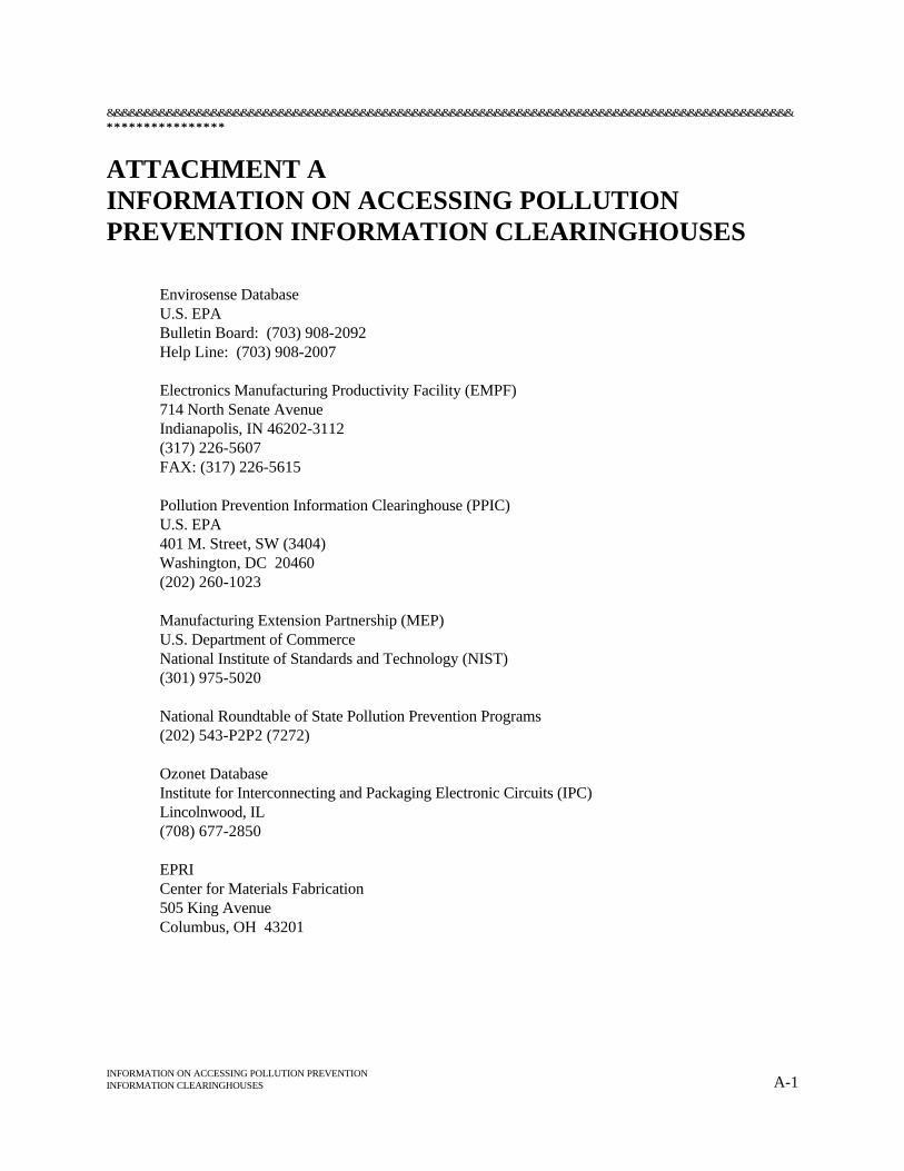
&&&&&&&&&&&&&&&&&&&&&&&&&&&&&&&&&&&&&&&&&&&&&&&&&&&&&&&&&&&&&&&&&&&&&&&&&&&&&&&&&&&&&&&&&&&&********************************
INFORMATION ON ACCESSING POLLUTION PREVENTIONINFORMATION CLEARINGHOUSES A-1
ATTACHMENT AINFORMATION ON ACCESSING POLLUTIONPREVENTION INFORMATION CLEARINGHOUSES
Envirosense DatabaseU.S. EPABulletin Board: (703) 908-2092Help Line: (703) 908-2007
Electronics Manufacturing Productivity Facility (EMPF)714 North Senate AvenueIndianapolis, IN 46202-3112(317) 226-5607FAX: (317) 226-5615
Pollution Prevention Information Clearinghouse (PPIC)U.S. EPA401 M. Street, SW (3404)Washington, DC 20460(202) 260-1023
Manufacturing Extension Partnership (MEP)U.S. Department of CommerceNational Institute of Standards and Technology (NIST)(301) 975-5020
National Roundtable of State Pollution Prevention Programs(202) 543-P2P2 (7272)
Ozonet DatabaseInstitute for Interconnecting and Packaging Electronic Circuits (IPC)Lincolnwood, IL (708) 677-2850
EPRICenter for Materials Fabrication505 King AvenueColumbus, OH 43201
********************************&&&&&&&&&&&&&&&&&&&&&&&&&&&&&&&&&&&&&&&&&&&&&&&&&&&&&&&&&&&&&&&&&&&&&&&&&&&&&&&&&&&&&&&&&&&&
A-2 Pollution Prevention in the Electronics Industry
Directions for How to Connect and Registeron the Enviro$en$e BBS via Modem
This document (which can be viewed in the BULLETINS section of Enviro$en$e’ BBS or downloaded fromthe UTILITIES directory of the Enviro$en$e (E$) Communications Network. It does not provide any detailsconcerning the World Wide Web (WWW) platform of Enviro$en$e.
Enviro$en$e (703/908-2092) TELEPHONE/ADDRESS INFORMATION:
HOTLINES:BBS: 703/908-2007WWW: 703/526-6956
CO-MANAGERS:BBS Platform: Louis Paley, 202/260-4640WWW Platform: Myles Morse, 202/260-3161
WWW/INTERNET ADDRESShttp://wastenot.inel.gov/envirosense/
I. THE ENVIRO$EN$E NETWORK:
The Enviro$en$e Communications Network is a free, public, interagency-supported system operated byEPA’s Office of Enforcement and Compliance Assurance and the Office of Research and Development. TheNetwork allows regulators, the regulated community, technologists, and the general public to shareinformation regarding: pollution prevention and innovative technology; environmental enforcement andcompliance assistance; laws, executive orders, regulations, and policies; points of contact for services andequipment; case studies; technical databases; and other related topics. The Network welcomes receipt ofenvironmental messages, information and data from any public or private person or organization.
II. SUMMARY INSTRUCTIONS—CONNECTING AND REGISTERING:
! Connect to E$ via a modem, using communications software set toconventional BBS settings, by calling:
(703) 908-2092
! Hit the RETURN/ENTER ("RETURN" is used hereafter to represent thiskey regardless of what your keyboard name is or where it is located) keytwice (2) if you want to get the default values for the screen;
! On successive screens, type your first name and hit RETURN; type yourlast name and hit RETURN; and type your password (if you have NOTregistered yet, make one up and make a note of it) and hit RETURN; and
&&&&&&&&&&&&&&&&&&&&&&&&&&&&&&&&&&&&&&&&&&&&&&&&&&&&&&&&&&&&&&&&&&&&&&&&&&&&&&&&&&&&&&&&&&&&********************************
INFORMATION ON ACCESSING POLLUTION PREVENTIONINFORMATION CLEARINGHOUSES A-3
! Register (first time only) and immediately receive access to the BBS for120 minutes per day;
- Type responses to the Registration questions. and hit RETURN tobegin using Enviro$en$e.
NOTE: When working within Enviro$en$e, one may generally abort scrolling by typing "N"; andone may generally return to a menu screen by hitting RETURN, either once or twice asneeded in a particular situation.
III. DETAILED INSTRUCTIONS—CONNECTING AND REGISTERING:
A. Modem Settings
Connecting to the Enviro$en$e BBS is done using a modem and communications software. The modem canbe either an internal or external model connected directly to your PC. The communications software (e.g.,CrossTalk , ProComm, QModem, etc.) is what allows you to access and control your modem. Your software1
needs to be set to the values noted below:
! Telephone Number - 703-908-2092
! Baud Rate - up to 14,400 BPS is supported (always select the highest speed which YOURmodem will support);
! Terminal Emulation - BBS, ANSI, VT-100, VT-102 (TTY for MacIntoshes), etc.;
! Data Bits - 8 (Eight);
! Stop Bits - 1 (One);
! Parity - None;
! Transfer Protocols - ZModem, YModem, XModem, HS/Lin, BiModem, ASCII (text filesonly). Zmodem is very efficient. You must select the same protocol that BOTH yourcommunications software and the BBS support so that they can "talk the same language;"and
! Error Correction/Data Compression Protocols - v.32, v.42 - and other older, hardware-dependent protocols are supported.
Refer to your communications software manual on how to set and save the communication parameters notedabove (these will generally be the default).
********************************&&&&&&&&&&&&&&&&&&&&&&&&&&&&&&&&&&&&&&&&&&&&&&&&&&&&&&&&&&&&&&&&&&&&&&&&&&&&&&&&&&&&&&&&&&&&
A-4 Pollution Prevention in the Electronics Industry
B. Registration Procedure (first time only)
After you tell your software to dial in, a connection should be established and you should see the openingscreen for the Enviro$en$e BBS.
! Accept the default settings by hitting "RETURN" twice;
! Type in your first name, hit RETURN; type in last name, and hit RETURN;
! ES checks to see if you are already registered; if you are not registered, type "C" to registerand hit RETURN;
! Respond to each of the questions regarding name and address information and hit RETURNrepeatedly until you are sent to the "List of Bulletins";
! Read the bulletins, and exit to E$' "System Menu";
! Set the desired "file transfer protocol" (matching it to whatever you set on your PC) bytyping "S(et) File Transfer Protocol" at the System Menu and hit RETURN;
! Type "V(iew) Current Settings" to confirm your answers and settings and hit RETURN;
! Type "C(hange) Settings" if any need to be changed; and
! Type "Q" to exit back to the System Menu.
C. Initial E$ Use
! ENJOY USING Envirosense by taking the following steps:
- Conduct file (document) searches ("S");- Look at directories and file ("F");- Look at new files ("N");- Upload files ("U");- Download files ("D");- Read or leave messages ("M")- Read bulletins ("B"); or- Go through the door ("O") to access one of several databases.
Additional help is available on-line by typing "H" at almost any BBS area (e.g., type "S", then "H" inresponse to the "Text to Scan For" question). Also read the help bulletins (in BULLETINS) or download thefiles from the Utilities directory (#160). These bulletins explain how to connect and register, find and view,convert to text, compress, and uncompress, download .TXT and .ZIP files, and upload files. The titles of the2
files are: "CONREGWP.TXT," "FINDVIEW.TXT," "CONVCOMP.TXT" "DNLDTXWP.TXT,""DNLDZPWP.TXT," and "UPLOADWP.TXT."
&&&&&&&&&&&&&&&&&&&&&&&&&&&&&&&&&&&&&&&&&&&&&&&&&&&&&&&&&&&&&&&&&&&&&&&&&&&&&&&&&&&&&&&&&&&&********************************
INFORMATION ON ACCESSING POLLUTION PREVENTIONINFORMATION CLEARINGHOUSES A-5
The mention of any software products by name is not an official endorsement but used for illustrative purposes only.1
The PK commands for the files PKZIP.EXE and PKUNZIP.EXE work very similarly to DOS' copy command. You must2
be at the DOS prompt in order to use them. To view details on how to use either command, simply type the commandPKZIP or PKUNZIP at the DOS prompt and hit RETURN. The files will automatically go into help mode and give you abrief explanation of how they work. If a user needs more direction, there is full explanation included in the PKZ204G.EXEfile. Type PKZ204G.EXE file at the DOS prompt to expand the file and read the instruction files. Refer specifically to thehelp file called HINTS.TXT.


ATTACHMENT B
SURVEY

MAILING LIST FOR FUTURE PUBLICATIONS
Name: Organization:
Position: Address:
Phone:
Fax:
SURVEY:
DID YOU FIND THIS MANUAL USEFUL?
Please help us by answering the following questions:
A. PROFILE OF YOUR ORGANIZATION
( ) Trade Association ( ) Business ( ) Government Office
( ) Other
What product or service does your business/organization provide?
How old is your business/organization? years
How many employees work in your business/organization?
B. TRAINING NEEDS
U.S. EPA and SEMARNAP plan to add sections to this manual or develop new manuals for other industries in the border area. Whichindustries should be addressed next?
( ) Textiles/Apparel ( ) Other
What type of training would you attend?
( ) Technical Workshops ( ) General Training ( ) None ( ) Other
U.S. EPA and SEMARNAP are considering holding training sessions on "pollution prevention."
What information would be useful to you in this area?
C. USEFULNESS OF MANUAL
Did you find the format of this manual useful? ( ) Yes ( ) No
Did you find its content useful? ( ) Yes ( ) No
How would you improve it?
What other information should be included?
44 44 44 44 44 44 44 (fold here) 44 44 44 44 44 44 44
Who else should receive this manual?
Name:
Address:
D. ADDITIONAL COMMENTS
Please provide any additional comments on this manual and its usefulness.
Please fold on the dotted line and mail. If you have any questions regarding this publication or would like additional information, youmay contact U.S. EPA (214) 665-2258, or SEMARNAP (52)5 553-9928.
44 44 44 44 44 44 44 (fold here) 44 44 44 44 44 44 44
- - - - -Place
StampHere
- - - - -
ROBERT D. LAWRENCE (6EN-XP)POLLUTION PREVENTION COORDINATORU.S. EPA REGION 61445 ROSS AVENUEDALLAS TX 75202
(Place tape here)