developing an innovative field expedient fracture ... · ornl/tm-2008/155. developing an innovative...
TRANSCRIPT
ORNL/TM-2008/155
Developing an Innovative Field Expedient Fracture Toughness Testing Protocol for Concrete Materials
September 2008
Prepared by John Jy-An Wang, Ken C. Liu, Dan Naus Oak Ridge National Laboratory

DOCUMENT AVAILABILITY
Reports produced after January 1, 1996, are generally available free via the U.S. Department of Energy (DOE) Information Bridge.
Web site http://www.osti.gov/bridge
Reports produced before January 1, 1996, may be purchased by members of the public from the following source.
National Technical Information Service
5285 Port Royal Road
Springfield, VA 22161
Telephone 703-605-6000 (1-800-553-6847)
TDD 703-487-4639
Fax 703-605-6900
E-mail [email protected]
Web site http://www.ntis.gov/support/ordernowabout.htm
Reports are available to DOE employees, DOE contractors, Energy Technology Data Exchange (ETDE) representatives, and International Nuclear Information System (INIS) representatives from the following source.
Office of Scientific and Technical Information
P.O. Box 62
Oak Ridge, TN 37831
Telephone 865-576-8401
Fax 865-576-5728
E-mail [email protected]
Web site http://www.osti.gov/contact.html
This report was prepared as an account of work sponsored by an agency of the United States Government. Neither the United States government nor any agency thereof, nor any of their employees, makes any warranty, express or implied, or assumes any legal liability or responsibility for the accuracy, completeness, or usefulness of any information, apparatus, product, or process disclosed, or represents that its use would not infringe privately owned rights. Reference herein to any specific commercial product, process, or service by trade name, trademark, manufacturer, or otherwise, does not necessarily constitute or imply its endorsement, recommendation, or favoring by the United States Government or any agency thereof. The views and opinions of authors expressed herein do not necessarily state or reflect those of the United States Government or any agency thereof.
iii
ORNL/TM-2008/155
Materials Science and Technology Division
DEVELOPING AN INNOVATIVE FIELD EXPEDIENT FRACTURE TOUGHNESS TESTING PROTOCOL FOR CONCRETE MATERIALS
John Jy-An Wang, Ken C. Liu, Dan Naus Oak Ridge National Laboratory
Date Published: September 2008
Prepared by
OAK RIDGE NATIONAL LABORATORY
P.O. Box 2008
Oak Ridge, Tennessee 37831-6285
managed by
UT-Battelle, LLC
for the
U.S. DEPARTMENT OF ENERGY
under contract DE-AC05-00OR22725

iv
iii
CONTENTS
Page
EXECUTIVE SUMMARY .........................................................................................................1 ABSTRACT ...............................................................................................................................2 1. BACKGROUND ....................................................................................................................3 2. INTRODUCTION...................................................................................................................5 3. SPIRAL NOTCH TORSION TEST (SNTT) SYSTEM ...........................................................7
3.1 Deformation Mechanism of the SNTT Configuration ........................................................7 3.2 SNTT Specimen Size Reduction ...................................................................................... 10
4. DEVELOPMENT OF TORQUE GRIPS FOR SNTT CONCRETE MATERIAL TESTING . 12 5. SNTT CONCRETE EXPERIMENTAL TEST RESULTS..................................................... 15
5.1 Material Properties of SNTT Mortar Samples .................................................................. 15 5.1.1 Mortar Mix Procedure............................................................................................... 15 5.1.2 Mortar Compressive Strength Testing ....................................................................... 15 5.1.3 Pilot Testing for Evaluating Concrete Tensile Strength ............................................. 16
5.2 SNTT Fracture Toughness Testing and Evaluation .......................................................... 22 6. CONCLUSIONS ................................................................................................................... 27 Acknowledgments ..................................................................................................................... 28 REFERENCES ......................................................................................................................... 28


v
LIST OF FIGURES
Figure Page
Figure 1 Brittle material fracture toughness test methods. ............................................................4 Figure 2 Concrete CT type specimens. ........................................................................................4 Figure 3 SNTT experimental set-up. ............................................................................................8 Figure 4 SNTT mortar test set-up. ..............................................................................................9 Figure 5 SNTT loading configuration. .........................................................................................9 Figure 6 SNTT FEM Models: (a) for the brittle material configuration, (b) for the ductile metallic
material configuration........................................................................................................ 10 Figure 7 Specimen size effect and SNTT transformation ........................................................... 11 Figure 8 SNTT Specimen miniaturization for A533B steel. ....................................................... 11 Figure 9 SNTT concrete grip fitting, (a) split-ring clamp, (b) square-end adapter base plate. ..... 12 Figure 10 The top split-ring grip design for SNTT concrete testing. .......................................... 13 Figure 11 The base adapter plate of grip design for SNTT concrete testing ................................ 14 Figure 12 Compression fractured samples, w/o Teflon insert, r. h. s. shows typical core of
fracture samples................................................................................................................. 16 Figure 13 Compression fractured samples, w/ Teflon insert at loading boundary. r.h.s. shows
typical fracture columns. ................................................................................................... 17 Figure 14 Chuck grip torsion test set-up. The fracture surface matches the principal tensile stress
contour. ............................................................................................................................. 18 Figure 15 Fracture surface along the 45° spiral groove. ............................................................. 19 Figure 16 Adapter plate design for the Chuck type A. ............................................................... 20 Figure 17 Adapter plate design for Chuck type B. ..................................................................... 21 Figure 18 Pure torsion test results. ............................................................................................. 22 Figure 19 SNTT test assembly and fractured SNTT sample. ...................................................... 23 Figure 20 SNTT mortar testing set-up with the protective shield. .............................................. 24 Figure 21 Fractured SNTT mortar sample shows classical tension brittle fracture characteristic.
.......................................................................................................................................... 26 Figure 22 Fractured surface, (right) at resolution ~50X ............................................................. 27 Figure 23 SNTT torsion test results, with notch depth (left) at 0.10-in, (right) at 0.075-in. ......... 27


vii
LIST OF TABLES
Table Page
Table 1 Test results of mortar fractured by SNTT method ......................................................... 25
1
EXECUTIVE SUMMARY
Failure of concrete structures is accompanied by cracking of concrete. Understanding and modeling of how and when concrete fails are not only critical for designing concrete structures, but are also important for developing new cement-based materials. Furthermore, to evaluate the response of concrete structures subjected to impact or impulsive loading, it is essential to know how cracks propagate under such dynamic loading conditions. Therefore, quantification of the fracture toughness (e.g., resistance to propagation of cracks) of concrete materials is the key to ensuring safe operation of concrete structures. High-strength concrete (HSC) was developed recently with compressive strengths reaching 25 ksi or higher to satisfy the need for high-rise reinforced concrete structures with reduced support column footprints to increase usable space. The drawback of HSC is that normally as the strength increases the fracture toughness decreases. Therefore, in applying HSC to modern buildings or infrastructure applications, it is desirable that the fracture toughness be known and incorporated into design criteria to provide improved long term durability and safety. In the absence of valid and economic test methods applicable for determining tensile properties of concrete, methods such as using a simple beam in three-point bending are utilized to provide an indirect measure of concrete tensile strength. Methods have however been developed for determining flexural toughness and first-crack strength of materials such as fiber-reinforced concrete as noted in ASTM C1018. However, the flexural toughness value developed is neither equivalent to, nor a rigorous substitution for the tensile fracture toughness value in the context of fracture mechanics theory. Furthermore, the specimen size requirement to obtain an valid Mode I fracture toughness (KIC) is extremely very large. A new testing protocol is proposed for determining tensile fracture toughness, KIC, for concrete materials that is also applicable to testing of composites such as fiber-reinforced concrete in laboratory or in the field.
The Spiral Notch Torsion Fracture Toughness Test (SNTT) was developed recently to determine the intrinsic fracture toughness (KIC) of structural materials. The SNTT system operates by applying pure torsion to uniform cylindrical specimens with a notch line that spirals around the specimen at a 45° pitch. KIC values are obtained with the aid of a three-dimensional finite-element computer code, TOR3D-KIC. The SNTT method is uniquely suitable for testing a wide variety of materials used extensively in pressure vessel and piping structural components and weldments. Application of the method to metallic, ceramic, and graphite materials has been demonstrated. One important characteristic of SNTT is that neither a fatigue precrack or a deep notch are required for the evaluation of brittle materials, which significantly reduces the sample size requirement. In this feasibility study we report results for a Portland cement-based mortar to demonstrate applicability of the SNTT method to cementitious materials. The estimated KIC of the tested mortar samples with compressive strength of 34.5 MPa was found to be 0.36 ± 0.017 MPa √m.

2
ABSTRACT The Spiral Notch Torsion Fracture Toughness Test (SNTT) was developed recently to determine the intrinsic fracture toughness (KIC) of structural materials. The SNTT system operates by applying pure torsion to uniform cylindrical specimens with a notch line that spirals around the specimen at a 45° pitch. KIC values are obtained with the aid of a three-dimensional finite-element computer code, TOR3D-KIC. The SNTT method is uniquely suitable for testing a wide variety of materials used extensively in pressure vessel and piping structural components and weldments. Application of the method to metallic, ceramic, and graphite materials has been demonstrated. One important characteristic of SNTT is that neither a fatigue precrack or a deep notch are required for the evaluation of brittle materials, which significantly reduces the sample size requirement. In this paper we report results for a Portland cement-based mortar to demonstrate applicability of the SNTT method to cementitious materials. The estimated KIC of the tested mortar samples with compressive strength of 34.45 MPa was found to be 0.360 ± 0.017 MPa √m
Keywordsfracture toughness, torsion testing, spiral notched-groove, miniature specimen, mixed-modes fracture, graphite, carbon, composites, mortar

3
1. BACKGROUND
The majority of infrastructure applications either directly or indirectly utilize reinforced concrete materials. Concrete is a tension-weak material, and its tensile strength is only 8-15% of its compressive strength. Since plain concrete structures almost always fail due to propagation of tensile cracks, fracture mechanics concepts can be directly applied to them. For engineering applications, the tensile-weak nature of concrete is usually reduced by using different types of reinforcement. Reinforcing steel bars are often considered to be hidden pillars of reinforced concrete structures. However, piles of twisted steel reinforcement exposed from fractured concrete structures lying in the ruin of the California earthquakes many years ago, such as in the recent 1989 San Francisco earthquake and 1994 Northridge earthquake, indicated that the virtue of reinforced concrete relies not only on the steel reinforcement but also on the fracture toughness of concrete matrix.
Fracture mechanics has allowed scientists and engineers to understand brittle fracture and to determine the conditions that cause a crack to grow in a brittle manner that can lead to failure of the structure. Fracture mechanics provides a measure of toughness, the extent to which a material can undergo deformation without fracturing. For a linear elastic material, the measurement and interpretation of fracture toughness is fairly straightforward. Concrete is not such a material; it is rather described as quasi-brittle, and only recently has research led to the development of fracture mechanics tests suitable for such quasi-brittle materials. In practice, engineering can benefit from the use of fracture criteria in design. However, fracture specifications will not be developed until there is a standard test method. In 2007, American Concrete Institute Committee 446, “Fracture Mechanics of Concrete,” launched an initiative to benchmark the potential testing protocols that can be used for evaluating concrete fracture toughness. Therefore, the concrete research community and industry conclude that standard methods are needed and it is time to begin work on its development.
Currently there is no consensus on a standard method for a direct measurement of concrete fracture toughness, KIC, with confidence. However, many fracture testing methods developed for brittle materials are utilized for estimating concrete fracture behavior as shown in Figure 1. The associated ASTM standards are: (1) D7313 using the disk-shaped compact tension geometry, (2) C1550 using centrally loaded round panel, and (3) C1609 using 3-point loading.
The testing methods indicated in Figure 1 all require deep notch samples, and due to quasi-brittle nature of concrete it normally requires a very large test sample as illustrated in Figure 2 to generate valid (or lower bound) fracture toughness. Moreover, large scatter of toughness data also has been exhibited from the conventional testing protocols. This mainly is due to size dependency and non-uniform crack front and inhomogeneous material characteristic of concrete. Therefore, to obtain valid fracture toughness data, the size requirement is extremely large using the above test methods.
In recent years, as high strength concrete is gaining importance, its fracture behavior is being studied with great care. The behavior of high strength concrete is closer to that described by linear theories of fracture and the concrete is more brittle than lower strength versions. The challenge is to provide an improved understanding of the fracture behavior of high-strength concrete so that its enhanced properties can be utilized more effectively while at the same time improving safety. The next challenge is related to the large size requirement of existing fracture

4
toughness approaches by development of a standardized test method that utilizes a more realistic specimen size. Both of these challenges can be addressed through the proposed technical approach that will potentially lead to improved codes of practice for the design of reinforced concrete structures.
Figure 1 Brittle material fracture toughness test methods.
Figure 2 Concrete CT type specimens.

5
2. INTRODUCTION
Intrinsic strength values are difficult to define for concrete and its family of composite materials including cement mortar because the measure of strength involves a multiplicity of interrelated elements, curing time and process history. The optimal strength of well-cured concrete may vary from batch to batch depending upon many factors, such as the ratio of mixture components, physical characteristics of aggregates, volume ratio between water and dry components, curing process, and environment in which the concrete was cured. Because of the irregularity in composition and external environmental factors, strength data obtained from laboratory tests may not genuinely reflect the strength of the concrete produced at construction sites.
The size effect of concrete is well-known and accounting for such effect into codes of practice on the design of reinforced concrete structures, such as, how to reconcile differences between laboratory test data and the properties of full scale structures remains a great challenge. The brief review presented below shows that there are several shortcomings in current methods for determining tensile strength and fracture toughness of concrete and cementitious materials.
Firstly, tensile strength could be best determined using a cylindrical specimen subjected to pure axial tension. However, due to difficulties in loading concrete in direct tension, the tensile strength of concrete is generally determined by a flexural loading test (modulus of rupture) or indirectly by a splitting-tensile test. For various types of concrete, the flexural test may overestimate the tensile strength of concrete by 50 to 100 percent, and the splitting-tensile test by 10-15 percent [1]. Secondly, three-point or four-point bend-test beams with a notch at the mid-span are widely used by researchers to determine fracture toughness. Criticism is the rigorousness of the linear assumption which cannot be physically verified. Typically, bend-test beam specimens [2] are made in the dimensions of approximately 150-mm (W, depth) by 700-mm (L, length) by 80-mm (B, thickness); the size is portable from field to laboratory but the thickness is far less than that required to fulfill the requirements of the theory of fracture mechanics. Thirdly, low-cost field fracture toughness testing of concrete materials is not practical and economically viable from the viewpoint of establishing equipment and test facilities.
Since 1961 when Kaplan initiated the study on the size effect of concrete fracture [3], many researchers have reported the experimental observations on the size effect of concrete fracture properties [4-5]. The size-effect law by Bazˇant [6] and the specific fracture energy GF proposed by RILEM [7-8] have further provided insight into size effects. However, it has been found that fracture energy depends on both size and geometry of the test specimen. Extensive experimental and theoretical studies have been conducted to understand the size effect mechanisms [9-10]. Xu and Wittmann [11-13] showed that local fracture energy varies with the width of the fracture process zone. As the crack front approaches the back end of a specimen, the fracture process zone becomes more and more confined and hence the local fracture energy decreases. It was shown that a local variation of the fracture energy leads to a size dependence of the global specific fracture energy. In general, experimental results reveal that the size effect of concrete testing has two phenomena: (1) for geometrically similar specimens, concrete strength decreases with increasing specimen size, and (2) both the specific fracture energy and fracture toughness increase with increasing specimen size and un-broken ligament length [3–6, 14]. Furthermore, it has been noted that the specimen thickness, as a size measurement, also influences the fracture
6
behavior of concrete. Thick specimens have higher constraint than that of thin specimens. In general, to obtain a valid plane-strain fracture toughness of metallic materials it requires large and thick specimens. This is because a large portion of the fracture energy is attributed to the plastic deformation (such as shear lip formation) for a small specimen testing, and this results in a large stress intensity factor and is highly non-conservative. For concrete materials, limited results have shown that the specific fracture energy increased with increasing specimen thickness and reached a plateau when the specimen thickness increased to about four times of the maximum aggregate size [15] (this seems to contradict the fracture toughness characteristic of metallic materials). Others showed no thickness effect if specimen thickness was much larger than the maximum grain size [16].
Fig. 1 illustrates conventional fracture toughness testing methods for brittle materials (such as concrete, graphite, or carbon composite), indicating that a test specimen machined with deep notch is required. An unconventional mode of tensile test is proposed herein for determining both the tensile strength and fracture toughness of concrete and its family of composites. This method applies a pair of opposing pure torsion forces on the ends of a cylinder specimen, so that the stress distribution on every cross section normal to the axis is identical, and the maximum tensile stress can be calculated unambiguously as in the case of pure tension. Post-mortem examinations of tested specimens show that the concept is theoretically sound and experimentally accurate. This method offers a number of ways to eliminate ambiguity and solve or avoid the inherent problems discussed above. Simplicity of the specimen is a major feature, which permits investigators to conduct both types of test using the same test equipment, procedure, and specimen design, with little or no modifications. Mode-I fracture toughness is obtained if the cylindrical specimen is fabricated with a shallow spiral groove on the surface having a pitch angle of 45°; thereby, it is called spiral notch torsion test (SNTT). In typical fracture toughness tests, the direction of crack propagation is unpredictable and often deflects in zigzags or a thumbnail pattern, resulting in large data scatter. When a rod specimen is twisted, the spiral notch provides a fracture mode for cracking to start, and the pure torsion load ensures that the crack will advance perpendicularly toward the central axis of the test specimen. Therefore, the SNTT methodology is expected to significantly reduce uncertainty in fracture toughness evaluation.
For SNTT method only the shallow surface notch is required for testing brittle materials. This will significantly reduces the specimen size as compared to the conventional test specimens shown in Fig. 1. Furthermore, the ability of SNTT to confine the plastic deformation within a thin plane provides the opportunity to investigate the interfacial material properties [3-6]; such application can be used to investigate the cohesion bounding at interface between the cement paste and the aggregate. SNTT test method is superior compared to the bend-beam testing, because (1) the size effect is minimized, (2) inherited high stress gradients from pure torsion (pure shear stress) field, (3) no free surface (normal to specimen axis) exists in the SNTT specimen geometry under the pure torsion loading, and (4) mixed mode fracture toughness values can be easily obtained by changing the pitch angle of the spiral line. SNTT testing can be performed in the field economically using low-cost test equipment and samples that have been cured in the same environment (e.g., removal of small diameter cores from structure).
7
3. SPIRAL NOTCH TORSION TEST (SNTT) SYSTEM
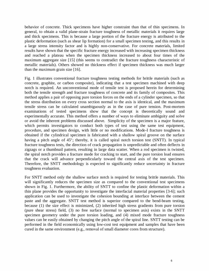
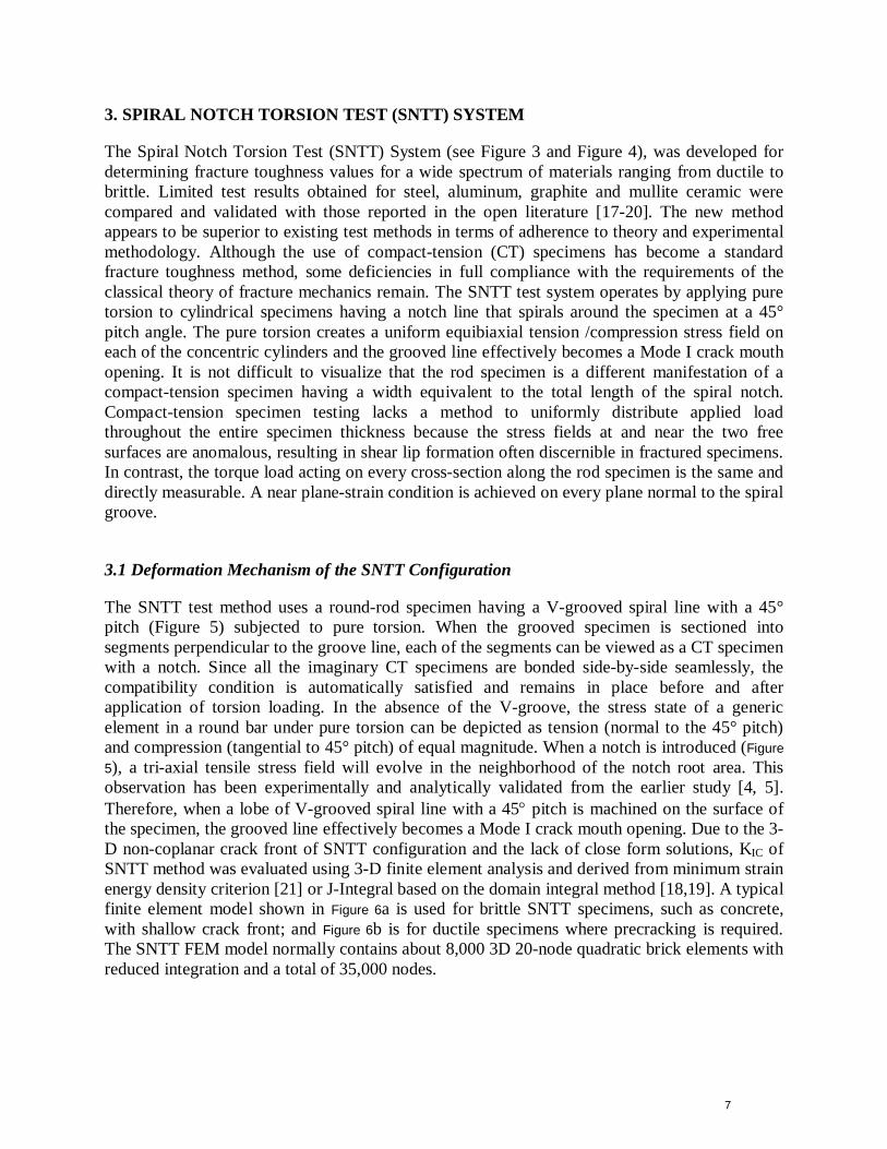
The Spiral Notch Torsion Test (SNTT) System (see Figure 3 and Figure 4), was developed for determining fracture toughness values for a wide spectrum of materials ranging from ductile to brittle. Limited test results obtained for steel, aluminum, graphite and mullite ceramic were compared and validated with those reported in the open literature [17-20]. The new method appears to be superior to existing test methods in terms of adherence to theory and experimental methodology. Although the use of compact-tension (CT) specimens has become a standard fracture toughness method, some deficiencies in full compliance with the requirements of the classical theory of fracture mechanics remain. The SNTT test system operates by applying pure torsion to cylindrical specimens having a notch line that spirals around the specimen at a 45° pitch angle. The pure torsion creates a uniform equibiaxial tension /compression stress field on each of the concentric cylinders and the grooved line effectively becomes a Mode I crack mouth opening. It is not difficult to visualize that the rod specimen is a different manifestation of a compact-tension specimen having a width equivalent to the total length of the spiral notch. Compact-tension specimen testing lacks a method to uniformly distribute applied load throughout the entire specimen thickness because the stress fields at and near the two free surfaces are anomalous, resulting in shear lip formation often discernible in fractured specimens. In contrast, the torque load acting on every cross-section along the rod specimen is the same and directly measurable. A near plane-strain condition is achieved on every plane normal to the spiral groove.
3.1 Deformation Mechanism of the SNTT Configuration
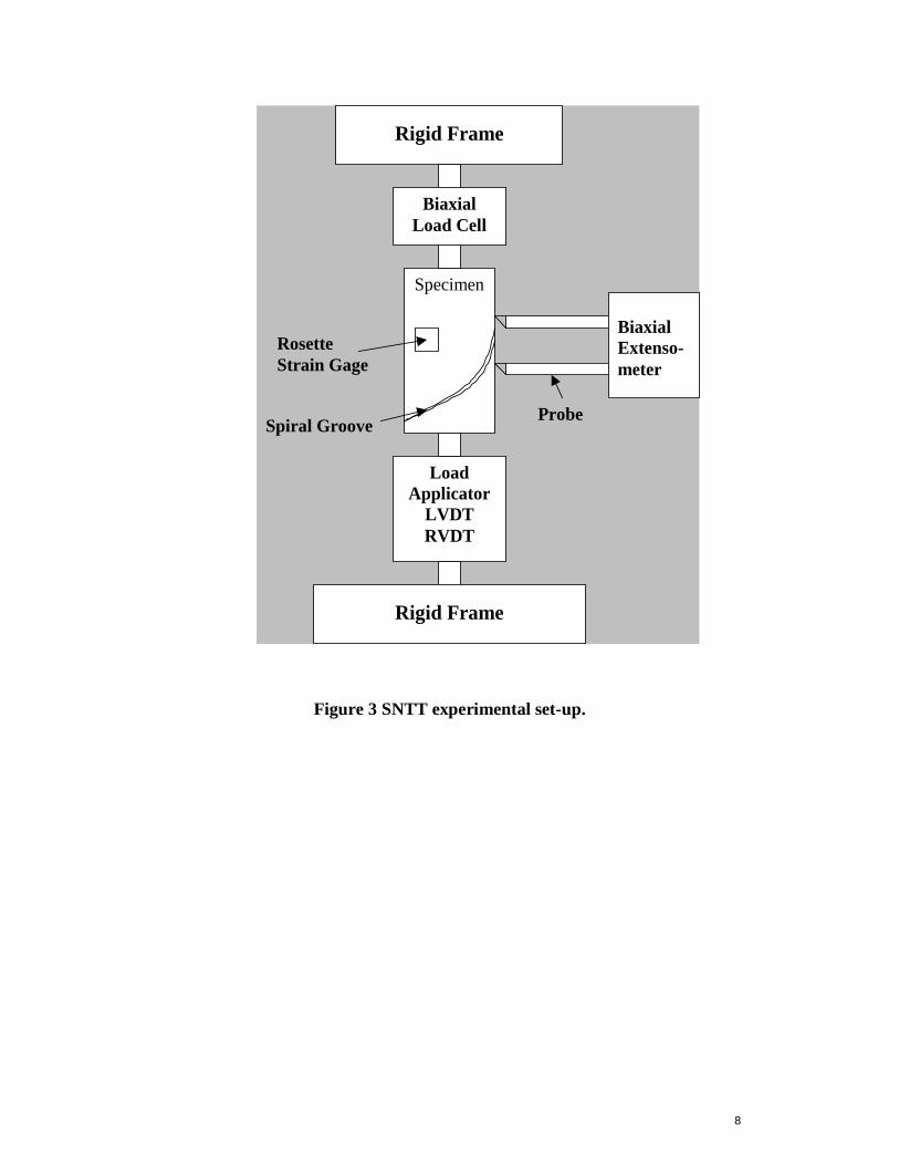
The SNTT test method uses a round-rod specimen having a V-grooved spiral line with a 45° pitch (Figure 5) subjected to pure torsion. When the grooved specimen is sectioned into segments perpendicular to the groove line, each of the segments can be viewed as a CT specimen with a notch. Since all the imaginary CT specimens are bonded side-by-side seamlessly, the compatibility condition is automatically satisfied and remains in place before and after application of torsion loading. In the absence of the V-groove, the stress state of a generic element in a round bar under pure torsion can be depicted as tension (normal to the 45° pitch) and compression (tangential to 45° pitch) of equal magnitude. When a notch is introduced (Figure 5), a tri-axial tensile stress field will evolve in the neighborhood of the notch root area. This observation has been experimentally and analytically validated from the earlier study [4, 5]. Therefore, when a lobe of V-grooved spiral line with a 45° pitch is machined on the surface of the specimen, the grooved line effectively becomes a Mode I crack mouth opening. Due to the 3-D non-coplanar crack front of SNTT configuration and the lack of close form solutions, KIC of SNTT method was evaluated using 3-D finite element analysis and derived from minimum strain energy density criterion [21] or J-Integral based on the domain integral method [18,19]. A typical finite element model shown in Figure 6a is used for brittle SNTT specimens, such as concrete, with shallow crack front; and Figure 6b is for ductile specimens where precracking is required. The SNTT FEM model normally contains about 8,000 3D 20-node quadratic brick elements with reduced integration and a total of 35,000 nodes.
8
Figure 3 SNTT experimental set-up.
Specimen Biaxial Extenso-meter
Probe Spiral Groove
Rosette Strain Gage
Biaxial Load Cell
Load Applicator
LVDT RVDT
Rigid Frame
Rigid Frame
9
Figure 4 SNTT mortar test set-up.
Figure 5 SNTT loading configuration.
Torque
45° spiral groove
Pure shear stress
Principal tensile stress

10
Figure 6 SNTT FEM Models: (a) for the brittle material configuration, (b) for the ductile metallic material configuration.
3.2 SNTT Specimen Size Reduction The CT specimen, as shown in the upper area of Figure 7, has been widely used in existing fracture toughness test methods because the general consensus indicates that it is the next-best basic configuration that nearly conforms to the strict requirements of the classical theory of fracture mechanics. Despite the simplification, the theoretical conditions (i.e., the conditions required to achieve uniformly distributed applied stress over the thickness and plane-strain condition) can never materialize as long as the free surfaces exist at both ends. The end effects will be further amplified when the thickness decreases to a thin plate, as shown in Figure 7. A compounded problem is that an increase in specimen thickness will automatically accompany an increase in specimen length and width in order to maintain specimen rigidity under load. Miniaturization is an important goal of the SNTT method. This is made possible because the KIC values determined by the SNTT method are virtually independent of specimen size. A review of the stress and strain fields in a CT specimen indicates that the key information needed for determining the KIC values is manifested within a small region near the crack tip; therefore, the rod specimen can be miniaturized substantially without the loss of general validity (Figure 7). The purpose of the vast volume of the material outside the critical zone in conventional samples is to poise the ideal far field of stress and to provide a means to accommodate loading devices. This redundancy is eliminated for the optimum condition in the round rod specimen; therefore, the specimen miniaturization is achieved.
SNTT is a unique feature allowing miniaturization of test specimens (see Figure 8) to appropriate sizes. This makes the test method economically attractive and test equipment portable for on-site testing. Furthermore, for brittle materials only a shallow notch is needed, this further reduces the specimen size required for generating a valid KIC test.
(a) Shallow crack (b) Deep fatigue crack

11
Based on the above, the SNTT approach is considered to be superior to the conventional approaches for concrete fracture mechanics testing. Our primary objective is to show feasibility of applying SNTT to develop valid fracture mechanics data for concrete materials that can lead to improved design and safety of reinforced concrete structures. To this end, the following tasks are planned:
Figure 7 Specimen size effect and SNTT transformation
Figure 8 SNTT Specimen miniaturization for A533B steel.
Plane Strain Plane Stress
Key Information
t1 t2
KICKC
Load
Spiral Notch Spiral Notch Test SampleTest Sample
Load
KIC ≠ KC
Torque
Thickness, t
KC
KIC

12
4. DEVELOPMENT OF TORQUE GRIPS FOR SNTT CONCRETE MATERIAL TESTING
Due to the quasi-brittle nature of concrete materials, the developed end-grip fittings for SNTT testing protocol needs to be modified for efficiently transmitting the torque to the concrete composite sample without damaging the sample at the grip-ends. Several fittings were designed and evaluated: (1) chuck type grip-ends coupling with rubber-mesh wire insert, and (2) an integrated grip formed with a split-ring clamp and a square base. In the second grip-ends design epoxy added at interface between sample and grip fills the gap present at the interface between sample and the split-ring clamp and provides improved resistance to interfacial slip. The SNTT concrete integrated grip design is illustrated in Figure 9 and the details of the grip design specifications are shown in Figure 10 and Figure 11. While the first option a more straightforward and economic approach was found to be difficult to properly align the rod sample and slippage occurred frequently during the test. Therefore, the second option was preferred and used in carrying out the mortar material fracture toughness evaluation.
Figure 9 SNTT concrete grip fitting, (a) split-ring clamp, (b) square-end adapter base plate.

13
Figure 10 The top split-ring grip design for SNTT concrete testing.

14
Figure 11 The base adapter plate of grip design for SNTT concrete testing

15
5. SNTT CONCRETE EXPERIMENTAL TEST RESULTS
5.1 Material Properties of SNTT Mortar Samples
A pilot study of applying SNTT to a mortar material was carried out. The 40.6-mm-diameter by 177.8-mm-long SNTT test samples were made from a Portland cement-based mortar. The compression test samples of 50.8-mm cubic block were made from the same batch of the mortar material. The details of the material preparation are described below.
5.1.1 Mortar Mix Procedure The mortar used for specimen fabrication was prepared by first blending the cement and sand together followed by addition of water. Mixing was by hand until the mix assumed a uniform consistency (minimum period of five minutes). Following mixing, twelve 50.8-mm cubes, nine cylinders 40.6-mm diameter by 177.8-mm long, and four cylinders 76.2-mm diameter by 152.4-mm long were cast. Cube specimens were cast into brass molds and cylindrical specimens into polyvinylchloride molds. The specimens were cast in three layers with rodding used to consolidate each layer prior to addition of the next layer of material. Following casting, the specimens were sealed with plastic until they were removed from the molds the following week. Following removal from the molds, the specimens were placed into a water bath for additional curing. Approximately 2 months after casting the specimens were removed from the water bath and air dried until tested.
The cement used to fabricate the specimens was ASTM C150 Type II and V. The sand was primarily a siliceous material having a moisture content of 6.9% (by weight) and a specific gravity of 2.62. Maximum sand particle size was approximately 4 mm. The weights of the cement, sand, and water used in the mortar mix were 2.72 kg, 10.89 kg, and 1.63 kg, respectively.
5.1.2 Mortar Compressive Strength Testing
Compression tests were carried out to determine the mortar strength. An example of the effect of constraint (or lack of) is illustrated for testing a mortar cubic in compression. The compression testing was conducted on 50.8-mm (2-in.) cubic blocks. Two sets of boundary conditions were applied to the tested samples; (1) sample directly in contact with the compression plate, which is the conventional approach, and (2) Teflon plates were inserted at interfaces between the sample and loading frame, where Teflon insert acts as lubricant at the loading interface to reduce the friction induced shear force at loading interfaces. The test results indicate that the mortar sample without Teflon inserts has compressive strength 34.45 MPa (5000 psi), which is about twice that from tested sample with Teflon insert. The fractured samples are shown in Figure 12 and Figure 13 for loading without Teflon insert and with Teflon insert, respectively. From postmortem examination, the fracture surfaces of samples w/ Teflon inserts fractured parallel to the loading direction and appear to be a Poisson effect induced tension failure; while for samples tested without the Teflon insert a shear-type failure was observed as noted by the inclined fracture surface, this is mainly due to high friction shear resistance that exists at the loading interface. Thus, the friction induced shear resistance at the boundary has significant impact on the compressive strength evaluation. The sensitivity of the strength to the magnitude of friction is

16
one of the shortcomings of the standard compression test. This effect is due to variations in triaxiality, which in turn affects the susceptibility to crack penetrations. [22]
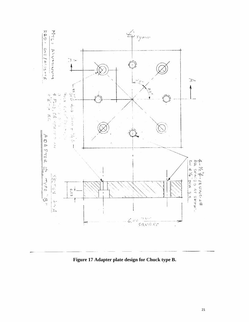
5.1.3 Pilot Testing for Evaluating Concrete Tensile Strength As discussed in the Introductory Section, we propose to use pure torsion mode on the circular rod sample to evaluate the tensile strength of concrete composite materials. A pilot testing protocol was developed accordingly, which uses Option 1 gripping procedure, with chuck grip-ends design fitting, to carry out the pure torsion test. The test set-up is shown in Figure 14, where a set of rubber/mesh-wire and the anchor clamp was tightened to the ends of specimen. The added rubber/mesh wire/clamp set-up provides (1) protection to prevent the sample being crushed at the grip-ends and (2) sufficient friction resistance at loading interface to transmit the torque to the sample during pure torsion testing. The postmortem examination indicates that the fracture surface of the fractured mortar samples under pure torsion aligns with 45 spiral pitch angle, which is the principal tension stress contour, shown in Figure 14. The details of the fracture surface along the spiral groove is shown in Figure 15. The detailed design specifications for the adapter plates that holding the chucks are shown in Figure 16 and Figure 17. The fracture torque was 748 N-m (550 lb-in), shown in Figure 18. The estimated maximum shear stress on the sample surface is 725 psi, and the associated maximum tension strength is 725 psi. This pilot testing has validated the feasibility of using pure torsion testing to evaluate the tensile strength of concrete materials.
Figure 12 Compression fractured samples, w/o Teflon insert, r. h. s. shows typical core of fracture samples.

17
Figure 13 Compression fractured samples, w/ Teflon insert at loading boundary. r.h.s. shows typical fracture columns.
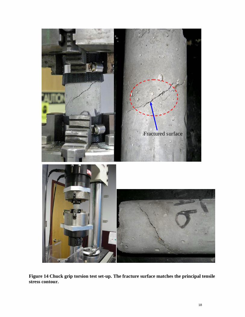
18
Figure 14 Chuck grip torsion test set-up. The fracture surface matches the principal tensile stress contour.
Fractured surface

19
Figure 15 Fracture surface along the 45° spiral groove.

20
Figure 16 Adapter plate design for the Chuck type A.
21
Figure 17 Adapter plate design for Chuck type B.

22
Figure 18 Pure torsion test results.
5.2 SNTT Fracture Toughness Testing and Evaluation Torsion tests were performed in a closed-loop controlled, electro-hydraulic, biaxial testing system shown in Figure 3 and Figure 4. Shear strain was measured using a biaxial strain extensometer and a Rosette strain gage for cross calibration. Pure torsion was achieved with a zero axial force in control. Shallow surface notches were applied to 177.8-mm (7-in) long mortar samples having 40.6 mm (1.6-in) diameter. Pre-cracking for brittle material of SNTT sample is not required, which was further validated from the postmortem investigation of SNTT fractured mortar samples. The Option 2 gripping procedure was used in SNTT mortar fracture toughness evaluation. The SNTT sample with Option 2’s end-grip assembly is shown in Figure 19(a), where a full lobe of 45-pitch angle spiral-shallow groove was engraved onto a 177.8-mm (7 inch) long mortar sample with 40.8-mm (1.6 in.) diameter. The SNTT assembly is ready to be placed directly into the adapters of the torsion testing frame without additional effort of aligning the test set-up as required by an Option 1’s procedure. A typical fractured surface profile of a tested SNTT mortar sample is shown in Figure 19(b). The overall set-up and the protective shield for SNTT mortar testing is shown in Figure 20.
The fracture-torque results of the SNTT mortar sample are listed in Table 1, the associated notch-depth ranges (initial crack length) of the SNTT mortar samples are also provided. The variation of the fracture torques observed from the tested SNTT mortar samples appears to be consistent with the associated notch-depth variation. Based on fracture torque of 50.85 N-m (450 lb-in) and notch depth of 1.9-mm (0.075-in), with Young’s modulus of 32.2 GPa [23] and Poisson’s ratio of 0.2, the Mode I fracture toughness, KIC, of the mortar sample is estimated as 0.36 ± 0.017 MPa √m, and the J-integral value (or Gf) is estimated as 3.88 ± 0.38 N/m. This value is compatible with that listed in Table 1 of reference 23 and in Table 2 of reference 16, and appears to be the lowest bound.
0
100
200
300
400
500
600
0 5 10 15 20
Rotation Angle, Deg.
Torq
ue L
oad.
lb-in
.

23
(a) (b)
Figure 19 SNTT test assembly and fractured SNTT sample.

24
Figure 20 SNTT mortar testing set-up with the protective shield.

25
Table 1 Test results of mortar fractured by SNTT method
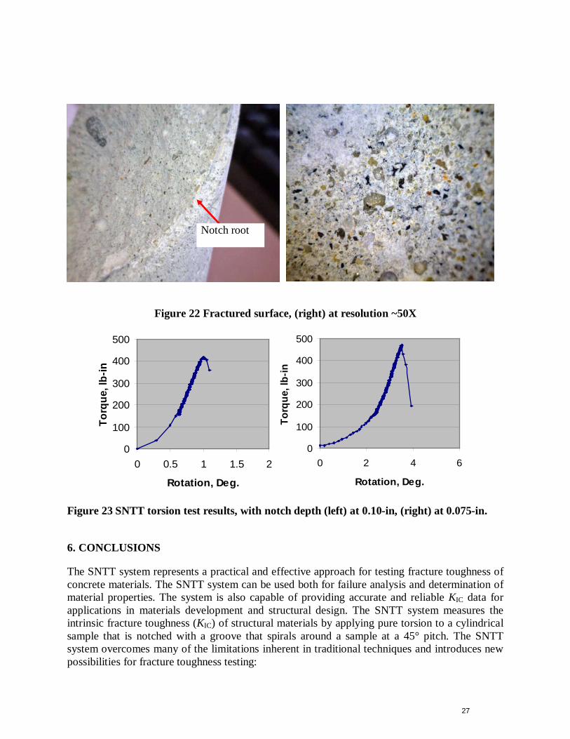
The fractured surface of tested SNTT samples shows a classical tensile brittle fracture feature, as illustrated in Figure 21 and Figure 22. The pure torsion test result of SNTT mortar sample is shown in Figure 23, for the sample that failed at 564 N-m (415 lb-in) torque. The initial low-load rotation, up to 204 N-m (150 lb-in), was due to initial gaps between the square-torque ends of the SNTT assembly and the torque-coupling adapter-ends of the loading frame. Due to the limited experimental data obtained, no uncertainty analysis was carried out. However, the long crack front and the stringent near plane-strain condition should yield less uncertainty compared to conventional test methods. The characteristic features of the uniform crack fronts discerned in tested torsion samples appear to support the above statement.

26
Figure 21 Fractured SNTT mortar sample shows classical tension brittle fracture characteristic.
27
Figure 22 Fractured surface, (right) at resolution ~50X
Figure 23 SNTT torsion test results, with notch depth (left) at 0.10-in, (right) at 0.075-in.
6. CONCLUSIONS
The SNTT system represents a practical and effective approach for testing fracture toughness of concrete materials. The SNTT system can be used both for failure analysis and determination of material properties. The system is also capable of providing accurate and reliable KIC data for applications in materials development and structural design. The SNTT system measures the intrinsic fracture toughness (KIC) of structural materials by applying pure torsion to a cylindrical sample that is notched with a groove that spirals around a sample at a 45° pitch. The SNTT system overcomes many of the limitations inherent in traditional techniques and introduces new possibilities for fracture toughness testing:
0
100
200
300
400
500
0 2 4 6
Rotation, Deg.
Torq
ue, l
b-in
0
100
200
300
400
500
0 0.5 1 1.5 2
Rotation, Deg.
Torq
ue, l
b-in
Notch root

28
It conforms to the classical theory of fracture mechanics. Allows miniaturization of test specimen to appropriate sizes, which make the test method
economically attractive and test equipment portable for on-site testing. Furthermore, for brittle material only the shallow notch is needed, this further reduces the
specimen size required for generating a valid KIC test. Other unique characteristics of SNTT approaches include:
Due to near plane-strain and the axisymmetric constraint inherent in SNTT method, the crack front must propagate perpendicularly toward the specimen axis along the right conoids. This results in a uniform crack front and less data scatter.
Under pure torsion loading, in the absence of hydrostatic pressure component; no volume change (or sample volume consolidation) occurs in the global sense. This also avoids inducing damage to concrete sample at grip-ends (or load transferred sites) during testing.
Mode I and Mode III combined mixed-mode testing can be easily implemented by varying the pitch angle of the notch line.
Based on the above, the SNTT test method appears to be an improved approach for concrete fracture mechanics evaluation.
Acknowledgments
The authors gratefully acknowledge E. Lara-Curzio, P. J. M. Monteiro, and J. G. Merkle for reviewing this report. The research was sponsored by the ORNL LDRD Seed Money Program under contract DE-AC05-00OR22725 with UT-Battelle, LLC.
REFERENCES
[1] P.K. Mehta and P.J.M. Monteiro, Concrete-Microstructure, Properties, and materials, Third Editio120n, The McGrow-Hill Companies, New York, 2000.
[2] ASTM Test Method for Plane-Strain Fracture Toughness of Metallic Materials (E399). [3] M.F. Kaplan, Crack propagation and the fracture of concrete, ACI J. 58 (1961) 591– 610. [4] D.D. Higgins, J.E. Bailey, Fracture measurements on cement paste, J. Mater. Sci. 11 (1976)
1995– 2003. [5] P. Nallathambi, B.L. Karihaloo, B.S. Heaton, Effect of specimen and crack sizes,
water/cement ratio and coarse aggregate texture upon fracture toughness of concrete, Mag. Concr. Res. 36 (129) (1984) 227– 236.
[6] Z.P. Bazˇant, Size effect in blunt fracture: concrete, rock, metal, J. Eng. Mech. ASCE 110 (4) (1984) 518– 535.
[7] A. Hillerborg, Results of three comparative test series for determining the fracture energy GF of concrete, Mater. Struct. 18 (1985) 33– 39.
[8] RILEM TC-50 FMC, Determination of the fracture energy of mortar and concrete by means of three-point bend tests on notched beams, Mater. Struct. 18 (1985) 287– 290 (endorsed May 1993).

29
[9] A. Carpinteri, B. Chiaia, Multifractal scaling law for the fracture energy variation of concrete structures, in: F.H. Wittmann (Ed.), Fracture Mechanics of Concrete Structures (Proc. FRAMCOS-2), AEDIFICATIO Publishers, Freiburg, Germany, 1995, pp. 581– 596.
[10] F.H. Wittmann, H. Mihashi, N. Nomura, Size effect on fracture energy of concrete, Eng. Fract. Mech. 35 (1990) 107– 115.
[11] X.Z. Hu, F.H. Wittmann, Fracture energy and fracture process zone. Mater Struct 1992;25:319–26.
[12] K. Duan, X.Z. Hu, FH. Wittmann, Thickness effect on fracture energy of cementitious materials. Cem Concr Res 2003;33(4):499–507.
[13] K. Duan, X.Z. Hu, F.H. Wittmann, Size effect on specific fracture energy of concrete. Cem Concr Res 2007:74:87-96.
[14] B. Trunk, F.H. Wittmann, Experimental investigation into the size dependence of fracture mechanics parameters. Mihashi H, Rokugo K. (Eds.), Fracture Mechanics of Concrete Structures (Proc. FRAMCOS-3), AEDIFICATIO Publishers, Freiburg, Germany, 1998, pp. 1937– 1948.
[15] F.H. Wittmann, Fracture process zone and fracture energy, in: Z.P. Bazˇant (Ed.), Fracture Mechanics of Concrete Structures (Proc. FRAMCOS-1), Elsevier, Amsterdam, 1992, pp. 391–403.
[16] S. Mindess, J.S. Nadeau, Effect of notch width on KIC for mortar and concrete, Cem. Concr. Res. 6 (4) (1976) 529– 534.
[17] J.A, Wang, K.C. Liu, D.E. McCabe, and S.A. David, Using Torsion Bar Testing to Determine Fracture Toughness, KIC. Journal of Fatigue & Fracture for Engineering Materials and Structure, Vol. 23, pp 45-56, 2000.
[18] J.A, Wang, K.C. Liu, D.E. McCabe, An Innovative Technique for Measuring Fracture Toughness of Metallic and Ceramic Materials. Fatigue and Fracture Mechanics: 33rd Volume, ASTM STP 1417, W. G. Reuter and R. S. Piascik, Eds., pp. 757-770, December 2002.
[19] J.A, Wang and K.C. Liu, A New Approach to Evaluate Fracture Toughness of Structural Materials. Journal of Pressure Vessel Technology, Vol. 126, pp 534-540, November, 2004.
[20] J.A. Wang, I.G. Wright, M.J. Lance, K.C. Liu, A New Approach for Evaluating Thin Film Interface Fracture Toughness. Material Science and Engineering A, 426 (2006), 332-345.
[21] G. C., Sih, Strain Energy Density Factor Applied to Mixed Mode Crack Problem, International Journal of Fracture, 1974, Vol. 10, pp. 305-321.
[22] J. Glucklich, On the compression failure of plane concrete. T. & A.M. Report No. 215, March 1962, Department of Theoretical and Applied Mechanics, University of Illinois.
[23] D.N. Nwokoye, Assessment of the elastic moduli of cement paste and mortar phases in concrete from pulse velocity tests, Cem. Concr. Res. 4 (1974) 641–655.