developing and validating reservoir pressure ... - …
TRANSCRIPT

DEVELOPING AND VALIDATING RESERVOIR PRESSURE MANAGEMENT AND PLUME CONTROL STRATEGIES IN THE WILLISTON BASIN THROUGH A BRINE EXTRACTION AND
STORAGE TEST (BEST) – PHASE IIDE-FE0026160
Mastering the Subsurface Through Technology Innovation & Collaboration: Carbon Storage & Oil & Natural Gas Technologies Review Meeting
August 17, 2016
John A. HamlingPrincipal Engineer
© 2016 University of North Dakota Energy & Environmental Research Center.
DisclaimerThis presentation was prepared as an account of work sponsored by an agency of the United States Government. Neither the United States Government, nor any agency thereof, nor any of their employees, makes any warranty, express or implied, or assumes any legal liability or responsibility for the accuracy, completeness, or usefulness of any information, apparatus, product, or process disclosed or represents that its use would not infringe privately owned rights. Reference herein to any specific commercial product, process, or service by trade name, trademark, manufacturer, or otherwise does not necessarily constitute or imply its endorsement, recommendation, or favoring by the United States Government or any agency thereof. The views and opinions of authors expressed herein do not necessarily state or reflect those of the United States Government or any agency thereof.
LEGAL NOTICE: This work was prepared by the Energy & Environmental Research Center (EERC), an agency of the University of North Dakota, as an account of work sponsored by the U.S. Department of Energy (DOE) National Energy Technology Laboratory. Because of the research nature of the work performed, neither the EERC nor any of its employees makes any warranty, express or implied, or assumes any legal liability or responsibility for the accuracy, completeness, or usefulness of any information, apparatus, product, or process disclosed or represents that its use would not infringe privately owned rights. Reference herein to any specific commercial product, process, or service by trade name, trademark, manufacturer, or otherwise does not necessarily constitute or imply its endorsement or recommendation by the EERC.
AcknowledgmentsThis material is based upon work supported by the U.S. Department of Energy
National Energy Technology Laboratory under Award No. DE-FE0026160.
Thank You Project Partners
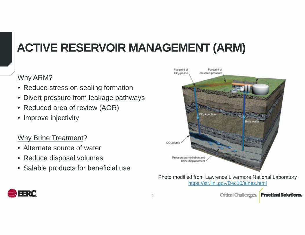
ACTIVE RESERVOIR MANAGEMENT (ARM)
Why ARM?• Reduce stress on sealing formation• Divert pressure from leakage pathways• Reduced area of review (AOR)• Improve injectivity
Why Brine Treatment?• Alternate source of water• Reduce disposal volumes• Salable products for beneficial use
5
Photo modified from Lawrence Livermore National Laboratory https://str.llnl.gov/Dec10/aines.html
6
BENEFITS STATEMENT
This project is expected to result in the development of engineering strategies/approaches to quantitatively affect changes in differential formation pressure and to monitor, predict, and manage differential pressure plume movement in the subsurface for future CO2 saline storage projects. Additionally, the brine treatment technology evaluation is expected to provide valuable information on the ability to produce water for beneficial use. The results derived from implementation of the project will provide a significant contribution to the U.S. Department of Energy’s (DOE’s) Carbon Storage Program goals. Specifically, this project will support Goals 1 and 2 by validating technologies that will improve reservoir storage efficiency, ensure containment effectiveness, and/or ensure storage permanence by controlling injected fluid plumes in a representative CO2 storage target. Geologic characterization of the target horizons will provide fundamental data to improve storage coefficients related to the respective depositional environments investigated, directly contributing to Goal 3. In addition, this project will support Goal 4 by producing information that will be useful for inclusion in DOE best practices manuals.
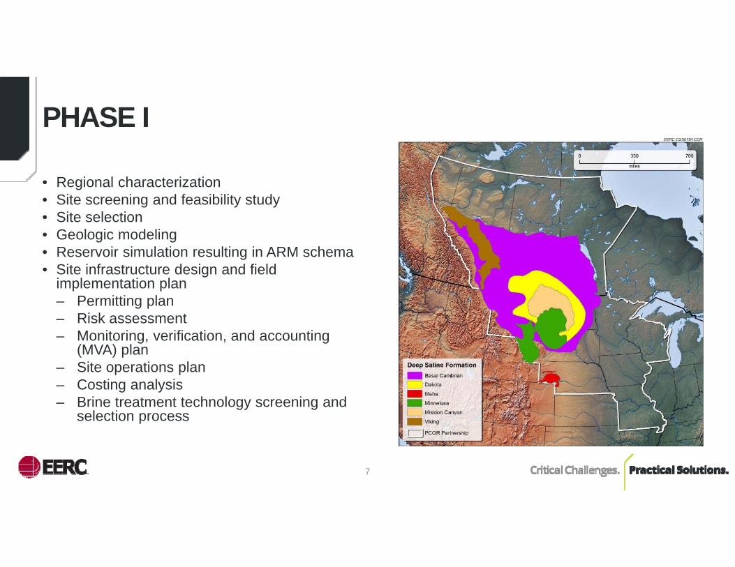
• Regional characterization• Site screening and feasibility study• Site selection• Geologic modeling • Reservoir simulation resulting in ARM schema• Site infrastructure design and field
implementation plan– Permitting plan– Risk assessment– Monitoring, verification, and accounting
(MVA) plan – Site operations plan– Costing analysis– Brine treatment technology screening and
selection process
7
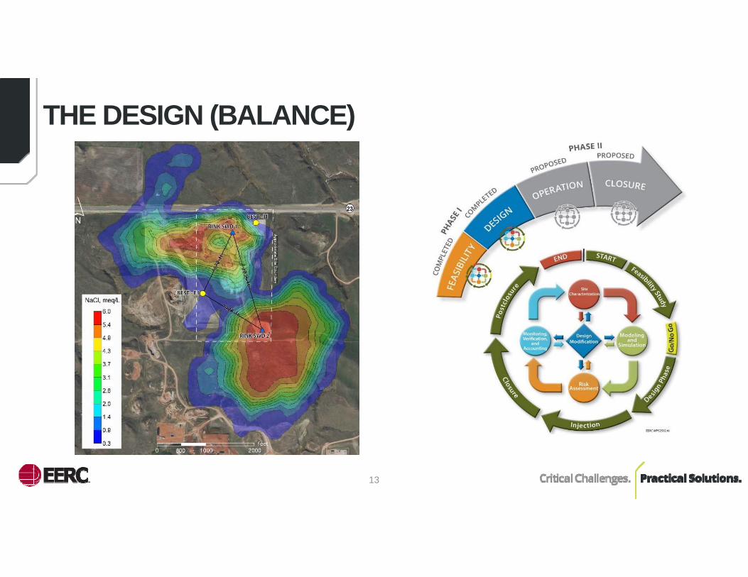
PHASE I

8
PHASE II GOALS AND OBJECTIVES
• Confirm efficacy of the ARM approaches developed during Phase I– Manage formation pressure– Predicting and monitoring plume movement– Validating pressure and brine plume model predictions
• Implement and operate a test bed facility for the evaluation of selected brine treatment technologies
• Three development stages over 48 months1. Site preparation and construction2. Site operations including ARM and extracted brine treatment technology testing
and demonstration3. Project closeout/decommissioning and data processing/reporting
9
THE WILLISTON BASIN
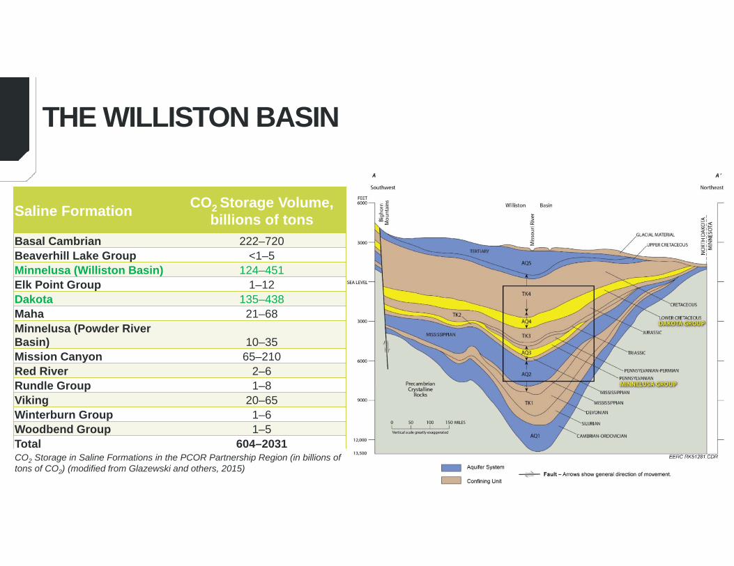
Saline Formation CO2 Storage Volume, billions of tons
Basal Cambrian 222–720Beaverhill Lake Group <1–5Minnelusa (Williston Basin) 124–451Elk Point Group 1–12Dakota 135–438Maha 21–68Minnelusa (Powder River Basin) 10–35Mission Canyon 65–210Red River 2–6Rundle Group 1–8Viking 20–65Winterburn Group 1–6Woodbend Group 1–5Total 604–2031CO2 Storage in Saline Formations in the PCOR Partnership Region (in billions oftons of CO2) (modified from Glazewski and others, 2015)

• Regional injection targets (CO2 and saltwater)
• Demonstrated capacity• Excellent proxy for CO2
injection into deep saline formations (DSFs)– Distributed well
network.– Open DSF system. – ARM will influence
multiple square miles of formation.
10
DAKOTA AND MINNELUSA GROUPS

• Develop ARM strategies• Validate performance against forecasts• ARM economics • Monitoring techniques • Brine treatment technology test bed• Demonstrate ARM implementation and
operations
11
FIELD IMPLEMENTATION PLAN (FIP)
12
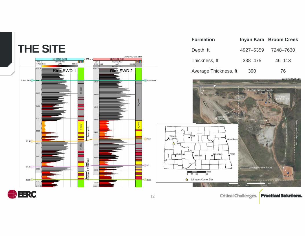
THE SITEFormation Inyan Kara Broom Creek
Depth, ft 4927–5359 7248–7630
Thickness, ft 338–475 46–113
Average Thickness, ft 390 76
13
THE DESIGN (BALANCE)
14
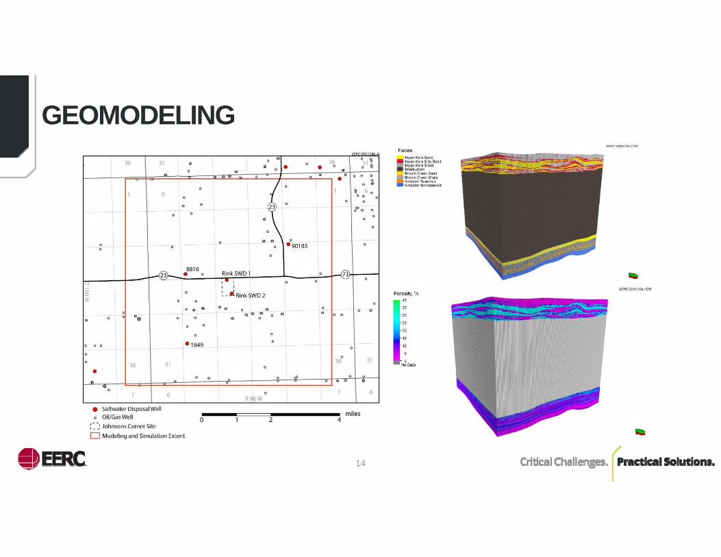
GEOMODELING
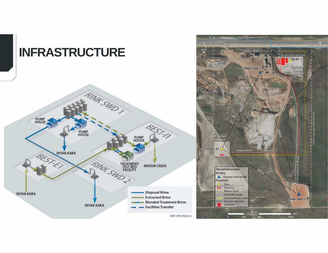
INFRASTRUCTURE
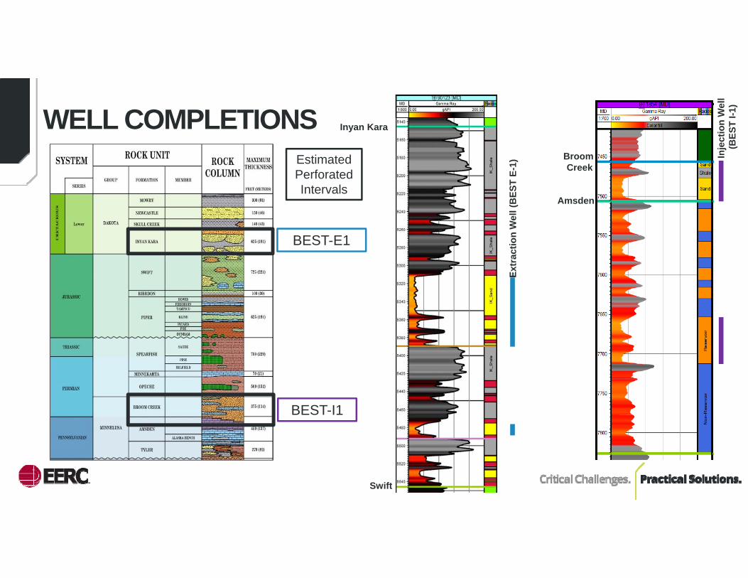
WELL COMPLETIONS
BEST-E1
BEST-I1
Estimated Perforated Intervals
Amsden
Broom Creek
Inyan Kara
Swift
Extr
actio
n W
ell (
BES
T E-
1)
Inje
ctio
n W
ell
(BES
T I-1
)

17
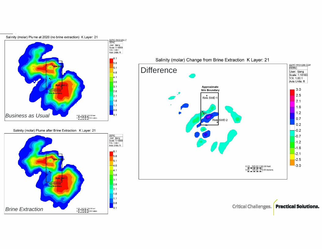
Difference
Business as Usual
Brine Extraction
18
Difference
Business as Usual
Brine Extraction
19
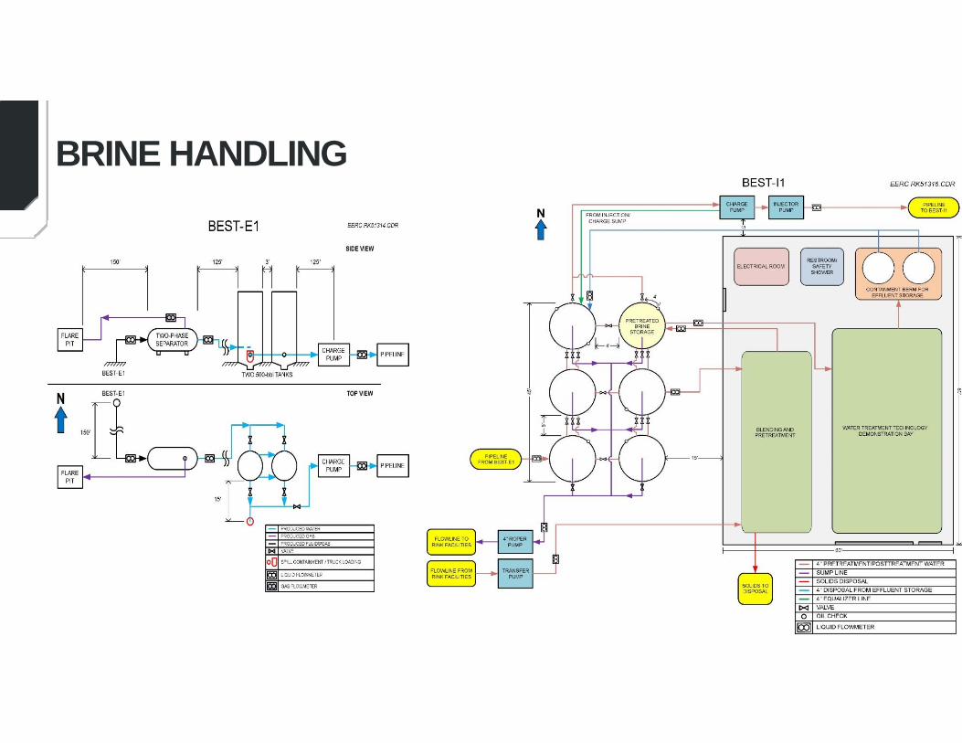
BRINE HANDLING
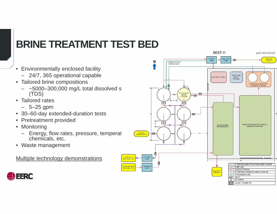
• Environmentally enclosed facility – 24/7, 365 operational capable
• Tailored brine compositions – ~5000–300,000 mg/L total dissolved solids
(TDS) • Tailored rates
– 5–25 gpm• 30–60-day extended-duration tests• Pretreatment provided• Monitoring
– Energy, flow rates, pressure, temperature, chemicals, etc.
• Waste management
Multiple technology demonstrations
20
BRINE TREATMENT TEST BED
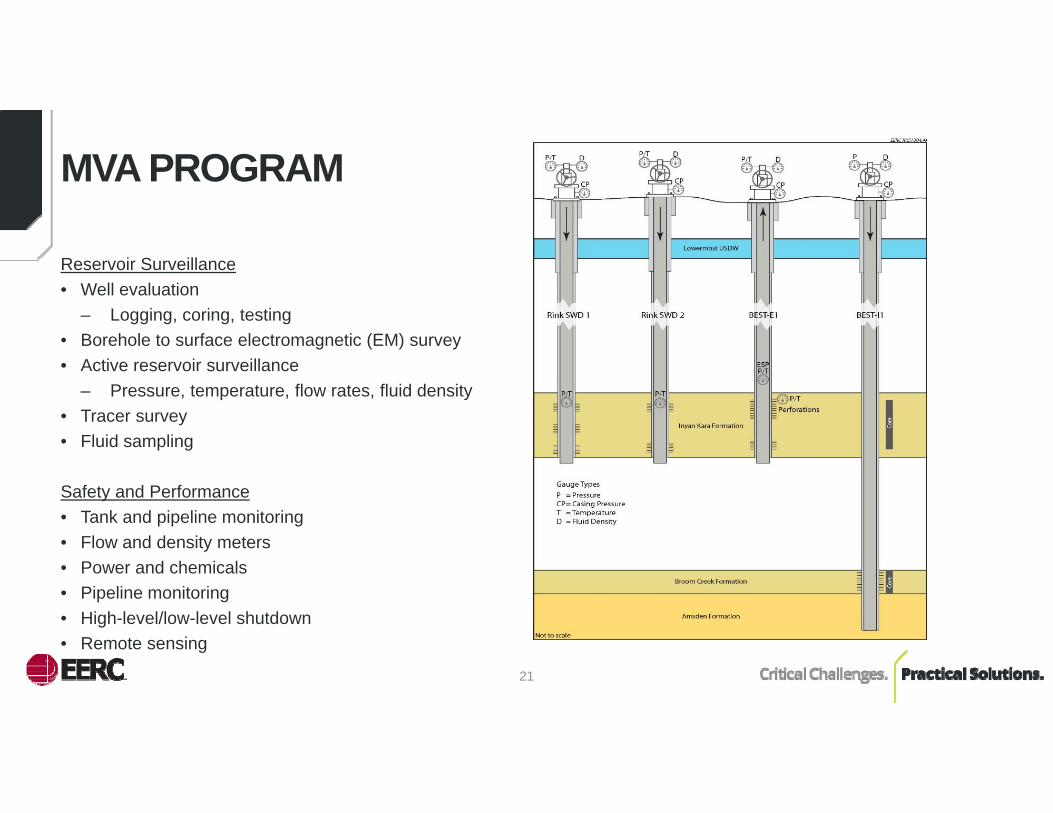
Reservoir Surveillance• Well evaluation
– Logging, coring, testing• Borehole to surface electromagnetic (EM) survey• Active reservoir surveillance
– Pressure, temperature, flow rates, fluid density• Tracer survey• Fluid sampling
Safety and Performance• Tank and pipeline monitoring• Flow and density meters• Power and chemicals• Pipeline monitoring • High-level/low-level shutdown• Remote sensing
21
MVA PROGRAM

• 58 potential risks– Technical– Resource availability– Health, safety, and environment (HSE)– Site access– Management
• Mitigation measures built into design and implementation plan
22
RISK ASSESSMENT
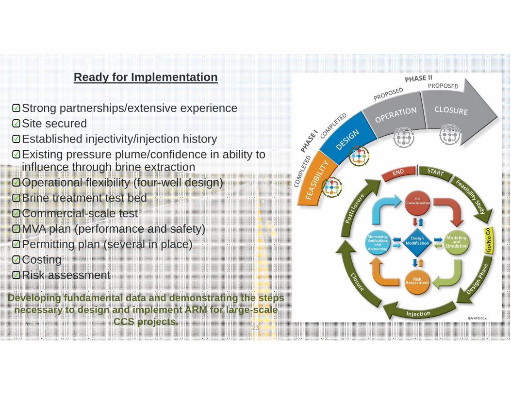
Ready for Implementation
Strong partnerships/extensive experienceSite securedEstablished injectivity/injection history Existing pressure plume/confidence in ability to influence through brine extractionOperational flexibility (four-well design)Brine treatment test bedCommercial-scale test MVA plan (performance and safety)Permitting plan (several in place)CostingRisk assessment
23
Developing fundamental data and demonstrating the steps necessary to design and implement ARM for large-scale
CCS projects.

Joint Knowledge Sharing Workshop with Sister BEST Project
24
SYNERGY OPPORTUNITIES
25
SUMMARY
• Benefit future CO₂ saline storage projects through development of engineering strategies which:– Reduce stress on sealing formations– Mechanism for controlling pressure and injected fluid plume– Reduce AOR
• Provide evidence for increased storage capacity and improved storage efficiency• Demonstrate a means of managing risk which will contribute to increased public and
regulatory acceptance• Best Practices
Energy & Environmental Research CenterUniversity of North Dakota15 North 23rd Street, Stop 9018Grand Forks, ND 58202-9018
www.undeerc.org701.777.5472 (phone)701.777.5181 (fax)
John A. Hamling, Principal [email protected]
26
CONTACT INFORMATION
THANK YOU!
29
PRESENTATION OUTLINE
• Introduction• Goals and Benefits• Project Overview & Implementation• Summary

30
APPENDIX
31
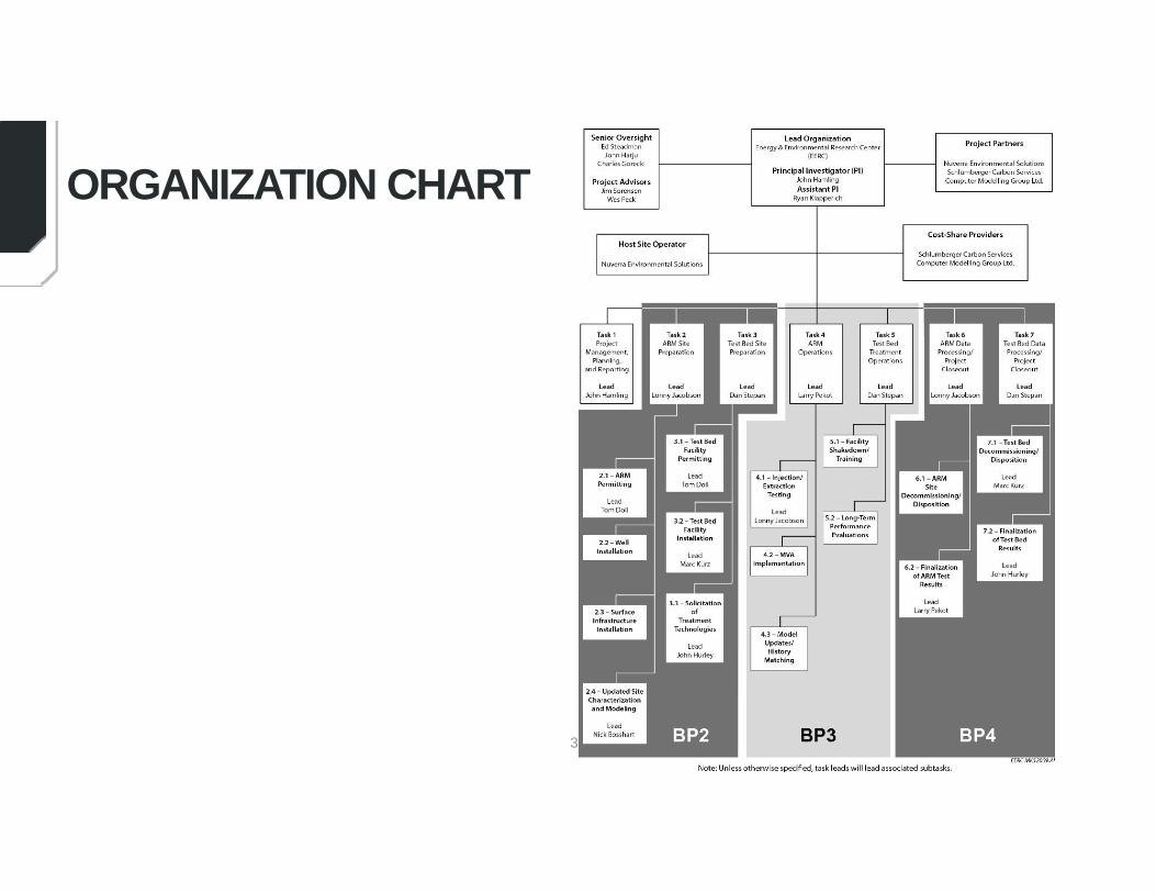
ORGANIZATION CHART
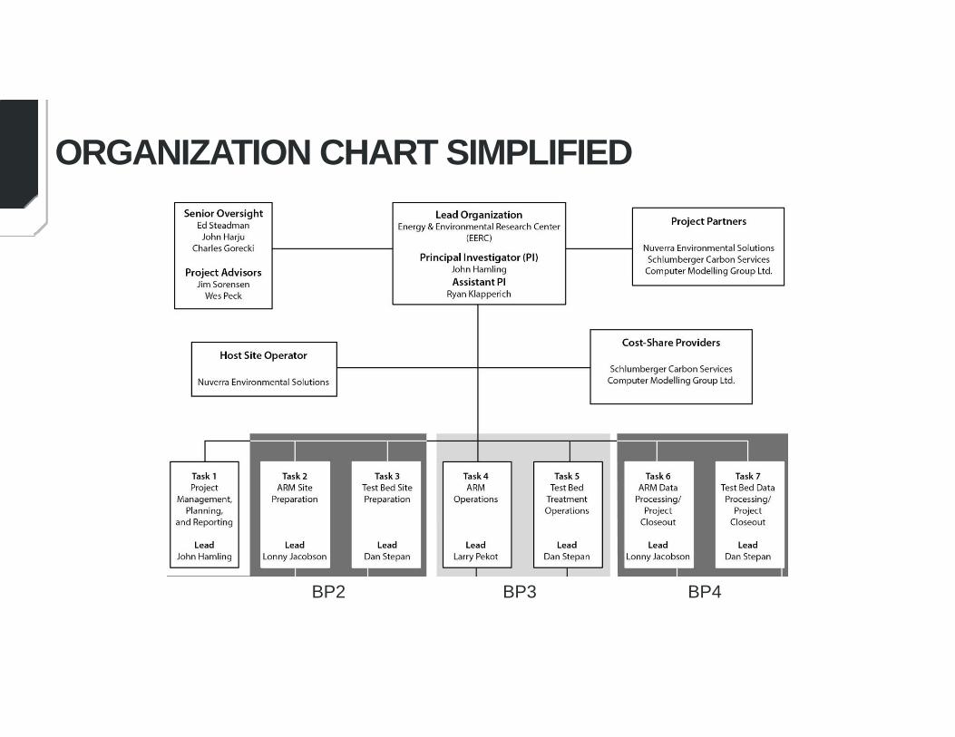
ORGANIZATION CHART SIMPLIFIED
BP2 BP3 BP4
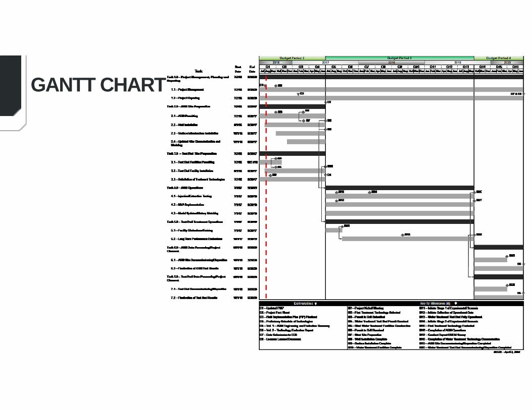
GANTT CHART
34
PRODUCTS
• Data and project-related information were uploaded to DOE’s Energy Data eXchange (EDX) site. The submission of these files corresponds to D3. Uploaded content included the following: – Carbon Capture, Utilization and Storage (CCUS) Conference abstract and
presentation– Phase I topical report– Porosity and permeability crossplot data for the Broom Creek, Amsden, and
Inyan Kara Formations – Anticipated Phase II well schematics for the injection and extraction wells– Image of the Williston Basin stratigraphy and hydrogeologic systems– Image of the Williston Basin formational cross section
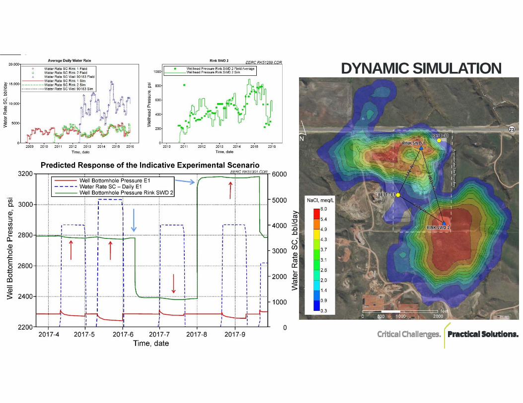
DYNAMIC SIMULATION