developing qualified ndt procedures & the technical ... filedeveloping qualified ndt procedures...
TRANSCRIPT

Developing Qualified NDT Procedures & The Technical Justification Process
iv
TABLE OF CONTENTS
Copyright Information ........................................................................................................................................ i Preface ................................................................................................................................................................... ii Acknowledgements ........................................................................................................................................... iii Table of Contents ............................................................................................................................................... iv Reading Guidelines ............................................................................................................................................. 1 Section 1 Developing an Inspection ................................................................................................................. 5 Chapter (1): Inspection Documentation (1) ....................................................................................................... 7
1.1 Introduction ....................................................................................................................................... 7 1.2 Standards ........................................................................................................................................... 7 1.3 Codes .................................................................................................................................................. 8 1.4 Specifications ..................................................................................................................................... 8 1.5 Written Instructions & Procedures ................................................................................................. 8 1.6 Reports ............................................................................................................................................... 9 1.7 Instruction Writing ......................................................................................................................... 10 1.8 What is Technical Writing? ........................................................................................................... 10 1.9 Inspection Development Overview ............................................................................................. 12 1.10 Requirements of a Procedure ........................................................................................................ 13 1.11 Procedure Development Process .................................................................................................. 13 1.12 Studies .............................................................................................................................................. 14 1.13 Technical Justification .................................................................................................................... 15
Chapter (2): Instruction & Procedure Writing (1) (2) ........................................................................................ 17 2.1 Contents of a Written Instruction ................................................................................................. 17 2.2 Contents of a Procedure ................................................................................................................. 17 2.3 Introduction ..................................................................................................................................... 18 2.4 Scope ................................................................................................................................................. 18 2.5 Purpose ............................................................................................................................................ 18 2.6 Definitions/Acronyms .................................................................................................................... 18 2.7 Inspection Requirements ............................................................................................................... 19 2.8 References & Standards ................................................................................................................. 19 2.9 Personnel Qualifications & Duties ............................................................................................... 19 2.10 Safety Requirements ....................................................................................................................... 19 2.11 Test Part Description ...................................................................................................................... 19 2.12 Preparation Prior to Inspection ..................................................................................................... 20 2.13 List of Equipment & Accessories .................................................................................................. 20 2.14 Equipment Calibration ................................................................................................................... 22 2.15 Examination Technique ................................................................................................................. 22 2.16 Recording Criteria .......................................................................................................................... 23 2.17 Acceptance Criteria ........................................................................................................................ 23
Developing Qualified NDT Procedures & The Technical Justification Process
v
2.18 Disposition Instructions ................................................................................................................. 23 2.19 Reporting Criteria ........................................................................................................................... 23 2.20 References ........................................................................................................................................ 24 2.21 Approvals ........................................................................................................................................ 24 2.22 Appendixes ...................................................................................................................................... 24
Chapter (3): Technical Developments ............................................................................................................ 25 3.1 Introduction ..................................................................................................................................... 25 3.2 The Scientific Method ..................................................................................................................... 27 3.3 The Engineering Design Process .................................................................................................. 28 3.4 Feasibility Study Process ............................................................................................................... 29 3.5 Technique(s) .................................................................................................................................... 30 3.6 Technical Justification .................................................................................................................... 31 3.7 Qualification .................................................................................................................................... 32
Chapter (4): Qualification(s) ............................................................................................................................ 33 4.1 Procedure Qualification ................................................................................................................. 33 4.2 Equipment Qualification ............................................................................................................... 33 4.3 Personnel Qualification .................................................................................................................. 34 4.4 Qualification Documentation ........................................................................................................ 35 4.5 The Qualification Process .............................................................................................................. 37
Chapter (5): Technical Justifications .............................................................................................................. 41 5.1 Contents of a Technical Justification ............................................................................................ 41 5.2 Summary of Relevant Input Information .................................................................................... 42 5.3 Overview of the Inspection System .............................................................................................. 43 5.4 Analysis of the Influential Parameters ......................................................................................... 44 5.5 Review of Personnel Requirements ............................................................................................. 44 5.6 Physical Reasoning ......................................................................................................................... 44 5.7 Prediction by Modelling ................................................................................................................ 45 5.8 Experimental Method & Evidence ............................................................................................... 45 5.9 Statistical Analysis .......................................................................................................................... 46 5.10 Parametric Studies .......................................................................................................................... 47 5.11 Equipment & Data Analysis Considerations .............................................................................. 47 5.12 Review of all Presented Evidence ................................................................................................. 47 5.13 Input on Test Pieces for Practical Trials ....................................................................................... 47 5.14 Conclusion ....................................................................................................................................... 47 5.15 References ........................................................................................................................................ 48
Chapter (6): EM TJ Inspection Parameters .................................................................................................... 49 6.1 List of Parameters ........................................................................................................................... 49 6.2 Component ...................................................................................................................................... 49 6.3 Defects .............................................................................................................................................. 51 6.4 Procedure Parameters .................................................................................................................... 52 6.5 Equipment Parameters ................................................................................................................... 54
Chapter (7): Ultrasonic TJ Inspection Parameters ........................................................................................ 57
Developing Qualified NDT Procedures & The Technical Justification Process
vi
7.1 Component ...................................................................................................................................... 57 7.2 Defects .............................................................................................................................................. 58 7.3 Procedure Parameters .................................................................................................................... 59 7.4 Equipment Parameters ................................................................................................................... 61 7.5 Probe(s) ............................................................................................................................................ 63 7.6 Scanner ............................................................................................................................................. 63 7.7 Example Parameters as Defined by ASME V Article 4 .............................................................. 64
Chapter (8): TJ Writing Guidelines................................................................................................................. 69 8.1 Purpose of the TJ Document ......................................................................................................... 70 8.2 Qualification & the TJ Document ................................................................................................. 70 8.3 Where to Begin ................................................................................................................................ 73 8.4 The Final Document ....................................................................................................................... 74
Chapter (9): Introduction to TJ Studies .......................................................................................................... 75 9.1 Introduction ..................................................................................................................................... 75 9.2 Calibration ....................................................................................................................................... 75 9.3 Signal Variance................................................................................................................................ 78 9.4 Noise Study & the SNR .................................................................................................................. 81 9.5 Signal Coverage .............................................................................................................................. 81 9.6 Probability of Detection ................................................................................................................. 81 9.7 Probability of False Call ................................................................................................................. 82 9.8 Acquisition Rate(s) ......................................................................................................................... 82 9.9 Parametric Studies .......................................................................................................................... 83
Chapter (10): Calibration Curves ..................................................................................................................... 85 10.1 What is a calibration curve? .......................................................................................................... 85 10.2 The Method of Least Squares ........................................................................................................ 85 10.3 Limitations & Cautions .................................................................................................................. 88 10.4 ET/ECAT Calibration Curves ........................................................................................................ 88 10.5 Ultrasonic Calibration Curves ...................................................................................................... 90 10.6 Variance Compensated TVG Curves ........................................................................................... 92
Chapter (11): Noise Study ................................................................................................................................. 95 11.1 What is a Noise Study? .................................................................................................................. 95 11.2 What is Noise? ................................................................................................................................. 95 11.3 What is the Signal Response? ........................................................................................................ 96 11.4 What is the Signal to Noise Ratio? (1) ............................................................................................ 96 11.5 Improving the Signal to Noise ratio ............................................................................................. 97 11.6 Common Noise Distributions ....................................................................................................... 97 11.7 Guidance for Performing a Noise Study ................................................................................... 100 11.8 Selection of the Noise Distribution ............................................................................................. 100
Chapter (12): Sizing Accuracy Study ............................................................................................................ 103 12.1 NDT Measurements ..................................................................................................................... 103 12.2 What is a sizing accuracy study? ................................................................................................ 103 12.3 Background Sizing Accuracy Mathematics............................................................................... 104
Developing Qualified NDT Procedures & The Technical Justification Process
vii
12.4 Sizing Accuracy Regression Plot ................................................................................................ 106 12.5 Sizing Accuracy Scatter Plot ........................................................................................................ 107 12.6 Calibration Curves With Maximum Accuracy ......................................................................... 108
Section 1 Summary .......................................................................................................................................... 111 Introduction .............................................................................................................................................. 111 Chapter Summaries ................................................................................................................................. 111 Connecting Concepts ............................................................................................................................... 113
Section 2 Probability of Detection & Inspection Qualification .............................................................. 115 Chapter (13): Historical Development of NDT Reliability Techniques ................................................ 117
13.1 Introduction ................................................................................................................................... 117 13.2 Derivation of PoD Curves ........................................................................................................... 118 13.3 Requirements & Experimentation .............................................................................................. 121 13.4 Modelling PoD .............................................................................................................................. 121
Chapter (14): Probability of Detection ......................................................................................................... 123 14.1 What is a POD study? .................................................................................................................. 123 14.2 Definitions ..................................................................................................................................... 124 14.3 Introduction to POD Models ....................................................................................................... 125 14.4 PoD Model Guidance ................................................................................................................... 127 14.5 POD Model Fit .............................................................................................................................. 130 14.6 â vs. a PoD Model ......................................................................................................................... 131 14.7 Generalized Linear Models (GLMs) ........................................................................................... 137 14.8 MLE PoD Model Convergence ................................................................................................... 144 14.9 The Nordtest Technique .............................................................................................................. 146 14.10 PoD Model Regression Plots ....................................................................................................... 146
Chapter (15): PoD Model Confidence Levels .............................................................................................. 149 15.1 Introduction ................................................................................................................................... 149 15.2 Wald Confidence Method............................................................................................................ 149 15.3 Wilson-Score Method ................................................................................................................... 150 15.4 Exact Clopper-Pearson Method .................................................................................................. 151 15.5 The ChenG and Iles Confidence Method .................................................................................. 151 15.6 Wald Confidence Method Sample Size ..................................................................................... 154 15.7 Confidence Interval Method Selection ....................................................................................... 156
Chapter (16): PoD Model Optimization ....................................................................................................... 157 16.1 Threshold Optimization............................................................................................................... 157 16.2 Nordtest Binning Optimization .................................................................................................. 160 16.3 Probability of False Call ............................................................................................................... 163
Chapter (17): Advanced PoD models ............................................................................................................ 165 17.1 Introduction to Advanced PoD Models .................................................................................... 165 17.2 Floor Ceiling Models (150+pts) ................................................................................................... 165 17.3 Noise Interference Models ........................................................................................................... 168 17.4 Robust PoD Statistics .................................................................................................................... 169 17.5 Iteration Weighted Regression .................................................................................................... 170
Developing Qualified NDT Procedures & The Technical Justification Process
viii
17.6 Non-Linear Regression ................................................................................................................ 172 17.7 Distribution Model Fit PoD (DMFPoD) ..................................................................................... 172 17.8 Advanced PoD Methods .............................................................................................................. 173
Chapter (18): Transform Functions ............................................................................................................... 175 18.1 Transfer Value ............................................................................................................................... 175 18.2 Transform Function ...................................................................................................................... 176 18.3 Transform Function Example ..................................................................................................... 177
Chapter (19): MAPoD ...................................................................................................................................... 181 19.1 Why Use Model Assistance? ....................................................................................................... 181 19.2 Model Assistance Methodology ................................................................................................. 181 19.3 Statistical Built MAPoD ............................................................................................................... 182 19.4 Mathematical MAPoD (FEMA) .................................................................................................. 184 19.5 Advantages and Limitations ....................................................................................................... 186 19.6 Example MAPoD .......................................................................................................................... 186
Chapter (20): Evaluating a PoD Value .......................................................................................................... 189 20.1 Graphing a PoD Function ............................................................................................................ 189 20.2 Solving size given a PoD Value .................................................................................................. 190 20.3 Comparison of PoD Models ........................................................................................................ 191
Chapter (21): Demonstrating Inspection System Capabilities ................................................................ 193 21.1 Introduction ................................................................................................................................... 193 21.2 The Point Evaluation Process ...................................................................................................... 193 21.3 System Qualification Details ....................................................................................................... 194 21.4 Determination of the Upper and Lower Confidence Limits on a given Proportion ........... 195 21.5 Example Point Evaluation Qualification Report Form ............................................................ 196 21.6 Alternative Sample Options ........................................................................................................ 198 21.7 PoD Model Effects using Measured Size Instead of True Size ............................................... 199
Section 2 Summary .......................................................................................................................................... 203 Introduction .............................................................................................................................................. 203 Chapter Summaries ................................................................................................................................. 203 Connecting Concepts ............................................................................................................................... 205
Section 3 Introduction to NDT Study Methodology & Analysis ............................................................ 207 Chapter (22): Introduction To NDT Experiments ...................................................................................... 209
22.1 Data ................................................................................................................................................. 209 22.2 Statistical Analysis ........................................................................................................................ 211 22.3 Theoretical Analysis ..................................................................................................................... 212
Chapter (23): Experiments .............................................................................................................................. 213 23.1 Introduction ................................................................................................................................... 214 23.2 Definitions & Abbreviations ....................................................................................................... 214 23.3 Assumptions & Restrictions ........................................................................................................ 215 23.4 Personnel ........................................................................................................................................ 215 23.5 Details of Proposed Test .............................................................................................................. 215 23.6 The Test Hypothesis ..................................................................................................................... 215
Developing Qualified NDT Procedures & The Technical Justification Process
ix
23.7 Details of the Test Samples .......................................................................................................... 216 23.8 Overview of the Equipment ........................................................................................................ 216 23.9 Summary of the Output Response ............................................................................................. 217 23.10 The Input Factors .......................................................................................................................... 217 23.11 Experiment Design and Sample Size ......................................................................................... 218 23.12 Experimental Data ........................................................................................................................ 218 23.13 Data Analysis ................................................................................................................................ 219 23.14 Summary & Conclusions ............................................................................................................. 220 23.15 Recommendations ........................................................................................................................ 221 23.16 References ...................................................................................................................................... 221 23.17 Appendixes .................................................................................................................................... 221
Chapter (24): Introduction to Design of Experiments (DoE) .................................................................... 223 24.1 The terminology ............................................................................................................................ 223 24.2 Design of Experiments (DOE) ..................................................................................................... 225 24.3 Types of Experiments ................................................................................................................... 227 24.4 Factorial Experiments................................................................................................................... 229 24.5 Experimental Control Methods .................................................................................................. 230 24.6 Example Study Designs ............................................................................................................... 231 24.7 Designing an Experiment ............................................................................................................ 233
Chapter (25): Feasibility Studies & Developments.................................................................................... 235 25.1 Introduction ................................................................................................................................... 235 25.2 Types of Feasibility Studies ......................................................................................................... 235 25.3 Demonstration or Test.................................................................................................................. 236 25.4 Repeatable Test ............................................................................................................................. 237 25.5 Investigation .................................................................................................................................. 237 25.6 Solution .......................................................................................................................................... 238 25.7 Repeatable & Justified Solution .................................................................................................. 238 25.8 Example Study Design ................................................................................................................. 245 25.9 Study Progression ......................................................................................................................... 247 25.10 Study Analysis Tools .................................................................................................................... 248
Chapter (26): Introduction to Hypothesis Testing ..................................................................................... 249 26.1 Introduction ................................................................................................................................... 249 26.2 Steps in Hypothesis Testing ........................................................................................................ 249 26.3 Regions of for Rejection & Acceptance ...................................................................................... 250 26.4 Hypothesis Tests ........................................................................................................................... 252 26.5 The P-Value Approach ................................................................................................................. 252 26.6 Testing 2 Groups ........................................................................................................................... 253 26.7 NDT Hypothesis Test Examples ................................................................................................. 255
Chapter (27): ANOVA ..................................................................................................................................... 257 27.1 Single Factor ANOVA .................................................................................................................. 258 27.2 Factorial Experiment ANOVA .................................................................................................... 262 27.3 One-way ANOVA Example ........................................................................................................ 263
Developing Qualified NDT Procedures & The Technical Justification Process
x
Chapter (28): MANOVA ................................................................................................................................. 265 Section 3 Summary .......................................................................................................................................... 273
Introduction .............................................................................................................................................. 273 Chapter Summaries ................................................................................................................................. 273 Connecting Concepts ............................................................................................................................... 274
Section 4 ET & ECAT Example Studies ....................................................................................................... 275 Chapter (29): ECT Noise Study Example ..................................................................................................... 277
29.1 Test Sample .................................................................................................................................... 277 29.2 Test Equipment ............................................................................................................................. 277 29.3 Data Acquisition ........................................................................................................................... 278 29.4 Data Analysis ................................................................................................................................ 278 29.5 Normal Distribution Statistical Evaluation ............................................................................... 279 29.6 Noise Model Selection .................................................................................................................. 280 29.7 Experiment Design Guidelines ................................................................................................... 284
Chapter (30): ECAT Sizing Accuracy Study Example ............................................................................... 285 30.1 Measurement Accuracy Being Tested ........................................................................................ 285 30.2 Example Sizing Accuracy Study ................................................................................................. 287 30.3 Test Sample .................................................................................................................................... 287 30.4 Test Equipment ............................................................................................................................. 288 30.5 Data Acquisition ........................................................................................................................... 288 30.6 Data Analysis ................................................................................................................................ 289 30.7 Statistical Evaluation .................................................................................................................... 290 30.8 Experiment Design Guidelines ................................................................................................... 293
Chapter (31): ECAT Coverage Study Example ............................................................................................ 295 31.1 What is a Coverage Study? .......................................................................................................... 295 31.2 Test Sample .................................................................................................................................... 296 31.3 Inspection Equipment .................................................................................................................. 296 31.4 Data Acquisition ........................................................................................................................... 297 31.5 Data Analysis ................................................................................................................................ 297 31.6 Results and Conclusions .............................................................................................................. 300 31.7 Experiment Design Guidelines ................................................................................................... 300
Chapter (32): ECAT 𝒂 𝒗𝒔.𝒂 PoD Study Example ........................................................................................ 301 32.1 Test Samples .................................................................................................................................. 301 32.2 Test Instruments ........................................................................................................................... 301 32.3 Test Probe ...................................................................................................................................... 302 32.4 Calibration Plates .......................................................................................................................... 302 32.5 Scanning Fixture ........................................................................................................................... 303 32.6 Other Equipment .......................................................................................................................... 303 32.7 Data Acquisition ........................................................................................................................... 303 32.8 Data Analysis ................................................................................................................................ 303 32.9 Statistical Evaluation .................................................................................................................... 304 32.10 Summary & Recomendations ..................................................................................................... 305
Developing Qualified NDT Procedures & The Technical Justification Process
xi
32.11 Experiment Design Guidelines ................................................................................................... 306 Chapter (33): ECAT PoFC Example ............................................................................................................... 307
33.1 Test Sample & Equipment ........................................................................................................... 307 33.2 Noise Model Analysis .................................................................................................................. 307 33.3 Statistical Evaluation .................................................................................................................... 308 33.4 Results and Conclusions .............................................................................................................. 308
Chapter (34): ECT & ECA Modelling Examples ......................................................................................... 309 34.1 Introduction ................................................................................................................................... 309 34.2 TEDDY ........................................................................................................................................... 309 34.3 CIVA ............................................................................................................................................... 310 34.4 Real Data Models .......................................................................................................................... 311
Section 4 Summary .......................................................................................................................................... 313 Introduction .............................................................................................................................................. 313 Chapter Summaries ................................................................................................................................. 313
Section 5 UT & PAUT Example Studies ...................................................................................................... 315 Chapter (35): PAUT Attenuation, DAC & TVG/TCG Example ............................................................... 317
35.1 Test Sample & Inspection Requirements ................................................................................... 317 35.2 Test Equipment ............................................................................................................................. 317 35.3 Data Acquisition ........................................................................................................................... 318 35.4 Data Analysis ................................................................................................................................ 318 35.5 Statistical Evaluation .................................................................................................................... 318 35.6 Summary & Recommendations .................................................................................................. 325 35.7 Experiment Design Guidelines ................................................................................................... 326
Chapter (36): PAUT Noise Study Example .................................................................................................. 327 36.1 Test Sample .................................................................................................................................... 327 36.2 Test Equipment ............................................................................................................................. 327 36.3 Data Acquisition ........................................................................................................................... 328 36.4 Data Analysis ................................................................................................................................ 328 36.5 The Data ......................................................................................................................................... 328 36.6 Statistical Evaluation .................................................................................................................... 329 36.7 Summary & Recommendations .................................................................................................. 330 36.8 Experiment Design Guidelines ................................................................................................... 330
Chapter (37): PAUT Sizing Accuracy Study Example ............................................................................... 333 37.1 Test Sample .................................................................................................................................... 333 37.2 Test Equipment ............................................................................................................................. 333 37.3 Data Acquisition ........................................................................................................................... 334 37.4 Data Analysis ................................................................................................................................ 334 37.5 Statistical Evaluation .................................................................................................................... 334 37.6 Experiment Design Guidelines (18) .............................................................................................. 337
Chapter (38): PAUT Hit/Miss PoD Study Example .................................................................................... 339 38.1 Study Requirements ..................................................................................................................... 339 38.2 Test Sample .................................................................................................................................... 339
Developing Qualified NDT Procedures & The Technical Justification Process
xii
38.3 Data Acquisition ........................................................................................................................... 339 38.4 Noise Analysis and the PoFC ...................................................................................................... 340 38.5 Data Analysis of the Initial Technique ....................................................................................... 343 38.6 Technique Optimization .............................................................................................................. 344 38.7 Data Analysis of the Optimized Technique .............................................................................. 345 38.8 Summary & Recommendations .................................................................................................. 346 38.9 Experiment Design Guidelines ................................................................................................... 346
Chapter (39): PAUT Modelling Example ..................................................................................................... 347 39.1 Introduction ................................................................................................................................... 347 39.2 Setting up the Models .................................................................................................................. 347 39.3 Example Models ........................................................................................................................... 348 39.4 Model Analysis ............................................................................................................................. 350 39.5 Summary & Recommendations .................................................................................................. 352
Section 5 Summary .......................................................................................................................................... 353 Introduction .............................................................................................................................................. 353 Chapter Summaries ................................................................................................................................. 353
Appendix A: List of Common Acronyms .................................................................................................... 355 Appendix B: Statistical Functions ................................................................................................................. 359
Mathematical Notations .......................................................................................................................... 359 Descriptive Statistics Definitions & Relations ...................................................................................... 361 Probability Distributions ......................................................................................................................... 362 Linear Regression ..................................................................................................................................... 364 Linear Regression Error & Confidence ................................................................................................. 364
Appendix C: â vs. a PoD Model Mathematics ............................................................................................ 365 Appendix D: Logit PoD Model Mathematics (9) .......................................................................................... 377 Appendix E: Probit PoD Model Mathematics (9) ......................................................................................... 381 Appendix F: LogLog PoD Model Mathematics (9) ...................................................................................... 385 Appendix G: cLogLog PoD Model Mathematics (9) .................................................................................... 389 Appendix H: Logit Floor Ceiling PoD Model Mathematics (9) ................................................................. 393
The Summary:........................................................................................................................................... 393 The Solution: ............................................................................................................................................. 394
Appendix I: â vs. a Floor Ceiling Model PoD Model Mathematics Summary (10) ................................. 405 Appendix J: Glossary ....................................................................................................................................... 407 List of Figures ................................................................................................................................................... 414 List of Tables ..................................................................................................................................................... 419 Works Cited ...................................................................................................................................................... 421 Index ................................................................................................................................................................... 423
Chapter (4): Qualification(s)
33
CHAPTER (4): QUALIFICATION(S)
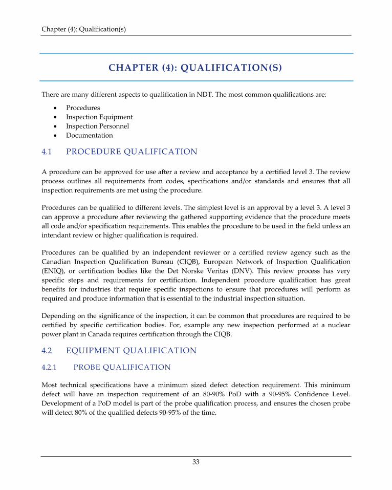
There are many different aspects to qualification in NDT. The most common qualifications are:
• Procedures • Inspection Equipment • Inspection Personnel • Documentation
4.1 PROCEDURE QUALIFICATION
A procedure can be approved for use after a review and acceptance by a certified level 3. The review process outlines all requirements from codes, specifications and/or standards and ensures that all inspection requirements are met using the procedure.
Procedures can be qualified to different levels. The simplest level is an approval by a level 3. A level 3 can approve a procedure after reviewing the gathered supporting evidence that the procedure meets all code and/or specification requirements. This enables the procedure to be used in the field unless an intendant review or higher qualification is required.
Procedures can be qualified by an independent reviewer or a certified review agency such as the Canadian Inspection Qualification Bureau (CIQB), European Network of Inspection Qualification (ENIQ), or certification bodies like the Det Norske Veritas (DNV). This review process has very specific steps and requirements for certification. Independent procedure qualification has great benefits for industries that require specific inspections to ensure that procedures will perform as required and produce information that is essential to the industrial inspection situation.
Depending on the significance of the inspection, it can be common that procedures are required to be certified by specific certification bodies. For, example any new inspection performed at a nuclear power plant in Canada requires certification through the CIQB.
4.2 EQUIPMENT QUALIFICATION
4.2.1 PROBE QUALIFICATION
Most technical specifications have a minimum sized defect detection requirement. This minimum defect will have an inspection requirement of an 80-90% PoD with a 90-95% Confidence Level. Development of a PoD model is part of the probe qualification process, and ensures the chosen probe will detect 80% of the qualified defects 90-95% of the time.
Chapter (4): Qualification(s)
34
The development of a PoD model can be a fairly involved process. A proper PoD study involves several minor models. The PoD calculations are dependent upon a noise response model.
The following are the most common statistical models that are built for a PoD study:
• Noise Studies • PoD Model • Binary Regression Models – Hit Miss Data • â vs. a Model – Amplitude Response • Minimum calling threshold • Probability of a False Call
A proper PoD model must take several factors into consideration during development. The average lift-off, average noise response, and the variation from the coverage or the coil position must also be factored into the PoD model. A full PoD study is essential when trying to evaluate the minimum capabilities of the inspection system.
PoD models are discussed in detail in Section 2.
Common technical justification studies are discussed in Chapter (9):.
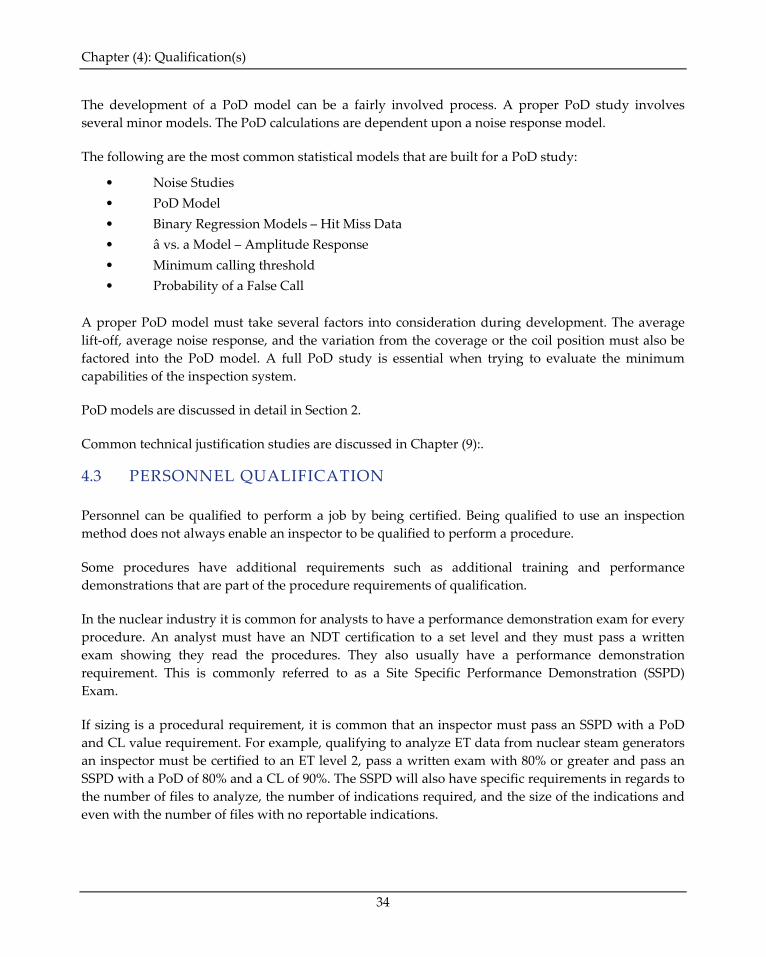
4.3 PERSONNEL QUALIFICATION
Personnel can be qualified to perform a job by being certified. Being qualified to use an inspection method does not always enable an inspector to be qualified to perform a procedure.
Some procedures have additional requirements such as additional training and performance demonstrations that are part of the procedure requirements of qualification.
In the nuclear industry it is common for analysts to have a performance demonstration exam for every procedure. An analyst must have an NDT certification to a set level and they must pass a written exam showing they read the procedures. They also usually have a performance demonstration requirement. This is commonly referred to as a Site Specific Performance Demonstration (SSPD) Exam.
If sizing is a procedural requirement, it is common that an inspector must pass an SSPD with a PoD and CL value requirement. For example, qualifying to analyze ET data from nuclear steam generators an inspector must be certified to an ET level 2, pass a written exam with 80% or greater and pass an SSPD with a PoD of 80% and a CL of 90%. The SSPD will also have specific requirements in regards to the number of files to analyze, the number of indications required, and the size of the indications and even with the number of files with no reportable indications.

Chapter (4): Qualification(s)
35
4.4 QUALIFICATION DOCUMENTATION
There are several different types of qualification documents. The most common are the technical justification, certification documentation and a training plan.
4.4.1 TRAINING PLAN
Training plans are commonly required as part of a technical justification requirement.
A TJ will reference the training plan when discussing how someone becomes qualified to perform the inspection.
The recommended contents of a training plan should contain the following as a minimum:
• Purpose • List of Acronyms • Training Requirements • Prerequisites • References
• Scope • Organization • Performance Testing For Qualification • Documentation • Appendixes
Purpose - The procedures that the training plan is covering should be outlined in this section.
Scope – This section should include details describing what positions are being covered in the training plan. For example, DAQ, DAN, Supervisor roles, etc.
List of Acronyms – All acronyms used throughout the training plan document should be addressed in this section. Uncommon terms or terms that require definition should also be addressed in this section to help reduce any ambiguity when reading the document.
Organization – this section discusses what equipment is required to perform the training and who is qualified to give the training. The certification & experience required for someone to become a trainer is outlined in this section. Specific candidates’ qualifications are discussed with regards to each role in the inspection. NDE shift supervisors, DAQ inspectors & NDE DAN inspectors will have specific certification and experience requirements before being acceptable to train for the inspection.
Training Requirements – A general overview of the training program is discussed as an introduction for this section. A detailed overview of the specific training for each personnel’s role (DAQ, DAN, etc.) in the procedure is discussed. All training topics should be outlined in this section. Details about performing calibrations, data acquisition and analysis are also contained in this section.
Performance Testing For Qualification – This section discusses the testing responsibility. Once a candidate is qualified they become responsible when performing all tasks in the procedure. The

Chapter (4): Qualification(s)
36
specific details required to demonstrate a candidate’s qualification are outlined in this section. Details covering the written test and the practical examination protocol for each role in the inspection is fully outlined.
Also, the final assessment (marking or pass/fail criteria) is discussed in this section.
Prerequisites – This section outlines all the prerequisites all candidates require before being eligible for qualification to perform any role in the procedure.
Documentation – All training must be documented. The training documentation requires the use of several forms. Each form should be discussed in detail.
References – All procedures required to successfully perform the specific procedure(s) that the training plan is training personnel to should be included in the reference section and available during the training of all personnel.
Appendixes should contain the following:
• Details of all Training & Performance Test Samples • Training Activity Sign-In Roster • NDT Shift Supervisor Performance Evaluation Record • DAQ Performance Evaluation Record • DAN for Reporting Performance Evaluation Record
4.4.2 TECHNICAL JUSTIFICATION
The technical justification document outlines the evidence that a procedure meets code or engineering requirements for the inspection.
Technical justification documents are discussed in detail in Chapter (5):.
4.4.3 CERTIFICATION
All NDE certifications qualify personnel to be eligible to perform duties of a procedure. NDE Certified personnel have demonstrated a level of competency in the specific NDE method. An NDE certification does not qualify someone to perform a qualified procedure. Most qualified procedures require both NDE certification and specific procedure training to be qualified to perform the procedure. Specific training requirements are discussed in section 4.4.1.
Each level of NDE certification will have duties that they are qualified to perform.
Traditionally, level 1 certified personnel are qualified to acquire data and most procedures require all level 1 personnel to work under direct supervision of a level 2 or higher.
Chapter (4): Qualification(s)
37
Most procedures require NDE personnel to be qualified to ISO 9712:2012 or equivalent.
When required, the national or international certification may be augmented or replaced by qualification and certification to a Standard Practice following the guidelines of SNT-TC-1A-2011.
SNT-TC-1A certified personnel shall be certified to the requirements of an internal SNT-TC-1A written practice. The requirements of the written practice are very detailed, and companies require many documents to be compliant with this certification scheme. Note: Certain codes or standards may require the use of additional or alternate certification schemes.
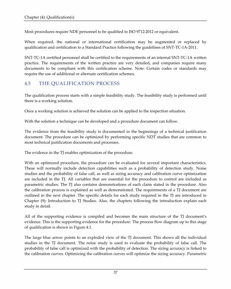
4.5 THE QUALIFICATION PROCESS
The qualification process starts with a simple feasibility study. The feasibility study is performed until there is a working solution.
Once a working solution is achieved the solution can be applied to the inspection situation.
With the solution a technique can be developed and a procedure document can follow.
The evidence from the feasibility study is documented in the beginnings of a technical justification document. The procedure can be optimized by performing specific NDT studies that are common to most technical justification documents and processes.
The evidence in the TJ enables optimization of the procedure.
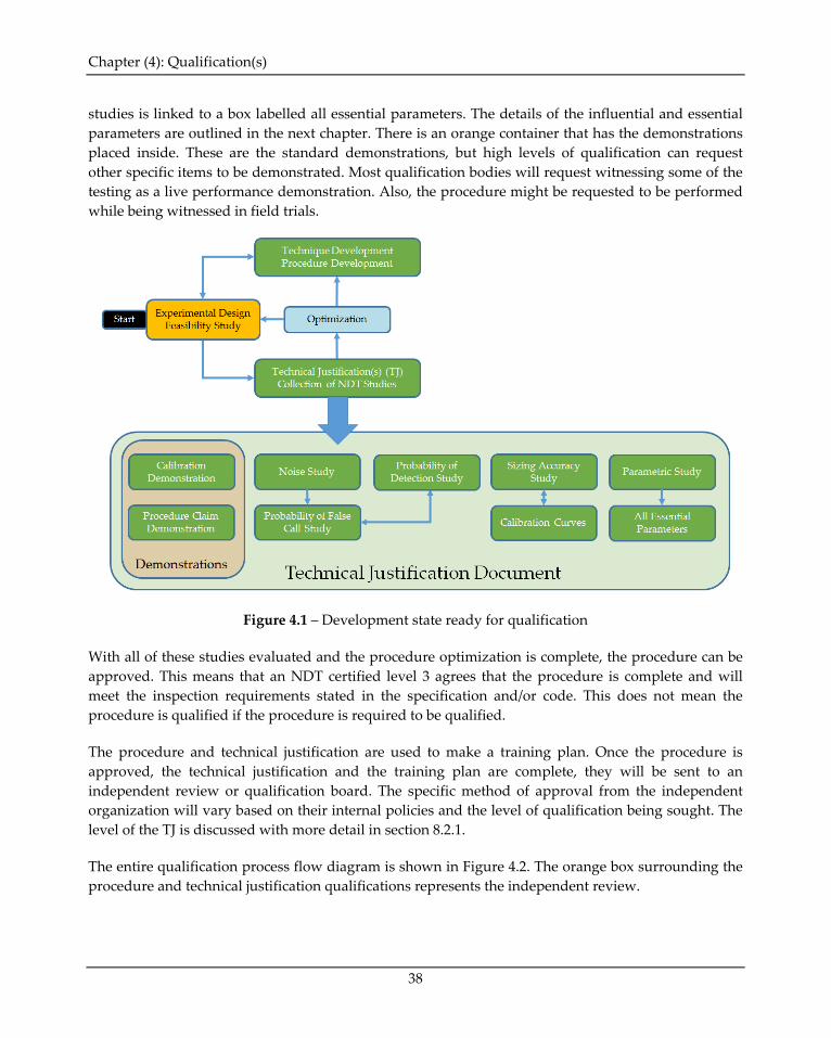
With an optimized procedure, the procedure can be evaluated for several important characteristics. These will normally include detection capabilities such as a probability of detection study. Noise studies and the probability of false call, as well as sizing accuracy and calibration curve optimization are included in the TJ. All variables that are essential for the procedure to control are included as parametric studies. The TJ also contains demonstrations of each claim stated in the procedure. Also the calibration process is explained as well as demonstrated. The requirements of a TJ document are outlined in the next chapter. The specific details for each study required in the TJ are introduced in Chapter (9): Introduction to TJ Studies. Also, the chapters following the introduction explain each study in detail.
All of the supporting evidence is compiled and becomes the main structure of the TJ document’s evidence. This is the supporting evidence for the procedure. The process flow diagram up to this stage of qualification is shown in Figure 4.1.
The large blue arrow points to an exploded view of the TJ document. This shows all the individual studies in the TJ document. The noise study is used to evaluate the probability of false call. The probability of false call is optimized with the probability of detection. The sizing accuracy is linked to the calibration curves. Optimizing the calibration curves will optimize the sizing accuracy. Parametric
Chapter (4): Qualification(s)
38
studies is linked to a box labelled all essential parameters. The details of the influential and essential parameters are outlined in the next chapter. There is an orange container that has the demonstrations placed inside. These are the standard demonstrations, but high levels of qualification can request other specific items to be demonstrated. Most qualification bodies will request witnessing some of the testing as a live performance demonstration. Also, the procedure might be requested to be performed while being witnessed in field trials.
Figure 4.1 – Development state ready for qualification
With all of these studies evaluated and the procedure optimization is complete, the procedure can be approved. This means that an NDT certified level 3 agrees that the procedure is complete and will meet the inspection requirements stated in the specification and/or code. This does not mean the procedure is qualified if the procedure is required to be qualified.
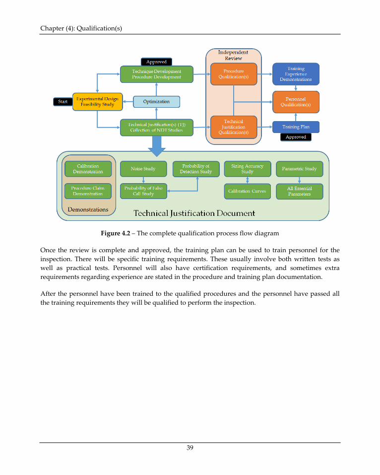
The procedure and technical justification are used to make a training plan. Once the procedure is approved, the technical justification and the training plan are complete, they will be sent to an independent review or qualification board. The specific method of approval from the independent organization will vary based on their internal policies and the level of qualification being sought. The level of the TJ is discussed with more detail in section 8.2.1.
The entire qualification process flow diagram is shown in Figure 4.2. The orange box surrounding the procedure and technical justification qualifications represents the independent review.
Chapter (4): Qualification(s)
39
Figure 4.2 – The complete qualification process flow diagram
Once the review is complete and approved, the training plan can be used to train personnel for the inspection. There will be specific training requirements. These usually involve both written tests as well as practical tests. Personnel will also have certification requirements, and sometimes extra requirements regarding experience are stated in the procedure and training plan documentation.
After the personnel have been trained to the qualified procedures and the personnel have passed all the training requirements they will be qualified to perform the inspection.
Chapter (24): Introduction to Design of Experiments (DoE)
223
CHAPTER (24): INTRODUCTION TO DESIGN OF EXPERIMENTS (DoE)
This chapter is a very brief introduction to the design of experiments (DoE or sometimes DOX).
The topic of experimental design is a very diverse subject, a large number of books have been written on the subject. The science of experimental design has been around for more than a century. In this time there has been great progress developing and understanding the design of experiments.
There is a fundamental rule in chemistry – “Garbage in equals garbage out.” This rule can be applied to so many areas in life. Experiments are not any different.
This is a very good rule for any experiment. If the experiment does not have good control samples the experimental analysis will have low value. To conduct a good experiment, good samples are required.
Importance of samples cannot be overstated.
Due to economic factors the number of samples is constantly reduced or minimized. This drives the need for efficiency. Efficiency during experimentation usually only comes from very well designed experiments.
This is where the science of experimental design becomes essential.
24.1 THE TERMINOLOGY Experiment: Experiments are controlled studies or procedures that measure states, test a hypothesis or help reveal facts that are not known. Some experiments are performed to verify facts that are known. These are demonstration type experiments. They can be used to generate supporting evidence or quantify repeatability of a system.
Test: Test refers to a process of assessing quality and/or reliability. It can also refer to assessing a condition or taking measurements from a sample. A test normally is a single measurement, while an experiment is a group of tests.
Treatment: Treatment is a type of parameter being tested. For a UT example, the %SH signal response is being recorded. The experiment is being tested by changing the probe frequency and pulse width. This would be an example experiment with 2 treatments.
Level: The level for an experiment refers to the number of different values applied to a test parameter or treatment. For a UT example, the %SH signal response is being recorded. The experiment is being
Chapter (24): Introduction to Design of Experiments (DoE)
224
tested with 2.5 MHz, 5.0 MHz, and 7.5 MHz. This would be an example experiment with 3 levels for the frequency treatment.
Factor: A factor is a parameter that has influence on a test or experiment result. All influential parameters are factors. Factors are either used as treatments or they are attempted to be controlled.
Block: A group of similar experimental units.
Control: Control refers to an experiment that is going to be compared to other experiments with changes in test parameters. This is a control experiment. A baseline inspection is a type of control experiment. Control in an experiment refers to isolating parameters to eliminate variation. There is also a type of control involving the knowledge of experimental conditions. For example, when testing an inspector’s capability to analyze data, the indications required to report are left unknown for the test. This is a type of blind test control.
Variable: Variable and parameter can mean the same thing. Both a parameter and a variable can change. In an experiment, the term variable means a parameter that the experiment has control over changing. Variables are parameters that are intentionally changed with control during an experiment.
Independent Variable: An independent variable is a variable whose variation does not depend upon another variable. The independent variable should be set up as the test variable. This is usually set up to represent the X axis.
Dependent Variable: A dependent variable will vary when other variable are changed. This is usually the variable that represents the Y axis. With most experiments there is a desire to find a relationship between the change in the independent variable (X) and the dependent variable (Y).
Hypothesis: A hypothesis is an idea, rule, or prediction that is assumed from limited evidence. It is an educated guess based on known theoretical knowledge and conditions of the test. It is designed as a starting point for further experimentation to gain supporting evidence or evidence that the hypothesis is incorrect.
1-FAAT: Acronym for an experiment where one factor is changed and all other factors are fixed during each run of the experiment or measurement.
Factorial: A factorial is a mathematical operation. With experimental design, a factorial is a set of experiments that is a combination of the factors and levels. Factorial experiments come from the words ‘factor combination or combinatorial’ experiment.

Chapter (24): Introduction to Design of Experiments (DoE)
225
24.2 DESIGN OF EXPERIMENTS (DOE)
24.2.1 WHAT IS EXPERIMENTAL DESIGN? Experimental design is the science of designing tasks that are intended to describe or explain variations in signal response (information) that is under test or controlled conditions. A hypothesis is an educated guess based on known theoretical knowledge and conditions of the test. It is designed as a starting point for further experimentation to gain supporting evidence or evidence that the hypothesis is incorrect.
Testing a hypothesis is one type of experiment. Testing to enable optimization is another type of testing.
The best way to explain this concept is with an example. This example will show that a factorial designed test is better than a one-factor-at-a-time test. This will be true for this example. Factorial testing is normally more powerful than one-factor-at-a-time test, but it is not always the best test.
24.2.2 EXPERIMENT DESIGN EXAMPLE A test is being performed where two parameters have been found to vary the voltage response in a probe. The system has 2 factors called A & B. A & B are treatments for the experiment.
Both factors can be set to different levels in the NDT system. Factor A can be set from 500kHz up to 5MHz and B can be set from 50ns up to 250ns measurement time.
The first set of tests were performed using 1.5MHz, since this was considered the most likely probe to yield the highest results. After the testing was complete, the results were graphed and the results can be seen in Figure 24.1. From this first one factor-at-a-time experiment, 1.5MHz had the highest voltage for 100ns. This could be the end of the testing with a conclusion that 1.5 volts is the highest possible voltage from the system. Most people would not be content without further testing. A second set of 1-FAAT experiments were conducted where every frequency was tested at 100ns. The results from this second test is shown in Figure 24.2.
Figure 24.1 – Frequency vs Voltage Figure 24.2 – Time vs Voltage
0
0.2
0.4
0.6
0.8
1
1.2
1.4
1.6
0 1 2 3 4 5 6
Volta
ge
Frequency (MHz)
Factor A vs Voltage
0
0.2
0.4
0.6
0.8
1
1.2
1.4
1.6
0 50 100 150 200 250 300
Volta
ge
Time (ns)
Factor B vs Voltage
Chapter (24): Introduction to Design of Experiments (DoE)
226
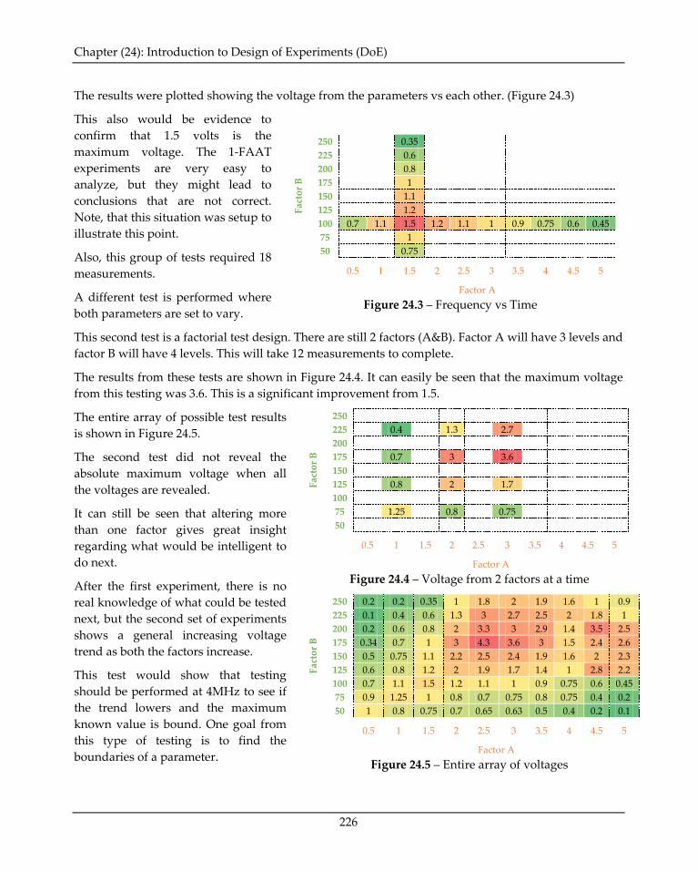
The results were plotted showing the voltage from the parameters vs each other. (Figure 24.3)
This also would be evidence to confirm that 1.5 volts is the maximum voltage. The 1-FAAT experiments are very easy to analyze, but they might lead to conclusions that are not correct. Note, that this situation was setup to illustrate this point.
Also, this group of tests required 18 measurements.
A different test is performed where both parameters are set to vary.
Fact
or B
250
0.35 225
0.6
200
0.8 175
1
150
1.1 125
1.2
100 0.7 1.1 1.5 1.2 1.1 1 0.9 0.75 0.6 0.45 75
1
50
0.75
0.5 1 1.5 2 2.5 3 3.5 4 4.5 5
Factor A
Figure 24.3 – Frequency vs Time
This second test is a factorial test design. There are still 2 factors (A&B). Factor A will have 3 levels and factor B will have 4 levels. This will take 12 measurements to complete.
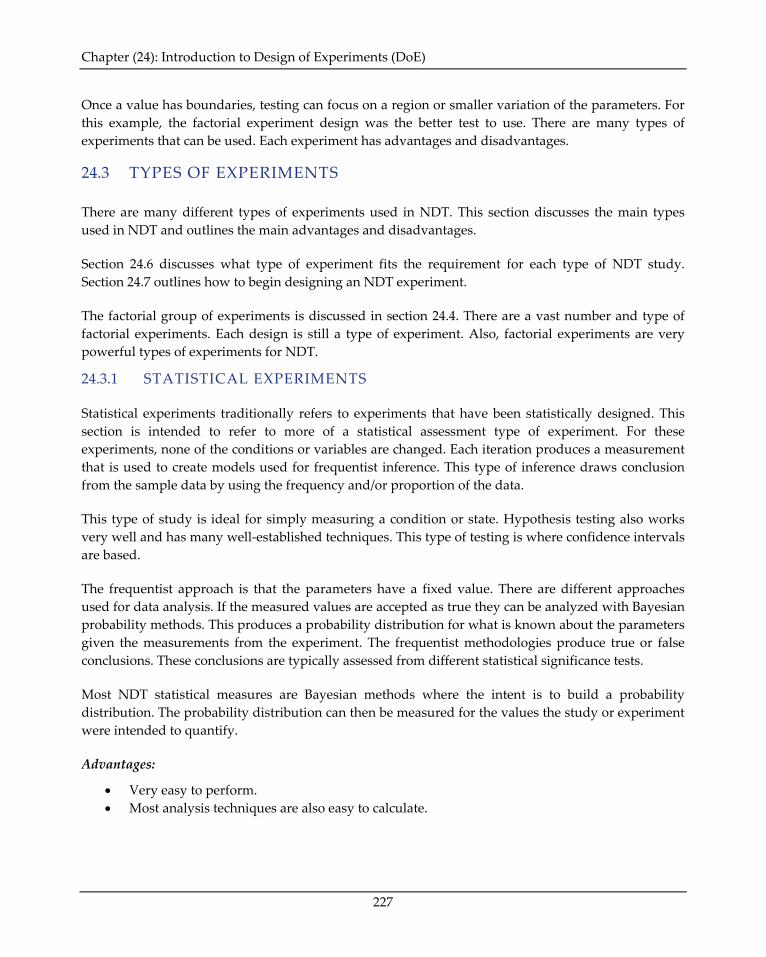
The results from these tests are shown in Figure 24.4. It can easily be seen that the maximum voltage from this testing was 3.6. This is a significant improvement from 1.5.
The entire array of possible test results is shown in Figure 24.5.
The second test did not reveal the absolute maximum voltage when all the voltages are revealed.
It can still be seen that altering more than one factor gives great insight regarding what would be intelligent to do next.
After the first experiment, there is no real knowledge of what could be tested next, but the second set of experiments shows a general increasing voltage trend as both the factors increase.
This test would show that testing should be performed at 4MHz to see if the trend lowers and the maximum known value is bound. One goal from this type of testing is to find the boundaries of a parameter.
Fact
or B
250 225
0.4
1.3
2.7 200
175
0.7
3
3.6 150
125
0.8
2
1.7 100
75
1.25
0.8
0.75 50
0.5 1 1.5 2 2.5 3 3.5 4 4.5 5
Factor A
Figure 24.4 – Voltage from 2 factors at a time
Fact
or B
250 0.2 0.2 0.35 1 1.8 2 1.9 1.6 1 0.9 225 0.1 0.4 0.6 1.3 3 2.7 2.5 2 1.8 1 200 0.2 0.6 0.8 2 3.3 3 2.9 1.4 3.5 2.5 175 0.34 0.7 1 3 4.3 3.6 3 1.5 2.4 2.6 150 0.5 0.75 1.1 2.2 2.5 2.4 1.9 1.6 2 2.3 125 0.6 0.8 1.2 2 1.9 1.7 1.4 1 2.8 2.2 100 0.7 1.1 1.5 1.2 1.1 1 0.9 0.75 0.6 0.45 75 0.9 1.25 1 0.8 0.7 0.75 0.8 0.75 0.4 0.2 50 1 0.8 0.75 0.7 0.65 0.63 0.5 0.4 0.2 0.1
0.5 1 1.5 2 2.5 3 3.5 4 4.5 5
Factor A
Figure 24.5 – Entire array of voltages
Chapter (24): Introduction to Design of Experiments (DoE)
227
Once a value has boundaries, testing can focus on a region or smaller variation of the parameters. For this example, the factorial experiment design was the better test to use. There are many types of experiments that can be used. Each experiment has advantages and disadvantages.
24.3 TYPES OF EXPERIMENTS
There are many different types of experiments used in NDT. This section discusses the main types used in NDT and outlines the main advantages and disadvantages.
Section 24.6 discusses what type of experiment fits the requirement for each type of NDT study. Section 24.7 outlines how to begin designing an NDT experiment.
The factorial group of experiments is discussed in section 24.4. There are a vast number and type of factorial experiments. Each design is still a type of experiment. Also, factorial experiments are very powerful types of experiments for NDT.
24.3.1 STATISTICAL EXPERIMENTS
Statistical experiments traditionally refers to experiments that have been statistically designed. This section is intended to refer to more of a statistical assessment type of experiment. For these experiments, none of the conditions or variables are changed. Each iteration produces a measurement that is used to create models used for frequentist inference. This type of inference draws conclusion from the sample data by using the frequency and/or proportion of the data.
This type of study is ideal for simply measuring a condition or state. Hypothesis testing also works very well and has many well-established techniques. This type of testing is where confidence intervals are based.
The frequentist approach is that the parameters have a fixed value. There are different approaches used for data analysis. If the measured values are accepted as true they can be analyzed with Bayesian probability methods. This produces a probability distribution for what is known about the parameters given the measurements from the experiment. The frequentist methodologies produce true or false conclusions. These conclusions are typically assessed from different statistical significance tests.
Most NDT statistical measures are Bayesian methods where the intent is to build a probability distribution. The probability distribution can then be measured for the values the study or experiment were intended to quantify.
Advantages:
• Very easy to perform. • Most analysis techniques are also easy to calculate.

Chapter (24): Introduction to Design of Experiments (DoE)
228
Disadvantages: • The required number of measures to ensure accuracy is high. • Time for data acquisition can be high. • Lower sample availability can cause errors when inferring one sample will match all samples
or other samples.
24.3.2 ONE FACTOR-AT-A-TIME (1-FAAT)
When first starting to perform experiments the one-factor-at-a-time method is the most commonly used method. The methodology is very simple to perform. One factor is varied, while all other parameters are strictly controlled. This type of experiment is the simplest experiment to perform.
For some situations the one-factor-at-a-time experiment is the best choice, but when multiple variables are involved in a relationship other experiments are usually a better option.
Advantages: • One of the simplest experiment designs. • Typically results can be gain quickly.
Disadvantages: • Complex relationships are not suited for this experiment. • It can lead to conclusions about optimization that are not correct.
24.3.3 QUASI-EXPERIMENTS
Quasi-experiments are very similar to traditional experiment designs, but they do not have the random element. With Quasi-experiments allow the researcher or person performing the experiment to control the assignment to the treatment condition.
These types of experiments are seldom used in NDT experiments, but there are situations when they can provide information that cannot be gained from traditionally designed experiments.
This type of experiment design can be used for trying to learn variable interactions.
24.3.4 FIELD EXPERIMENTS
A field experiment is when a test is done in a real inspection situation instead of a laboratory condition.
The data that can be acquired from this type of experiment is ideal.
Advantages: • Data acquisition represent real inspections • Actual test parameters are evaluated
Disadvantages: • Most testing is blind and blind testing is not ideal for initial research • Data acquired is typically only ‘field find’ data and cannot be used in a traditional PoD model
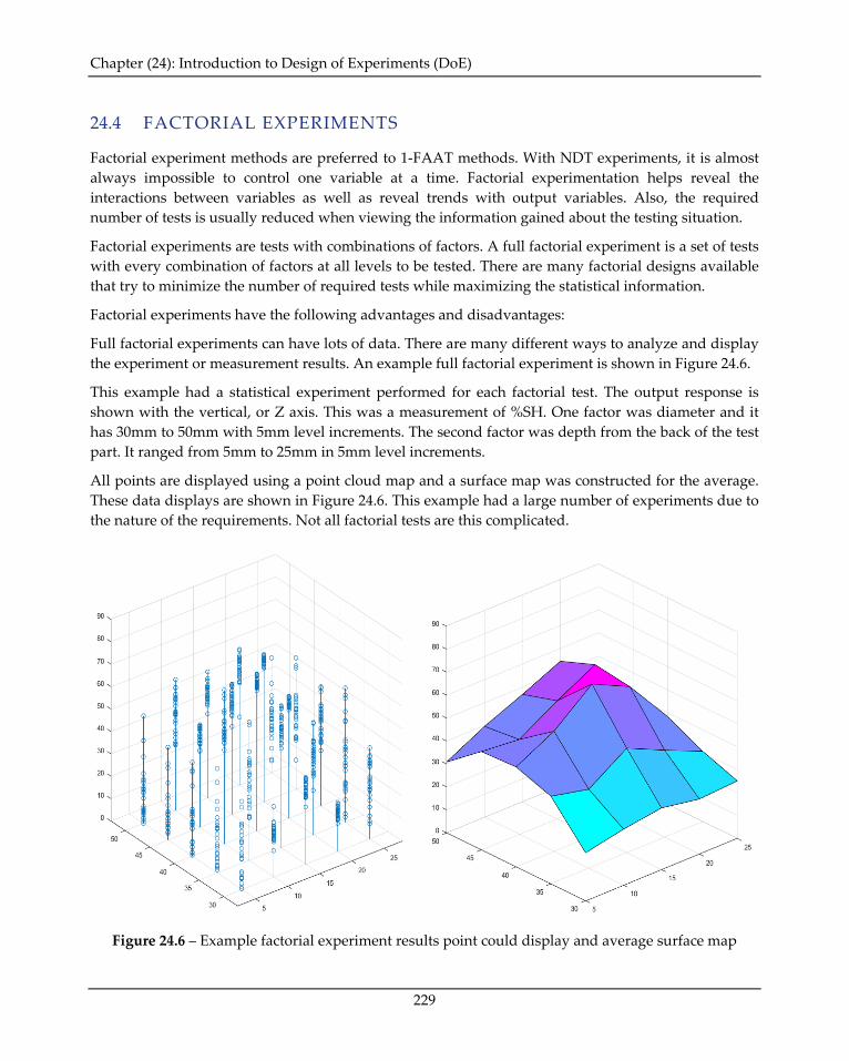
Chapter (24): Introduction to Design of Experiments (DoE)
229
24.4 FACTORIAL EXPERIMENTS
Factorial experiment methods are preferred to 1-FAAT methods. With NDT experiments, it is almost always impossible to control one variable at a time. Factorial experimentation helps reveal the interactions between variables as well as reveal trends with output variables. Also, the required number of tests is usually reduced when viewing the information gained about the testing situation.
Factorial experiments are tests with combinations of factors. A full factorial experiment is a set of tests with every combination of factors at all levels to be tested. There are many factorial designs available that try to minimize the number of required tests while maximizing the statistical information.
Factorial experiments have the following advantages and disadvantages:
Full factorial experiments can have lots of data. There are many different ways to analyze and display the experiment or measurement results. An example full factorial experiment is shown in Figure 24.6.
This example had a statistical experiment performed for each factorial test. The output response is shown with the vertical, or Z axis. This was a measurement of %SH. One factor was diameter and it has 30mm to 50mm with 5mm level increments. The second factor was depth from the back of the test part. It ranged from 5mm to 25mm in 5mm level increments.
All points are displayed using a point cloud map and a surface map was constructed for the average. These data displays are shown in Figure 24.6. This example had a large number of experiments due to the nature of the requirements. Not all factorial tests are this complicated.
Figure 24.6 – Example factorial experiment results point could display and average surface map
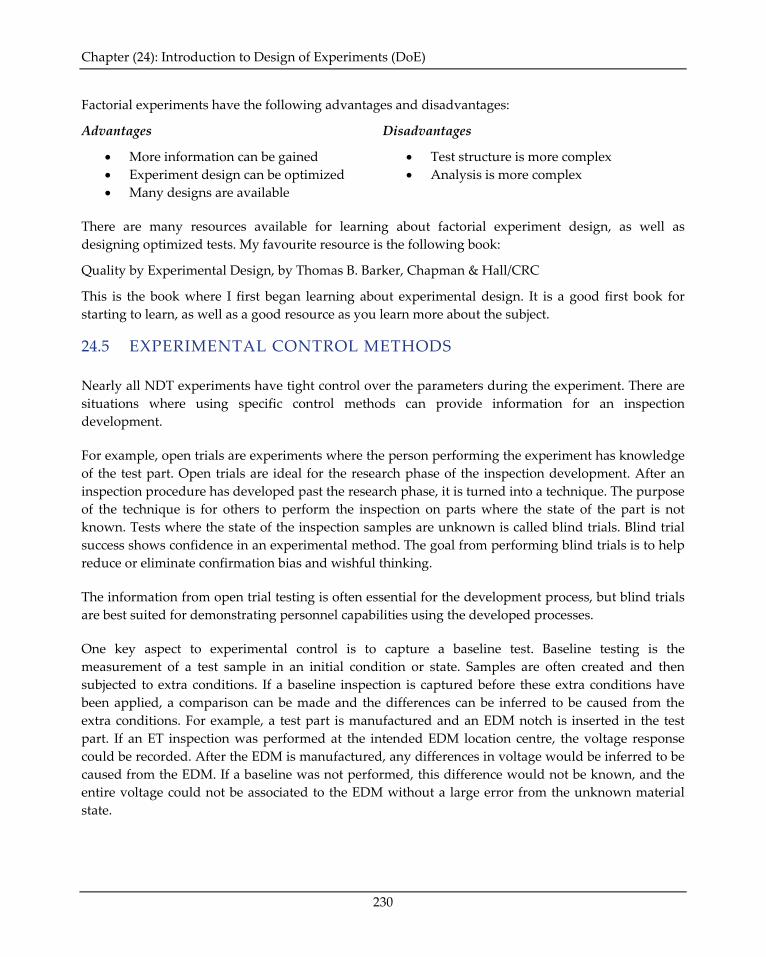
Chapter (24): Introduction to Design of Experiments (DoE)
230
Factorial experiments have the following advantages and disadvantages:
Advantages
• More information can be gained • Experiment design can be optimized • Many designs are available
Disadvantages
• Test structure is more complex • Analysis is more complex
There are many resources available for learning about factorial experiment design, as well as designing optimized tests. My favourite resource is the following book:
Quality by Experimental Design, by Thomas B. Barker, Chapman & Hall/CRC
This is the book where I first began learning about experimental design. It is a good first book for starting to learn, as well as a good resource as you learn more about the subject.
24.5 EXPERIMENTAL CONTROL METHODS
Nearly all NDT experiments have tight control over the parameters during the experiment. There are situations where using specific control methods can provide information for an inspection development.
For example, open trials are experiments where the person performing the experiment has knowledge of the test part. Open trials are ideal for the research phase of the inspection development. After an inspection procedure has developed past the research phase, it is turned into a technique. The purpose of the technique is for others to perform the inspection on parts where the state of the part is not known. Tests where the state of the inspection samples are unknown is called blind trials. Blind trial success shows confidence in an experimental method. The goal from performing blind trials is to help reduce or eliminate confirmation bias and wishful thinking.
The information from open trial testing is often essential for the development process, but blind trials are best suited for demonstrating personnel capabilities using the developed processes.
One key aspect to experimental control is to capture a baseline test. Baseline testing is the measurement of a test sample in an initial condition or state. Samples are often created and then subjected to extra conditions. If a baseline inspection is captured before these extra conditions have been applied, a comparison can be made and the differences can be inferred to be caused from the extra conditions. For example, a test part is manufactured and an EDM notch is inserted in the test part. If an ET inspection was performed at the intended EDM location centre, the voltage response could be recorded. After the EDM is manufactured, any differences in voltage would be inferred to be caused from the EDM. If a baseline was not performed, this difference would not be known, and the entire voltage could not be associated to the EDM without a large error from the unknown material state.
Chapter (24): Introduction to Design of Experiments (DoE)
231
Open and blind trials represent different states of an inspection development. The development starts in the research phase with open trials. Once the research phase is complete or near completion, the testing moves to blind trials. The analysis of the data also has the same progression. Data analysis personnel are shown or taught using open trials and they are tested or qualified using blind trials.
There is another analysis technique for higher level or critical analysis. This is the round-robin methodology. This involves a primary analysis and a secondary analysis. The primary analysis personnel are different than the secondary personnel. These two analysis groups do not discuss results. Each group performs the analysis of the data independently. A third group of analysis personnel review the results from primary and secondary analysis. This third group is usually referred to as the resolution analysis group. If primary and secondary analysis agree, the data is considered correct and complete. For values or records that have differences between primary and secondary analysis, the resolution analysis decides if the primary or secondary analyst are correct. The resolution analyst will typically have greater experience and can also decide that both primary and secondary analysis is incorrect. The round-robin analysis methodology is commonly used in the nuclear industry for nearly all analysis.
24.6 EXAMPLE STUDY DESIGNS
Different types of NDT studies were discussed in Chapter (9): Introduction to TJ Studies.
The following studies were discussed in this chapter:
• Signal Variance • Sizing Accuracy • Probability of Detection • Parametric Studies
• Noise Studies • Coverage Studies • Probability of False Call
Signal Variance:
Signal variance is best suited for a statistical experiment. Test situations are setup and repeated trials are performed. A model that represents the signal distribution is constructed.
Complex situations can arise where there are several parameters that can influence the variance. This can be performed with a sequential variation of a statistical experiment, or multiple variables can be evaluated with a factorial experiment design.
Noise Study: A noise study is best suited for a statistical experiment. There are several noise levels that can be evaluated, and one noise level usually never equals another. For example, in ECT testing the noise response from Vpp and Vmx are normally different. Also, the noise from 100kHz will not be the same as 200kHz. For a UT example, the noise at 50mm sound path will not be the same as 200mm. A 10MHz probe will not have the same noise as a 5MHz probe. Always ensure you are testing the right variables used in the procedure.
Chapter (24): Introduction to Design of Experiments (DoE)
232
Sizing Accuracy:
Sizing accuracy is a study that can be done using more than one type of experiment. The best method is based on the availability of samples. The more samples available the better the study.
When there are less samples, repeated or statistical experiments are better suited.
When more than one parameter influences the sizing accuracy, both should be evaluated using a factorial experiment.
The sizing accuracy can also be evaluated using one-factor-at-a-time methods or a sequential statistical combination with one-factor-at-a-time.
There are also model assisted methodologies available.
Coverage Study: A coverage study is a one-factor-at-a-time experiment. A very high level assessment could be a sequential statistical experiment, where one factor-at-a-time is statistically evaluated to measure the distribution of the signal at each coverage step used. This level of coverage analysis is rarely required, but it gives great detailed insight for an automated inspection system.
Probability of Detection:
This type of experiment or study is best suited using a factorial experiment design.
A one-factor-at-a-time methodology can be used to evaluate system capabilities regarding one factor.
There are also model assisted methods available.
Probability of False Call Study: This is more of an evaluation than a study or experiment. For the PoFC to be evaluated, both the PoD and a noise study are required. If either of these studies is not completed, they will be required to be completed before the evaluation can start.
Parametric Studies:
The parameters are the largest influence on the optimal experiment selection.
For studies where there is very little insight, a simple signal variation or statistical study can give intelligence towards the significance or levels of influence.
The nature of the parameter normally points to the optimal study. When multiple parameters are essential to the outcome of a dependent variable, a factorial experiment is likely the best option.
Chapter (24): Introduction to Design of Experiments (DoE)
233
To assess if a variable is a significant a one-factor-at-a-time approach can be used.
To evaluate if parameters can be isolated or what the resolution of a parameter is, a statistical experiment can be used.
24.7 DESIGNING AN EXPERIMENT
The process for designing a good experiment always starts with questions. The following questions are the most common general questions for beginning the process:
• What is the hypothesis & alternate hypothesis? • What are the essential parameters (test variables)? • What are the influential parameters (background variables)? • What are the other variables present? (They could be lurking or related in a way that is not
known.) • How many factors will the experiment be designed to have? • Are the factor levels fixed or random? • What are the required controls for the experiment? • What is the required sample size? • How many samples are required to achieve significance or accuracy for making a general
rule? • How are the experimental errors being handled or measured? • Is the act of measuring the experiment likely to alter the measurement itself?
In the first section of a good experiment template, all of these questions should be listed. When starting an experiment that is a higher level or one that has lots of unknowns or assumptions, it is usually best to start by addressing all of these questions in a written formal manner. Having this information really helps during the experimental design phase to focus the experiment towards the intended direction.
Also, it can be a great benefit to have the variables listed, if the experiment enters a deeper analysis phase or more experiments are required. Having an organized list of the essential and influential parameters can help reveal interactions or other unconsidered sources of variation.